

Page 1

OPERATOR’S MANUAL
MST 488-27
POWER MODULE CONTROLLER
INTERACTIVE DIGITALLY CONTROLLED
POWER MODULE SYSTEM
KEPCO INC.
An ISO 9001 Company.
POWER MODULE
MODEL
MST 488-27
CONTROLLER
ORDER NO. REV. NO.
IMPORTANT NOTES:
1) This manual is valid for the following Model and associated serial numbers:
MODEL SERIAL NO. REV. NO.
2) A Change Page may be included at the end of the manual. All applicable changes and
revision number changes are documented with reference to the equipment serial numbers. Before using this Instruction Manual, check your equipment serial number to identify
your model. If in doubt, contact your nearest Kepco Representative, or the Kepco Documentation Office in New York, (718) 461-7000, requesting the correct revision for your particular model and serial number.
3) The contents of this manual are protected by copyright. Reproduction of any part can be
made only with the specific written permission of Kepco, Inc.
Data subject to change without notice.
KEPCO®
©2000, KEPCO, INC
P/N 243-0880
KEPCO, INC. ! 131-38 SANFORD AVENUE ! FLUSHING, NY. 11352 U.S.A. ! TEL (718) 461-7000 ! FAX (718) 767-1102
email: hq@kepcopower.com
!
World Wide Web: http://www.kepcopower.com
THE POWER SUPPLIER™
Page 2

Page 3

INSTRUCTION MANUAL CORRECTION
KEPCO®
THE POWER SUPPLIER™
SECTION 3, OPERATION, add the following:
KEPCO MODEL MST 488-27
NOTE:
The VISA query function (included in the latest versions of the VISA libraries) is not supported
by the MST 488-27. In newer XP and Vista computers a delay is needed to insure the MST 48827 has time to return the response to the query. The VISA query has no provisions to add a
delay, nor can it issue a series of read strobes between sending the request and receiving data
from the device. Instead of the VISA query, use one of the two methods described below.
Method 2 is recommended.
1. Use a VISA Write followed by VISA Read with a small delay between the functions. The
delay is determined by computer speed. A 2 millisecond delay between the Write and Read
functions will be sufficient to insure that there is enough time to receive a response for all valid
queries.
2. Follow the VISA Write with a series of VISA Read strobes while waiting for the data available
bit to be true, followed by the VISA Read function when data is available. This method provides
the highest throughput.
MST488-27/080307
KEPCO, INC. ! 131-38 SANFORD AVENUE ! FLUSHING, NY. 11355 U.S.A. ! TEL (718) 461-7000 ! FAX (718) 767-1102
email: hq@kepcopower.com ! World Wide Web: http://www.kepcopower.com
Page 4

Page 5

Declaration of Conformity
Application of Council directives:
Standard to which Conformity is declared:
EN61010-1:2001 (Safety requirements for electrical equipment for measurement,
control and laboratory use - Part 1)
Manufacturer's Name and Address:
Importer's Name and Address:
Type of Equi pme nt:
Model No.:
73/23/EEC (LVD)
93/68/EEC (CE mark)
KEPCO INC.
131-38 SANFORD AVENUE
FLUSHING, N.Y. 11352 USA
P
O
C
E
V
I
T
A
T
N
E
S
E
R
P
E
R
Component Power Supply
[PRODUCT MODEL NUMBER]
Y
Year of Manufacture:
I, the undersigned, declare that the product specified above, when used in conjunction with the conditions of conformance set forth in the product instruction manual, complies with the requirements of the
Low Voltage Directive 73/23/EEC, which forms the basis for application of the CE Mark to this product.
Place: KEPCO Inc.
131-38 Sanford Ave.
Flushing, N.Y.11352 USA
Saul Kupferberg
(Full Name)
Date:
228-1348 DC-COMP/INST 052704
VP OF SALES
(position)
A
Page 6

Conditions of Conformance
Programming Module
When this product is used in applications governed by the requirements of the EEC, the following restrictions and conditions apply:
1. For European applications, requiring compliance to the Low Voltage Directive, 73/23/EEC, this power
supply is considered a component product, designed for “built in” applications. Because it is incomplete in construction, the end product enclosure must provide for compliance to any remaining electrical safety requirements and act as a fire enclosure. (EN61010-1:2001, Cl. 6, Cl. 7, Cl.8, and Cl. 9)
2. This power supply is designed for stationary installation either within an equipment rack or a KEPCO
Rack Adapter RA 55 or CA 400.
3. This power supply is considered a Class 1 (earthed) product. It is intended for use as part of equipment meant for test, measurement and laboratory use, and is designed to operate from single phase,
three wire power systems. This equipment must be installed in a specifically designed KEPCO rack
adapter and within a suitably wired equipment rack, utilizing a three wire (grounded) mains connection.
See wiring section of this manual for complete electrical wiring instructions. (EN61010-1:2001,
Cl.6.10.1)
4. This power supply has secondary output circuits that are considered SELV.
5. This power supply employs a supplementary circuit protector in the form of a fuse mounted within its
enclosure. The fuse protects the power supply itself from damage in the event of a fault condition. For
complete circuit protection of the end product, as well as the building wiring, it is required that a primary circuit protection device be fitted to the branch circuit wiring. (EN61010-1:2001 Cl. 9.5)
6. Hazardous voltages are present within this power supply during normal operation. All operator adjustments to the product are made via externally accessible switches, controls and signal lines as specified within the product operating instructions. There are no user or operator serviceable parts within
the product enclosure. Refer all servicing to qualified and trained Kepco service technicians.
B
228-1372 COND/CONFORM 052704
Page 7
SAFETY INSTRUCTIONS
1. Installation, Operation and Service Precautions
This product is designed for use in accordance with EN 61010-1 and UL 3101 for Installation Category 2,
Pollution Degree 2. Hazardous voltages are present within this product during normal operation. The
product should never be operated with the cover removed unless equivalent protection of the operator
from accidental contact with hazardous internal voltages is provided.
!
!
!
There are no operator serviceable parts or adjustments within the product enclosure.
Refer all servicing to trained service technician.
Source power must be removed from the product prior to performing any servicing.
This product is designed for use with nominal a-c mains voltages indicated on the
rating nameplate.
2. Grounding
This product is a Class 1 device which utilizes protective earthing to ensure operator safety.
The PROTECTIVE EARTHING CONDUCTOR TERMINAL must be properly con-
!
nected prior to application of source power to the product (see instructions on installation herein) in order to ensure safety from electric shock.
PROTECTIVE EARTHING CONDUCTOR TERMINAL - This symbol indicates the
point on the product to which the protective earthing conductor must be attached.
EARTH (GROUND) TERMINAL - This symbol is used to indicate a point which is
connected to the PROTECTIVE EARTHING TERMINAL. The component installer/
assembler must ensure that this point is connected to the PROTECTIVE EARTHING TERMINAL.
CHASSIS TERMINAL -This symbol indicates frame (chassis) connection, which is
supplied as a point of convenience for performance purposes (see instructions on
grounding herein). This is not to be confused with the protective earthing point, and
may not be used in place of it.
3. Electric Shock Hazards
This product outputs hazardous voltage and energy levels as a function of normal operation. Operators
must be trained in its use and exercise caution as well as common sense during use to prevent accidental
shock.
This symbol appears adjacent to any external terminals at which hazardous voltage
!
228-1369 SAFETY - (MST) 013004 C/(D Blank)
levels as high as 500V d-c may exist in the course of normal or single fault conditions.
This symbol appears adjacent to any external terminals at which hazardous voltage
levels in excess of 500V d-c may exist in the course of normal or single fault conditions.
Page 8

Page 9

TABLE OF CONTENTS
SECTION PAGE
SECTION 1 - INTRODUCTION
1.1 Scope of Manual ..................................................................................................................................... 1-1
1.2 General Description................................................................................................................................. 1-1
1.3 Specifications .......................................................................................................................................... 1-1
1.4 Equipment Supplied ................................................................................................................................ 1-4
1.5 Accessories ............................................................................................................................................. 1-4
SECTION 2 - INSTALLATION
2.1 Unpacking and Inspection ....................................................................................................................... 2-1
2.2 Installation ............................................................................................................................................... 2-1
2.2.1 Set (GPIB) Device Address, Configure RS 232................................................................................. 2-1
2.2.1.1 Using GPIB Only.......................................................................................................................... 2-1
2.2.1.2 Using RS 232 Only ...................................................................................................................... 2-2
2.2.1.3 Using both GPIB addressing and RS 232.................................................................................... 2-3
2.2.1.4 RS 232 Connections.................................................................................................................... 2-3
2.2.2 Start-up Language/Compatibility Mode/GPIB Addressing Default .................................................... 2-3
2.2.3 Set Shield Ground Jumper ................................................................................................................ 2-4
2.2.4 Final System Interconnections........................................................................................................... 2-4
2.3 Rear Terminations on the MST 488-27 ................................................................................................... 2-5
SECTION 3 - OPERATION
3.1 General.................................................................................................................................................... 3-1
3.2 IEEE 488 (GPIB) Bus Protocol................................................................................................................ 3-1
3.2.1 String Parsing.................................................................................................................................... 3-2
3.3 RS 232 Operation.................................................................................................................................... 3-3
3.3.1 RS 232 With GPIB addressing .......................................................................................................... 3-3
3.3.2 Serial INterface.................................................................................................................................. 3-3
3.3.3 RS 232 Implementation ..................................................................................................................... 3-4
3.3.3.1 Echo Mode................................................................................................................................... 3-5
3.3.3.2 Prompt Method ............................................................................................................................ 3-5
3.3.3.3 XON XOFF Method...................................................................................................................... 3-5
3.3.4 Programming Techniques to Optimize Power Supply performance.................................................. 3-6
3.4 SCPI Programming ................................................................................................................................. 3-6
3.4.1 SCPI Messages................................................................................................................................. 3-7
3.4.2 Common Commands/Queries ........................................................................................................... 3-7
3.4.3 SCPI Subsystem Command/Query Structure.................................................................................... 3-7
3.4.4 Program Message Structure.............................................................................................................. 3-8
3.4.4.1 Keyword....................................................................................................................................... 3-8
3.4.4.2 Keyword Separator ...................................................................................................................... 3-10
3.4.4.3 Query Indicator ............................................................................................................................ 3-10
3.4.4.4 Data ............................................................................................................................................. 3-10
3.4.4.5 Data Separator............................................................................................................................. 3-10
3.4.4.6 Message Unit Separator.............................................................................................................. 3-10
3.4.4.7 Root Specifier .............................................................................................................................. 3-10
3.4.5 Addressing Multiple Power Supplies ................................................................................................. 3-10
3.4.6 Understanding The Command Structure........................................................................................... 3-11
3.4.7 Program Message Syntax Summary................................................................................................. 3-12
3.4.8 Status Reporting................................................................................................................................ 3-12
3.4.8.1 Status Reporting Structure........................................................................................................... 3-12
3.4.8.2 Operational Status Register......................................................................................................... 3-13
3.4.8.3 QUEStionable Status Register..................................................................................................... 3-13
3.4.8.4 Multiple Logical Instruments ........................................................................................................ 3-14
3.4.9 SCPI Program Example..................................................................................................................... 3-16
3.5 CIIL Programming ................................................................................................................................... 3-16
MST488-27 SVC 013004
i
Page 10

TABLE OF CONTENTS
SECTION PAGE
APPENDIX A - IEEE 488.2 COMMAND/QUERY DEFINITIONS
A.1 Introduction............................................................................................................................................. A-1
A.2 *CLS — Clear Status Command .......................................................................................................... A-1
A.3 *ESE — Standard Event Status Enable Command................................................................................ A-1
A.4 *ESE? — Standard Event Status Enable Query..................................................................................... A-1
A.5 *ESR? — Event Status Register Query................................................................................................. A-2
A.6 *IDN? — Identification Query.................................................................................................................. A-2
A.7 *OPC — Operation Complete Command ............................................................................................... A-2
A.8 *OPC? — Operation Complete Query .................................................................................................... A-3
A.9 *OPT? — Options Query ........................................................................................................................ A-3
A.10 *RST — Reset Command....................................................................................................................... A-4
A.11 *SRE — Service Request Enable Command ........................................................................................ A-4
A.12 *SRE? — Service Request Enable Query .............................................................................................. A-4
A.13 *STB? — Status Byte Register Query ................................................................................................... A-4
A.14 *TRG — Trigger Command ................................................................................................................... A-4
A.15 *TST? — Self Test Query....................................................................................................................... A-5
A.16 *WAI — Wait-to-Continue Command ..................................................................................................... A-5
APPENDIX B - SCPI COMMAND/QUERY DEFINITIONS
B.1 Introduction............................................................................................................................................. B-1
B.2
B.3
B.4
B.5
B.6
B.7
B.8
B.9
B.10
B.11
B.12
B.13
B.14
B.15
B.16
B.17
B.18
B.19
B.20
B.21
B.22
B.23
B.24
B.25
B.26
B.27
B.28
B.29
B.30
B.31
B.32
B.33
B.34
B.35
INITiate[:IMMediate] Command .............................................................................................. B-1
INITiate:CONTinuous
Command................................................................................................. B-1
INITiate:CONTinuous Query ....................................................................................................... B-2
INSTrument:CATalog Query.......................................................................................................... B-2
INSTrument[:NSELect]
INSTrument[:SELect]
INSTrument[:SELect]?
INSTrument:STATe
MEASure[:SCALar]:CURRent[:DC]?
MEASure[:VOLTage][:SCALar][:DC]?
Command .............................................................................................. B-2
Command ................................................................................................ B-2
Query..................................................................................................... B-3
Command........................................................................................................ B-3
Query............................................................................. B-3
Query ........................................................................ B-4
OUTPut[:STATe] Command............................................................................................................. B-4
OUTPut[:STATe] Query ................................................................................................................... B-4
[SOURce:]CURRent[:LEVel][:IMMediate][:AMPlitude]
[SOURce:]CURRent[:LEVel][:IMMediate][:AMPlitude]
[SOURce:]CURRent:[:LEVel]TRIGgered[:AMPlitude]
[SOURce:]CURRent:[:LEVel]TRIGgered[:AMPlitude]?
[SOURce:]VOLTage[:LEVel][:IMMediate][:AMPlitude]
[SOURce:]VOLTage[:LEVel][:IMMediate][:AMPlitude]?
[SOURce:]VOLTage:[:LEVel]TRIGgered[:AMPlitude]
[SOURce:]VOLTage:[:LEVel]TRIGgered[:AMPlitude]?
[SOURce:]FUNCtion:MODE
STATus:OPERation:CONDition
STATus:OPEReration:ENABle
Command ......................................................................................... B-7
Query....................................................................................... B-7
Command .................................................................................. B-7
Command........................... B-4
Query.................................. B-4
Command .............................. B-5
Query .................................... B-5
Command........................... B-6
Query ............................... B-6
Command................................ B-6
Query .................................... B-6
STATus:OPEReration:ENABle? Query....................................................................................... B-7
STATus:OPERation[:EVENt]
STATus:PRESet
Command............................................................................................................... B-7
STATus:QUEStionable[:EVENt]?
STATus:QUEStionable:CONDition?
STATus:QUEStionable:ENABle
STATus:QUEStionable:ENABle?
STATus:QUEStionable:INSTrument[1]?
STATus:QUEStionable:INSTrument2?
STATus:QUEStionable:INSTrument[1]:ENABle
STATus:QUEStionable:INSTrument[1]:ENABle
Query ........................................................................................... B-7
Query.................................................................................. B-8
Query............................................................................. B-9
Command................................................................................ B-9
Query .................................................................................... B-9
Query ................................................................... B-9
Query ........................................................................ B-9
Command .............................................. B-10
Query..................................................... B-10
ii
MST488-27 SVC 013004
Page 11

TABLE OF CONTENTS
SECTION PAGE
B.36
B.37
B.38
B.39
B.40
B.41
B.42
B.43
B.44
B.45
B.46
B.47
B.48
B.49
STATus:QUEStionable:INSTrument2:ENABle
STATus:QUEStionable:INSTrument2:ENABle?
STATus:QUEStionable:INSTrument:ISUM
STATus:QUEStionable:INSTrument:ISUM:ENABle
STATus:QUEStionable:INSTrument:ISUM:ENABle?
SYSTem:COMMunication:GPIB:ADDRess
SYSTem:COMMunication:SERial:BAUD
SYSTem:COMMunication:SERial:ECHO
SYSTem:COMMunication:SERial:PACE
SYSTem:COMMunication:SERial:PROMpt
SYSTem:ERRor[:NEXT]?
SYSTem:LANGuage
SYSTem:SET
SYSTem:VERSion
Command .................................................................................................................... B-13
Query ................................................................................................................... B-13
Query..................................................................................................... B-11
Command.......................................................................................................... B-12
APPENDIX C - CIIL COMMAND DEFINITIONS
Command................................................... B-10
Query....................................................... B-10
Query................................................................. B-10
Command......................................... B-11
Query ............................................. B-11
Command ............................................................. B-11
Command................................................................ B-11
Command................................................................ B-11
Command................................................................ B-11
Command........................................................... B-11
MST488-27 SVC 013004
iii
Page 12

LIST OF FIGURES
FIGURE TITLE PAGE
1-1 MST488-27 Power Module Controller .......................................................................................................... vi
1-2 Remotely Controlled Power Supply Configurations Using Kepco Products............................................... 1-2
1-3 MST 488-27 Controller Outline Drawing .................................................................................................... 1-3
1-4 Controller to Power Module Interface (Typical).......................................................................................... 1-4
2-1 Configuration Controls................................................................................................................................ 2-5
2-2 Front and Rear Panels of MST 488-27 Power Module Controller.............................................................. 2-6
3-1 RS 232 Implementation.............................................................................................................................. 3-4
3-2 Tree Diagram of SCPI Commands Used with MST 488-27 Controller ...................................................... 3-7
3-3 Message Structure ..................................................................................................................................... 3-9
3-4 Status Reporting Structure ......................................................................................................................... 3-14
3-5 Expansion of QUEStionable Register for Multiple Logical Instruments...................................................... 3-15
3-6 Typical Example Of MST 488-27 Controller Program Using SCPI Commands ......................................... 3-16
A-1 GPIB Commands ....................................................................................................................................... A-3
A-2 Using the *WAIt-to-continue Command ..................................................................................................... A-5
B-1 Use of INSTrument:CATalog Query.......................................................................................................... B-2
B-2 Identifying and Selecting Devices on BITBUS ........................................................................................... B-3
B-3 Programming the Output............................................................................................................................ B-5
B-4 Programming Current................................................................................................................................. B-6
B-5 Using Status Commands and Queries ....................................................................................................... B-8
C-1 FNC — Function Command....................................................................................................................... C-1
C-2 INX — Initiate Op Code Command ............................................................................................................ C-2
C-3 FTH — Fetch Command ............................................................................................................................ C-2
C-4 SET Command........................................................................................................................................... C-3
C-5 OPN, CLS — Open, Close Relay Commands ........................................................................................... C-4
C-6 RST — Reset Command............................................................................................................................ C-4
C-7 CNF, IST — Confidence Test, Internal Self Test Commands.................................................................... C-4
C-8 STA — Status Command ........................................................................................................................... C-5
C-9 GAL — Go to Alternate Language Command........................................................................................... C-6
iv
MST488-27 SVC 013004
Page 13

LIST OF TABLES
TABLE TITLE PAGE
1-1 General Specifications for MST 488-27 Controller ......................................................................................1-1
1-2 Accessories .................................................................................................................................................1-4
2-1 Device Address Selection ...........................................................................................................................2-2
2-2 Start-up Language/Compatibility Mode/GPIB Addressing Selection ..........................................................2-4
2-3 Compatibility Mode Differences ..................................................................................................................2-4
2-4 Input/Output Pin Assignments ....................................................................................................................2-7
3-1 IEEE 488 (GPIB) Bus Interface Functions ..................................................................................................3-1
3-2 IEEE 488 (GPIB) Bus Command Mode Messages .....................................................................................3-2
3-3 IEEE 488 (GPIB) Bus Data Mode Messages ..............................................................................................3-2
3-4 SCPI Command Index ................................................................................................................................3-8
3-5 Rules Governing Shortform Keywords ........................................................................................................3-9
A-1 IEEE 488.2 Command/query Index ........................................................................................................... A-1
A-2 Standard Event Status Enable Register and Standard Event Status Register Bits ................................... A-1
A-3 Service Request Enable and Status Byte Register Bits ............................................................................. A-4
B-1 SCPI Subsystem Command/query Index .................................................................................................. B-1
B-2 Operation Condition Register, Operation Enable Register,
and Operation Event Register Bits .......................................................................................................... B-7
B-3 Questionable Event Register, Questionable Condition Register
and Questionable Condition Enable Register Bits .................................................................................. B-8
B-4 Questionable Instrument Register 1 Bits ...................................................................................................B-9
B-5 Questionable Instrument Register 1 Bits ...................................................................................................B-10
B-6 Error Messages ..........................................................................................................................................B-12
C-1 CIIL Subsystem Command/query Index ....................................................................................................C-1
C-2 CIIL Error Messages ..................................................................................................................................C-5
C-3 CIIL Error Handling Utility Commands .......................................................................................................C-6
MST488-27 SVC 013004
v
Page 14
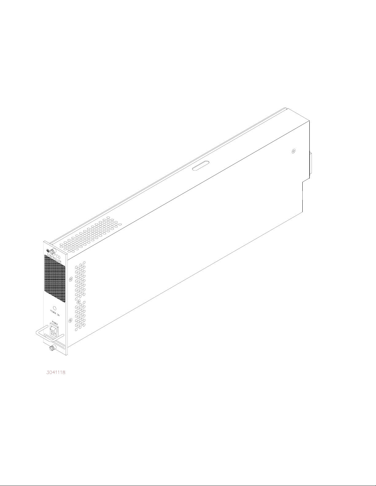
FIGURE 1-1. MST488-27 POWER MODULE CONTROLLER
vi
MST488-27 SVC 013004
Page 15

FIGURE 0-1.
SECTION 1 - INTRODUCTION
1.1 SCOPE OF MANUAL
This manual contains the specifications and instructions for the installation and operation of the
Model MST 488-27 Power Module Controller (Figure 1-1), manufactured by Kepco, Inc., Flushing, N.Y. U.S.A.. Parts lists and schematic diagrams are included in Section 4.
1.2 GENERAL DESCRIPTION
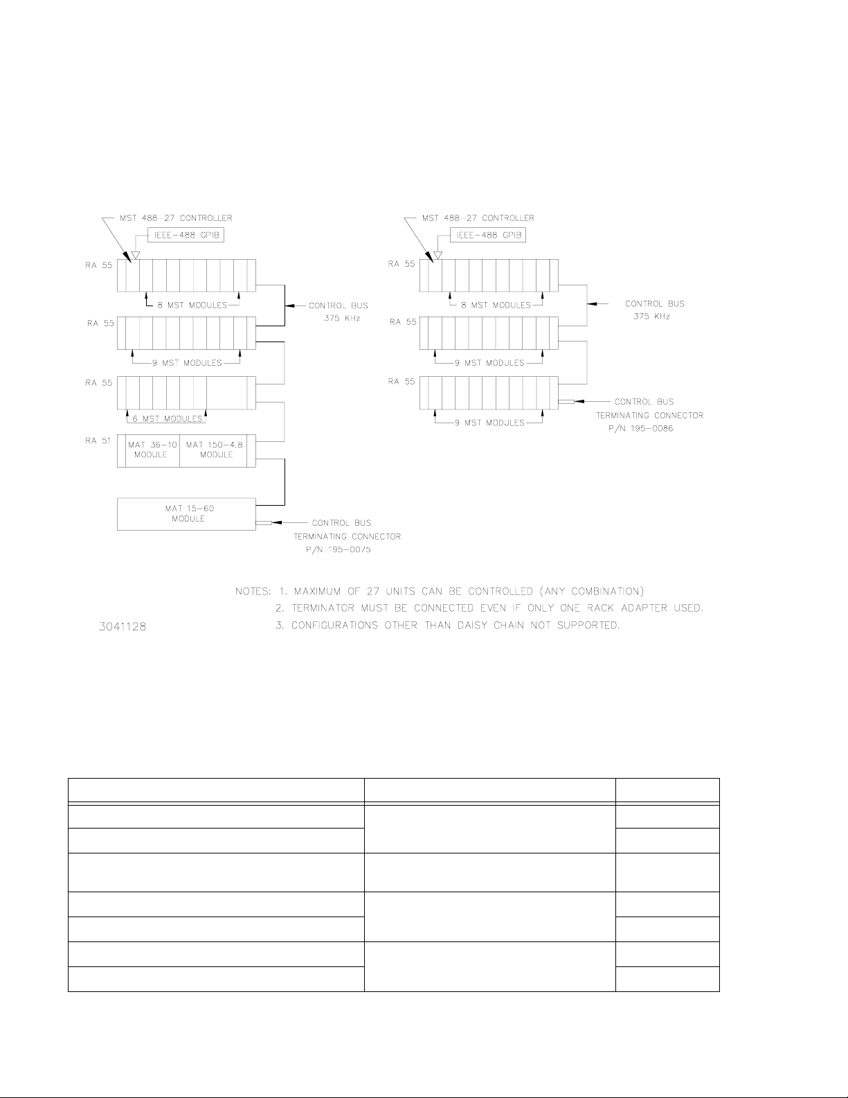
The Kepco model MST 488-27 is a Power Module Controller which has the capability to program, control and monitor the outputs of up to 27 Kepco MAT, MBT, MST or BOP power supplies (power modules). The MST 488-27 communicates with its Host computer over the IEEE
488 bus (GPIB) using either CIIL (Control Interface Intermediate Language) or SCPI (Standard
Commands for Programmable Instruments) Languages. An auxiliary input port allows for communication via the RS 232-C (EIA 232) standard serial communications bus. The MST 488-27
communicates with the MAT, MBT, MST or BOP series using the IEEE1118 two-wire serial bus,
hereafter referred to as the Control Bus, which allows control over distances up to a maximum
of 1000 feet (300 meters) (see Figure 1-2).
The IEEE 488 GPIB interface functions implemented by the controller are defined by the IEEE
488 Standard, and described in Table 3-1.
The MST 488-27 Controller interfaces to an MST power module via either the RA 55 or CA 400
Rack Adapter; interconnection to the Host Computer on the GPIB is made via an IEEE 488
standard cable. If the serial port is used for communications between the controller and a computer terminal, a 9 pin null-modem RS 232-C connector/cable is required.
The MST 488-27 Controller is comprised of a single-board computer (SBC) and power supply
housed in a 1/9 Rack (7” high by 1-3/4” wide by 20-1/4” deep) case (see Figure 1-3).
1.3 SPECIFICATIONS (REFER TO FIGURE 1-3 AND TABLE 1-1)
The Host Computer can set the output voltage with current limit, or the output current with voltage limit. The Host Computer can then have the MST 488-27 read back the actual output voltage and current delivered by each of the MST power modules to their respective loads. The
MST 488-27 is continually polling all of the power modules on the Control Bus for flags of catastrophic and noncatastrophic errors. All data transmissions over the GPIB are ASCII encoded.
The values for the command parameters can be written in integer, decimal or scientific notation.
The responses from the MST 488-27 are detailed in Section 3 of this manual.
TABLE 1-1. GENERAL SPECIFICATIONS FOR MST 488-27 CONTROLLER
FEATURE SPECIFICATION
A-C Input Requirements
Ambient Operating Temperature Range 0 to +55 ° C
Storage Temperature Range –20 to +75° C
Dimensions 7” H x 1-3/4” W x 20-1/4” D
Color (front panel) Kepco gray, Hartin Paint No. 15-22493
Mounting Rack Adapter (Kepco RA 55 or CA 400)
95 to 264V a-c, 47 to 63 Hz, approximately 12
Watts maximum
MST488-27 SVC 013004
1-1
Page 16

1-2
FIGURE 1-2. REMOTELY CONTROLLED POWER SUPPLY CONFIGURATIONS USING KEPCO PRODUCTS
800
MST488-27 SVC 013004
Page 17
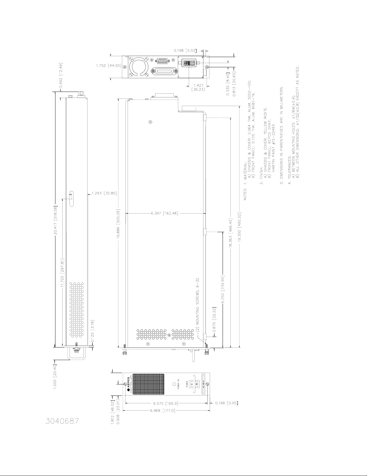
FIGURE 1-3. MST 488-27 CONTROLLER OUTLINE DRAWING
MST488-27 SVC 013004
1-3
Page 18
1.4 EQUIPMENT SUPPLIED
A terminator, Kepco P/N 195-0086, is included with each controller to provide proper termination
of the IEEE 1118 control bus. In configurations where power modules are daisy chained on the
IEEE 1118 control bus (see Figure 1-4), the last power module control bus outlet (in the daisy
chain) must be terminated with the IEEE Control Bus Terminator supplied with the controller to
reduce spurious noise and provide proper impedance matching.
FIGURE 1-4. CONTROLLER TO POWER MODULE INTERFACE (TYPICAL)
1.5 ACCESSORIES
Accessories for the MST 488-27 are listed in Table 1-2.
TABLE 1-2. ACCESSORIES
ITEM FUNCTION
Terminator - 5-pin connector Termination for daisy chain on IEEE 1118 bus. 195-0075
Terminator - 9-pin connector 195-0086
Cable - two 5-pin connectors Daisy chain Kepco Power Supplies with 5-pin
connectors on IEEE 1118 bus.
Cable - one 5-pin and one 9-pin connector, ~6 ft. (2 m) Daisy chain MST 488-27and Kepco Power Sup-
plies with 5-pin connector on IEEE 1118 bus.
Cable - one 5-pin and one 9-pin connector, ~12 ft. (4 m) 118-0852
Cable - two 9-pin connectors, ~ 6 ft. (2 m) Daisy chain MST 488-27and Kepco Power Sup-
plies with 9-pin connector on IEEE 1118 bus.
Cable - two 9-pin connectors, ~ 12 ft. (4 m) 118-0853
1-4
PART NUMBER
118-0699
118-0749
118-0844
MST488-27 SVC 013004
Page 19

SECTION 2 - INSTALLATION
2.1 UNPACKING AND INSPECTION
The Model MST 488-27 has been carefully inspected and tested prior to packing. Inspect the
shipping carton upon receipt for evidence of damage during transit. Save the original packing
material. If any indication of damage is found, file a claim immediately with the responsible
transport service.
For repairs of a product damaged in shipment, contact the Kepco Factory Representative nearest you or the Kepco Sales Department directly for further instruction.
2.2 INSTALLATION
The installation and set-up procedure for the MST 488-27 consists of the following steps:
1. Set Device Address and/or configure RS 232 port (PAR. 2.2.1).
2. Select start-up language (SCPI or CIIL), GPIB addressing (Primary/Secondary) and Compatibility Mode (PAR. 2.2.2).
3. Set Shield Ground Jumper (PAR. 2.2.3).
4. Perform final system inteconnections (PAR. 2.2.4).
2.2.1 SET (GPIB) DEVICE ADDRESS, CONFIGURE RS 232 (SEE FIGURE 2-1)
A single set of DIP switches, accessible through an access hole on the top (see Figure 2-1), are
used both to set the GPIB Device Address (the factory default is 6) and to configure the RS 232
port. The following paragraphs explain how to proceed if using GPIB only (PAR. 2.2.1.1), RS
232 only (PAR. 2.2.1.2) or both (PAR. 2.2.1.3). RS 232 connections are explained in PAR.
2.2.1.4) and RS 232 operation is described in PAR. 3.3.
NOTE: When a jumper is present between CTS and RTS at the MST 488-27, the DIP switches
configure the RS 232 port as well as set the GPIB address. If the default RS 232 configuration will be used, be sure the RS 232 cable has no internal connections between
CTS and RTS.
2.2.1.1 USING GPIB ONLY
The Device Address is the permanent Listener and Talker address of the MST 488-27 on the
GPIB. It is factory preset to address 6. If a different Device Address is required in your system,
proceed as follows. There are 31 (0-30) possible choices (See Table 2-1).
1. Place MST 488-27 power module controller with the top of the unit facing you, front panel to
the right.
2. The Device Address DIP switches are positions 1 through 5 (from right to left, see Figure
2-1). These switches are preset by Kepco to address 6. For other device addresses set
them according to Table 2-1.
MST 488-27 013004
2-1
Page 20

TABLE 2-1. DEVICE ADDRESS SELECTION
DECIMAL
ADDRESS
000000
100001
200010
300011
400100
500101
600110
700111
801000
901001
1001010
1101011
1201100
1301101
1401110
1501111
1610000
1710001
1810010
1910011
2010100
2110101
2210110
2310111
2411000
2511001
2611010
2711011
2811100
2911101
3011110
A5 A4 A3 A2 A1
SELECTOR SWITCH SECTION
(SIGNAL LINE)
2.2.1.2 USING RS 232 ONLY
If the default configuration (9600 baud, Echo = on, XON = off) is acceptable, leave DIP switch
positions 1-5 as is. To change from the default configuration, install an external jumper between
RTS and CTS on the RS 232 cable at the MST 488-27. The RS 232 Port can now be configured
using the DIP switches. Place MST 488-27 power module controller with the top of the unit facing you, front panel to the right. The Device Address DIP switches are positions 1 through 5
(from right to left, see Figure 2-1).
• Baud Rate: Sw Pos 4/5 (00 = 9600, 11 = 19200, 10 = 4800, 01 = 2400)
• Echo: Sw Pos 3 (1 = enable, 0 = disable)
• XON: Sw Pos 2 (1 = disable, 0 = enable)
2-2
MST 488-27 013004
Page 21

2.2.1.3 USING BOTH GPIB ADDRESSING AND RS 232
The same switches are used to configure the RS 232 port and establish the GPIB address; proceed as follows to use both.
1. First, configure the RS 232 port. The default cnfiguration (9600 baud, Echo = on, XON = off)
corresponds to a GPIB address of 6. If this is acceptable, no further configuration is necessary. Proceed to step 2 to change the RS 232 configuration. If the RS 232 configuration is
OK but the GPIB address needs to be changed, proceed to step 3.
2. For an RS 232 configuration other than the default, refer to PAR. 2.2.1.2. If the GPIB address
that corresponds to the RS 232 configuration needs to be changed, proceed to step 3.
3. To change the GPIB address without changing the RS 232 configuration, use the RS 232
port to send the "syst:comm:gpib:addr n" command (where n = the desired GPIB address).
This allows the DIP switches to determine the RS 232 configuration while the software command establishes the GPIB address.
2.2.1.4 RS 232 CONNECTIONS
Since the MST 488-27 uses a 9-pin male connector, it is classified as a Data Terminal Equipment (DTE) in accordance with the RS 232 Standard (equipment using a female connector is
classified as Data Communication Equipment, DCE).
Either a DTE-to-DTE or a null modem cable is required to connect the MST 488-27 to an IBMPC compatible computer. This cable has only three wires and connects RXD at one end to TXD
at the other end. The RS232-C port control lines (Table 2-4) are used to activate special feature
by means of jumpers at the MST 488-27; refer to Table 2-2 and PAR. 2.2.1 for details. Refer to
PAR. 3.3 for RS 232 operation. NOTE: Be sure the cable used has no unintended internal connections, particularly between RTS and CTS.
2.2.2 START-UP LANGUAGE/COMPATIBILITY MODE/GPIB ADDRESSING DEFAULT (SEE FIGURE 2-1)
Program Mode Bits P1 (DIP switch position A6, see Figure 2-1) and P2 (position A7) control the
start-up command language, secondary GPIB addressing with SCPI, and Compatibility Mode
as defined in Table 2-2.
Language - Selection is provided to choose either SCPI or CIIL command language. If SCPI is
selected, you can also choose to implement either primary or secondary GPIB addressing.
Compatibilty Mode - Certain features of the MST 488-27 can be configured to be fully 488.2/
SCPI compatible (Mode 0) or to be backward compatible with previous Kepco products (Mode
1). Differences between Mode 0 and Mode 1 functionality are explained in Table 2-3.
MST 488-27 013004
2-3
Page 22

TABLE 2-2. START-UP LANGUAGE/COMPATIBILITY MODE/GPIB ADDRESSING SELECTION
P1 P2 LANGUAGE
0* 0* SCPI MODE 1 Primary
0 1 CIIL Not Applicable Not Applicable
1 0 SCPI MODE 1 Secondary
1 1 SCPI MODE 0 Primary**
* Factory Default Configuration = P1 and P2 set to 0.
** In this mode, secondary addressing may be enabled by putting a jumper between DSR and RTS
of the RS 232 port (pins 6 and 7).
COMPATIBILTY MODE
(See Table 2-3)
GPIB ADDRESSING
TABLE 2-3. COMPATIBILITY MODE DIFFERENCES
FUNCTION
Device Clear
Status Uses Status Instrument Registers. Does not use Status Instrument Registers.
PON enable All status register enables are set to 0. All status register enables are set to 32767.
SYST:VERS? Returns 1997.0. Returns blank string.
(fully 488.2/SCPI compatible)
Clears internal registers but leaves
output voltage and current unchanged.
MODE 0
(backward compatible with previous Kepco products)
Clears internal registers, sets output voltage and current
to zero, sets output to OFF, and, if unit incorporates
relays, opens relays.
MODE 1
2.2.3 SET SHIELD GROUND JUMPER (SEE FIGURE 2-1)
The jumper sets the Shield Ground state for the AC/control bus connector and is accessible
after the cover is removed:
• JUMPER INSTALLED = shield grounded (factory default)
• JUMPER REMOVED = shield not grounded
2.2.4 FINAL SYSTEM INTERCONNECTIONS
1. Install the MST 488-27 in the left-most slot of the RA 55 or CA 400 Rack Adapter in accordance with instructions contained in the Rack Adapter manual (a connector must be
removed to accomodate the MST 488-27 controller.
2. Install all power modules in the Rack Adapter.
3. Connect the MST 488-27 to the GPIB and/or RS 232-C bus.
4. All power module outputs should be connected to their respective loads. For MST Power
Module Calibration see the MST Operator's Manual.
5. Connect input power to the Rack Adapter in accordance with the Rack Adapter manual.
2-4
MST 488-27 013004
Page 23

FIGURE 2-1. CONFIGURATION CONTROLS
2.3 REAR TERMINATIONS ON THE MST 488-27 (SEE FIGURE 2-2)
a. AC INPUT. The MST 488-27 draws power from the same source used to power the MST
power modules. Power is applied through the Rack Adapter via the AC/control bus connector.
b. IEEE 488 BUS. This port is a 24 pin IEEE 488 connector and conforms mechanically and
electrically to the IEEE 488 standard. Refer to Table 2-4 for pin assignments.
c. RS 232-C PORT. This port is a standard 9 pin RS 232-C (male) connector). Refer to Table
2-4 for pin assignments and PAR. 2.2.1.4 for additional information.
MST 488-27 013004
2-5
Page 24

FIGURE 2-2. FRONT AND REAR PANELS OF MST 488-27 POWER MODULE CONTROLLER
2-6
MST 488-27 013004
Page 25

TABLE 2-4. INPUT/OUTPUT PIN ASSIGNMENTS
CONNECTOR PIN SIGNAL NAME FUNCTION
1 SGND Signal Ground
2 RXD Receive Data
3 TXD Transmit Data
4 DTR (not used)
5 SGND Signal Ground
6 DSR See Note 2.
RS232-C
PORT
IEEE 488
PORT
7 RTS See Notes 1 and 2.
8 CTS See Note 1.
9 SGND Signal Ground
NOTE 1 Jumper installed between CTS and RTS allows DIP switches to configure RS 232
NOTE 2 Jumper installed beteen DSR and RTS allows secondary GPIB addressing if SCPII
1
2
3
4
5 EOI End or Identify
6 DAV Data Valid
7 NRFD Not Ready for Data
8 NDAC Not Data Accepted
9 IFC Interface Clear
10 SRQ Service Request
11 ATN Attention
12 SHIELD Shield
13
14
15
16
17 REN Remote Enable
18 GND Ground (signal common)
19 GND Ground (signal common)
20 GND Ground (signal common)
21 GND Ground (signal common)
22 GND Ground (signal common)
23 GND Ground (signal common)
24 LOGIC GND Logic Ground
port. Jumper NOT installed established default RS 232 configuration (9600 baud,
Echo on, XON off).
mode 0 (see Table 2-2) is selected
I
01
D
I
D
02
I
D
03
I
04
D
D
I
05
I
D
06
I
D
07
I
D
08
I/O Line
I/O Line
I/O Line
I/O Line
I/O Line
I/O Line
I/O Line
I/O Line
MST 488-27 013004
2-7/(2-8 Blank)
Page 26

Page 27

SECTION 3 - OPERATION
3.1 GENERAL
Kepco MST 488-27 Power Module Controller is programmed over a control bus using either
SCPI (Standard Commands for Programmable Instruments) or CIIL (Control Interface Intermediate Language) commands. SCPI and CIIL provide a common language used in an automatic
test system.
The control bus can be either the IEEE 488 standard communication bus (General Purpose
Interface Bus, GPIB), or the RS 232C communication bus. (Refer to Table 2-4 for input/output
signal allocations.) Connection of both GPIB and RS 232 ports simultaneously is not recommended.
NOTE: Upon power loss, all programmed values/configurations are lost and must be repro-
grammed.
3.2 IEEE 488 (GPIB) BUS PROTOCOL
Table 3-1 defines the interface capabilities of the MST 488-27 controller (Talker/Listener) relative to the IEEE 488 (GPIB) bus (reference document ANSI/IEEE Std 488: IEEE Standard Digital
Interface for Programmable Instrumentation) communicating with a Host Computer–Controller
(Talker/Listener).
TABLE 3-1. IEEE 488 (GPIB) BUS INTERFACE FUNCTIONS
FUNCTION
Source Handshake SH1 Complete Capability (Interface can receive multiline messages)
Acceptor Handshake AH1 Complete Capability (Interface can receive multiline messages)
Ta lk e r T 6
Listener L4 Basic listener, unaddress if MTA (My Talk Address) (one-byte address).
Service Request SR1
Remote/Local RL2 No Local lock-out.
Parallel Poll PP0 No Capability
Device Clear DC1
Device Trigger DT1 GET supported.
Controller C0 No Capability
SUBSET
SYMBOL
COMMENTS
Basic talker, serial poll, unaddress if MLA (My Listen Address) (one-byte
address)
Complete Capability. The interface sets the SRQ line true if there is an
enabled service request condition.
Complete Capability. DCL (Device Clear) and SDC (Selected Device Clear)
supported.
Tables 3-2 and 3-3 define the messages sent to the MST 488-27, or received by the MST 48827, via the IEEE 488 bus in IEEE 488 command mode and IEEE 488 data mode, respectively.
These messages are enabled during the “handshake” cycle, with the MST 488-27 controller
operating as either a Talker or a Listener.
MST488-27 013004
3-1
Page 28

3.2.1 STRING PARSING
When the MST 488-27 is in listen mode, strings are accepted. When the host controller sends
the last byte it can assert the EOI line to indicate the string is complete. The GPIB listener function automatically adds a LF to terminate the string input. The parsing software then processes
the string and if there are valid commands, the power supply is updated with the new control
input. Some GPIB host controllers do not have the ability to assert the EOI control line, however
the GPIB listener function will also terminate the string input when either a carriage return (0d
or Line Feed (0A
H
TABLE 3-2. IEEE 488 (GPIB) BUS COMMAND MODE MESSAGES
MNEMONIC MESSAGE DESCRIPTION COMMENTS
ATN Attention Received
DAC Data accepted Received or Sent
DAV Data Valid Received or Sent
DCL Device Clear Received
IFC Interface Clear Received
MLA My Listen Address Received
) character is received.
)
H
MTA My Talk Address Received
OTA Other Talk Address Received
RFD Ready for Data Received or Sent
SDC Selected Device Clear Received
SPD Serial Poll Disable Received
SPE Serial Poll Enable Received
SRQ Service Request Sent
UNL Unlisten Received
UNT Untalk Received
TABLE 3-3. IEEE 488 (GPIB) BUS DATA MODE MESSAGES
MNEMONIC MESSAGE DESCRIPTION COMMENTS
DAB
END
EOS
RQS
Data Byte Received or Sent
End Received or Sent
End of String Received or Sent
Request Service Sent
3-2
STB
Status Byte Sent
MST488-27 013004
Page 29

3.3 RS 232 OPERATION
The MST 488-27 controller may be operated via an RS 232-C terminal, or from a PC using a terminal emulation program. The default settings are as follows:
• Baud rate: 9600 (no jumper between RTS and CTS on RS 232 port)
• Parity: None
•Data Bits8
• Stop Bits 1
•Echo ON
• XON OFF
When a jumper on the RS 232 port (RTS, CTS) is present, the GPIB address switch settings
determine XON, echo, and baud rate as follows:
• Bit 5, 4 - baud rate (00 = 9600,11 = 19200, 10 = 4800, 01 = 2400)
• Bit 3 - Echo (1 = enable; 0 = disable)
• Bit 2 - XON (1 = disable; 0 = enable)
• Bit 1 - Not used for RS 232 configuration; only affects GPIB Address (see PAR.3.3.1).
NOTE: The RTS to CTS jumper must be installed externally, on the cable.
Upon power-up, the RS 232 port provides the following message (typical):
KEPCO POWER SUPPLY CONTROLLER V.4.6;PSC=6;PROGMODE=2
where
V4.6 indicates the software Version number
PSC=6 indicates the first device is a Power Supply Controller with the GPIB address set to 6
PROGMODE=x is defined as follows:
x = 0 = CIIL
x = 1 = SCPI (secondary addressing enabled)
x = 2 = SCPI (standard)
x = 3 = SCPI (compability mode enabled)
3.3.1 RS 232 WITH GPIB ADDRESSING
See PAR. 2.2.1.
3.3.2 SERIAL INTERFACE
The serial interface behaves like the GPIB interface in that the command is parsed after receiving a control character of either a Line Feed or Carriage Return. The serial interface supports six
special control characters. The six special control characters are:
Escape (1B
) Causes the input buffer to be cleared. This character is used to ensure
H
that the buffer is empty when the host powers on since it is possible
that the MST was previously powered on and received some characters prior to the initialization of the host computer.
MST488-27 013004
3-3
Page 30
Backspace (08H) Causes the last character in the input buffer to be removed from the
input buffer queue.
Carriage Return (0D
Line Feed (0A
H
) Causes the input buffer to be parsed by the MST 488-27 controller.
H
) Causes the input buffer to be parsed by the MST 488-27controller.
> and < The > character turns on the echo mode upon receipt of the character.
The < character turns off the echo mode. The message “echo off“ or
“echo on“ will be displayed to confirm this.
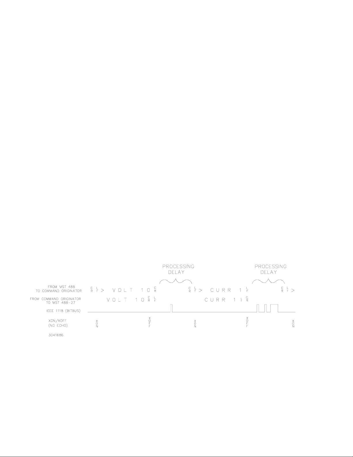
3.3.3 RS 232 IMPLEMENTATION
The following paragraphs are provided to help the user understand how the RS 232 serial interface is implemented in the MST 488-27. Since the RS 232 protocol does not use a parity bit, the
echo mode is the default method used to ensure reliable communication between the command
originator (computer) and the MST 488-27 power supply controller, thus avoiding a more complex “handshake” protocol.
When the MST 488-27 controller is in the RS 232 echo mode it returns all data sent to the host
controller. The MST 488-27 provides two additional options that allow handshake communication: the Prompt method and the XON XOFF method. In standard echo mode the controller
must verify that each character is echoed back by the MST 488-27. As shown in Figure 3-1,
there are times when the MST 488-27 does not echo back the character from the controller,
requiring that the controller resend the character. By using the handshake options (prompt and
XON XOFF) the host controller can ensure that serial data interrupts occurring after parsing of
the incoming message do not result in lost data.
Figure 3-1 illustrates the default echo mode, the prompt method and the XON XOFF method
described in the following paragraphs.
FIGURE 3-1. RS 232 IMPLEMENTATION
Only four control characters (characters between 00H and 1FH) are acknowledged by the power
supply:
• Carriage Return (CR, 0D
• Line Feed (LF, 0A
)
H
• Back Space (BS, 08
• Escape (ESC, 01B
H
)
H
)
H
)
3-4
MST488-27 013004
Page 31

BS deletes the last character entered, with the exception of CR or LF characters. Either the CR
or LF character acts as the line terminator, initiating parsing of the ASCII data sent to the MST
488-27 by the command originator. When the line is parsed and the commands are sent to the
individual power supplies via the IEEE 1118 bus, the MST 488-27 sends the line terminator
sequence CR LF to the command originator.
The ESC character is used for synchronization, causing the MST 488-27 to reset its input buffer
and return a CR LF sequence.
All non-control characters are sent via the serial port of the command originator. The control
character BS is echoed as BS Space BS. Only the first control character is returned in response
to either a CR LF or LF CR character sequence (see Figure 3-1).
3.3.3.1 ECHO MODE
Echo mode is the default method of ensuring data is transferred without errors. Each byte (character) is echoed back to the sender where it is verified as the same character that was just sent.
If the character is incorrect or missing, the sender sends the character again until the correct
character is verified as having been received.
All non-control characters are sent via the serial port of the command originator. The control
character BS is echoed as BS Space BS. Only the first control character is returned in response
to either a CR LF or LF CR character sequence (see Figure 3-1).
3.3.3.2 PROMPT METHOD
The command originator sends a message line (command) to the MST 488-27 and waits until
the prompt sequence CR LF > (3E
sequence CR LF > to the command originator indicating the power supply is ready to receive
the next command and data will not be lost. The prompt method is similar to the echo method
described above, except that the command originator does not have to compare each character
and repeat any characters dropped while the IEEE 1118 bus (BITBUS) is active. The operation
of the MST 488-27 is identical for echo mode and prompt mode; implementation of prompt
mode is at the command originator.
3.3.3.3 XON XOFF METHOD
The XON XOFF method allows the MST 488-27 to control when the command originator is
allowed to send data. The command originator can only send data after the XON (transmission
on) character (011
H
receiving the XOFF (transmission off) character (013
received before sending additional data.
Control characters, either CR or LF, are returned as XOFF CR if echo mode is on, and as XOFF
if echo mode is off. XOFF stops data from the command originator and the MST 488-27 returns
the normal sequence of CR LF (if echo mode is enabled).
, 6210) is received. The MST 488-27 sends the prompt
H
) has been received; the command originator stops sending data after
), and waits until the XON character is
H
MST488-27 013004
3-5
Page 32

3.3.4 PROGRAMMING TECHNIQUES TO OPTIMIZE POWER SUPPLY PERFORMANCE
Kepco's auto-crossover digital supplies can operate in either voltage mode with current limit, or
current mode with voltage limit. The operating mode is determined by the voltage and current
commands received, as well as the load. Each time voltage and current commands are
received, the unit must evaluate the commands and the load conditions to determine the proper
operating mode. Reducing the number of times this evaluation must be made is desirable
because Kepco's digital auto-crossover supplies employ two separate feedback loops. Each
time there is a potential mode change, there is always an uncontrolled period of a few milliseconds while the two feedback loops compete for control of the output. By changing only the
active parameter (e.g., voltage for voltage mode), there is no doubt as to what the operating
mode will be, so the unit is never uncontrolled, response is quick and no transients are possible.
Recommended programming techniques are:
1. Minimize programmed mode (voltage or current) changes. Unless absolutely required by the
test parameters, allow the power supply to automatically switch modes as determined by the
load. This will improve response time and reduce undesirable transients. For those power
supplies that employ relays (Kepco's MBT with "R" option, MAT and MST) this will also
increase the life of the relay.
2. Once the mode (voltage or current) is programmed, program the active parameter to zero
and the complementary limit parameter to the maximum anticipated for application. Then
program only the active parameter. The active parameter is the parameter that controls the
output, e.g., voltage controls the output in voltage mode.
3. Never program both the active and complementary limit parameter to zero. This can result in
long response times. Set the active parameter to zero and the complementary limit parameter to a minimum, e.g., 10% of maximum, to ensure that the active mode is defined.
3.4 SCPI PROGRAMMING
SCPI (Standard Commands for Programmable Instruments) is a programming language conforming to the protocols and standards established by IEEE 488.2 (reference document ANSI/
IEEE Std 488.2, IEEE Standard Codes, Formats, Protocols, and Common Commands). SCPI commands are sent to the MST 488-27 controller as output strings within the selected programming
language (PASCAL, BASIC, etc.) in accordance with the manufacturer’s requirements for the
particular GPIB interface card used.
Different programming languages (e.g., BASIC, C, PASCAL, etc.) have different ways of representing data that is to be put on the IEEE 488 bus. It is up to the programmer to determine how
to output the character sequence required for the programming language used. Address information (GPIB address) must be included before the command sequence. (See PAR. 2.2.1 to
establish the MST 488-27 controller GPIB address.)
NOTE: Although some basic information is provided, the procedures in this manual assume
that programming of the unit using SCPI commands will by done by personnel who are
experienced programmers and understand the protocols required by SCPI and IEEE
488.2.
3-6
MST488-27 013004
Page 33

3.4.1 SCPI MESSAGES
There are two kinds of SCPI messages: program messages from controller to power supply,
and response messages from the power supply to the controller. Program messages consist of
one or more properly formatted commands/queries and instruct the power supply to perform an
action; the controller may send a program message at any time. Response messages consist of
formatted data; the data can contain information regarding operating parameters, power supply
state, status, or error conditions.
3.4.2 COMMON COMMANDS/QUERIES
Common commands and queries are defined by the IEEE 488.2 standard to perform overall
power supply functions (such as identification, status, or synchronization) unrelated to specific
power supply operation (such as setting voltage/current). Common commands and queries are
preceded by an asterisk (*) and are defined and explained in Appendix A (see Table 3-4). Refer
also to syntax considerations (PARs 3.4.3 through 3.4.6).
3.4.3 SCPI SUBSYSTEM COMMAND/QUERY STRUCTURE
Subsystem commands/queries are related to specific power supply functions (such as setting
output voltage, current limit, etc.) Figure 3-2 is a tree diagram illustrating the structure of SCPI
subsystem commands used in the MST 488-27 controller with the “root” at the left side, and
specific commands forming the branches. The subsystem commands are defined and
explained in Appendix B (see Table 3-4).
ROOT : (colon)
INITiate
[:IMMediate]
:CONTinuous
INSTrument
:CATalog
:NSELect
:SELect
:STATe
MEASure
:CURRent?
:VOLTage?
OUTPut
[:STATe]
[SOURce:]
VOLTage
[:LEVel]
[:IMMediate]
:TRIGgered
CURRent
[:LEVel]
[:IMMediate]
:TRIGgered
FUNCtion
:MODE
STATus
:OPERation
:CONDition?
:ENABle
[:EVENt]?
:PRESet
:QUEStionable
:CONDition?
:ENABle
[:EVENt]?
:INSTrument?
:ENB
:ISUM
:INSTrument1?
:ENB
:INSTrument2?
:ENB
SYSTem
:COMMunication
:GPIB:ADDRess
:SERial
:BAUD
:ECHO
:PACE
:PROM
:ERRor?
:CODE?
:ALL?
:LANGuage
:SET
:VERSion?
MST488-27 013004
FIGURE 3-2. TREE DIAGRAM OF SCPI COMMANDS USED WITH MST 488-27 CONTROLLER
3-7
Page 34

3.4.4 PROGRAM MESSAGE STRUCTURE
SCPI program messages consist of one or more message units ending with a terminator. The terminator is not part of the syntax; it is defined by the way your programming language indicates
the end of a line. The message unit is a keyword consisting of a single command or query word
followed by a terminator (e.g., CURR?<newline> or TRIG<end-of-line>). The message unit may
include a data parameter after the keyword separated by a space; the parameter is usually
numeric (e.g., CURR 5<newline>), but may also be a string (e.g., OUTP ON<newline>). Figure
3-3 illustrates the message structure, showing how message units are combined. The following
subparagraphs explain each component of the message structure.
NOTE: An alternative to using the message structure for multiple messages defined in the fol-
lowing paragraphs is to send each command as a separate line. In this case each command must use the full syntax shown in Appendix B.
TABLE 3-4. SCPI COMMAND INDEX
COMMAND
*CLS A.2 INST:SEL, ? B.7, B.8 STAT:QUES? B.28
*ESE A.3 INST:STAT B.9 STAT:QUES:COND? B.29
*ESE? A.4 MEAS:CURR? B.10 STAT:QUES:ENAB B.30
*ESR? A.5 MEAS:VOLT? B.11 STAT:QUES:ENAB? B.31
*IDN? A.6 OUTP:[STAT] B.12 STAT:QUES:INST[1]? B.32
PAR.
REFERENCE
COMMAND
PAR.
REFERENCE
COMMAND
PAR.
REFERENCE
*OPC A.7 OUTP:[STAT}? B.13 STAT:QUES:INST2? B.33
OPC? A.8 [SOUR]:CURR B.14 STAT:QUES:INST[1]:ENAB, ? B.34, B.35
OPT? A.9 [SOUR]:CURR? B.15 STAT:QUES:INST2:ENAB, ? B.36, B.37
*RST A.10 [SOUR]:CURR:TRIG B.16 STAT:QUES:INST:ISUM? B.38
*SRE A.11 [SOUR]:CURR:TRIG? B.17 STAT:QUES:INST:ISUM:ENAB, ? B.39, B.40
*SRE? A.12 [SOUR]:VOLT B.18 SYS:COMM:GPIB:ADDR B.41
*STB? A.13 [SOUR]:VOLT? B.19 SYST:COMM:SER:BAUD B.42
*TRG A.14 [SOUR]:VOLT:TRIG B.20 SYST:COMM:SER:ECHO B.43
*TST A.15 [SOUR]:VOLT:TRIG? B.21 SYST:COMM:SER:PACE B.44
*WAI A.16 [SOUR]:FUNC:MODE B.22 SYST:COMM:SER:PROM B.45
INIT[:IMM] B.2 STAT:OPER:COND? B.23 SYST:ERR B.46
INIT:CONT B.3 STAT:OPER:ENAB B.24 SYST:LANG B.47
INIT:CONT? B.4 STAT:OPER:ENAB? B.25 SYST:SET B.48
INST:CAT B.5 STAT:OPER? B.26 SYST:VERS? B.49
INST:NSEL B.6 STAT:PRES B.27
3.4.4.1 KEYWORD
Keywords are instructions recognized by a decoder within the MST 488-27 controller, referred to
as a “parser.” Each keyword describes a command function; all keywords used by the MST 48827 controller are listed in Figure 3-2.
3-8
MST488-27 013004
Page 35

Each keyword has a long form and a short form. For the long form the word is spelled out completely (e.g. STATUS, OUTPUT, VOLTAGE, and TRIGGER are long form keywords). For the
short form only the first three or four letters of the long form are used (e.g., STAT, VOLT, OUTP,
and TRIG). The rules governing short form keywords are presented in Table 3-5.
You must use the rules described in Table 3-5 when using keywords. Using an arbitrary short
form such as ENABL for ENAB (ENABLE) or IMME for IMM (IMMEDIATE) will result in an error.
Regardless of which form chosen, you must include all the letters required by that form.
To identify the short form and long form in this manual, keywords are written in upper case letters to represent the short form, followed by lower case letters indicating the long form (e.g.,
IMMediate, EVENt, and OUTPut). The parser, however, is not sensitive to case (e.g., outp,
OutP, OUTPUt, ouTPut, or OUTp are all valid).
TABLE 3-5. RULES GOVERNING SHORTFORM KEYWORDS
IF NUMBER OF LETTERS IN
LONGFORM KEYWORD IS:
4 OR FEWER (DOES NOT MATTER) ALL LONG FORM LETTERS MODE
5 OR MORE
KEYWORD
ROOT SPECIFIER
MESSAGE UNIT SEPARATOR
DATA
DATA SEPARATOR
KEYWORD
KEYWORD SEPARATOR
AND FOURTH LETTER
IS A VOWEL?
NO
YES
THEN SHORT FORM
CONSISTS OF:
THE FIRST FOUR
LONG FORM LETTERS
THE FIRST THREE
LONG FORM LETTERS
DATA SEPARATOR
DATA
EXAMPLES
MEASure, OUTPut, EVENt
LEVel, IMMediate, ERRor
MESSAGE UNIT SEPARATOR
ROOT SPECIFIER
KEYWORD
QUERY INDICATOR
KEYWORD
MST488-27 013004
MESSAGE TERMINATOR
CURR:LEV 3.5;:OUTP ON;:CURR?<NL>
MESSAGE UNIT
FIGURE 3-3. MESSAGE STRUCTURE
3-9
Page 36

3.4.4.2 KEYWORD SEPARATOR
If a command has two or more keywords, adjacent keywords must be separated by a colon (:)
which acts as the keyword separator (e.g., CURR:LEV:TRIG). The colon can also act as a root
specifier (paragraph 3.4.4.7).
3.4.4.3 QUERY INDICATOR
The question mark (?) following a keyword is a query indicator. This changes the command into
a query. If there is more than one keyword in the command, the query indicator follows the last
keyword. (e.g., VOLT? and MEAS:CURR?).
3.4.4.4 DATA
Some commands require data to accompany the keyword either in the form of a numeric value
or character string. Data always follows the last keyword of a command or query (e.g.,
VOLT:LEV:TRIG 14 or SOUR:VOLT? MAX
Some data is required to be boolean. Boolean data represents either an on or off condition. The
MST 488-27 accepts either ON or 1 for the true (on) state and either OFF or 0 for the false (off)
state (e.g. OUTPUT OFF is the same as OUTPUT 0).
3.4.4.5 DATA SEPARATOR
Data must be separated from the last keyword by a space (e.g., VOLT:LEV:TRIG 14 or
SOUR:VOLT? MAX
3.4.4.6 MESSAGE UNIT SEPARATOR
When two or more message units are combined in a program message, they must be separated
by a semicolon (;) (e.g., VOLT 15;MEAS:VOLT? and CURR 12; CURR:TRIG 12.5).
3.4.4.7 ROOT SPECIFIER
The root specifier is a colon (:) that precedes the first keyword of a program message. This
places the parser at the root (top left, Figure 3-2) of the command tree. Note the difference
between using the colon as a keyword separator and a root specifier in the following examples:
VOLT:LEV:IMM 16 Both colons are keyword separators.
:CURR:LEV:IMM 4 The first colon is the root specifier, the other two are keyword separators.
VOLT:LEV 6;:CURR:LEV 15 The second colon is the root specifier, the first and third are keyword separators
:INIT ON;:TRIG;:MEAS:CURR?;VOLT? The first three colons are root specifiers.
3.4.5 ADDRESSING MULTIPLE POWER SUPPLIES
Power supplies on the IEEE 1118 bus are selected by node address, also referred to as node
number or channel number. Refer to the applicable manuals for the power modules connected
to the IEEE 1118 bus to set each power module to a unique node number, from 1 to 31 (a maximum of 27 power modules may be connected to the bus).
3-10
The node number may follow any part of a SCPI command. Note that there must be no space
preceding the node number
MST488-27 013004
Page 37

e.g., meas2:volt? or meas:volt2? both measure output voltage of the power supply at node
number 2.
e.g., func3:mode volt or func:mode3 volt both set the power supply at node number 3 to
commanded voltage mode.
e.g., stat1:ques? or stat:ques1? or stat:ques:cond1? all read Questionable Register
status of the power supply at node number 1.
Upon power turn-on, commands sent without a node (channel) number will go to the default
node address (1) until another node number is specified. Once another node number is specified, the new number becomes the default until another is specified.
NOTE: An alternate means of selecting the node, is to use IEEE 488 secondary addressing,
where the secondary address is the power supply node address (refer to PAR. 2.2.2 to
enable this feature).
The node selected can also be changed using the INSTrument:SELect <N> command.
This allows subsequent commands to operate on the specified node (e.g. INST:SEL 10
causes node 10 to be selected).
3.4.6 UNDERSTANDING THE COMMAND STRUCTURE
Understanding the command structure requires an understanding of the subsystem command
tree illustrated in Figure 3-2. The “root” is located at the top left corner of the diagram. The
parser goes to the root if:
• a message terminator is recognized by the parser
• a root specifier is recognized by the parser
Optional keywords are enclosed in brackets [ ] for identification; optional keywords can be omitted and the power supply will respond as if they were included in the message. The root level
keyword [SOURce] is an optional keyword. Starting at the root, there are various branches or
paths corresponding to the subsystems. The root keywords for the MST 488-27 controller are
:INITiate, :MEASure, :OUTPut, [:SOURce], :STATus, and :SYSTem. Because the [SOURce]
keyword is optional, the parser moves the path to the next level, so that VOLTage, CURRent,
and FUNCtion commands are at the root level.
Each time the parser encounters a keyword separator, the parser moves to the next indented
level of the tree diagram. As an example, the STATus branch is a root level branch that has
three sub-branches: OPERation, PRESet, and QUEStionable. The following illustrates how
SCPI code is interpreted by the parser:
STAT:PRES<NL>
The parser returns to the root due to the message terminator.
STAT:OPER?;PRES<NL>
The parser moves one level in from STAT. The next command is expected at the level defined
by the colon in front of OPER?. Thus you can combine the following message units
STAT:OPER? and STAT:PRES;
STAT:OPER:COND?;ENAB 16<NL>
After the OPER:COND? message unit, the parser moves in one level from OPER, allowing the
abbreviated notation for STAT:OPER:ENAB.
MST488-27 013004
3-11
Page 38

3.4.7 PROGRAM MESSAGE SYNTAX SUMMARY
• Common commands begin with an asterisk (*).
• Queries end with a question mark (?).
• Program messages consist of a root keyword and, in some cases, one or more message
units separated by a colon (:) followed by a message terminator. Several message units
of a program message may be separated by a semicolon (;) without repeating the root
keyword.
• If a program message has more than one message unit, then a colon (:) must precede
the next keyword in order to set the parser back to the root (otherwise the next keyword
will be taken as a subunit of the previous message unit).
e.g., the command meas:volt?;curr? will read output voltage and output current
since both volt? and curr? are interpreted as subunits of the meas command.
• Several commands may be sent as one message; a line feed terminates the message.
Commands sent together are separated by a semicolon (;). The first command in a message starts at the root, therefor a colon (:) at the beginning is not mandatory.
e.g., the command meas:volt?;:curr? will read output voltage and programmed current since the colon preceding curr? indicates that curr? is not part of the meas command and starts at the root.
• UPPER case letters in mnemonics are mandatory (short form). Lower case letters may
either be omitted, or must be specified completely (long form)
e.g., INSTrument (long form) has the same effect as INST (short form).
• Commands/queries may be given in upper/lower case (long form)
e.g., SoUrCe is allowed.
• Text shown between brackets [] is optional.
e.g., :[SOUR]VOLT:[LEV] TRIG has the same effect as :VOLT TRIG
3.4.8 STATUS REPORTING
The status reporting of the MST 488-27 follows the SCPI and IEEE 488.2 requirements. The
serial poll response of the MST 488-27 provides summary bits of the status and error reporting
system. The simplest status report is the command valid reporting and data availablity, This successful decoding of a command string generates no error and is indicated by the bit 3 of the
serial poll response being a zero. The setting of bit 4 in the status byte indicates data is available to the controller in response a command query message.
3.4.8.1 STATUS REPORTING STRUCTURE
The status reporting of the MST 488-27 uses four status registers, illustrated in Figure 3-4.
These registers are the Questionable, Operation, Standard Event and Service Request registers. The Questionable and Operation registers are 16 bit registers and the Standard Event and
Service Request registers are 8 bits. These four registers are referred to as condition registers.
Each of the four condition registers is associated with two related registers: an event register
which holds unlatched events reported in realtime by the instrument and is cleared by reading
the register, and an enable register which allows the contents of the event register to be passed
through to set the associated condition register.
3-12
MST488-27 013004
Page 39

A zero to one transition of a condition register is added to the event register if the specific bit in
the enable register is also a 1. Reading an event register clears all of the bits found in the event
register. If any bits are set in an event register, the following condition register bit is then set.
For example, if the STAT:QUES:ENB (enable) register has bit 0 set and a voltage error is
detected, the event registers bit 0 is set. The 1 in the event register causes bit 3 of the status
byte to be asserted. The Service Request register is ANDed with its enable register for all bits
except bit 6. The result is placed in bit 6 of the Service Request register. If bit 6 is a 1 (true), it
causes the MST 488-27 to assert the SRQ line to the host controller.
Figure 3-4 also shows that if the error/event queue is not empty, bit 3 is set in the Service
Request register and bit 4 indicates that a message is available in the output buffer.
3.4.8.2 OPERATIONAL STATUS REGISTER
The OPERational condition register contains conditions which are a part of the instrument’s normal operation. The definition of each of these bits (condition register) is as follows:
• 1 through 7 - Not Used — always zero.
• 8 - Constant Voltage — 1 indicates the instrument is in constant voltage mode.
• 9 - Relay — 1 indicates the power supply relay is closed.
• 10 - Constant Current — 1 indicates the instrument is in constant current mode.
• 11 through15 - Not Used — always zero.
3.4.8.3 QUESTIONABLE STATUS REGISTER
The QUEStionable condition register (see Figure 3-4) contains status bits representing data/signals which give an indication of the quality of various aspects of the signal.
A bit set in the QUEStionable condition register indicates that the data currently being acquired
or generated is of questionable quality due to some condition affecting the parameter associated with that bit.
• 8 - Voltage Mode — 1 indicates the instrument is in Voltage mode.
• 9 - Relay — 1 indicates the power supply relay is closed, unit is supplying power at output terminals.
• 10 - Current Mode — 1 indicates the Power Supply is in Current mode. Changes in this
bit do not affect the event register.
• 14 - Command warning — This bit indicates a non-fatal warning that relates to the
instrument’s interpretation of a command, query, or on or more parameters of a specific
command or query. The power supply sets this bit for
– MEAS:VOLT? 10,1 — The 10 is the number of digits and the 1 is the range. Since
this capability is not implemented in Kepco power supplies, the Command Warning
bit is set.
– INST:SEL 2 sent to a single power supply. Trying to select unit 2 when only one
power supply is connected causes the Command Warning bit to be set.
MST488-27 013004
3-13
Page 40

FIGURE 3-4. STATUS REPORTING STRUCTURE
3.4.8.4 MULTIPLE LOGICAL INSTRUMENTS
The MST 488-27 is a SCPI device that supports multiple logical instruments; it allows a choice
between two methods of status reporting. The status reporting default upon powerup treats the
unit as a single channel instrument. When multiple channels are in use, a SCPI compliant status
structure can be selected which provides an INSTrument summary status register and an individual instrument ISUMmary for each logical instrument. These registers are equivalent to the
Status Questionable register of a single channel instrument and are also found in the STATus
3-14
MST488-27 013004
Page 41
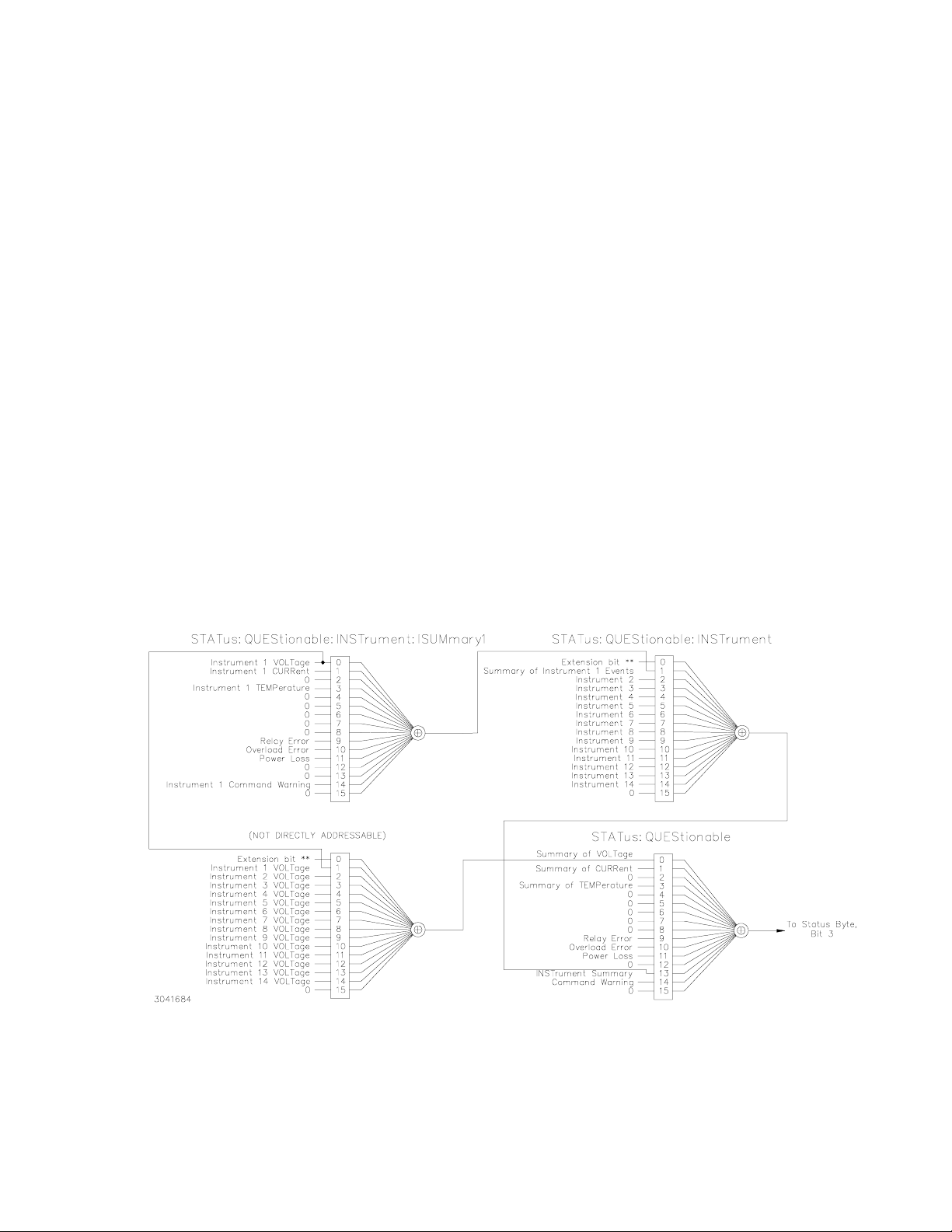
Questionable register for the selected channel. The contents of the STATus Questionable register can also contain the summary of all instruments as shown in Figure 3-5.
The selection of the status reporting structure is controlled by the SYStem:SET SI (Instrument
Structure) command, either SI0 (off) or SI1 (on). The power-up default is the off condition. To
enable the SCPI compliant mode of operation for multiple logical instruments the user must
send SYSTem:SET SI1 to the MST 488-27 during initialization. The SI1 state is not remembered when the unit is turned off. To return to the standard method of reporting the selected
device’s status without turning the unit off, send SYSTem:SET SI0.The state of the power
power supply upon power up for language (SCPI/CIIL), compatibility and GPIB addressing is
selected by DIP switches P1 and P2 (see PAR. 2.2.2 and Table 2-2).
When the MST 488-27 is set up for SCPI compliant status reporting for multiple channels, the
specific instrument’s Questionable register is found in the STAT:QUES:INST:ISUM<n> register.
This register has the same bit structure as the single channel Questionable register. The ISUM
enable register is ANDed with the bits of the channel’s ISUM register and its bit is placed in the
INST register. The Questionable register bits are the logical ORing of all channels’ Questionable
ISUM register. This is shown in Figure 3-5.
The ISUMmary registers set the INSTrument register, which in turn sets bit 13 of the QUEStionable or OPERation status register. This is shown pictorially in Figure 3-5.
The STATUS:QUESTIONABLE and STATUS:QUESTIONABLE:CONDITION registers are the
same in this mode of status reporting. The condition register indicates the status of the various
event registers and bits set are only cleared if the source of the bit is cleared.
FIGURE 3-5. EXPANSION OF QUESTIONABLE REGISTER FOR MULTIPLE LOGICAL INSTRUMENTS
MST488-27 013004
3-15
Page 42

3.4.9 SCPI PROGRAM EXAMPLE
Figure 3-6 is an example of a program using SCPI commands to program an MST Power Supply. The program illustrated is for a configuration using an IBM PC or compatible with a National
Instruments GPIB interface card. (It will be necessary to consult the manufacturer’s data to
achieve comparable functions with an interface card from a different manufacturer.) This program sets output voltage (Voltage mode) or voltage limit (Current mode) to 5V, and current limit
(Voltage mode) or output current (Current mode) to 1A, then reads the measured (actual) voltage and current, then prints the measurements.
/**************************************************************************/
/* Sample Program For KEPCO power supply, using National Instruments */
/* GPIB interface card and IBM PC or compatible computer */
/**************************************************************************/
#include <stdio.h>
#include "decl.h"
char rd_str[80]; // Input buffer
char dat_str[80]; // Output buffer
int bd,adr;
main() {
adr = ibfind("DEV6"); // Open DEV6 (defined by IBCONF)
bd = ibfind ("GPIB0"); // Open GPIB card
ibsic (bd); // Send Interface Clear
ibsre(bd,1); // Set remote line true
strcpy(dat_str,"VOLT 5;CURR 1"); // Define a set command
strcat(dat_str,"\r\n"); // Append delimiter
ibwrt(adr,dat_str,strlen(dat_str)); // Send string to power supply
strcpy(dat_str,"MEAS:VOLT?;CURR?"); // Define a measure command
strcat(dat_str,"\r\n"); // Append delimiter
ibwrt(adr,dat_str,strlen(dat_str)); // Send string to power supply
strset(rd_str,'\0'); // Clear input buffer
ibrd(adr,rd_str,64); // Read result of measure
printf("received : %s\n",rd_str); // Print voltage and current
}
FIGURE 3-6. TYPICAL EXAMPLE OF MST 488-27 CONTROLLER PROGRAM
3.5 CIIL PROGRAMMING
The CIIL command language is used on early models of Kepco power supplies and controllers.
The command functions are included here for compatibility with other equipment programmed
with CIIL commands. The CIIL command set for the MST 488-27 Controller is defined and
explained in Appendix C.
USING SCPI COMMANDS
3-16
MST488-27 013004
Page 43

APPENDIX A - IEEE 488.2 COMMAND/QUERY DEFINITIONS
A.1 INTRODUCTION This appendix defines the IEEE 488.2 common commands and queries used with
the MST 488-27 Controller. Common commands and queries are preceded by an asterisk (*)
and are defined and explained in Figures A-1 through A-14, arranged in alphabetical order.
Table A-1 provides a quick reference of all IEEE 488.2 common commands and queries used in
the MST 488-27 Controller.
TABLE A-1. IEEE 488.2 COMMAND/QUERY INDEX
COMMAND PAR. COMMAND PAR.
*CLS A.2 *RST A.10
*ESE, ? A.3, A.4 *SRE, ? A.11, A.12
*ESR? A.5 *STB? A.13
*IDN? A.6 *TRG A.14
*OPC, ? A.7, A.8 *TST? A.15
*OPT A.9 *WAI A.16
A.2 *CLS — CLEAR STATUS COMMAND
Syntax: *CLS
Description:
Clears status data.
without affecting the corresponding Enable Registers: Standard Event Status Register (ESR), Operation Status Event Register, Questionable Status Event Register, and Status Byte Register (STB).
Related commands: *OPC *OPC?. (See example, Figure A-1.)
Clears the error queue of the instrument. It also clears the following registers
A.3 *ESE — STANDARD EVENT STATUS ENABLE COMMAND
Syntax: *ESE <integer> where <integer> = positive whole number: 0 to 255 per Table A-2.
Default Value: 0
Description:
This command programs the standard Event Status Enable register bits.
as a mask to determine which events of the Event Status Register (ESR) are allowed to set the ESB
(Event Summary Bit) of the Status Byte Register. Enables the Standard events to be summarized in
the Status Byte register (1 = set = enable function, 0 = reset = disable function). All of the enabled
events of the standard Event Status Enable register are logically ORed to cause ESB (bit 5) of the Sta-
.
tus Byte Register to be set (1 = set = enable, 0 = reset = disable)
(See example, Figure A-1.)
TABLE A-2. STANDARD EVENT STATUS ENABLE REGISTER AND
STANDARD EVENT STATUS REGISTER BITS
CONDITION PON NU CME EXE DDE QUE NU OPC
BIT 76543210
VALUE 128 64 32 16 8 4 2 1
PON Power On
NU (Not Used)
CME Command Error
EXE Execution Error
DDE Device Dependent Error
QUE Query Error
OPC Operation Complete
*CLS
*ESE
The contents function
A.4 *ESE? — STANDARD EVENT STATUS ENABLE QUERY
Syntax: *ESE? Return value: Integer> value per Table A-2.
MST488-27 013004
*ESE?
A-1
Page 44

Description: Returns the mask stored in the Standard Event Status Enable Register. Contents of Standard
Event Status Enable register (*ESE) determine which bits of Standard Event Status register (*ESR)
are enabled, allowing them to be summarized in the Status Byte register (*STB). All of the enabled
events of the Standard Event Status Enable Register are logically ORed to cause ESB (bit 5) of the
Status Byte Register to be set (1 = set = enable function, 0 = reset = disable function). (See example,
Figure A-1.)
A.5 *ESR? — EVENT STATUS REGISTER QUERY
Syntax: *ESR?
Return value: <integer> (Value = contents of Event Status register as defined in Table A-2.)
Description: Causes the power supply to return the contents of the Standard Event Status register. After it
has been read, the register is cleared.
defined in Table A-2 (1 = set, 0 = reset). The error bits listed in Table A-2 are also related to error
codes produced during parsing of messages and to errors in the power supply.
• Any 1xx type error sets the Command error bit (5) see.
• Any 2xx type error sets the Execution error bit (4).
• Any 3xx type error sets the Device error bit (3). The Device error bit will be set when Current Error
or Voltage Error is detected and the corresponding Status Questionable bit is set (see PAR. B.28).
• Any 4xx type error sets the Query error bit (2).
Related Commands: *CLS, *ESE, *OPC. (See example, Figure A-1.)
The Standard Event Status register bit configuration is
A.6 *IDN? — IDENTIFICATION QUERY
:
Syntax
Description: Identifies the instrument. This query requests identification. The string contains the manufacturer
*IDN?
Return value: Character string
name, model, SN, firmware revs. The SN field is normally used for the serial #, but since serial #s are
not stored in memory , the channel # is given instead. The firmware revision consists of the controller
rev. and power module rev. seperated by a ‘-'. If no module is present at the selected channel, PSC
(Power Supply Controller) is given as the model. Supported models include MAT, MBT, and MST The
character string contains the following fields: <Manufacturer>, <Model>, <Serial Number>, <Firmware
revision> where: <Manufacturer> = KEPCO, <Model> = MST 488-27, <Serial Number> =
MM,DD,YY-SSS (MM - month, DD - day, YY - year, SSS - serial number in that day) <Firmware revision>=n.m (n.m revision, e.g, 1.0) (See example, Figure A-1.)
*ESR?
*IDN?
The model identified in the *IDN? query after power up of the controller is the device connected to the
BITBUS with an address of 1. If no device is set to be address 1 then the power up IDN string
returned will contain the model identifier of PSC. The model identifier reflects the type of power supply at a specific BITBUS address. figure B-2 shows an example of the model identifier after specifying
any device.
A.7 *OPC — OPERATION COMPLETE COMMAND
Syntax: *OPC
Description: Causes power supply to set status bit 0 (Operation Complete) when pending operations are
complete This command sets Standard Event Status Register bit 0 (see Table A-2) to “1” when all
previous commands have been executed and changes in output level have been completed. This
command does not prevent processing of subsequent commands, but bit 0 will not be set until all
pending operations are completed. (1 = set = enable function, 0 = reset = disable function). (See
example, Figure A-1.) As an example, the controller sends command(s), then sends *OPC. If controller then sends *ESR?, the power supply responds with either a “0” (if the power supply is busy executing the programmed commands), or a “1” (if the previously programmed commands are complete).
(See example, Figure A-1.)
A-2
*OPC
MST488-27 013004
Page 45

A.8 *OPC? — OPERATION COMPLETE QUERY
Syntax: *OPC?
Return value: <1> (ASCII) placed in output queue when power supply has completed operation.
Description: Indicates when pending operations have been completed.When all pending operations are com-
plete (all previous commands have been executed and changes in output level have been completed)
a “1” is placed in the Output Queue. Subsequent commands are inhibited until the pending operations
are completed. *OPC? is intended to be used at the end of a command line so that the application program can monitor the bus for data until it receives the “1” from the power supply Output Queue. (See
example, Figure A-1.)
*OPC?
A.9 *OPT? — OPTIONS QUERY
Syntax: *OPT?
Returns string determined by power supply model.
Description: Causes the power supply to return an ASCII string which defines the functionality of the power
supply. The functionality is defined as follows:
STRING DATA MEANING
RI1
CHN
DS0
CIIL
*CLS Power supply clears status data.
*ESE 60 Power supply enables bits 5, 4, 3 and 2, allowing command error, execution
*ESE? Returns 60, (value of the mask) verifying that bits 5, 4, 3 and 2 are enabled.
*ES Unknown command will set command error (Bit 5).
*ESR? Returns 32 (bit 5 set), indicating Command Error has occurred since the last
*IDN? Controller returns character string: "KEPCO,MST,1,V3.0-3.0"
*OPC Allows status bit 0 to be set when pending operations complete
VOLT 21;CURR 3 Sets output voltage to 21V, output current to 3A
*ESR Returns 129 (128 + 1, power on, bit 7 = 1, operation complete, bit 1 = 1)
*ESR Returns 0 (event status register cleared by prior *ESR?)
VOLT 15;CURR 5;*OPC? Sets output voltage to 15V, output current to 5A, puts “1” on output bus when
*RST Power supply reset to power on default state.
*SRE 40 When ESB or QUES bits are set (Table A-3), the Request for Service bit will
*SRE? Returns the value of the mask (40).
*STB? For example, the Power supply responds with 96 (64 + 32) if MSS and the
VOLT 25 Power supply voltage commanded to 25V.
VOLT:TRIG 12 Programs power supply voltage to 12V when *TRG received.
INIT Trigger event is initialized.
*TRG Power supply reverts to commanded output voltage of 12V.
*TST? Power supply executes self test and responds with 0 if test completed
Indicates unit has the ability to modify the DCL response.
Indicates multiple channel device is enabled
Display present, no text capability.
Unit supports CIIL commands
error, device dependent error and query error to set the Event Status
Summary bit when an STB command is executed.
time the register was read.
command operations are complete.
be set.
Event Status Byte (Table A-3) summary bit have been set. The power supply
returns 00 if no bits have been set.
successfully, with 1 if test failed.
*OPT?
MST488-27 013004
FIGURE A-1. GPIB COMMANDS
A-3
Page 46

A.10 *RST — RESET COMMAND
Syntax: *RST
Description: Resets power supply to the power on default state. The power supply is programmed to the power
on values of the following parameters: CURR[:LEV][:IMM] = 0, VOLT[:LEV][:IMM] = 0, OUTP[:STAT]
= OFF. If the power supply is in either an overvoltage or overcurrent state, this condition is reset by
*RST. (See example, Figure A-1.)
*RST
A.11 *SRE — SERVICE REQUEST ENABLE COMMAND
Syntax: *SRE<integer> where <integer> = value from 0 - 255 per Table A-3, except bit 6 cannot be pro-
grammed.
Description: Sets the condition of the Service Request Enable register. The Service Request Enable register
determines which events of the Status Byte Register are summed into the MSS (Master Status Summary) and RQS (Request for Service) bits. RQS is the service request bit that is cleared by a serial
poll, while MSS is not cleared when read. A "1" (1 = set = enable, 0 = reset = disable) in any Service
Request Enable register bit position enables the corresponding Status Byte bit to set the RQS and
MSS bits. All the enabled Service Request Enable register bits then are logically ORed to cause Bit 6
of the Status Byte Register (MSS/RQS) to be set. Related Commands: *SRE?, *STB?. (See example, Figure A-1.)
*SRE
TABLE A-3. SERVICE REQUEST ENABLE AND STATUS BYTE REGISTER BITS
OPER Operation Status Summary
CONDITION OPER
BIT 7 6543210
VALUE 128 64 32 16 8 4 2 1
MSS
RQS
ESB MAV QUES
ERR
QUE
NU NU
A.12 *SRE? — SERVICE REQUEST ENABLE QUERY
Syntax: *SRE? Response: <integer> = value from 0 - 255 per Table A-3.
Description: Reads the Service Enable Register. Used to determine which events of the Status Byte Register are
programmed to cause the power supply to generate a service request (1 = set = function enabled, 0 =
reset = function disabled). Related Commands: *SRE, *STB? (See example, Figure A-1.)
MSS Master Status Summary
RQS Request for Service
ESB Event Status Byte summary
MAV Message available
QUES QUEStionable Status Summary
ERR QUE 1 or more errors occurred (see
NU (Not Used)
PAR. B.46)
*SRE?
A.13 *STB? — STATUS BYTE REGISTER QUERY
:
Syntax
Description:
*STB? Response: <integer> value from 0 to 255 per Table A-3.
Reads Status Byte Register without clearing it.
MSS) without clearing it (1 = set = function enabled, 0 = reset = function disabled). The register is
cleared only when subsequent action clears all set bits. MSS is set when the power supply has one
ore more reasons for requesting service. (A serial poll also reads the Status Byte Register, except that
bit 6 = RQS, not MSS; ands RQS will be reset.) Related Commands: *SRE, *SRE?. (See example,
Figure A-1.)
This Query reads the Status Byte Register (bit 6 =
A.14 *TRG — TRIGGER COMMAND
Syntax: *TRG
Description: Triggers the power supply to be commanded to preprogrammed values of output current and
voltage. When the trigger is armed (checked by examining WTG bit in Status Operational Condition
register) *TRG generates a trigger signal. The trigger will change the output of the power supply to the
output voltage and current levels specified by VOLT:TRIG and CURR:TRIG commands and clear the
WTG bit in the Status Operation Condition register. If INIT:CONT has been issued, the trigger
*STB?
*TRG
subsystem is immediately rearmed for subsequent triggers, and the WTG bit is again set to
1. *TRG or GET are both addressed commands (only devices selected as listeners will exe-
A-4
cute the command).
example, Figure A-1.
Related Commands:
)
ABOR, INIT, TRIG, CURR:TRIG, VOLT:TRIG.
MST488-27 013004
(See
Page 47

A.15 *TST? — SELF TEST QUERY
Syntax: *TST? Returned value: 0 or n (0 = pass test, n = fail test )where n = address of failed unit(s)
Description: Power Supply test.This query causes the power supply to do a self test and provide the controller
with pass/fail results. The *TST? command performs the following tasks on relay equipped units:
• Sets output off (disconnects Relays).
• Sets the output to a max positive level, measures the voltage reported to the A to D converter.
• Sets the output to 0, measures the output.
• Swaps the output relays to make the output negative.
• Sets the output to max negative level and measures the output.
• Set output to 0 and sets output relays to positive value.
For power supplies which do not have relays (e.g, MBT and BOP), the levels indicated above will actually appear at the power supply output.
Errors (e.g., voltage error or relay error) are reported over the Bit bus. These errors update flags in the
status Questionable register in the controller. If the power supply’s questionable register is 0, it is considered to have passed and if it is non-zero it has failed. An error on any power supply connected to
the controller is reported as the address of the power supply. If, for example, there are three power
supplies connected and *TST? is executed, all power supplies perform the test and the response will
be 0 if all pass. If device 2 fails, the response would be 2. If devices 2 and 3 fail the response would be
2,3.
*TST?
The user can determine if there was a Relay error or a voltage setting error by sending STAT:QUESn?
to the device, replacing n with the number returned in response to *TST?. For example,
STAT:QUES1? should be sent if the *TST? response was a 1. A voltage error is reported in the questionable register if there is a problem in setting an output.
If the unit fails, it is recommended that the test be executed a second time after reading the
STAT:QUES register. This is recommended because if the error was already set in the status questionable register It is possible for a unit that fails *TST? may pass when retested.
A.16 *WAI — WAIT-TO-CONTINUE COMMAND
Syntax: **WAI Returned value: 0 or 1 (0 = pass test, 1 = fail test)
Description: Causes the power supply to wait until all previously issued commands and queries are com-
plete before executing subsequent commands or queries. This command can be used to guarantee sequential execution of commands and queries. When all pending operations are complete (all
previous commands have been executed, changes in output level have been completed), the WAI
command is completed and execution of subsequent commands can continue.
Example:
VOLT 10;:*WAI;:volt 15 The *WAI command ensures that the power supply output
actually goes to 10V before being set to 15V
*WAI?
MST488-27 013004
FIGURE A-2. USING THE *WAIT-TO-CONTINUE COMMAND
A-5/(A-6 Blank)
Page 48

Page 49

APPENDIX B - SCPI COMMAND/QUERY DEFINITIONS
B.1 INTRODUCTION This appendix defines the SCPI subsystem commands and queries used with
the MST 488-27 Controller. Subsystem commands are defined in PAR. B.2 through B.49,
arranged in groups as they appear in the tree diagram, Figure 3-2. Table B-1 provides a quick
reference of all SCPI subsystem commands and queries used in the Interface Card.
NOTE: Upon power loss, all programmed values/configurations are lost and must be repro-
grammed.
TABLE B-1. SCPI SUBSYSTEM COMMAND/QUERY INDEX
COMMAND PAR. COMMAND PAR.
INIT[:IMM] B.2 STAT:QUES[:EVENT]? B.28
INIT:CONT, ? B.3, B.4 STAT:QUES:COND? B.29
INST:CAT? B.5 STAT:QUES:ENAB, ? B.30, B.31
INST:NSEL B.6 STAT:QUES:INST[1]? B.32
INST:SEL B.7, B.8 STAT:QUES:INST2? B.33
INST:STAT B.9 STAT:QUES:INST[1]:ENAB, ? B.34, B.35
MEAS:CURR? B.10 STAT:QUES:INST2:ENAB, ? B.36, B.37
MEAS:VOLT? B.11 STAT:QUES:INST:ISUM? B.38
OUTP[:STAT], ? B.12, B.13 STAT:QUES:INST:ISUM:ENAB, ? B.39, B.40
[SOUR:]CURR[:LEV][:IMM][:AMP], ? B.14, B.15 SYST:COMM:GPIB:ADDR B.41
[SOUR:]CURR[:LEV]:TRIG[:AMP], ? B.16, B.17 SYST:COMM:SER:BAUD B.42
[SOUR:]VOLT[:LEV][:IMM][:AMP], ? B.18, B.19 SYST:COMM:SER:ECHO B.43
[SOUR:]VOLT[:LEV]:TRIG[:AMP]? B.20, B.21 SYST:COMM:SER:PACE B.44
[SOUR:]FUNC:MODE B.22 SYST:COMM:SER:PROM B.45
STAT:OPER:COND? B.23 SYST:ERR? B.46
STAT:OPER:ENAB, ? B.24, B.25 SYST:LANG B.47
STAT:OPER[:EVENT]? B.26 SYST:SET B.48
STAT:PRES B.27 SYST:VERS? B.49
B.2 INITiate[:IMMediate]
COMMAND
INIT[:IMM]
Syntax: Short Form: INIT:[IMM] Long Form: INITiate[:IMMediate]
Description: Enables a single trigger. If INIT:CONT is OFF, then INIT[:IMM] arms the trigger system for a single
trigger. If INIT:CONT is ON, then the trigger system is continuously armed and INIT[:IMM] is redundant. This command enables a single trigger. A GPIB <GET>, *TRG or command completes the
sequence. Upon receipt of the <GET> or *TRG command, the power supply will return to the programmed values of voltage and current established by the VOLT:TRIG and CURR:TRIG commands.
After a GPIB <GET> or *TRG command has been received, subsequent GPIB <GET>, *TRG commands have no effect unless preceded by INIT or INIT:CONT ON. Related Commands: <GET>,
*RST, *TRG. (See example, Figure B-3.)
B.3 INITiate:CONTinuous COMMAND
INIT:CONT
Syntax: Short Form: INIT:CONT {ON | OFF} or {1 | 0} ( 1 = on, 0 = off)
Long Form: INITiate:CONTinuous {ON | OFF} or {1 | 0} ( 1 = on, 0 = off)
Description: INIT:CONT ON enables continuous triggers.; INIT:CONT OFF disables continuous triggers. If
INIT:CONT is OFF, then INIT[:IMM] arms the trigger system for a single trigger. If INIT:CONT is ON,
then the trigger system is continuously armed and INIT[:IMM] is redundant. Executing *RST command
sets INIT:CONT to OFF. (See example, Figure B-3.)
MST 488-27 013004
B-1
Page 50

B.4 INITiate:CONTinuous
Syntax: Short Form: INIT:CONT? Long Form: :INITiate:CONTinuous?
Return Value: 1 or 0
Description: Determines whether continuous triggers are enabled or disabled. Power supply returns value of
INIT:CONT flag: “1” = continuous triggers are enabled (INIT:CONT ON); “0” = continuous triggers
disabled (INIT:CONT OFF). (See example, Figure B-3.)
QUERY
INIT:CONT?
B.5 INSTrument:CATalog
Syntax: Short Form: INST:CAT? Long Form: :INSTrument:CATalog?
Return Value: comma separated string with the instrument numbers found on the bitbus.
Description: Allows the host computer to determine what instruments are on the bitbus. Unlike the *RST com-
mand, this command does not scan possible bitbus addresses to determine if the device is present.
The list contains all channel numbers found and allows the host computer to determine if the MST
power supplies are connected and powered-up (see Figure B-1).
*RST Bitbus is scanned and all supplies are set to 0v, 0c, and Voltage mode
INST:CAT? With three MST's connected to the MST 488 controller the MST 488
INST:CAT? MST 488 returns 1,3
INST:CAT? MST 488 returns 1,3
INST2 Channel 2 restored
INST:CAT? MST 488 returns 1,2,3
INST:CAT? MST 488 returns 1,2
VOLT3 4;:SYST:ERR? MST 488 returns "0240, Hardware not found"
VOLT3 4;:SYST:ERR? Channel 3 restored
INST:CAT? MST 488 returns 1,2,3
QUERY
returns 1,2,3 if their addresses are set to 1, 2 and 3.
*** User turns off supply 2.
*** User turns on supply 2
*** User turns off supply 3
*** User turns on supply 3
INST:CAT?
FIGURE B-1. USE OF INSTrument:CATalog QUERY
B.6 INSTrument[:NSELect] COMMAND
:
Syntax
Description:
Short Form :INST:NSEL <val> Long Form: INSTrument:NSELect <val>
Selects power supply connected to channel number <VAL>; also brings off-line or “locked out”
power supply to on-line status. selects the instrument to which subsequent commands will be
addressed until another channel is selected. Identical to INST:SEL command (see PAR. B.7).
B.7 INSTrument[:SELect] COMMAND
Syntax: Short Form :INST:SEL <val> Long Form: INSTrument:SELect <val>
Description:
Example: STAT:QUES?2 Program reads the Questionable Event Register for power supply on channel 2.
Selects power supply connected to channel number <VAL>; also brings off-line or “locked out”
power supply to on-line status. selects the instrument to which subsequent commands will be
addressed until another channel is selected. The <value> following the command is the channel
(node) number, from 1 to 31. This command is also used to bring a power supply on-line (i.e., the controller recognizes a power supply assigned to a selected channel). In cases where a fault has “locked
out” a power supply (the controller no longer recognizes the power supply assigned to a channel), this
command restores the power supply to the system. (See example, Figure B-5.)
If the power supply responds with 2048 (bit 11) indicating power loss, the power supply will be off-line
and unable to be selected. After the power fault has been corrected, the INST command is sent.
B-2
INST:NSEL
INST:SEL
MST 488-27 013004
Page 51

INST2 The power supply on channel 2 is reset and brought on-line; subsequent commands
will apply to channel 2 until a new channel is selected.
INST? <Value> 2 returned to controller.
B.8 INSTrument[:SELect]? QUERY
Syntax: Short Form :INST:SEL? Long Form: INSTrument:SELect ?
Return value: <VAL> 1 to 31
Description: Used to determine which channel selected.
B.9 INSTrument:STATe COMMAND
Syntax: Short Form :INST:STAT <val> Long Form: INSTrument:STATe <val>
Description: 0 (off) sets output to 0; 1 (on) restores output voltage and current. (See Figure B-2)
Note: Power Supply at address 1 is an MBT 25-14, address 2 is an MST 6-12, and address 4 is a BOP 100-1.
*RST Devices are located on the BITBUS (IEEE 1118) as noted above.
INST:SEL 1;*IDN? Controller returns KEPCO,MBT,1,V4.2-3.0 (Channel 1 selected; device con-
nected to BITBUS channel 1 is MBT 25-14, firmware version 3.0; MBT
firmware version is 4.2).
INST:NSEL 2;*IDN? Controller returns KEPCO,MST,2,V4.2-2.6 (Channel 2 selected; device con-
nected to BITBUS channel 2 is MST 6-12, firmware version 2.6; MBT firmware version is 4.2).
VOLT? MAX Controller returns 6.0E0 indicating a 6 volt unit (MST 6-12 at connected to
channel 2).
VOLT4? MAX;:INST:SEL? Controller returns 1.0E2,4 indicating address 4 is selected and the device
connected to BITBUS channel 4 (BOP 100-1) is a 100 volt unit.
*IDN? Controller returns KEPCO,BOP,4,V4.2-1.1 (Device connected to BITBUS
channel 4 is a BOP with BIT card firmware version 1.1; MBT firmware version is 4.2).
*RST;*IDN? Controller returns KEPCO,MBT,V4.2-3.0 (Channel 1 selected; device con-
nected to BITBUS channel 1 is MBT 25-14, firmware version 3.0; MBT
firmware version is 4.2).
INST:SEL 3;*IDN? Controller returns KEPCO,PSC,1,V4.2 (Channel 3 selected; unknown
device connected to channel 3; MBT firmware version is 4.2).
INST:SEL?
INST:STAT
FIGURE B-2. IDENTIFYING AND SELECTING DEVICES ON BITBUS
B.10 MEASure[:SCALar]:CURRent[:DC]? QUERY
Syntax: Short Form: MEAS[:SCAL]:CURR[:DC]? <boolean>
Long Form: MEASure[:SCALar]:CURRent[:DC]? <boolean>
<boolean> = 0 or 1
Return Value: <num_value> (digits with decimal point and Exponent)
Description: Measures actual current. This query returns the actual value of output current (measured at the out-
put terminals) as determined by the programmed value of voltage and current and load conditions.
NOTE: The SCPI convention for this command allows the controller to establish the range and accuracy of the measurement if nn,nn is added after the question mark; the power supply accepts this format but sets the command warning bit (13) in the status questionable register and ignores the extra
characters. (See example, Figure B-3.)
MST 488-27 013004
MEAS:CURR?
B-3
Page 52

B.11 MEASure[:VOLTage][:SCALar][:DC]?
Syntax: Short Form: MEAS[:SCAL]:VOLT[:DC]? <boolean>
Long Form: MEASure[][:SCALar]:VOLTage[:DC]? <boolean>
<boolean> = 0 or 1
Return Value: <num_value> (digits with decimal point and Exponent)
Description: Measures actual voltage. This query returns the actual value of output voltage (measured at the out-
put terminals) as determined by the programmed value of voltage and current and load conditions.
NOTE: The SCPI convention for this command allows the controller to establish the range and accuracy of the measurement if nn,nn is added after the question mark; the power supply accepts this format but sets the command warning bit (13) in the status questionable register and ignores the extra
characters. (See example, Figure B-3.)
QUERY
MEAS:VOLT?
B.12 OUTPut[:STATe]
Syntax: Short Form: OUTP[:STAT] <boolean> Long Form: OUTPut[:STATe] <boolean>
<boolean>=(0 or OFF, 1 or ON)
OUTP <boolean>(@n1,n2,n3) Open or close multiple channels, n1, n2, n3 = channel numbers
OUTP <boolean>(@n1:n2) Open or close a range of channels, n1 = low, , n2 = high channel number
Description:
Enables or disables the power supply output.
When OUTP OFF is executed, the programmed values of voltage and current are saved, then voltage
and current are programmed to 0. When OUTP ON is executed, the power supply output is restored to
the previously saved programmed values. The saved values of voltage and current can be viewed by
VOLT? and CURR? queries. .Related Commands: OUTP?. (See example, Figure B-3. Multiple channel examples: OUTP OFF(@5,7) closes channels 5 and 7, OUTP ON(@4:7) opens channels 4, 5, 6,
and 7.
B.13 OUTPut[:STATe]
Syntax: Short Form: OUTP[:STAT]? Long Form: OUTPut[:STATe]?
Return Value: <int_value> (0 or 1)
Description:
Indicates whether power supply output is enabled or disabled.
returns 1 if output enabled. Related Commands: OUTP. (See example, Figure B-3.)
COMMAND
QUERY
Upon power up the output is enabled (OUTP ON).
Returns 0 if output disabled,
B.14 [SOURce:]CURRent[:LEVel][:IMMediate][:AMPlitude] COMMAND
Syntax: Short Form: [SOUR:]CURR[:LEV][:IMM][:AMP] <exp_value>
Long Form: [SOURce:]CURRent[:LEVel][:IMMediate][:AMPlitude] <exp_value>
<exp_value> = digits with decimal point and Exponent, e.g., 2.71E+1 for 27.1
OUTP
OUTP?
CURR
Description:
B.15 [SOURce:]CURRent[:LEVel][:IMMediate][:AMPlitude] QUERY
Syntax: Short Form: [SOUR:]CURR[:LEV][:IMM][:AMP]? MIN, MAX
Description: Returns either the programmed value, maximum value, or minimum value of current. The
B-4
Sets programmed current level at power supply output.
a specific value; actual output current will depend on load conditions. If the value exceeds the maximum for the model being programmed, error message -222,”Data out of range” is posted in output
queue. (See example, Figure B-3.)
This command programs output current to
CURR?
Long Form: [SOURce:]CURRent[:LEVel][:IMMediate][:AMPlitude]? MIN, MAX
Return Value:<exp_value> = digits with decimal point and Exponent, e.g., 2.71E+1 for 27.1
CURR? query returns the programmed value of current. Actual output current will depend on load conditions. The CURR?MAX query returns the maximum current allowed for a particular model. CURR?
Returns programmed current value. CURR? MAX returns maximum current allowed for power supply.
CURR? MIN returns minimum current allowed for power supply (always 0). Related Commands:
CURR. (See example, Figure B-3.)
MST 488-27 013004
Page 53

NOTES: 1. The power supply is assumed to be operating in constant voltage (CV) mode.
2 Examples below are intended only to illustrate command functions. Refer to PAR. 3.3.4 for pro-
gramming techniques to optimize performance.
OUTP ON Output enabled.
OUTP? Power supply returns “1” (output enabled).
VOLT 21; CURR 1.5 Power supply output programmed to go to 21V, current limit 1.5A
INIT:CONT ON Continuous triggers enabled.
INIT:CONT? Power supply returns “1.”
VOLT:TRIG 15;CURR:TRIG 3 Power supply output programmed to return to 15V, current limit
3A upon receipt of trigger.
*TRG Power supply output returns to 15V,current limit 3A.
VOLT 21; CURR 5E-2 Power supply output programmed to go to 21V, current limit 0.05A
MEAS:VOLT? If actual value of output voltage is 20.9V, power supply
returns 2.09E+1.
MEAS:CURR? If actual value of output current is 0.0483A, power supply
returns 4.83E-2.
FUNC:MODE? Returns VOLT if power supply operating in constant voltage
mode, CURR for constant current mode.
CURR:TRIG? Returns 3 (current value established by CURR:TRIG.
VOLT:TRIG? Returns 15 (voltage value established by VOLT:TRIG.
*TRG Power supply output returns to 21V, current limit 0.05A.
INIT:CONT 0 Triggers disabled.
INIT:CONT? Power supply returns “0.”
OUTP OFF Output disabled.
OUTP? Returns 0 (output disabled).
MEAS:VOLT? Returns 0. (measured output voltage).
VOLT? Returns 17.(programmed output voltage)/
CURR? Returns 1.5 (programmed current)
CURR? MAX Returns 4 (assuming maximum allowable current for power
supply being addressed is 4A, i.e. ABC 25-4DM).
CURR? MIN Returns 0 (minimum allowable current).
CURR? Returns 1.5, indicating programmed current value = 1.5A.
SYST:VERS? Returns 1997.0.
FIGURE B-3. PROGRAMMING THE OUTPUT
B.16 [SOURce:]CUR Rent:[:LE Vel]TRIG gered[ :AMPlitu de] COMMAND
Syntax: Short Form: [SOUR:]CURR[:LEV]:TRIG[:AMP] <exp_value>
Long Form: [SOURce:]CURRent[:LEVel]:TRIGgered[:AMPlitude] <exp_value>
<exp_value> = digits with decimal point and Exponent, e.g., 2.71E+1 for 27.1
Description:
B.17 [SOURce:]CURRent:[:LEVel]TRIGgered[:AMPlitude]?
Syntax: Short Form: [SOUR:]CURR[:LEV]:TRIG[:AMP]?
Description: Returns the current value established by CURR:TRIG command. (See example, Figure B-3.)
MST 488-27 013004
Programs current value to be transferred to output by *TRG commands.
will depend on load conditions. If the value exceeds the maximum for the model being programmed,
error message -222,”Data out of range” is posted in output queue. Related Commands: CURR. (See
example, Figure B-3.)
QUERY
Long Form: [SOURce:]CURRent[:LEVel]:TRIGgered[:AMPlitude]?
Return Value: <exp_value> = digits with decimal point and Exponent, e.g., 2.71E+1 for 27.1
CURR:TRIG
Actual output current
CURR:TRIG?
B-5
Page 54

NOTES: 1. The power supply is assumed to be operating in constant voltage (CV) mode.
2 Examples below are intended only to illustrate command functions. Refer to PAR. 3.3.4 for
programming techniques to optimize performance.
VOLT 21; CURR 1.1 Power supply programmed to voltage limit 21V, 1.1A.
CURR? Returns 1.1.
CURR 4.2 Power supply output current programmed to 3.3A, error message
-301 posted.
CURR? Returns 3.3.
--- OVERCURRENT CONDITION (1 SECOND) OCCURS.
CURR? Returns small value (approx. 1% of full scale current rating).
CURR 2.5 Power supply output current programmed to 2.5A
--- OVERCURRENT CONDITION (1 SECOND) OCCURS.
(After 10 seconds)
CURR? Returns 2.5.
FIGURE B-4. PROGRAMMING CURRENT
B.18 [SOURce:]VOLTage[:LEVel][:IMMediate][:AMPlitude] COMMAND
Syntax: Short Form: [SOUR:]VOLT[:LEV][:IMM][:AMP] <exp_value>
Long Form: [SOURce:]VOLTage[:LEVel][:IMMediate][:AMPlitude] <exp_value>
<exp_value> = digits with decimal point and Exponent, e.g., 2.71E+1 for 27.1
Description: Sets programmed voltage level at power supply output. This command programs output voltage
to a specific value; actual output voltage will depend on load conditions. If the value exceeds the maximum for the model being programmed, error message -222,”Data out of range” is posted in output
queue. (See example, Figure B-3.
B.19 [SOURce:]VOLTage[:LEVel][:IMMediate][:AMPlitude]? QUERY
Syntax: Short Form: [SOUR:]VOLT[:LEV][:IMM][:AMP]? {MIN | MAX}
Long Form: [SOURce:]VOLTage[:LEVel][:IMMediate][:AMPlitude]? {MIN | MAX}
Description: Identifies programmed voltage, maximum allowable voltage, or miniimum voltage (always 0).
The VOLT? query returns the programmed value of voltage. Actual output voltage will depend on load
conditions. The VOLT?MAX query returns the maximum voltage allowed for a particular model (e.g.,
25V for MST25-8DM). VOLT? MINReturns minimum voltage allowed for power supply (always 0).
Related Commands: VOLT. (See example, Figure B-3
B.20 [SOURce:]VOLTage:[:LEVel]TRIGgered[:AMPlitude] COMMAND
Syntax: Short Form: [SOUR:]VOLT[:LEV]:TRIG[:AMP] <exp_value>
Long Form: [SOURce:]VOLTage[:LEVel]:TRIGgered[:AMPlitude] <exp_value>
<exp_value> = digits with decimal point and Exponent, e.g., 2.71E+1 for 27.1
Description: Programs voltage value to be transferred to output by *TRG commands. Actual output voltage
will depend on load conditions. If the value exceeds the maximum for the model being programmed,
error message -222,”Data out of range” is posted in output queue. (See example, Figure B-3.)
VOLT:TRIG
VOLT
VOLT?
B.21 [SOURce:]VOLTage:[:LEVel]TRIGgered[:AMPlitude]? QUERY
Syntax: Short Form: [SOUR:]VOLT[:LEV]:TRIG[:AMP]?
Long Form: [SOURce:]VOLTage[:LEVel]:TRIGgered[:AMPlitude]?
Return Value: <exp_value> = digits with decimal point and Exponent, e.g., 2.71E+1 for 27.1
Description: Returns value representing voltage value to be programmed by *TRG command established by
VOLT:TRIG command). (See example, Figure B-3.)
B-6
VOLT:TRIG?
MST 488-27 013004
Page 55

B.22 [SOURce:]FUNCtion:MODE COMMAND
Syntax: Short Form:FUNC:MODE {VOLT | CURR}
Long Form: FUNCtion:MODE {VOLT | CURR}
Description: Establishes the operating mode of the power supply. VOLT = Constant Voltage mode (CV).
CURR = Constant Current mode (CC).
FUNC:MODE
B.23 STATus:OPERation:CONDition QUERY
:
Syntax
Description: Returns the value of the Operation Condition Register (see Table B-2). The Operation Condition
Short Form: STAT:OPER:COND? Long Form: STATus:OPERation:CONDition?
Return Value: <int_value> 0 to 1313 (256 + 512 + 1024).
Register contains the programmed mode of the power supply (not the actual condition). Bit set to 1 =
state enabled (active, true); bit reset to 0 = state disabled (inactive, false). (See example, Figure B-5.)
STAT:OPER:COND?
TABLE B-2. OPERATION CONDITION REGISTER, OPERATION ENABLE REGISTER,
AND OPERATION EVENT REGISTER BITS
CONDITION NU CC RLY CV NU NU NU NU
BIT 15-11 10 9 8 7 - 6 5 4 - 1 0
VAL UE
32,768 -
2048
1024 512 256 128 - 64 32 16 -2 1
B.24 STATus:OPEReration:ENABle COMMAND
Syntax: Short Form: STAT:OPER:ENAB <int_value> 0 to 32767 (1 + 32 + 256 + 1024)
Long Form: STATus:OPERation:ENABle <int_value> 0 to 32767 (1 + 32 + 256 + 1024)
Description: Sets Operation Enable Register. The Operation Enable Register is a mask for enabling specific bits
in the Operation Event Register which will cause the operation summary bit (bit 7) of the Status Byte
register to be set Bit set to 1 = function enabled (active, true); bit reset to 0 = function disabled (inactive, false). The operation summary bit is the logical OR of all the enabled bits in the Operation Event
register. (See example, Figure B-5.)
CC - POWER SUPPLY IN CONSTANT CURRENT MODE
CV - POWER SUPPLY IN CONSTANT VOLTAGE MODE
NU - NOT USED
RLY POWER SUPPLY RELAY IS CLOSED
STAT:OPER:ENAB
B.25 STATus:OPEReration:ENABle? QUERY
Syntax: Short Form: STAT:OPER:ENAB? Long Form: STATus:OPERation:ENABle?
Return Value: <int_value> 0 to 1313 (1 + 32 + 256 + 1024).
Description:
Reads Operation Enable Register (see Table B-2).
Bit set to 1 = function enabled (active, true); bit reset to 0 = function disabled (inactive, false). (See
example, Figure B-5.)
Returns value of Operation Enable Register bits.
B.26 STATus:OPERation[:EVENt] QUERY
Syntax: Short Form: STAT:OPER[:EVEN]? Long Form: STATus:OPERation[:EVENt]?
Return Value: <int_value> 0 to 1313 (1 + 32 + 256 + 1024).
Description: Indicates changes in conditions monitored by Operational Event Register. Returns the value of
the Operation Event register. The Operation Event register is a read-only register which holds
(latches) all events that occur. Reading the Operation Event register clears it. . (See example, Figure
B-5.)
B.27 STATus:PRESet COMMAND
Syntax: Short Form: STAT:PRES Long Form: STATus:PRESet
Description: Disables reporting of all status events. This command sets all bits of the Operation Condition
(Table B-2) and Questionable Condition Registers to 0, preventing all status events from being
reported. (See example, Figure B-5.)
MST 488-27 013004
STAT:OPER:ENAB?
STAT:OPER?
STAT:PRES
B-7
Page 56

B.28 STATus:QUEStionable[:EVENt]? QUERY
STAT:QUES?
Syntax: Short Form: STAT:QUES[EVEN]? Long Form: STATus:QUEStionable[EVENT]?
Return Value: <int_value> actual register value
Description: Indicates questionable events that occurred since previous STAT:QUES? query. Returns the
value of the Questionable Event register (see Table B-3). The Questionable Event register is a
read-only register which holds (latches) all events. Reading the Questionable Event register clears it.
(See example, Figure B-5.)
TABLE B-3. QUESTIONABLE EVENT REGISTER, QUESTIONABLE CONDITION REGISTER
AND QUESTIONABLE CONDITION ENABLE REGISTER BITS
CONDITION PL OL RE NU NU NU NU NU OT NU CE VE
BIT 111098 76543210
VALUE204810245122561286432168421
NOTE: The selected MST power supply is assumed to be operating in cV (constant voltage) mode.
STAT:OPER:ENAB 1056 Mask enabled for CC, WTG and bits.
STAT:OPER:ENAB? Returns 1056 (32 + 1024) (CC, WTG bits set).
STAT:QUES:ENAB 3 Mask enabled for OV and OC bits (1 + 2).
STAT:QUES:ENAB? Returns 3 (1 + 2) indicating OV and OC bits are enabled.
STAT:PRES Operation Condition and Questionable Condition registers are
reset.
INIT:CONT ON Continuous triggers enabled.
STAT:OPER:COND? Power supply returns 288 (256 + 32) to indicate that power
supply is constant voltage mode and Wait For Trigger is true.
STAT:OPER? Returns 1057, e.g., indicating that since the last reading of the
Operation Event Register the power supply has entered
Constant Current mode, the Wait Trigger was set.
STAT:OPER? Returns 0 indicating no changes since previous reading of the
Operation Event register.
STAT:QUES? Returns 0 (no questionable conditions occurred since previous
reading
--- OVERCURRENT CONDITION OCCURS
STAT:QUES? Returns 2 (overcurrent protection tripped since the last
STAT:QUES? query).
STAT:QUES:COND? Returns 2, (Power supply still in overcurrent protection state).
STAT:QUES? Returns 0, (Register cleared by previous STAT:QUES?).
STAT:QUES:COND? Returns 2, (Power supply still in overcurrent protection state).
SYST:ERR? Power supply returns 0,“No error” message.
inst:sel 1 Select instrument 1
stat:ques? MST 488 responds 4 indicating instrument 1 in current mode
inst:sel 2 Select instrument 2
stat:ques? MST 488 responds 8 indicating instrument 2 in voltage mode
stat:ques:inst:isum1? MST 488 responds 4 indicating instrument 1 in current mode
stat:ques:inst:isum2? MST 488 responds 8 indicating instrument 2 in voltage mode
PL POWER LOSS
OL OVERLOAD
RE RELAY ERROR
OT OVERTEMPERATURE
CE CURRENT ERROR
VE VOLTAGE ERROR
NU NOT USED
B-8
FIGURE B-5. USING STATUS COMMANDS AND QUERIES
MST 488-27 013004
Page 57

B.29 STATus:QUEStionable:CONDition? QUERY
Syntax: Short Form: STAT:QUES:COND? Long Form: STATus:QUEStionable:CONDition?
Return Value: <int_value> actual register value
Description: Returns the value of the Questionable Condition Register (see Table B-3). The Questionable
Condition Register contains unlatched real-time information about questionable conditions of the
power supply. Bit set to 1 = condition (active, true); bit reset to 0 = condition (inactive, false). (See
example, Figure B-5.)
STAT:QUES:COND?
B.30 STATus:QUEStionable:ENABle COMMAND
:
Syntax
Description: Programs Questionable Condition Enable Register (see Table B-3).The Questionable Condition
Short Form: STAT:QUES:ENAB <int_value> Long Form: STATus:QUESionable:ENABle <int_value>
Enable Register determines which conditions are allowed to set the Questionable Condition Register;
it is a mask for enabling
able summary bit (bit 3) of the Status Byte register to be set. The questionable summary bit is the logical OR of all the enabled bits in the Questionable Event register. Bit set to 1 = function enabled
(active, true); bit reset to 0 = function disabled (inactive, false)
specific bits in the Questionable Event register that can cause the question-
B.31 STATus:QUEStionable:ENABle? QUERY
:
Syntax
Description: Reads Questionable Condition Enable Register (see Table B-3). Power supply returns value of
Short Form: STAT:QUES:ENAB? Long Form: STATus:QUESionable:ENABle?
Return Value: <int_value> actual register value
Questionable Condition Enable Register, indicating which conditions are being monitored. Bit set to 1
= function enabled (active, true); bit reset to 0 = function disabled (inactive, false). Related Commands: STAT:QUES?. (See example, Figure B-5.)
B.32 STATus:QUEStionable:INSTrument[1]? QUERY
Syntax: Short Form: STAT:QUES:INST[1]? Long Form: STATus:QUESionable:INSTrument[1]?
Return Value: <int_value> actual register value
Description: Reads Questionable Instrument Register 1 (see Table B-4). Unit returns value of Instrument Regis-
ter 1 (inst register). The bits of this register are set when at leat one bit in the specified channel’s ISUM
register was set previously and the specific enable bit was also set. When this register is read, all bits
are cleared.
STAT:QUES:ENAB
.
(See example, Figure B-5.)
STAT:QUES:ENAB?
STAT:QUES:INST[1]?
TABLE B-4. QUESTIONABLE INSTRUMENT REGISTER 1 BITS
CONDITION NU
BIT 15 14131211109 8 7654321 0
VALUE 32768 16384 8192 4096 2048 1024 512 256 128 64 32 16 8 4 2 1
CH CHANNEL
NU NOT USED
INST2 INSTRUMENT REGISTER 1
B.33 STATus:QUEStionable:INSTrument2? QUERY
Syntax: Short Form: STAT:QUES:INST2? Long Form: STATus:QUESionable:INSTrument2?
Description: Reads Questionable Instrument Register 2 (see Table B-5). Unit returns value of Instrument Regis-
MST 488-27 013004
CH 14CH 13CH 12CH 11CH 10CH 9CH 8CH 7CH 6CH 5CH 4CH 3CH 2CH
STAT:QUES:INST2?
Return Value: <int_value> actual register value
ter 2 (inst2 register). The bits of this register are set when at leat one bit in the specified channel’s
ISUM register was set previously and the specific enable bit was also set. When this register is read,
all bits are cleared.
INST2
1
B-9
Page 58

TABLE B-5. QUESTIONABLE INSTRUMENT REGISTER 1 BITS
CONDITION NU
BIT 15 14131211109 8 7654321 0
VALUE 32768 16384 8192 4096 2048 1024 512 256 128 64 32 16 8 4 2 1
CH CHANNEL
NU NOT USED
CH 28CH 27CH 26CH 25CH 24CH 23CH22CH21CH 20CH 19CH 18CH 17CH 16CH
NU
15
STAT:QUES:INST[1]:ENAB
B.34 STATus:QUEStionable:INSTrument[1]:ENABle COMMAND
Syntax: Short Form: STAT:QUES:INST:ENAB[1] <int_value>
Long Form: STATus:QUESionable:INSTrument[1]:ENABle <int_value>
Description: Programs Questionable Instrument Register 1 Enable Register (see Table B-4). The Question-
able Instrument Register 1 Enable Register is a mask which determines which channels are allowed
to set Questionable Instrument Register 1.
B.35 STATus:QUEStionable:INSTrument[1]:ENABle QUERY
:Short Form: STAT:QUES:INST[1]:ENAB?
Syntax
Long Form: STATus:QUESionable:INSTrument[1]:ENABle?
Return Value:
Description:
Reads Questionable Instrument Register 1 Enable Register (see Table B-4).
Questionable Instrument Register 1 Enable Register.
<int_value> actual register value.
Unit returns value of
STAT:QUES:INST2:ENAB
STAT:QUES:INST[1]:ENAB?
B.36 STATus:QUEStionable:INSTrument2:ENABle COMMAND
Syntax: Short Form: STAT:QUES:INST2:ENAB <int_value>
Long Form: STATus:QUESionable:INSTrument2:ENABle <int_value>
Description:
Programs Questionable Instrument Register 2 Enable Register (see Table B-5).
able Instrument Register 2 Enable Register is a mask which determines which channels are allowed
to set Questionable Instrument Register 2.
The Question-
STAT:QUES:INST2:ENAB?
B.37 STATus:QUEStionable:INSTrument2:ENABle? QUERY
Syntax: Short Form: STAT:QUES:INST2:ENAB? Long Form: STATus:QUESionable:INSTrument2:ENABle?
Return Value: <int_value> actual register value.
Description: Reads Questionable Instrument Register 2 Enable Register (see Table B-5). Unit returns value of
Questionable Instrument Register 2 Enable Register.
B.38 STATus:QUEStionable:INSTrument:ISUM QUERY
Syntax: Short Form: STAT:QUES:INST:ISUM? Long Form: STATus:QUESionable:INSTrument:ISUM?
Return Value: <int_value> actual register value
Description: Reads ISUM Register (see Table B-3). Unit returns value of ISUM Register for selected channel This
register is identical in function to the QUEStionable register for the selected channel. This command
requires that the SCPI compliant mode of operation for multiple logical instruments be enabled first by
sending SYST:SET S1 (see PAR. B.48).
B-10
STAT:QUES:INST:ISUM?
MST 488-27 013004
Page 59

STAT:QUES:INST:ISUM:ENAB
B.39 STATus:QUEStionable:INSTrument:ISUM:ENABle COMMAND
Syntax: Short Form: STAT:QUES:INST:ISUM:ENAB <int_value>
Long Form: STATus:QUESionable:INSTrument:ISUM:ENABle <int_value>
Description:
Programs Questionable Instrument ISUM Enable Register (see Table B-3).
Instrument ISUM Enable Register is a mask which determines which conditions are allowed to set the
Questionable Instrument ISUM Register for the selected channel. This command requires that the
SCPI compliant mode of operation for multiple logical instruments be enabled first by sending
SYST:SET S1 (see PAR. B.48).
The Questionable
STAT:QUES:INST:ISUM:ENAB?
B.40 STATus:QUEStionable:INSTrument:ISUM:ENABle? QUERY
:
Syntax
Description: Reads ISUM Enable Register (see Table B-3). Unit returns value of ISUM Enable Register for
B.41
B.42
SYSTem:COMMunication:GPIB:ADDRess
Syntax: Short Form: SYST:COMM:GPIB:ADDR<INT VAL> 1 to 30
Description:
SYSTem:COMMunication:SERial:BAUD
Syntax
Short Form: STAT:QUES:INST:ISUM:ENAB?
Long Form: STATus:QUESionable:INSTrument:ISUM:ENABle?
Return Value: <int_value> actual register value
selected channel. This command requires that the SCPI compliant mode of operation for multiple logical instruments be enabled first by sending SYST:SET S1 (see PAR. B.48).
COMMAND
Long Form: SYSTem:COMMunication:GPIB:ADDRess<INT VAL> 1 to 30
Sets selected power supply GPIB address.
COMMAND
:
Short Form: SYST:COMM:SER:BAUD {19200 | 9600 | 4800 | 2400}
Long Form: SYSTem:COMMunication:SERial:BAUD {19200 | 9600 | 4800 | 2400}
SYST:COMM:GPIB:ADDR
SYST:COMM:SER:BAUD
Description:
B.43
B.44
B.45
B.46 SYSTem:ERRor[:NEXT]? QUERY
SYSTem:COMMunication:SERial:ECHO
Syntax
Description: Enables (ON) or disables (OFF) echo mode (see PAR. 3.3.3.1) Sending ON causes all subsequent
SYSTem:COMMunication:SERial:PACE
Syntax: Short Form: SYST:COMM:SER:PACE {NONE | XON}
Description: Enables (XON) or disables (NONE) data flow control via the serial interface (see PAR. 3.3.3.3)
SYSTem:COMMunication:SERial:PROMpt
Syntax: Short Form: SYST:COMM:SER:PROM {ON | OFF}
Description: Enables (ON) or disables (OFF) prompt (see PAR. 3.3.3.3). Sending ON causes the unit to return >
Syntax: Short Form: SYST:ERR[:NEXT]? Long Form: SYSTem:ERRor[:NEXT]?
Sets the unit to operate at the specified baud rate.
COMMAND
:
Short Form: SYST:COMM:SER:ECHO {ON | OFF}
Long Form: SYSTem:COMMunication:SERial:ECHO {ON | OFF}
characters to be echoed back. Sending OFF turns off the character echo after the nest line terminator
character. The *RST command has no effect on echo status
COMMAND
Long Form: SYSTem:COMMunication:SERial:PACE {NONE | XON}
COMMAND
Long Form: SYSTem:COMMunication:SERial:PROMpt {ON | OFF}
character after the command is parsed.
SYST:COMM:SER:ECHO
SYST:COMM:SER:PACE
SYST:COMM:SER:PROM
SYST:ERR?
Return Value: <int_value,string>
MST 488-27 013004
B-11
Page 60

Description: Posts error messages to the output queue. Returns the next error number followed by its corre-
sponding error message string from the instrument error queue. The error queue is a FIFO (first in first
out) buffer that stores errors as they occur. As it is read, each error is removed from the queue and the
next error message is made available. When all errors have been read, the query returns 0,"No error".
If more than 15 errors are accumulated, it will overflow. The oldest errors stay in the queue but the
most recent errors are discarded. The last error in the queue will be -350,"Too many errors." Error
messages are defined in Table B-6.
B.47 SYSTem:LANGuage COMMAND
SYST:LANG
Syntax: Short Form: SYST:LANG CIIL Long Form: SYSTem:LANGuage CIIL
Description: This command allows the CIIL command language to be used to program the power supply.
(CIIL is included to provide compatibility with earlier Kepco equipment.) Once CIIL is selected, the CIIL
command ‘GAL’ followed by the command ‘SCPI’ must be sent for the power supply to respond to
SCPI commands.
TABLE B-6. ERROR MESSAGES
ERROR MESSAGE
0,“No error” None No error
-100,“Command error”
-102,”Syntax error”
-103,”Invalid separator” Command Error bit 5 For example, VOLT.10 received instead of VOLT:10
-108,”Parameter Not Allowed Error” Command Error bit 5 Volt12 sequence, channel number is invalid
-109,”Missing parameter” Command Error bit 5 For example, VOLT instead of VOLT 21.
-111,”Header seperator error” Command Error bit 5 Missing space between volt and value or ; missing
-113,”Undefined header”
-120,”Numeric data error” Command Error bit 5 Expected number but other characters were detected
-121,”Invalid character in number” Command Error bit 5 Volt 1,500 ( comma not allowed)
-123,”Exponent too large” Command Error bit 5 Exponent E+3 or greater is invalid.
-141,”Invalid character data”
-150,”String data error”
-222,“Data out of range” Execution error bit 4 Value exceeds power supply rating
-223,”Data format error” Execution error bit 4 Multiple decimalls in digit, Multiple E, etc.
-224,“Illegal parameter value” Execution error bit 4 For example, OUTP 2 instead of OUTP 1
-241,”Hardware missing” Execution error bit 4 Requesting device 2 status (INST:NSEL 2)
-350,”Queue overflow” Device Error bit 3
-410,”Query interrupted”
-430,”Query Deadlocked“ Query Error bit 2 Over 255 characters received in single input string"
(1) The Device error bit may be set when the status monitoring functions of the power supply detect an overvoltage/under-
voltage condition.
ESR ERROR BIT SET
(SEE PAR. A.5)
Command Error bit 5
Command Error bit 5
Command Error bit 5
Command Error bit 5
Command Error bit 5
(1)
Query Error bit 2
EXPLANATION
Command and data understood, but more information included
which is not recognized.
First 4 characters recognized, subsequent characters not recognized.
First 4 characters could not be identified as legal command.For example, command VLT instead of VOLT
For example OUTP OFD or OUTP STOP instead of OUTP
OFF
Invalid characters were detected in numeric entry.For example
E.1 instead of E+1 or 4d3 instead of 4.3.
More than 15 errors are in queue.
New command sent before data from previous query read.
Previous query data lost.
B-12
MST 488-27 013004
Page 61

B.48 SYSTem:SET COMMAND
Syntax: Short Form: SYSTem:SET {CM0 | CM1 | SI0 | SI1}Long Form: SYSTem:SET {CM0 | CM1}
Description: Sending SYST:SET CM1 sets the unit to operate in compatible mode and have all GPIB functions
compatible with software version 1.2 and lower units. Sending SYST:SET CM0 sets the unit to be fully
SCPI 1997 compliant.
The selection of the status reporting structure is controlled by the SYST:SET SI (Instrument Structure)
command, either SI0 (off) or SI1 (on). The power-up default is the off condition. To enable the SCPI
compliant mode of operation for multiple logical instruments the user must send SYST:SET SI1 to the
MST 488-27 during initialization. The SI1 state is not remembered when the unit is turned off. To
return to the standard method of reporting the selected device’s status without turning the unit off,
send SYSTem:SET SI0(see PAR. 3.4.8.4).
SYST:SET
B.49 SYSTem:VERSion QUERY
Syntax: Short Form: SYST:VERS? Long Form: SYSTem:VERSion?
Return Value: <int_value>.<int_value> (YYYY.V)
Description: Identifies SCPI Version implemented. Returns SCPI Version number:
YYYY = year, V = Revision number for specified year (e.g 1997,0.).
SYST:VERS?
MST 488-27 013004
B-13/(B-14 Blank)
Page 62

Page 63

APPENDIX C - CIIL COMMAND DEFINITIONS
C.1 INTRODUCTION
This appendix defines the CIIL commands used with the MST 488-27 Controller. Table C-1 provides a quick reference of all CIIL commands used in the MST 488-27.
TABLE C-1. CIIL SUBSYSTEM COMMAND/QUERY INDEX
COMMAND PAGE COMMAND PAGE
CLS C-4 OPN C-4
CNF C-4 RST C-4
FNC C-1 SET C-3
FTH C-2 SRN C-3
GAL C-6 SRX C-3
INX C-2 STA C-5
IST C-4
FNC
Syntax: Stimulus mode: FNC DCS :CHnn <SET Command>
Sensor mode: FNC DCS <VOLT or CURR command> :CHnn
Function: This operator is used with either the SET command to program a power supply's output (stimulus
mode), or with the VOLT and CURR commands to read its output settings (sensor mode).
Description: The first operand contains the three (3) letter mnemonic pertaining to the device on the control bus, in
this case DCS (Direct Current Source). If a reading is being set up, the modifier VOLT or CURR follows. The next operand is used to select the specific channel of the device being programmed or read
from. The MST 488-27 can control up to 27 power supplies/power modules with control bus addresses
in the range of 1 to 31.
Example: FNC DCS :CH12 SET VOLT 15 Power supply at node address 12 commanded to 15V
FNC DCS :CH12 SET CURR 3 Power supply at node address 12 commanded to 3A
FNC DCS VOLT :CH03 Power supply at node address 3 returns value which represents
actual output voltage
FNC DCS CURR :CH21 Power supply at node address 21 returns value which represents
actual output current
NOTE: Actual output voltage and current depends on whether output is enabled or disabled
and load conditions
FIGURE C-1. FNC — FUNCTION COMMAND
MST 48-27 SVC 013004
C-1
Page 64

INX
Syntax:
Function
Description: The response to the INX command is a dynamic time-out value, unless a catastrophic error condition
Example: INX VOLT Power supply initiates voltage reading)
INX VOLT (initiate voltage reading)
INX CURR (initiate current reading)
: Commences a data acquisition process in accordance with the preceding FNC command.
exists, in which case an error message will be returned. If the time-out value returned is not zero, this
indicates the power supply’s output voltage or current has not yet settled. A time delay should be
observed before proceeding with the FTH command, or the command may be repeated until a zero
value is returned, but the preceding FTH command must also be repeated.
FTH VOLT Power supply sends voltage reading to controller)
FIGURE C-2. INX — INITIATE OP CODE COMMAND
FTH
Syntax: FTH VOLT (fetch voltage reading)
FTH CURR (fetch current reading)
Function: Commands the previously designated power supply to return the requested data reading.
Description: This command must immediately follow an INX command. The value returned is the value of the out-
put voltage or current, whichever was requested, unless a catastrophic error condition exists, in which
case an error message will be returned. The value observed will be in scientific notation.
Example: INX VOLT Power supply initiates voltage reading)
FTH VOLT Power supply sends voltage reading to controller)
FIGURE C-3. FTH — FETCH COMMAND
C-2
MST 488-27 SVC 013004
Page 65

SET, SRX, SRN
Syntax:
Function
Description:
: This operator is used in conjunction with FNC (in stimulus mode) to specify the output mode of the
FNC DCS :CHnn SET VOLT <value> CURL <value>
FNC DCS :CHnn SET CURR <value> VLTL <value>
SRX Set Range Maximum
SRN Set Range Minimum
power supply being programmed.
The first operand is the noun modifier and the second operand specifies the value. The first operand
field of the command contains the four(4) letter mnemonic for the output mode of the power supply.
The choices are:
VOLT VOLTAGE MODE OPERATION
VLTL VOLTAGE LIMIT
CURR CURRENT MODE OPERATION
CURL CURRENT LIMIT
The second operand field of the command contains the value assigned to the chosen output mode.
This value may be specified as accurately as the resolution of the power supply allows. It can be
directly specified in ASCII integer, decimal, or in scientific notation.
There may be two (2) set commands, separated by a space (ASCII 32), for each power supply being
programmed. The following are the only allowable combinations:
VOLT with CURL
CURR with VLTL
Example:
The limit parameter (CURL or VLTL) may not be set without the main parameter. A polarity sign may
precede the VOLT or CURR value so that the power supply's polarity may be selected.
In the case of Kepco's MBT power supplies, the two related Op Codes, SRX and SRN are functionally
identical to the SET command, since there is only one range, 0 - maximum. The commands are
included only for compatibility.
FNC DCS :CH12 SET VOLT 5 CURL 3Power supply at node address 12 commanded to 5V
(Voltage mode) with current limit of 3A.
FNC DCS :CH08 SET CURR 2 VLTL 17 Power supply at node address 8 commanded to 2A
(Current mode) with voltage limit of 17V
FIGURE C-4. SET COMMAND
MST 48-27 SVC 013004
C-3
Page 66

OPN, CLS
Syntax:
Function
Description: OPN Disconnects the load from the power supply specified by the operand.
Example:
OPN :CHnn
CLS :CHnn
: These commands are used to connect or disconnect the power supply from the load (effective for MR
and MGR options only).
CLS Connects the load to the power supply specified by the operand.
OPN :CH22 Opens the relay of the power supply at node address 22.
CLS :CH14 Closes the relay of the power supply at node address 14.
FIGURE C-5. OPN, CLS — OPEN, CLOSE RELAY COMMANDS
RST
Syntax:
Function
RST DCS :CHnn
: This operator is used to return a power supply to its power-on state. The output voltage and current
are programmed to zero and the output relay of MR and MGR models is opened.
Example:
Syntax:
Function: Causes power supply to execute confidence test.
Description: The CNF operator commands the MBT to execute the confidence test procedure defined for the MBT
Example: CNF All power supplies in the daisy chain execute confidence test.
C-4
RST DCS :CH13 The power supply at node address 13 is reset.
FIGURE C-6. RST — RESET COMMAND
CNF or IST
power supplies (IST is functionally identical to CNF for MBT power supplies. The procedure consists
of opening all power relays, programming voltage and current to their maximum values, switching
polarity, checking for error flags, then programming voltage and current to zero. The results of CNF
are obtained through the STA command.
IST All power supplies in the daisy chain execute self test.
FIGURE C-7. CNF, IST — CONFIDENCE TEST, INTERNAL SELF TEST COMMANDS
CNF, IST
MST 488-27 SVC 013004
Page 67

Syntax: STA
Function: Causes power supply to return operating status to controller.
STA
Description:
This operator commands the power supply to report its present operating status. Status is reported in
the form of a message (character string) as defined below. Any catastrophic error conditions (indicated
by * in the table below) which exist will be reported, until the error condition is corrected. As required
by CIIL, all error messages begin with an ASCII “F” (Fault) followed by a 2 digit code, “07” (Halt). The
code that follows (SCSnn) indicates the type of device and the channel number. The next 3 digit code
describes the nature of the fault: “DEV” for device related errors or “MOD” for non-device errors, such
as syntax.
ERROR MESSAGE EXPLANATION
F07 DCSnn DEV Power Loss
F07 DCSnn DEV Crowbarred
F07 DCSnn DEV Device Turned Off (BOP)
F07 DCSnn DEV Output Fault (MST)
F07 DCSnn DEV Over Temperature
F07 DCSnn DEV Overload
F07 DCSnn DEV Voltage Fault
F07 DCSnn DEV Current Fault
F07 DCSnn DEV Relay Not Opened
F07 DCSnn DEV Relay Not Closed
F07 DCSnn DEV Polarity Error
F07 DCSnn DEV
F07 DCSnn MOD Invalid Command
F07 DCSnn DEV Not Ready
F07 DCSnn DEV Device Not Present
F07 DCSnn DEV Device Not Responding
F07 DCSnn DEV Invalid Voltage Range
F07 DCSnn DEV Invalid Current Range
F07 DCSnn DEV Set Modifier Error
F07 DCSnn DEV Invalid Device ID
Load Path Fault Open or miswired load or error sense leads detected. *
(MAT, MBT) A shutdown occurred due to overvoltage or overcurrent. *
*Catastrophic error
**Non-Catastrophic error
TABLE C-2. CIIL ERROR MESSAGES
The power supply has lost its input power. *
A shutdown occurred due to thermal causes. *
The voltage or current limit point was exceeded. *
The output voltage is not within limits (voltage mode). *
The output current is not within limits (current mode). *
The power relay failed to open. *
The power relay failed to close. *
The output polarity is not correct. *
Improper syntax was used. **
The output voltage or current has not settled. **
The specified power supply was not present during power up or
during the last DCL. **
The power supply has failed to communicate to the controller.
**
The programmed voltage is outside the power supply's range.
**
The programmed current is outside the power supply's range.
**
An improper SET command was sent. **
The selected channel was not between 1-31. **
MST 488 SVC 013004
FIGURE C-8. STA — STATUS COMMAND
C-5
Page 68

GAL
Syntax:
Function: Enables utility commands which change error handling defaults.
Description: This command enables the utility commands listed below. If no GAL command is issued, the default
GAL
conditions are T0, F1, and P1. Once the GAL command is issued, the appropriate utility command
may be sent to change the default condition.
TABLE C-3. CIIL ERROR HANDLING UTILITY COMMANDS
UTILITY COMMAND DESCRIPTION
T0
T1
F0
F1
P0
P1
Instructs non-catastrophic error messages to be erased from memory if
any command is sent prior to STA command.
Instructs non-catastrophic error messages to be stacked in memory
until STA command is sent.
Fetch Mode 0. Ignores error conditions when performing FTH command.
Fetch Mode 1. Reports any error conditions which are present during
FTH command.
Power Loss Mode 0. Reports a power loss message only once until
power is restored to the power module.
Power Loss Mode 1. Continuously reports a power loss message until
power is restored to the power module.
Note: The defaults are T0, F1 and P1
Example: GAL Enables utility commands.
F0 Causes controller to ignore error conditions during FTH command.
FIGURE C-9. GAL — GO TO ALTERNATE LANGUAGE COMMAND
C-6
MST 488-27 SVC 013004
 Loading...