

Page 1
INSTRUCTION MANUAL
KEPCO
An ISO 9001 Company.
KIT
DIN MRW -150S
DIN-RAIL MOUNTING KIT
-160S, -170S
MRW 150/151KV, 160/161KV, 170/171KV
DESCRIPTION. Kepco KITs, Models DIN MRW-150S,
-160S, and -170S each contain a cover, cable kit, left
and right mounting clips, and associated hardware
(see Table 1) used to install MRW Series power supplies on a DIN rail. The -150S suffix is for MRW
150KV and 151KV Models, -160S is for MRW 160KV
and 161KV models and -170S is for MRW 170KV and
171KV models. The S” suffix is for mounting along the
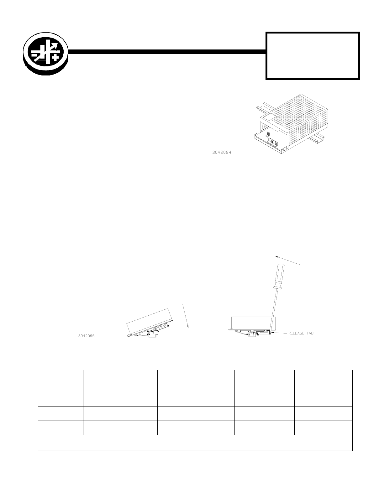
short dimension (width) as shown in Figure 1. Outline
dimensions are shown in Figure 4.
INSTALL COVER. Attach the cover to the power supply per Instruction Manual supplied with the cover.
INSTALL CLIPS. Attach left and right clips to power supply using hardware supplied (see Figure 3).
INSTALL CABLE KIT. Attach wires to the power supply per Instruction Sheet supplied with cable kit.
INSTALL POWER SUPPLY ON DIN RAIL. To mount the power supply on the rail insert one end of both clips under
one edge of the rail, then snap the other end of the two clips into place (see Figure 2A).
FIGURE 1. S SUFFIX ORIENTATION
REMOVING POWER SUPPLY FROM DIN RAIL. While grasping the power supply with one hand, use a screwdriver to
apply leverage towards the left as shown in Figure 2B to disengage each clip from the rail. Where mounting clips are
close together, it may be necessary to apply leverage with two screwdrivers simultaneously.
INSTALLATION
A -
FIGURE 2. INSTALLATION AND REMOVAL OF POWER SUPPLY FROM DIN RAIL
B -
REMOVAL
TABLE 1. COMPONENTS SUPPLIED
KIT
MODEL NO.
DIN MRW-150S CA 19 KIT 219-0184 108-0362 128-2004
DIN MRW-160S CA 20 KIT 219-0184 108-0362 128-2004
DIN MRW-170S CA 20 KIT 219-0239 108-0362 128-2004
NOTE: Clip and Bracket are supplied preassembled into left and right mounting clip assemblies. To replace a mounting clip assembly, order
both the clip and bracket and assemble per Figure 3 detail.
COVER
PART NO.
CABLE KIT
PART NO.
CLIP
(QTY 2)
PART NO.
BRACKET
(QTY 2)
PART NO.
SCREW (QTY 4)
PART NO.
101-0383
(8-32 X 0.187 PHPH)
101-0383
(8-32 X 0.187 PHPH)
101-0383
(8-32 X 0.187 PHPH)
WAS HE R (QTY 4)
PART NO.
103-0017
(NO. 8, INT. TOOTH)
103-0017
(NO. 8, INT. TOOTH)
103-0017
(NO. 8, INT. TOOTH)
KEPCO, INC. l 131-38 SANFORD AVENUE l FLUSHING, NY. 11352 U.S.A. l TEL (718) 461-7000 l FAX (718) 767-1102
http://www.kepcopower.com l email: hq@kepcopower.com
©2000, KEPCO, INC
Data subject to change without notice 228-1398 REV 1
1
Page 2
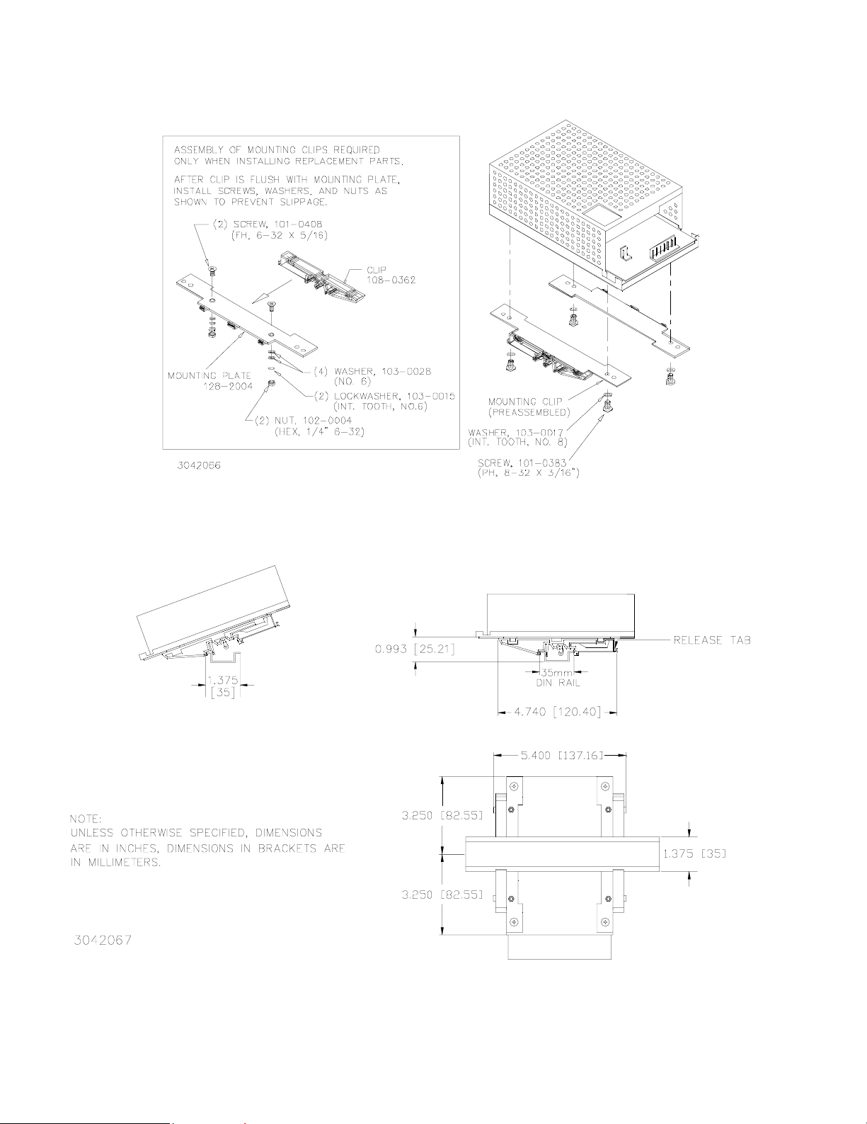
FIGURE 3. INSTALLATION OF KIT ON MRW POWER SUPPLY
FIGURE 4. MRW POWER SUPPLY WITH KIT INSTALLED, OUTLINE DIMENSIONS
KEPCO, INC. l 131-38 SANFORD AVENUE l FLUSHING, NY. 11352 U.S.A. l TEL (718) 461-7000 l
2
http://www.kepcopower.com l email: hq@kepcopower.com
228-1398 REV 1 061901
FAX (718) 767-1102
 Loading...