

Page 1
OPERATOR MANUAL
KEPCO
An ISO 9001 Company.
100 WATT SINGLE OUTPUT
SWITCHING POWER SUPPLIES
I — INTRODUCTION
SCOPE OF MANUAL. This instruction manual covers
the installation and operation of the Kepco JBW 100W
Series of RoHS (Reduction of Hazardous Substances)
compliant Switching Power Supplies.
DESCRIPTION. The Kepco JBW 100W Series consists
of four models of switching power supplies, each with a single output as shown in Table 1. Units may be operated with
a nominal 100 to 120V a-c and 220 to 240V a-c (input voltage range 85 to 265 Va-c), 50-60 Hz (input frequency
range 47-440Hz.) They will also operate on 120V to 370V
d-c input. The JBW 100W Series employs a light weight ferrite core. Regulation is provided by pulse width modulation.
Power Factor Correction (PFC) is provided by a boost converter operating at 80kHz. A FET power stage, operating
as a forward converter with a fixed switching frequency of
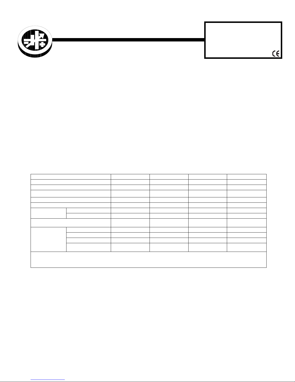
TABLE 1. OUTPUT RATINGS AND SPECIFICATIONS, JBW 100W SERIES
MODEL
OUTPUT VOLTS, d-c
ADJUSTMENT RANGE
CURRENT/MAX. POWER RATINGS
OVERCURRENT (AMPS)
OVP RANGE (VOLTS)
EFFICIENCY (typ.)
ACCEPTABLE EXTERNAL OUTPUT CAPACITOR
(1) 5.0A peak, t
(2) 0 to 100% load, 0 to 60 °C, tested with 100µF electrolytic and 0.1µF film capacitors across the measuring points, connected to the
µFmax., (fixed load resistance)
RIPPLE AND
(2)
NOISE
(mV p-p)
≤ 10 seconds, not to exceed 4.3A rms, output power ≤ 100W.
power supply via 5.9 in (150mm) wires; oscilloscope bandwidth
100 Va-c
240 Va-c
ripple (typ)
ripple (typ) (-10 to 0°C)
spike noise (typ)
spike noise (typ)
(-10 to 0
°C)
JBW 5-20K JBW 12-8.5K JBW 15-6.7K JBW 24-4.3K
5V ±0.25V 12V ±0.6V 15V ±0.75V 24V ±1.2V
4.5-5.5V 10.8-13.2V 13.5-16.5V 21.6-26.4V
20.0A/100W 8.5A/102W 6.7A/100.5W
21.0 min. 10.6 min. 8.38 min. 5.38 min
5.75-6.9 13.8-16.8 17.2-21.0 27.6-33.6
78% 80% 80% 82%
80% 82% 82% 85%
30,000 30,000 30,000 30,000
80 120 120 120
140 160 160 160
120 150 150 150
160 180 180 180
JBW
100W SERIES
150kHz provides a smooth isolated d-c output. A thermistor
circuit prevents excessive turn-on current surge. Overvoltage protection is provided. Current limiting with automatic
recovery from short circuit is featured. Units are manufactured on an open frame PC board.
Table 1 contains specifications and operating limits of individual JBW 100 Series models. Section II (following) contains specifications and operating limits common to all JBW
75W Series Models
II — SPECIFICATIONS
The following specifications are at nominal input voltages
and 25°C and apply to all models unless otherwise specified.
(1)
4.3A
/103.2W
≤ 20MHz.
INPUT CHARACTERISTICS:
INPUT VOLTAGE: (0 to 100% load, -10 to 60°C)
Nominal 100-120V a-c, 220-240V a-c
Range: 85-265V a-c, 120 -370V d-c
NOTE: The power supply may shut down if operated at
below the input voltage range or if the input voltage
increases slowly at start up (> 1 second). To reset the
power supply, unplug the unit, wait one minute and
reapply input power.
INPUT SOURCE FREQUENCY:
INPUT CURRENT: (100% load at 25°C with nominal out-
put voltage):
100V a-c input: 1.3A typ., 1.8A max.
240V a-c input: 0.6A typ., 1.0A max.
INPUT PROTECTION AND SOFT START: A thermis-
tor circuit reduces start-up surge. Units are protected
against shorts by an input fuse. Fuse value 5A, 250V.
INPUT SURGE: Cold start:
100V a-c input, 100% load: 15A typ., 30.0A max.
240V a-c input, 100% load: 30A typ., 60.0A max.
Nominal 50/60 Hz;
Range 47-66 Hz (Above 66Hz to 440 Hz the leakage
current may exceed the VDE safety specification limit.)
KEPCO, INC. 131-38 SANFORD AVENUE FLUSHING, NY. 11355 U.S.A. TEL (718) 461-7000 FAX (718) 767-1102
http://www.kepcopower.com email: hq@kepcopower.com
©2010, KEPCO, INC 1
Data subject to change without notice 228-1552 REV 2
Page 2

LEAKAGE CURRENT: Cold start:
100V a-c and 60 Hz (single pole switching) (operating
in conformance with Den-An):
0.75mA max, 0.2mA typ
240V a-c and 60 Hz (single pole switching in conformance to UL 1950/IEC 950):
0.75mA max, 0.35mA typ
POWER FACTOR:
100V a-c: 0.99 typ.
240V a-c: 0.95 typ.
OUTPUT CHARACTERISTICS:
SOURCE EFFECT: (85 to 265 Va-c)
0.4% max.
LOAD EFFECT: measured at sensing terminals
(0% - 100% load change)
0.8% max.
TEMPERATURE EFFECT: (-10 to 60°C)
1.0% max.
COMBINED EFFECT:
2.0% max. (4% typical for overshoot at start-up)
TIME EFFECT OR DRIFT: (1/2 to 8 hr. at 25°C)
0.4% max.
TRANSIENT RECOVERY: A step load change from
50% to 100% of rated load in 50 microseconds or more
produces no more than 4% output voltage excursion.
Temperature range from -10 to 60°C. Recovery time is
1mS maximum.
HOLD UP TIME: Condition: 100% output load. Upon
input interruption the output is maintained for:
100 Va-c: 40mS typ.
240 Va-c: 40mS typ.
START UP TIME:
100 Va-c: 500mS max., 400mS typ.
240 Va-c: 500mS max., 300mS typ.
OVERVOLTAGE PROTECTION: Fixed, factory set.
See Table 1. Latching will occur.
OVERCURRENT: Square type, output voltage returns
to rated level upon removal of cause of malfunction (long
term overcurrent could damage unit).
ENVIRONMENTAL CHARACTERISTICS
OPERATING TEMPERATURE: -10 to 60°C (start up
-20 to -10°C). See the derating, Figure 1.
STORAGE TEMPERATURE: -30°C to + 75°C.
COOLING: Natural convection. Do not allow the power
supply to become dust covered because that will
decrease the cooling efficiency of the unit and cause insulation to deteriorate.
HUMIDITY: 10% to 90% relative humidity, operating
and storage, noncondensing, wet bulb temperature < or =
35°C.
VIBRATION: Three axes, one hour each, sweep time
10 min., nonoperating.
5-10 Hz., 10 mm amplitude
10-200 Hz., 2G (19.6m/s
SHOCK: Three axes, 60G (588m/s
2
) acceleration
2
), 11 mS ±5mSec
pulse duration, three shocks each axis, nonoperating, 1/2
sine pulse.
GENERAL CHARACTERISTICS
WITHSTANDING VOLTAGE: (at 5 to 35°C ambient,
45 to 85% relative humidity, cutout current 10 mA):
Between input and output terminals:
3.0 KV a-c for 1 minute.
Between input terminals and ground:
2000V a-c for 1 minute.
Between output terminals and ground:
500V a-c for 1 minute.
INSULATION RESISTANCE: Between input and output, input and ground, output and ground: 100 megohms
minimum (500V d-c, 5 to 35°C ambient, 45 to 85% relative
humidity)
SAFETY: All units designed to meet UL 60950-1.c, and
TÜV Rheinland EN60950-1 (ambient temp. 50°C max.).
JBW 100W units are CE marked per the Low Voltage
Directive (LVD), EN60950.
EMC - EMISSIONS:
• Conducted Noise: 0.15MHz to 30MHz:
FCC Class B, VCCI-B, EN55011-B, EN55022-B.
• Input Harmonics (on AC Mains) 0 to 2KHZ:
EN 61000-3-2.
EMC - IMMUNITY: Designed to meet EN 61000-6-2.
• ESD:
EN 61000-4-2 Level 4, Normal operation.
• Radiated Field Noise:
EN 61000-4-3 Level 3, Normal operation.
• Electrical Fast Transient/Burst (EFT):
EN 61000-4-4 Level 3, Normal operation.
• Surge:
EN 61000-4-5 Level 4, no damage.
• Conducted Noise:
EN 61000-4-6 Level 3, Normal operation.
• Power Frequency Magnetic Field:
EN 61000-4-8 Level 4, Normal operation.
• Interruptions and voltage dips, short variations:
EN 61000-4-11, Normal operation.
WARRANTY: One year.
ORIENTATION: Vertical or horizontal (see Figure 2).
KEPCO, INC. 131-38 SANFORD AVENUE FLUSHING, NY. 11355 U.S.A. TEL (718) 461-7000 FAX (718) 767-1102
http://www.kepcopower.com email: hq@kepcopower.com
2 228-1552 REV 2 061510
Page 3
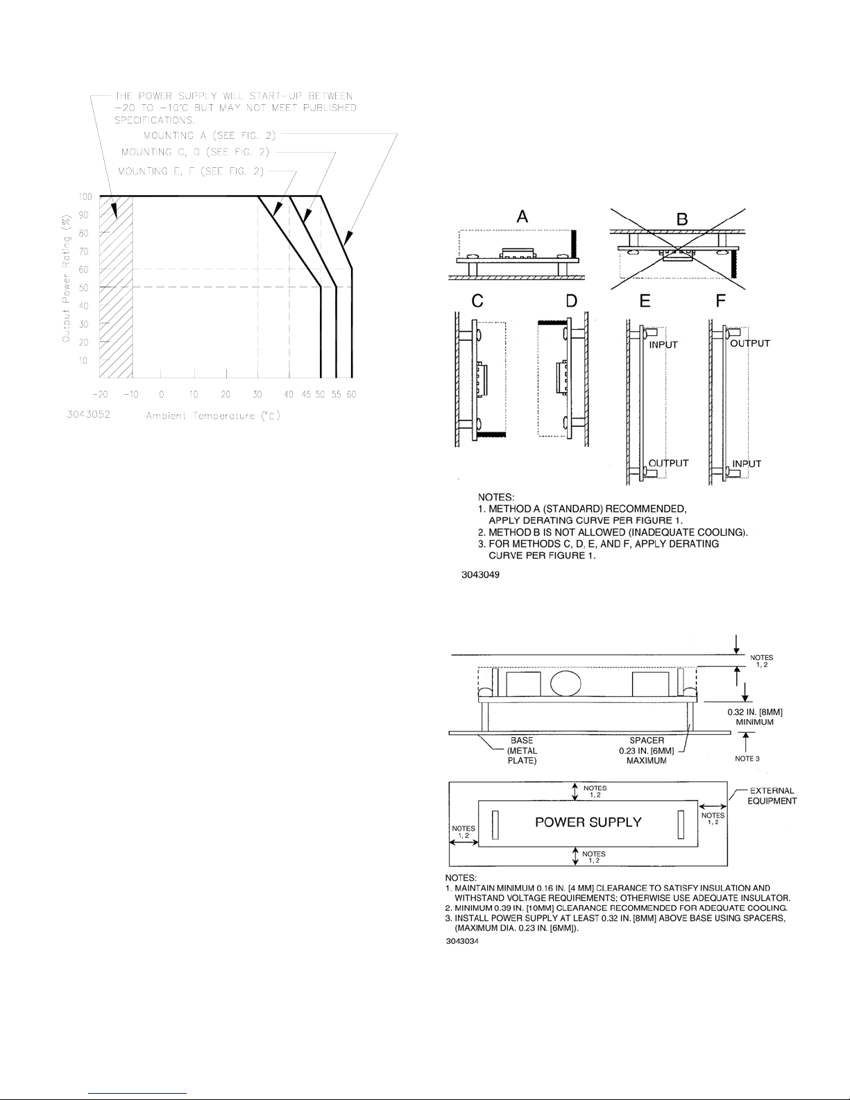
FIGURE 1. OUTPUT POWER VS. TEMPERATURE
III — INSTALLATION
IV — OPERATION
PROTECTION DIODE: When a number of power sup-
plies are operating in series, the current rating is to be limited to the rating of the power supply with the lowest rating.
A diode (Vr>2 Vo, If>2Io, Vf<< low) must be connected to
the power supply output terminals to protect the unit from
reverse voltage.
Σ
MOUNTING POWER SUPPLY. Refer to Figures 2, 3
and 4. The unit may be mounted on one mounting surface.
The temperature of the air surrounding the power supply
must not exceed the ambient values given in the graph in
Figure 1.
INSULATION. Install unit at least 0.3 inches (8mm)
away from base with 0.24 inch (6mm) diameter spacers
attached to the PC board. Keep at least 0.16 inches (4mm)
spacing around and above the unit to comply with insulation and safety requirements. An insulator must be used if
the spacing is less than 0.16 inches (4mm) (see Figure 3).
VENTILATION.
It is recommended to keep at least 0.40
inches (10mm) clearance from adjacent equipment for
proper ventilation (see Figure 3).
CONNECTIONS.
Connect a load to the output of the
power supply by connecting pins 5 through 8 (+) of output
connector CP2 to the load (+) terminal, and pins 1 through
4 (–) to the load (–) terminal. See Figure 4 for input/output
connector and pin locations.
When connecting the power supply to the load, keep the
wires as short as possible, and use twisted pairs (use Wire
Size AWG No. 22). Make sure there is only a single ground
point in the load circuit. Capacitors (100UF electrolytic and
0.1UF film) can be placed across the load to filter out
noise.The AC input power is applied via input connector
CP1. Make sure to connect the AC input Neutral and Line
wires to pins 3 and 1, respectively, of CON1. See Figure 5
for mating connector information. A Cable Kit (P/N 219-
0495) is available as an option from Kepco. The kit
includes one input and one output cable (one meter long)
with the mating connectors for Input and Output connectors
at one end and unterminated wires at the other end.
FIGURE 2. MOUNTING DIRECTION
.
FIGURE 3. VENTILATION AND INSULATION
REQUIREMENTS
KEPCO, INC. 131-38 SANFORD AVENUE FLUSHING, NY. 11355 U.S.A. TEL (718) 461-7000 FAX (718) 767-1102
061510 228-1552 REV 2 3
http://www.kepcopower.com email: hq@kepcopower.com
Page 4
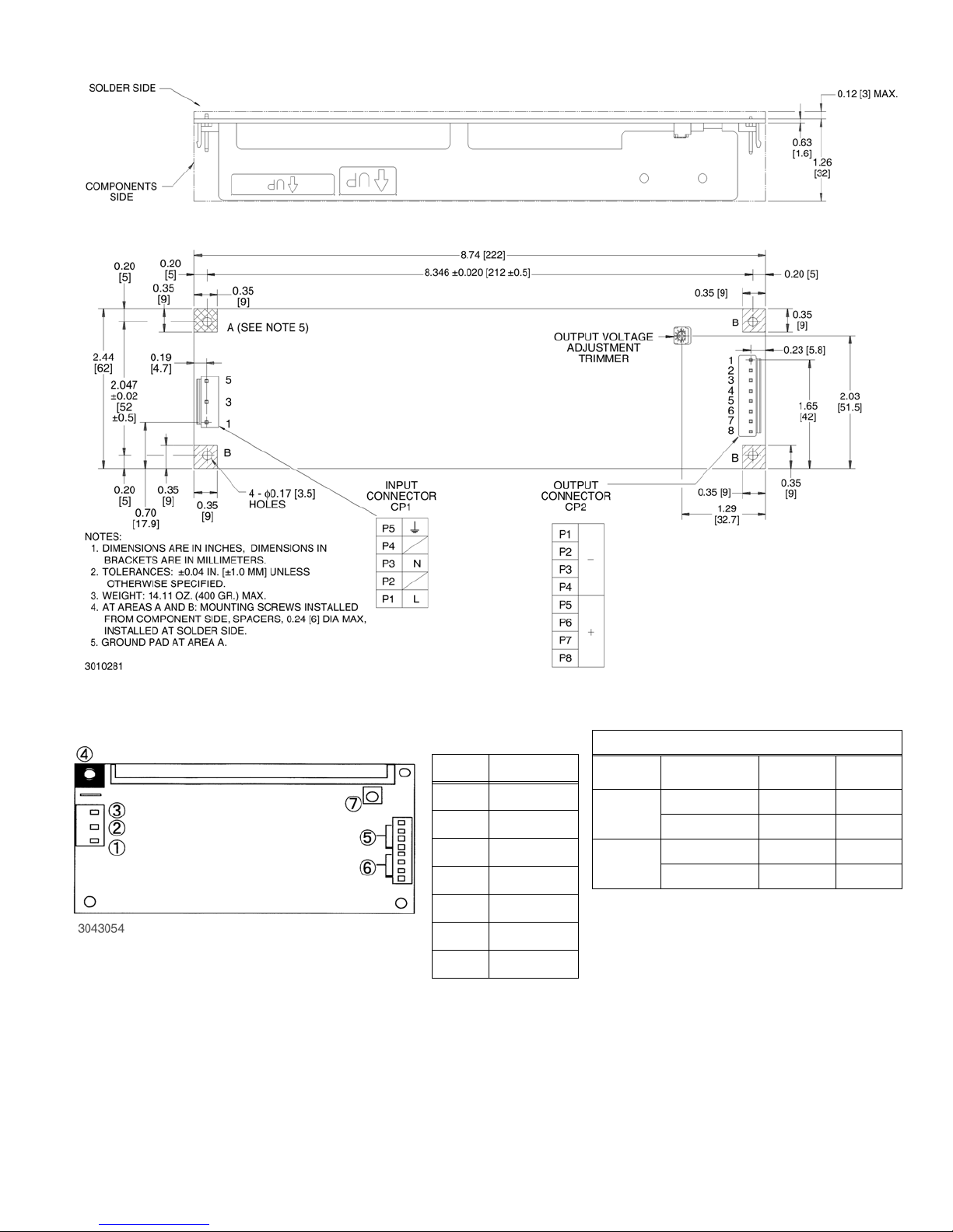
FIGURE 4. JBW 100W MECHANICAL OUTLINE DIAGRAM
INPUT
OUTPUT
Item Function
1 Input L
2 Input N
3Ground
4 Ground Pad
5 Output (-)
6Output (+)
7 Vadj control
Mating Connectors
Connector Terminal Pin
Input
Output
SVH-21T-P1.1 VHR-5N
T101 H101-05
SVH-21T-P1.1 VHR-8N
T101
(1) JST= Japan Solderless Terminal Mfg. Co.
(2) LCE= Long Chu Electronics Co.
(3) Optional cable kit (P/N 219-0495) includes
one input and one output cable (one meter
(3)
Socket
Housing
H101-08
long) with mating connectors for Input and
Output connector, unterminated at other end.
FIGURE 5. INPUT/OUTPUT CONNECTIONS
KEPCO, INC. 131-38 SANFORD AVENUE FLUSHING, NY. 11355 U.S.A. TEL (718) 461-7000 FAX (718) 767-1102
http://www.kepcopower.com email: hq@kepcopower.com
4 228-1552 REV 2 061510
MFR
JST
LCE
JST
LCE
(1)
(2)
(1)
(2)
 Loading...