

Page 1

INSTRUCTION MANUAL
KEPCO
An ISO 9001 Company.
KEPCO SINGLE OUTPUT 100 WATT
HOT SWAP PLUG-IN POWER SUPPLIES
I — INTRODUCTION
The Kepco HSF-PFC 100 Watt series hot swappable, high
frequency switching, plug-in power supplies with built in
power factor correction employ forward conversion and are
designed to operate in a fault tolerant power system with
either a-c or d-c input. A negative temperature coefficient
(NTC) thermistor limits start-up surge. A built-in forced current share circuit and OR-ing diodes allow configuration for
hot-swap and parallel-redundant N+1 operation.
These power supplies are designed to be installed in
Kepco’s RA 19-(X)B Rack Adapters (Figure 2). RA 19-6B
accepts up to six 150W units, RA 19-7B accepts up to three
150W units, and up to four 50W or 100W units and RA 198B accepts up to eight 50W or 100W units. The applicable
RA 19-(X)B Operator Manual can be downloaded from the
Kepco web site at:
www.kepcopower.com/support/opmanls.htm#ra19-xb
All input/output connections are through a 24 pin connector
that plugs in to the rack adapter. All external connections
are made through the rack adapter.
HSF-PFC
100W SERIES
Seven models may be selected for outputs of 3.3, 5, 12, 15,
24, 28, or 48V (see Table 1 or 2).
When the input is cut off, the output is maintained for 20
milliseconds minimum. If the power supply shuts down due
to an output overvoltage condition, it is then necessary to
turn the unit off and wait approximately 30 seconds minimum before turning the unit on again.
Specifications for each model of the HSF-PFC 100 Watt
Series are listed in Section III, on page 4 (standard models)
and Section IV, on page 6 (suffix C, T, X and Y).
OPTIONS. Options are identified by suffix: T (-PFCT) offers improved efficiency and less weight; C (-PFCC) offers current monitoring via an integral current sensing resistor (includes option T); X (-PFCX) offers remote on/off (includes option T); and Y (-PFCY) includes options C, X and T.
II — FEATURES
FRONT PANEL ACCESS. The front panel provides a
power ON/OFF switch controlling input power and a “VDC
ON” light which indicates when the unit is operating. NOTE:
The ON/OFF switch must be set to OFF before removing unit from (or inserting into) rack adapter.
The front panel “MASTER ON” LED lights when 1) the unit
operates independently, or 2) the unit is used in parallel
redundant configurations while a) the output current is
within 10% to 100% of nominal and the unit is functioning
as a master or b) the output current is less than 10% of
nominal. In parallel redundant configurations, the module
with the highest voltage functions as the master. The other
units are slaves, and track the output voltage of the master.
Refer to Current Share Bus (CSB) on page 3 for details.
(The MASTER ON LED is not used on 3.3V model; it is
always off.)
KEPCO, INC. 131-38 SANFORD AVENUE FLUSHING, NY. 11355 U.S.A. TEL (718) 461-7000 FAX (718) 767-1102
http://www.kepcopower.com email: hq@kepcopower.com
©2013, KEPCO, INC 1
Data subject to change without notice 228-1533 REV 15
The front panel Vadj trimmer provides adjustment of the
output voltage within the limits specified in Table 1 or 2; test
points connected to the +S and –S lines are available at the
front panel for measuring the output voltage.
FORCED CURRENT SHARE CIRCUIT. (Not available on 3.3V model.) When units are configured for N+1 parallel redundant operation, it is desirable for current to be divided equally among the paralleled supplies. When the CSB (Current Share Bus) lines of paralleled units are connected together, the load current is forced to divide equally between all paralleled units. If one unit fails, the remaining units continue to supply the load, and the load current is divided equally among the remaining operating units. The failed unit is automatically isolated from the circuit by a built-in isolation diode. Refer to Current Share Bus (CSB) on page 3 for details.
Page 2
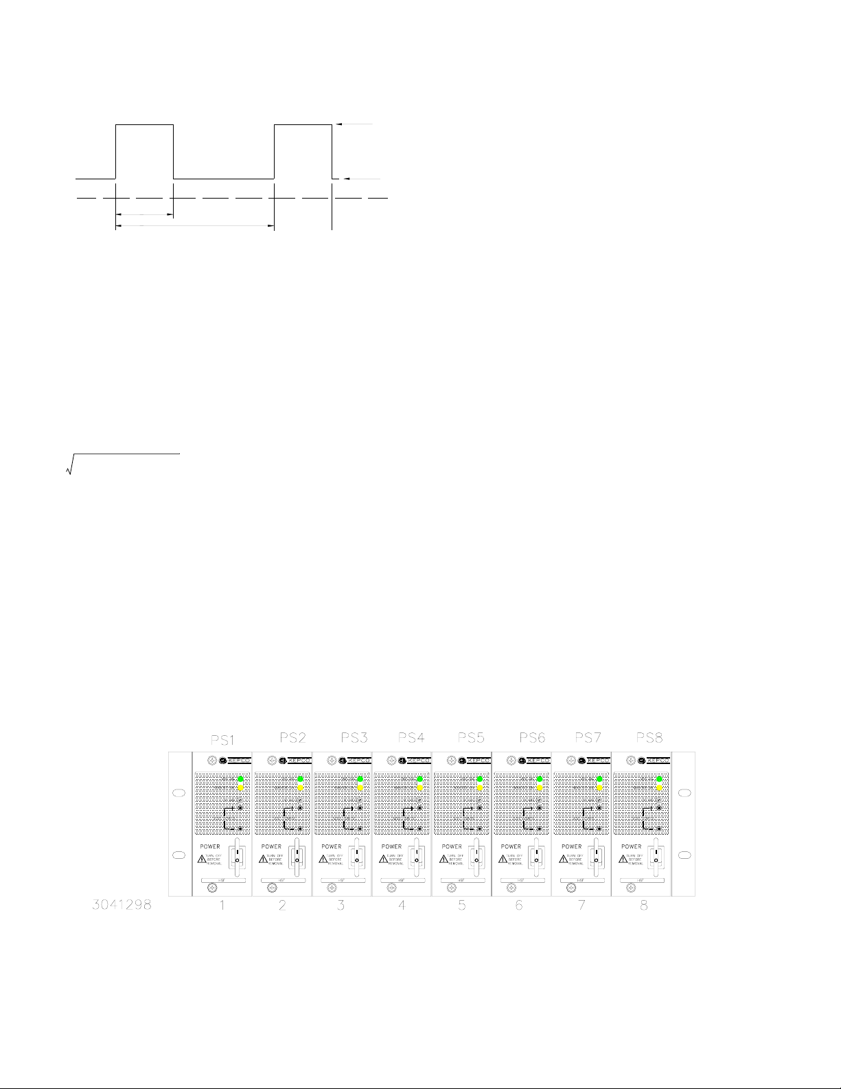
I
1
I
2
t
3043527
T
D=(t/T)
The standard 24V Model (no options) can supply Peak
current listed in Table 1 if the four conditions listed below
are met. These models include thermal protection, voltage shutdown type. Restart by removing a-c input; after
sufficient cooling, reapply a-c input (wait at least 30 seconds).
1. Time: t ≤ 10 Seconds
2. I
≤ Peak Current (Amperes)
1
3. Effective Current:
2
≤ Rated current (Amperes)
DI
1
ID–()I
2
×+
2
4. Effective Power P ≤ Maximum Power (Watts)
(output RMS current x output voltage)
FIGURE 1. 24V MODEL PEAK CURRENT REQUIREMENTS (
REMOTE ON-OFF. Remote on-off (X and Y models only) is via ±RC assigned to pins of the RA 19-(X)B I/O connector: off = no voltage, short circuit, or 0 to 0.8V, on =
4.5 to 12.5V (or 12.5 to 24.5V via 1.5K Ohms). To reverse
on-off polarity contact Kepco. There is no isolation
between ±RC, d-c output and alarm circuit. Refer to the
applicable RA 19-(X)B Manual for details.
CURRENT MONITOR. Current monitor (C and Y models only) is via ±IMON assigned to pins of the RA 19(X)B I/O connector. Monitored Output Current (Amps) = Voltage drop across R R
is the sum of RS (see Table 2) + trace resistance to
EQ
(mVolts) / REQ (mOhms) where
EQ
point where current monitor is connected, approximately
4mOhms. The voltage drop across R
is measured
EQ
across ± IMON pins (requires millivoltmeter, range 0 to
250mV). Accuracy is ±10%; contact Kepco if greater
accuracy is required. There is no isolation between
±IMON, alarm circuit and d-c output. Refer to the applicable RA 19-(X)B Manual for details.
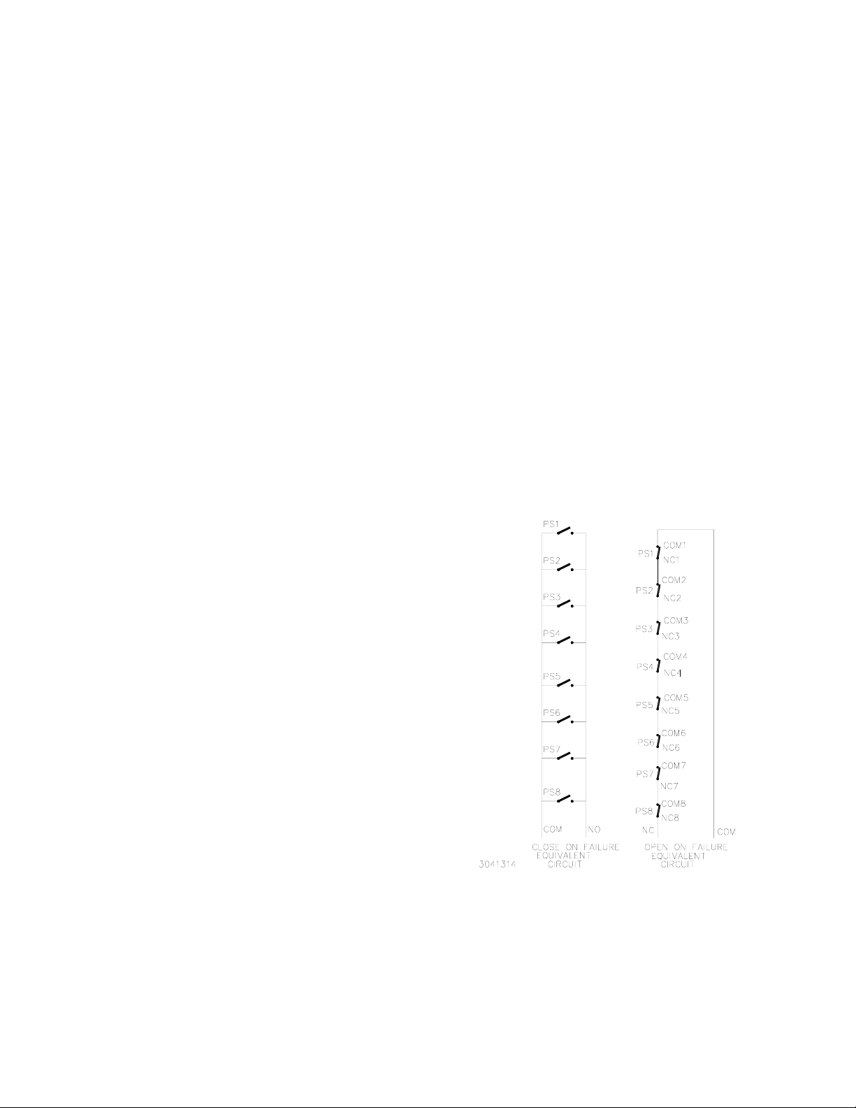
ALARM CIRCUIT. Any condition which causes the unit to be out of specified voltage/current ranges (including overvoltage, overcurrent, overtemperature, open sense line, ac input line failure, etc.) results in an alarm. All models include an isolated internal relay offering normally closed and normally open contacts referenced to an isolated common. These contacts are rated for 1A at 30V d-c and 0.5A at 125V a-c. These contacts may be used to configure “close on failure” or “open on failure” alarm circuits (see Figure 3 for typical alarm circuits). Refer to the applicable RA 19-(X)B Manual for details about the following: 1) normally open (close on failure) contacts are not available if ±RC is used on X and Y suffix models, 2) alarm signals are not isolated on C, X and Y models and
3) alarm configurations for multiple power supplies.
KEYING. Keying of the power supply is established at the factory. The output voltage determines which keyway is open. When the corresponding rack adapter key (pin) is installed by the user, only a power supply of the correct voltage can be inserted in the rack adapter slot.
FIGURE 2. HSF-PFC 100 WATT POWER SUPPLIES (8) INSTALLED IN RA 19-8B RACK ADAPTER
KEPCO, INC. 131-38 SANFORD AVENUE FLUSHING, NY. 11355 U.S.A. TEL (718) 461-7000 FAX (718) 767-1102
http://www.kepcopower.com email: hq@kepcopower.com
2 228-1533 REV 15 083013
Page 3
CONNECTIONS: The 24-pin I/O connector is designed to mate with the corresponding connector in the Series RA 19-(X)B Rack Adapter. (See Rack Adapter manual for pin assignments.)
(+) SENSE, (–) SENSE: These lines are provided to compen-
sate for voltage drops in the load connecting wires. The
Sense lines must be connected to their respective (+)
and (–) output terminals, either at the load or at the rack
adapter (see Rack Adapter Manual). The connection
ensures the most accurate error tracking. Maximum voltage drop compensation in the load connecting wires for
each model is calculated as the difference between the
minimum overvoltage (see Table 1 or 2) and the maximum
adjustment range (see Table 1 or 2), divided by two to give
the voltage drop compensation per lead. Higher compensation values are possible if output voltage is decreased
below the maximum adjustment range shown in Table 1 or
2.
NOTE:
The Sense lines must be connected for
the power supply to work properly!
OUTPUT (+), OUTPUT (–): These lines are the power supply
d-c output lines which are connected to the load.
to parallel many units and still keep all units within 250 mV
of each other. Adjust the outputs using Vadj trimmer on
front panel.
• Optimum difference among output voltages of paralleled units: 40mV
• Maximum difference among output voltages of
paralleled units: 250 mV
• Minimum difference among output voltages of paralleled units: 25 mV
ALARM: The Alarm NC (normally closed) - Open on Fail-
ure and Alarm NO (normally open) - Close on Failure lines
are relay contacts referenced to Alarm Common. If the unit
fails, the path between Alarm NC - Open on Failure and
Alarm Common opens, the path between Alarm NO - Close
on Fail and Alarm Common is a short circuit. Figure 3 illustrates typical Close on Fail and Open on Fail circuits to give
a failure indication if any one of a number of power supplies
fail. See RA 19-(X)B Manual for limitations applicable to C,
X and Y suffix models described in “Alarm Circuit.” on
page 2.
INPUT POWER: Line (either a-c or d-c source power), Neu-
tral and Ground (chassis)
CURRENT SHARE BUS (CSB): (Not available on 3.3V
model.) Connecting the CSB lines of power supplies operating in a parallel configuration causes output current to be
shared equally. (See Rack Adapter Manual for additional
information on parallel configurations.). For current sharing
to work properly the outputs of all paralleled units must be
within 250 mV (max) of each other and each unit must be
operating at between 10% to 100% of rated output current.
If current to the load goes below 10% for each unit in current share mode, all MASTER ON lights may go on (see
load effect specifications); this indicates that forced current
share is no longer working, units are simply in automatic
current share mode. (If forced current sharing at less than
10% nominal current per supply is needed, contact Kepco
application engineering.) Remote sensing is recommended. For master/slave operation to work properly each
unit should be adjusted to 40 mV (optimum) less than the
next paralleled unit. Unit 1 is adjusted to V
– 40mV, and unit 3 to V
V
OUT
– 80mV, etc. If the master
OUT
, unit 2 to
OUT
fails, the unit 2 will become the new master. The 40 mV difference can be reduced to a minimum of 25 mV as needed
FIGURE 3. TYPICAL ALARM CIRCUIT DIAGRAMS
KEPCO, INC. 131-38 SANFORD AVENUE FLUSHING, NY. 11355 U.S.A. TEL (718) 461-7000 FAX (718) 767-1102
083013 228-1533 REV 15 3
http://www.kepcopower.com email: hq@kepcopower.com
Page 4

III — SPECIFICATIONS (STANDARD)
The following specifications apply to all standard (no suffix) HSF-PFC 100 Watt Series models. Table 1 lists the
specifications that differ for each model. Common specifications that apply to all standard models are listed in the
paragraphs following Table 1. Other models are also avail-
TABLE 1. OUTPUT RATINGS AND SPECIFICATIONS, HSF-PFC 100W SERIES (STANDARD: NO SUFFIX)
able; consult your Kepco representative for their specifications.
NOTE: Common specifications apply to all models except
where otherwise indicated.
MODEL
OUTPUT VOLTS, d-c (NOMINAL) 3.3V 5V 12V 15V 24V 28V 48V
ADJUSTMENT RANGE 2.8 - 3.4V 4.3 - 5.3V 11.4 - 12.6V 13.5 - 16.5V 19.2 - 26.0V 26.5 - 29.5V 44.0 - 52.0
OVERVOLTAGE SETTING
(25 °C, NOM. INPUT)
OUTPUT CURRENT (NOMINAL)
CURRENT LIMIT
OUTPUT POWER (MAX.)
EFFICIENCY (typ.)
RIPPLE AND NOISE
(mV p-p)
0-40°C, 10-100%
LOAD
(1) Derates same as Output Power.
(2) Current Limit is rectangular. After the overload is removed,
output is automatically restored.
(3) See power derating curve, Figure 4.
(5)
switching (max) 80 80 100 100 100 100 130
spike noise (max)
(d-c—50MHz)
(1)
(2)
(3)
100 Va-c 74% 77% 80% 80% 81% 81% 83%
240 Va-c 77% 82% 84% 84% 85% 85% 86%
HSF
3.3-20PFC
3.4 - 4.6V 5.2 - 6.0V 13.2 - 15.2V 16.5 - 18.5V 26.5 - 30.0V 31.5 - 34.5 53.0 - 59.5
20A 20A 8.5A 7.0A
26.2A min 21.0A min 8.92A min 7.35A min 6.82A min 3.99A min 2.2A min
68W 100W 99.6W 99W 100.8W 98W 96W
<120 <120 <150 <150 <150 <150 <200
INPUT:
Voltage:
Nominal:120V a-c/240V a-c;
Range:
90-264V a-c;
125-370V d-c. (polarity insensitive)
Frequency: Nominal: 50-60 Hz; Range: 47-440Hz
(From 66 to 440 Hz leakage current may exceed
UL/VDE safety spec. limit.)
Current (nominal output at rated load):
1.4A a-c max
@120V a-c rms
1.2A max for 3.3V model
0.7A a-c max
@240V a-c rms
0.6A max for 3.3V model
Initial Turn-on Surge: cold start 25°C (First surge
only, not including the current flow into the EMI filter):
14A typ. @ 100 V a-c, 100% load
28A typ. @ 200 Va-c, 100% load
Power Factor: 0.99 typ. @100V a-c;
0.95 typ. @ 200V a-c.
Switching Frequency:
135KHz typical
HSF
5-20PFC
HSF
12-8.5PFC
(4) Peak current and thermal protection; applicable to 24V model only.
See Figure 1 for peak power requirements.
(5) Ripple and noise will be approximately 1.5 times higher when
operating temperature range is between –10°C to 0°C.
HSF
15-7PFC
HSF
24-4.5PFC
4.5A
(6.5A Peak)
(4)
HSF
28-3.8PFC
3.8A 2.1A
STABILIZATION:
Source Effect (full load): 0.2% typ.; 0.3% max.
Range 90-132V a-c, 170 -264V a-c,
Load Effect (10% to 100% load change):
0.5% typ.; 1.5% max.
Temperature Effect: Range –10
o
to 71oC
0.5% typ.; 1.0% max.
Combined Effect (includes source, load, and
temperature effects):
0.9% typ.; 1.8% max.
Time Effect (1/2 hr-8 hr at 25
o
C):
0.2% typ.; 0.5% max.
RECOVERY CHARACTERISTICS: A step load change from 50% to 100% produces less than + excursion. Recovery occurs to within + setting in <1 ms (load change t
r
1% of the original
or tf equal to or greater
than 50µsec).
START-UP TIME:
500 ms. maximum @100V a-c
300 ms. typical @100V a-c
200 ms. maximum @240V a-c
100 ms. typical @240V a-c
HSF
48-2.1PFC
4% output
KEPCO, INC. 131-38 SANFORD AVENUE FLUSHING, NY. 11355 U.S.A. TEL (718) 461-7000 FAX (718) 767-1102
http://www.kepcopower.com email: hq@kepcopower.com
4 228-1533 REV 15 083013
Page 5

III — SPECIFICATIONS (STANDARD) - CONTINUED
HOLDUP TIME:
37 ms. typ., 20 ms. min. (100V a-c)
45 ms. typ., 25 ms. min. (240V a-c)
DIELECTRIC STRENGTH:
Between input and output:
2KV a-c for one minute.
Between input and case (ground):
2KV a-c for one minute.
Between output and case (ground):
[500V a-c for one minute.]
INSULATION RESISTANCE: Between input and ground, output and ground, input and output:
100 Megohms min. (500V d-c).
OPERATING TEMPERATURE: See Figure 4.
Standard models
(no suffix)
Options
C, T, X and Y
LEAKAGE CURRENT
0.23mA typical, 0.35 mA maximum
(per IEC 950 and UL1950,120V a-c)
0.45mA typical, 0.70 mA maximum
(per IEC 950 and UL1950, 240V a-c)
SAFETY: Units are designed to meet UL60950 3rd Edition, CSA 22.2 No. 60950 [60950-1], and EN60950 and are CE marked per the Low Voltage Directive (LVD), 73/23/ EEC and 93/68/EEC. The standards do not apply with DC input operation.
EMI: Designed to meet FCC Class B (100-120V a-c) and VDE 0871 Class B (220-240V a-c).
VIBRATION: (non-operating, one hour on each one of the three axes):
5-10 Hz, 10 mm amplitude.
10-55 Hz, 2g acceleration.
SHOCK: (non-operating, one-half sinusoidal pulse, three shocks to each axis):
Acceleration: 60g
Duration: 11ms +
5ms
FIGURE 4. % OUTPUT POWER RATING VS.
AMBIENT TEMPERATURE
STORAGE TEMPERATURE: -30oC to +75oC.
RELATIVE HUMIDITY: Operating and storage: up to
95% (wet bulb temp. <35
o
C non-condensing).
FUSE: Slow Blow, 3.15A, 250V; (5 x 20 mm),
Littelfuse, P/N 2153.15PF;
Kepco P/N 541-0135.
DIMENSIONS: See Figure 6.
WARRANTY: 5 years.
KEPCO, INC. 131-38 SANFORD AVENUE FLUSHING, NY. 11355 U.S.A. TEL (718) 461-7000 FAX (718) 767-1102
083013 228-1533 REV 15 5
http://www.kepcopower.com email: hq@kepcopower.com
Page 6

IV — SPECIFICATIONS (C, T, X, Y)
The following specifications apply to all HSF-PFCC,
PFCT, PFCX, and PFCY (suffix C, T, X, Y) 100 Watt
Series models. Table 2 lists the specifications that differ
for each model. Common specifications that apply to all
TABLE 2. OUTPUT RATINGS AND SPECIFICATIONS, HSF-PFC 100W SERIES (SUFFIX C, T, X, Y ONLY)
suffix C, T, X, Y models are listed in the paragraphs following Table 2.
NOTE: Specifications apply to all models except where
otherwise indicated.
HSF 3.3-25
MODEL
OUTPUT VOLTS, d-c (NOMINAL) 3.3V 5V 12V 15V 24V 28V 48V
ADJUSTMENT RANGE 2.8 - 3.5V 4.3 - 5.3V 11.4 - 12.6V 13.5 - 16.5V 19.2 - 26.0V 26.5 - 29.5V 44.0 - 52.0V
OVERVOLTAGE SETTING
(25°C, Nom. Input)
OUTPUT CURRENT (NOMINAL)
CURRENT LIMIT SETTING
w(25°C, Nom. Input)
Rectangular type characteristic
OUTPUT POWER (MAXIMUM)
EFFICIENCY (typ.)
RIPPLE AND
(5)
NOISE
(mV p-p)
0-40°C,
10-100% load
Sense Resistor Value (milliohms)
(1) Unless otherwise noted, specifications are identical for all options.
(2) Forced current Share not available for 3.3V Models.
(3) Derates same as Output Power.
(4) See power rating curve, Figure 3.
spike noise
(d-c—50MHz)
(3)
(4)
100 Va-c 79% 83% 84% 85% 85% 85% 86%
240 Va-c 81% 85% 86% 87% 87% 87% 88%
switching
(max)
(max)
(6)
(1) (2) (7)
PFCC
PFCT
PFCX
PFCY
3.75 - 4.7V 5.6 - 6.4V 13.3 - 15.4V 16.8 - 18.8V 26.5 - 30.0V 29.7 - 34.7V 54.5 - 59.5V
(3)
25A
26.2A min. 21.0A min. 8.82A min. 7.03A min. 4.68A min. 3.8A min. 2.2A min.
82.5W 100W 100.8W 100.5W 100.8W 100.8W 100.8W
80 80 100 100 150 150 200
120 120 150 150 200 200 300
5 5 10 20 20 30 50
(1)
HSF 5-20
PFCC
PFCT
PFCX
PFCY
20A 8.4A 6.7A 4.2A 3.5A 2A
HSF12-8.4
PFCC
PFCT
PFCX
PFCY
(1)
HSF 15-6.7
(5) Ripple and noise will be approximately 1.5 times higher when
(6) Sense resistor on C and Y Models used for current monitoring. See
(7) Natural convection cooled; see Figure 4.
(1)
PFCC
PFCT
PFCX
PFCY
operating temperature range is between –10°C to 0°C.
“Current Monitor.” on page 2 for details.
HSF 24-4.2
PFCC
PFCT
PFCX
PFCY
(1)
HSF 28-3.5
PFCC
PFCT
PFCX
PFCY
(1)
HSF 48-2
PFCC
PFCT
PFCX
PFCY
(1)
INPUT:
Voltage:
Nominal:120V a-c/240V a-c;
Range:
90-264V a-c;
125-370V d-c. (polarity insensitive)
Frequency: Nominal 50-60 Hz; Range 47-440Hz
(From 66 to 440Hz leakage current may exceed
UL/VDE safety spec. limit)
Current (nominal output at rated load):
1.5A a-c max
@100-120V a-c rms
1.1A max for 3.3V model
0.75A a-c max @200-240V a-c rms
0.55A max for 3.3V model
Initial Turn-on Surge: cold start 25 °C (First surge
only, not including the current flow into the EMI filter):
14A typ. (100 V a-c, 100% load)
28A typ. (200 Va-c, 100% load)
Power Factor: 0.99 typ. @100V a-c;
0.92 typ. @ 200V a-c.
Switching Frequency:
160KHz typical
STABILIZATION:
Source Effect (full load):
Range 90-132V a-c or 170 -264V a-c,
0.1% typ.; 0.2% max.
3.3V model: 5mV typ., 10mV max.
Load Effect (10% to 100% load change):
0.5% typ.; 1.5% max.
3.3V, 5V models: 1.5% typ., 2.0% max.
Temperature Effect: Range -10° to 71°C
0.5% typ.; 1.0% max.
Combined Effect (includes source, load, and
temperature effects):
0.9% typ.; 1.8% max.
Time Effect (1/2 hr-8 hr at 25
o
C):
0.2% typ.; 0.5% max.
KEPCO, INC. 131-38 SANFORD AVENUE FLUSHING, NY. 11355 U.S.A. TEL (718) 461-7000 FAX (718) 767-1102
http://www.kepcopower.com email: hq@kepcopower.com
6 228-1533 REV 15 083013
Page 7

IV — SPECIFICATIONS (C, T, X, Y) - CONTINUED
RECOVERY CHARACTERISTICS: A step load
change from 50% to 100% produces less than +
excursion. Recovery occurs to within +
setting in <1 ms (load change t
r
1% of the original
or tf equal to or greater
4% output
than 50µsec). (3.3V: 200mV max.)
EEC and 93/68/EEC. The standards do not apply with DC
input operation.
EMI: Designed to meet FCC Class B (100-120V a-c) and VCCI, EN55011-B, EN55022-B.
START-UP TIME: 500 ms. maximum @100V a-c
400 ms. typical @100V a-c
300 ms. maximum @240V a-c
200 ms. typical @240V a-c
HOLDUP TIME:
37 ms. typ., 20 ms. min. (100V a-c)
30 ms. typ., 20 ms. min. (240V a-c)
DIELECTRIC STRENGTH:
Between input and output:
2KV a-c for one minute.
Between input and case (ground):
2KV a-c for one minute.
Between output and case (ground):
500V a-c for one minute.
INSULATION RESISTANCE: Between input and ground, output and ground, input and output:
100 Megohms min. (500V d-c).
LEAKAGE CURRENT (per IEC 950 and UL 1950)
0.13mA typ. 0.19 mA maximum, (120V a-c)
0.45 mA maximum (240V a-c)
SAFETY: Units are designed to meet UL60950 3rd Edition, CSA 22.2 No. 60950-1, and EN60950:2001 and are CE marked per the Low Voltage Directive (LVD), 73/23/
VIBRATION: (non-operating, one hour on each one of the three axes):
5-10 Hz, 10 mm amplitude.
10-55 Hz, 2g acceleration.
SHOCK: (non-operating, one-half sinusoidal pulse, three shocks to each axis):
Acceleration: 60g
Duration: 11ms +
5ms
OPERATING TEMPERATURE: See Figure 4.
STORAGE TEMPERATURE: -30
o
C to +75oC.
RELATIVE HUMIDITY: Operating and storage: up to
95% (wet bulb temp. <35
o
C non-condensing).
FUSE: Slow Blow, 3.15A, 250V; (5 x 20 mm),
Littelfuse, P/N 2153.15PF;
Kepco P/N 541-0135.
DIMENSIONS: See Figure 6.
WARRANTY: 5 years.
KEPCO, INC. 131-38 SANFORD AVENUE FLUSHING, NY. 11355 U.S.A. TEL (718) 461-7000 FAX (718) 767-1102
083013 228-1533 REV 15 7
http://www.kepcopower.com email: hq@kepcopower.com
Page 8

V — INSTALLATION
MOUNTING THE POWER SUPPLY. Refer to Figure
2 and insert power supply into selected slot of RA 19-(X)B
Rack adapter until power supply front panel is flush with
rack adapter chassis and secure with front panel Phillips
head mounting screw.
CONNECTIONS. All connections are made at the rear panel of the RA 19-(X)B Rack Adapter (see applicable RA 19-(X)B Operator Manual). Connect the load to the applicable ± DC OUTPUT terminals. AC input power to each
VI — OPERATION
Turn the unit on using the front panel POWER switch (see
Figure 5). CAUTION: DO NOT repeatedly toggle the
POWER on/off switch as this may cause unit to fault.
When output voltage is available, the green VDC ON LED
is on. While monitoring output voltage at the front panel
test points, the Output Voltage Adjust trimmer allows
adjustment of the output voltage.
Master/slave parallel configurations of one or more power
supplies are covered in the applicable RA 19-(X)B Rack
Adapter manual.
slot is applied via two INPUT POWER terminal blocks as
indicated on the rack adapter rear panel. Make sure to
connect the AC input Neutral, Line and Ground wires to
the respective terminals of the terminal blocks.
REMOVAL. To remove a power supply, first use the POWER switch to turn off the unit. Then loosen the mounting screw and extract the unit from the RA 19-(X)B Rack Adapter.
The MASTER ON LED (amber) goes on under any of the
following three conditions:
• Independent operation.
• Operation in a parallel master/slave configuration
to indicate which unit is the master
• Operation in a parallel master/slave configuration
to indicate that a slave unit is no longer within the
proper specifications for paralleled units. Slave 1
should be optimally adjusted to 40mV less than
master, slave 2 adjusted to 40mV less than slave
1, etc. The maximum allowable difference
between paralleled units is 250mv. The minimum
allowable difference between paralleled units is
25mV. If a slave exceeds these limits, the MASTER ON light goes on.
NOTE: MASTER ON LED not used on 3.3V
model: always OFF.
Additional information for various parallel and alarm configurations can be found in the applicable RA 19 Rack
Adapter manual referenced on page 1.
FIGURE 5. COMPONENT LOCATIONS
KEPCO, INC. 131-38 SANFORD AVENUE FLUSHING, NY. 11355 U.S.A. TEL (718) 461-7000 FAX (718) 767-1102
http://www.kepcopower.com email: hq@kepcopower.com
8 228-1533 REV 15 083013
Page 9

FIGURE 6. HSF-PFC 100W (INCLUDING SUFFIX C, T, X AND Y) POWER SUPPLY OUTLINE DRAWING
KEPCO, INC. 131-38 SANFORD AVENUE FLUSHING, NY. 11355 U.S.A. TEL (718) 461-7000 FAX (718) 767-1102
083013 228-1533 REV 15 9
http://www.kepcopower.com email: hq@kepcopower.com
 Loading...