

Page 1
INSTRUCTION MANUAL
KEPCO
KEPCO SINGLE OUTPUT 350 WATT
An ISO 9001 Company.
HSF
HOT SWAP PLUG-IN POWER SUPPLIES
I — INTRODUCTION
The Kepco HSF 350 Watt Series hot swappable, high frequency switching, plug-in power supplies employ forward conversion and power factor correction and are designed to operate in a fault tolerant power system with either a-c or d-c input. A resistor and thyristor soft-start circuit
limits start-up surge. A built-in forced current share circuit and OR-ing diodes allow configuration for hot-swap and parallel-redundant N+1
operation.
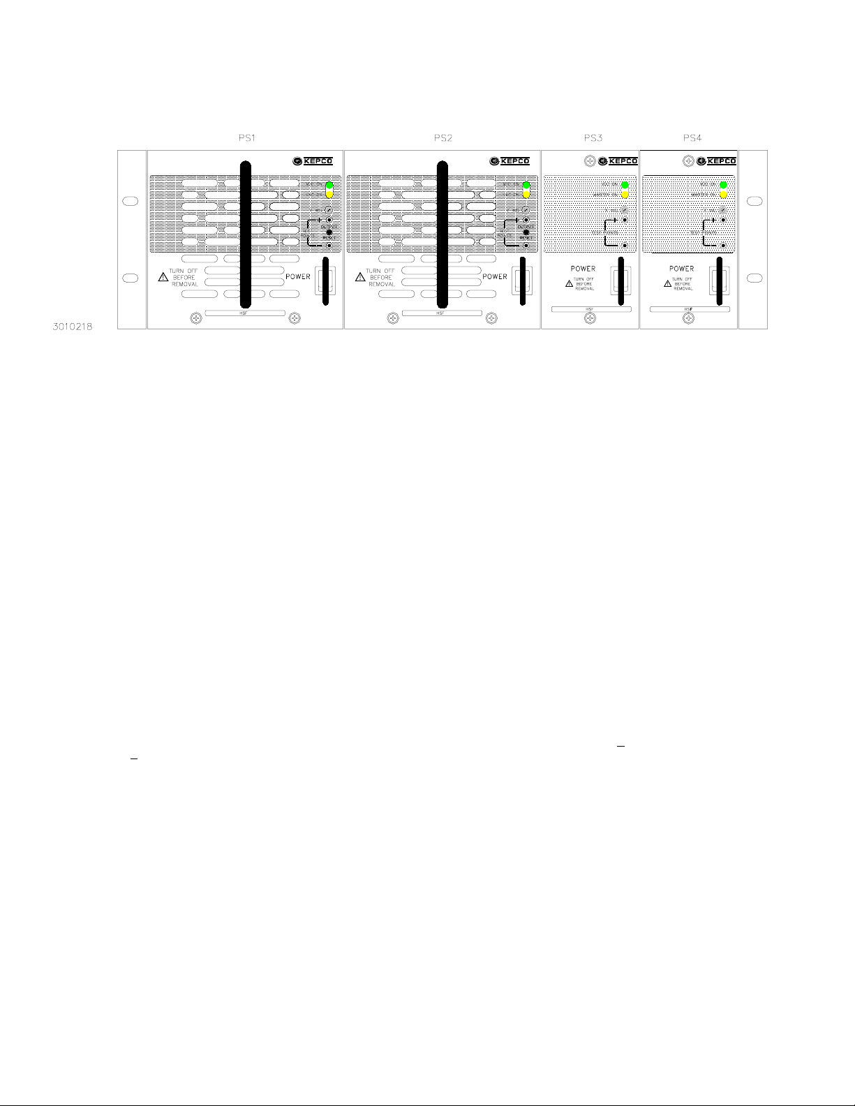
These power supplies are designed to be used with Kepco’s Series RA 19-(X)B rack adapters (Figure 1). The RA 19-3B rack adapter accepts
up to three 350 Watt units; RA 19-4B accepts up to two 350 Watt units and up to two 50W, 100W, or 150W units (see Figure 1). All input/output
connections are through a 24 pin connector that plugs in to the rack adapter. All external connections are made through the rack adapter.
Seven models may be selected for outputs of 3.3, 5, 12, 15, 24, 28, or 48V (see Table 1).
When the input is cut off, the output is maintained for 15 milliseconds minimum. If the power supply shuts down due to an output overvoltage
condition, it is then necessary to wait 90 seconds minimum (120V a-c input) or 120 seconds minimum (240V a-c input) before turning the unit
on again. EMI filtering is designed to meet FCC Class A rating and VDE 0871 Class A rating. This page contains specifications for each model
of the HSF 350 Watt Series. Environmental specifications for each model are the same.
TABLE 1. OUTPUT RATINGS AND SPECIFICATIONS, HSF 350W SERIES
MODEL HSF 3.3-70 HSF 5-70 HSF 12-30 HSF 15-24 HSF 24-16 HSF28-13 HSF 48-7.5
OUTPUT VOLTS, d-c (NOMINAL) 3.3V 5V 12V 15V 24V 28V 48V
ADJUSTMENT RANGE 2.65-3.5 4.0 - 5.5V 9.6 - 13.2V 12.0 - 16.5V 19.2 - 26.5V 22.4 - 30.8V 38.4 - 52.8
(3)
(4)
(2)
(1)
70A 70A 30A 24A 16A 13A 7.5A
230W 350W 360W 360W 384W 364W 360W
<100 <100 <150 <175 <200 <200 <300
4 - 30% 4 - 30% 4 - 30% 4 - 30% 4 - 30% 4 - 30% 4 - 30%
73.0 - 84.0A 73.0 - 84.0A 31.5 - 36.0A 25.2 - 28.8A 16.8 - 19.2A 13.6 - 15.6A 7.8 - 9.0A
OUTPUT CURRENT (NOMINAL)
OUTPUT POWER (NOMINAL)
RIPPLE
AND
NOISE
(mV p-p)
0-40°C
10-100%
LOAD
OVERVOLTAGE SETTING
(0-40 °C, NOM. INPUT)
OVERCURRENT SETTING
(25°C, NOM. INPUT)
Rectangular type characteristic
(1) Derates same as Ouptut Power. (2) See power derating curve, Figure 4. (3) OV setting = % tracking above output. When the output voltage ecxeeds this limit the output is cut
off. To reset the unit it is necessary to remove the ac power, wait 40 seconds, and reconnect the power. However, when the power supply shuts down due to an increase in internal
temperaure the restart cycle should not begin until the temperature returns to within specifications (4) If the output voltage falls to less tha 60% of the rated output voltage for more
than 20 seconds, the output will be cut off. To reset the unit it is necessary to remove the ac power, wait 40 seconds, and reconnect the power.
source (max) 50 50 30 40 40 40 40
switching (typ) 30 30 40 40 60 60 60
switching (max) 50 50 70 70 100 100 100
spike noise
(d-c—50MHz)
II — FEATURES
FRONT PANEL ACCESS.
when the unit is operating. NOTE: The ON/OFF switch must be set to OFF before removing unit from rack adapter. A RESET button
restores output power in the event that overcurrent or overvoltage protection has tripped, or thermal overload or fan malfunction has occurred.
When the unit is used in parallel redundant configurations, the module with the highest voltage functions as the master. The other units are
slaves, and track the output voltage of the master. The front panel Vadj trimmer provides adjustment of the output voltage within the limits
specified in Table 1; test points connected to the +S and –S lines are available at the front panel for measuring the output.
FORCED CURRENT SHARE CIRCUIT.
divided equally among the paralleled supplies. When the CSB (Current Share Bus) lines of paralleled HSF units are connected together, the
load current is forced to divide equally between all paralleled units. If one unit fails, the remaining units will continue to supply the load, and the
load current will be divided equally among the remaining operating units. The failed unit is automatically isolated from the circuit by a built-in
isolation diode.
KEPCO, INC. " 131-38 SANFORD AVENUE " FLUSHING, NY. 11352 U.S.A. " TEL (718) 461-7000 " FAX (718) 767-1102
©2003, KEPCO, INC
Data subject to change without notice
The front panel provides a power ON/OFF switch controlling input power and a “VDC ON” light which indicates
When units are configured for N+1 parallel redundant operation, it is desirable for current to be
http://www.kepcopower.com " email: hq@kepcopower.com
1
228-1367 REV 6
Page 2
ALARM CIRCUIT.
isolated common. These contacts may be used to configure “close on failure” or “open on failure” alarm circuits. (Refer to the Series
RA 19-(X)B Manual for alarm configurations for multiple HSF power supplies.)
KEYING.
corresponding rack adapter key (pin) is installed by the user, only a power supply of the correct voltage can be inserted in the rack adapter
slot.
Keying of the HSF is established at the factory. The output voltage determines which keyway is open (see Figure 5). When the
FIGURE 1. RA 19-4B RACK ADAPTER WITH TWO 1/3 RACK AND TWO 1/6 RACK HSF POWER SUPPLIES INSTALLED.
The HSF includes an isolated internal relay offering normally closed and normally open contacts referenced to an
III — SPECIFICATIONS
The following specifications apply to all HSF 350 Watt Series models (also refer to Table 1). Other models are also available; consult your
Kepco representative for their specifications.
INPUT:
Voltage: 100/120/220/240V a-c nominal; Range 95-264V a-c; 110-370V d-c. (polarity insensitive)
Frequency: Nominal 50-60 Hz; Range 47-440Hz (at 440Hz leakage current exceeds UL/VDE safety spec.limit).
Current (nominal output at rated load): All Models except 3.3V: @120V a-c rms: 4.0A a-c typ., 5.6A a-c max;
3.3V Models: @120V a-c rms: 3.0A a-c typ., 4.0A a-c max;
Initial Turn-on Surge: (one-half of first input cycle): @120V a-c rms, 20A max; @240V a-c rms, 40A max.
When the a-c input power is removed, the inrush current limit circuit requires 30 seconds recovery time before the
a-c input power is reconnected.
Brownout Voltage: 80V a-c, 110V d-c.
Switching Frequency: Main converter (forward):150KHz typical; PFC converter: 120KHz typical, nominal load.
Power Factor: 0.99 typ. (per EN 61000-3-2)
Efficiency: max load, nominal output: All Models except 3.3V: 72% typ.
3.3V Models 65% typ.
STABILIZATION:
Source Effect: Range 95-132V a-c or 190-264V a-c, 0.05% typ.; 0.1% max.
Load Effect: Range 0%-100% load, 0.2% typ.; 0.3% max.
Temperature Effect: Range -10
Combined Effect: 0.7% typ.; 1.5% max. (includes source, load, and temperature effects).
Time Effect: 0.2% typ.; 0.5% max. (1/2 hr-8-1/2 hr, max load at 25
RECOVERY CHARACTERISTICS:
occurs to within +1% of the original setting in <1 ms (load change tr or tf equal to or greater than 10µsec).
START-UP TIME:
HOLDUP TIME:
900 ms. maximum, 500 ms. typ.
30 ms. typ. (120V a-c), 20 ms. min. (120V a-c).
DIELECTRIC STRENGTH:
Between input and output: 2.5KV a-c for one minute.
Between input and output with Y-capacitor removed: 2.5KV a-c for one minute.
Between input and case (ground): 2.5KV a-c for one minute.
INSULATION RESISTANCE:
100 Megohms min. (500V d-c).
o
to 40oC, 0.5% typ.; 1.0% max.
o
C).
A step load change from 50% to 100% produces less than +1% output excursion. Recovery
Between input and ground, output and ground, input and output;
LEAKAGE CURRENT
UL method, 120V a-c: 1.0 mA maximum.
VDE method, 240V a-c: 2.0 mA maximum.
BELLCORE REQUIREMENTS:
SAFETY:
(LVD), 73/23/EEC and 93/68/EEC. [The standards do not apply with DC input operation]
UL1950 3rd. Ed., CSA 22.2 No. M950. Units Designed to meet EN60950 and are CE marked per the Low Voltage Directive
NEBS GR-63-CORE
@240V a-c rms: 2.0A a-c typ., 2.8A a-c max.
@240V a-c rms: 1.5A a-c typ., 2.0A a-c max.
KEPCO, INC. " 131-38 SANFORD AVENUE " FLUSHING, NY. 11352 U.S.A. " TEL (718) 461-7000 "
2
http://www.kepcopower.com " email: hq@kepcopower.com
228-1367 REV 6 040803
FAX (718) 767-1102
B3010218
Page 3

I/O CONNECTOR:
The 24-pin I/O connector (Figure 2) is designed to mate with the corresponding connector in the Series RA 19-(X)B
Rack Adapter.
# (+) SENSE, (–) SENSE: These lines are provided to compensate for voltage drops in the load connecting wires. The Sense lines
must be connected to their respective (+) and (–) output terminals, either at the load or at the rack adapter (see Rack Adapter Manual).
The connection ensures the most accurate error tracking. Error compensation in the connecting wires is up to 0.25 Volts per lead for all
models.
NOTE:
The Sense lines must be connected for the HSF Power supply to work properly!
# OUTPUT (+), OUTPUT (–): HSF power supply d-c output.
# CURRENT SHARE BUS (CSB): Connecting the CSB lines of HSF power supplies operating in a parallel configuration causes out-
put current to be shared equally. (See Rack Adapter Manual for additional information on parallel configurations.). For current sharing to
work properly the outputs of all paralleled units must be within 250 mV (max) of each other. For master/slave operation to work properly
each unit should be adjusted to 40 mV (optimum) less than the next paralleled unit (unit 1 is adjusted to V
and unit 3 to V
minimum of 25 mV as needed to parallel many units and still keep all units within 250 mV of each other. Adjust the outputs using Vadj
– 80mV, etc. If the master fails, the unit 2 will become the new master). The 40 mV difference can be reduced to a
OUT
trimmer on front panel.
• Optimum difference among output voltages of paralleled units: 40mV
• Maximum difference among output voltages of paralleled units: 250 mV
• Minimum difference among output voltages of paralleled units: 25 mV
# ALARM:
referenced to Alarm Common. If the unit fails, the path between Alarm NC - Open on Failure and Alarm Common opens, the path
between Alarm NO - Close on Fail and Alarm Common is a short circuit. Figure 3 illustrates typical Close on Fail and Open on Fail circuits to give a failure indication if any one of a number of power supplies fail.
The Alarm NC (normally closed) - Open on Failure and Alarm NO (normally open) - Close on Failure lines are relay contacts
# INPUT POWER: Line (either a-c or d-c source power), Neutral and Ground (chassis)
Designed to meet FCC (100-120V a-c) Class A
EMI:
(220-240V a-c).
VIBRATION:
5-10 Hz, 10 mm amplitude.
10-55 Hz, 2g acceleration.
SHOCK:
Acceleration: 20g
Duration: 11ms +5ms
OPERATING TEMPERATURE:
STORAGE TEMPERATURE:
OPERATING AND STORAGE RELATIVE HUMIDITY:
bulb temp. <35
FUSE:
Kepco P/N 541-0125
DIMENSIONS:
WARRANTY:
(non-operating, one hour on each one of the three axes):
(non-operating, one-half sinusoidal pulse, three shocks to each axis):
See Figure 4.
-30oC to +75oC.
o
C non-condensing).
up to 95% (wet
Quick acting 10A, 250V; (1-1/4 x 1/4 in.), Little, P/N 314010;
See Figure 5.
5 years.
, unit 2 to V
OUT
OUT
– 40mV,
KEPCO, INC. " 131-38 SANFORD AVENUE " FLUSHING, NY. 11352 U.S.A. " TEL (718) 461-7000 "
http://www.kepcopower.com " email: hq@kepcopower.com
040803 228-1367 REV 6
NOTE: 3.3V AND 5V UNITS USE TWO CONNECTORS.
• LH CONNECTOR IS SHOWN ABOVE.
• RH CONNECTOR PINS 8 THRU 12 AND 20 THRU 24 ARE
AS SHOWN ABOVE; PINS 13 THRU 19 AND 1 THRU 7 ARE
NOT USED. .
FIGURE 2. REAR CONNECTOR PIN
ASSIGNMENTS
FAX (718) 767-1102
3
Page 4

FIGURE 3. TYPICAL ALARM CIRCUIT DIAGRAMS
FIGURE 4. % OUTPUT POWER RATING VS.
AMBIENT TEMPERATURE
FIGURE 5. HSF POWER SUPPLY OUTLINE DRAWING
KEPCO, INC. " 131-38 SANFORD AVENUE " FLUSHING, NY. 11352 U.S.A. " TEL (718) 461-7000 "
http://www.kepcopower.com " email: hq@kepcopower.com
4
228-1367 REV 6 040803
FAX (718) 767-1102
 Loading...