

Page 1
OPERATOR’S MANUAL
HSF A, AM 300 WATTS
POWER SUPPLY
SINGLE OUTPUT POWER SUPPLIES
SINGLE PHASE, POWER FACTOR CORRECTED
UNIVERSAL AC INPUT
KEPCO INC.
An ISO 9001 Company.
HSF A, AM 300 WATTS
POWER SUPPLY
HSF 5-60A, HSF 12-27A, HSF 15-22A,
HSF 24-14A, HSF 28-12A, HSF 48-7A
HSF 5-60AM, HSF 12-27AM, HSF 15-22AM,
HSF 24-14AM, HSF 28-12AM, HSF 48-7AM
IMPORTANT NOTES:
1) This manual is valid for the following Model and associated serial numbers:
MODEL SERIAL NO. REV. NO.
HSF A, AM 300W
2) A Change Page may be included at the end of the manual. All applicable changes and
revision number changes are documented with reference to the equipment serial numbers. Before using this Instruction Manual, check your equipment serial number to identify
your model. If in doubt, contact your nearest Kepco Representative, or the Kepco Documentation Office in New York, (718) 461-7000, requesting the correct revision for your particular model and serial number.
3) The contents of this manual are protected by copyright. Reproduction of any part can be
made only with the specific written permission of Kepco, Inc.
Data subject to change without notice.
MODEL
KEPCO®
©2013, KEPCO, INC
P/N 243-1345-r3
KEPCO, INC. ! 131-38 SANFORD AVENUE ! FLUSHING, NY. 11355 U.S.A. ! TEL (718) 461-7000 ! FAX (718) 767-1102
email: hq@kepcopower.com ! World Wide Web: http://www.kepcopower.com
THE POWER SUPPLIER™
Page 2

TABLE OF CONTENTS
SECTION PAGE
1. Introduction........................................................................................................................................................ 1
1.1 Scope of Manual ............................................................................................................................................ 1
1.2 Description ..................................................................................................................................................... 1
2. Specifications .................................................................................................................................................... 2
3. Features ......................................................................................................................................................... 6
3.1 DIP Switch Configuration ............................................................................................................................... 6
3.2 Front Panel Access. ....................................................................................................................................... 8
3.3 Keying ............................................................................................................................................................ 8
3.4 Output Voltage Control................................................................................................................................... 8
3.4.1 Front Panel Voltage Control ........................................................................................................................ 8
3.4.2 Remote Output Voltage Control ................................................................................................................ 10
3.5 Remote On-Off ............................................................................................................................................. 11
3.6 Protection Circuits ........................................................................................................................................ 12
3.6.1 Overvoltage And Overtemperature Protection .......................................................................................... 12
3.6.2 Overcurrent Setting and Protection ........................................................................................................... 12
3.6.3 Fan Failure ................................................................................................................................................ 12
3.6.4 Undervoltage ............................................................................................................................................. 13
3.7 Alarm Settings .............................................................................................................................................. 13
3.7.1 Visual Alarm. ............................................................................................................................................. 13
3.7.2 Alarm Signals. ........................................................................................................................................... 13
3.7.2.1 Internal Isolated Relay Alarm ................................................................................................................. 13
3.7.2.2 Optically-Coupled Logical Alarm ............................................................................................................ 13
3.8 Local/remote Sensing................................................................................................................................... 15
3.9 Retaining Latches......................................................................................................................................... 15
4. Load Connection ............................................................................................................................................. 15
5. Connecting Multiple Power Supplies ............................................................................................................... 15
LIST OF FIGURES
FIGURE TITLE PAGE
1 HSF (A, AM) Rear Panel Connector and RA 19-4C Rack Adapter I/O Connector..................................... 1
2 Power Rating Vs. Temperature .................................................................................................................. 3
3 Mechanical Outline Drawing of the HSF (A, AM) 300W Power Supply ...................................................... 6
4 DIP Switch Configuration............................................................................................................................ 7
5 Front Panel Controls, Indicators and Test Points (HSF AM, Typical) ......................................................... 9
6 DIP Switch Settings for Control of Output Voltage ................................................................................... 10
7 Connections For Remote Voltage Control ................................................................................................ 11
8 DIP Switch Settings for Using RESET button or Remote ON-OFF .......................................................... 12
9 DIP Switch Settings for Red Alarm Indicator Enable/Disable ................................................................... 13
10 DIP switch settings for Optically Coupled Logical Alarm .......................................................................... 14
11 Output Alarm Circuit Optically Isolated..................................................................................................... 14
12 ±PF Power Failure Optocoupler Timing Diagram..................................................................................... 14
LIST OF TABLES
TABLE TITLE PAGE
1 HSF (A, AM) Rear Connector Pin Assignment ...........................................................................................2
2 HSF 300W (A, AM) Output Ratings and Specifications ..............................................................................3
3 Power Supply Ratings and Specifications ..................................................................................................4
4 DIP Switch 1 and 2 Functions .....................................................................................................................7
5 Minimum Conditions for Relay, Meter and LED Operation .......................................................................11
i HSF(A) 300W 101013
Page 3
1. INTRODUCTION
1.1 SCOPE OF MANUAL
This Operator's Manual covers the installation and operation of the Kepco HSF A and HSF AM
300W Series of Switching Power Supplies. Basic models are identified by the suffix “A” following
the model number; models with the suffix “AM” include an integral voltage/current meter. For service information, write directly to: Kepco Inc., 131-38 Sanford Avenue, Flushing, New York,
11355, U.S.A. Please state Model Designation and Serial Number of your HSF Power Supply.
This information can be found on the nameplate of the unit.
1.2 DESCRIPTION
The Kepco HSF A and AM 300 Watt Series are hot swappable, high frequency switching, plug-in
power supplies that are completely interchangeable with the metered HSF AM Series, as well as
with Kepco’s earlier 300 Watt HSF Series (non A). When integrating A and non A models refer to
PAR’s. 3.5 and 3.7.2.2 regarding isolation of the return signal of the RC and PF features. Unless
otherwise noted, all data supplied herein for A models applies to AM models as well.
Six models may be selected for outputs of 5V, 12V, 15V, 24V, 28V or 48V. They employ forward
conversion and power factor correction and are designed to operate in a fault tolerant power system. Input voltage range is single phase 85-265V a-c (47-63Hz) or 120-330V d-c. Input voltage
which is out of specification may cause unit damage. Safety standards apply when input voltage is
within 100-240V a-c (50-60Hz). A built-in current balancing circuit and OR-ing diodes allow configuration for hot-swap and parallel-redundant N+1 operation.
HSF A (without meter) and AM Models (with meter) use the HSF output to power the VDC ON
indicator and internal alarm relay. A minimum HSF output voltage is needed to maintain functionality for these components. For HSF AM models a minimum output is also needed to power the
meter. Model HSF 5-60AM is the exception, requiring no minimum output to power the internal
relay and meter, and a minimum output of around 3V d-c to power the VDC ON/ALARM indicator.
These power supplies are designed to be used with Kepco's Series RA 19-4C rack adapters. The
RA 19-4C rack adapter accepts up to four 300W modules. All input/output connections are
through a 24-pin connector that plugs in to the rack adapter. All external connections described in
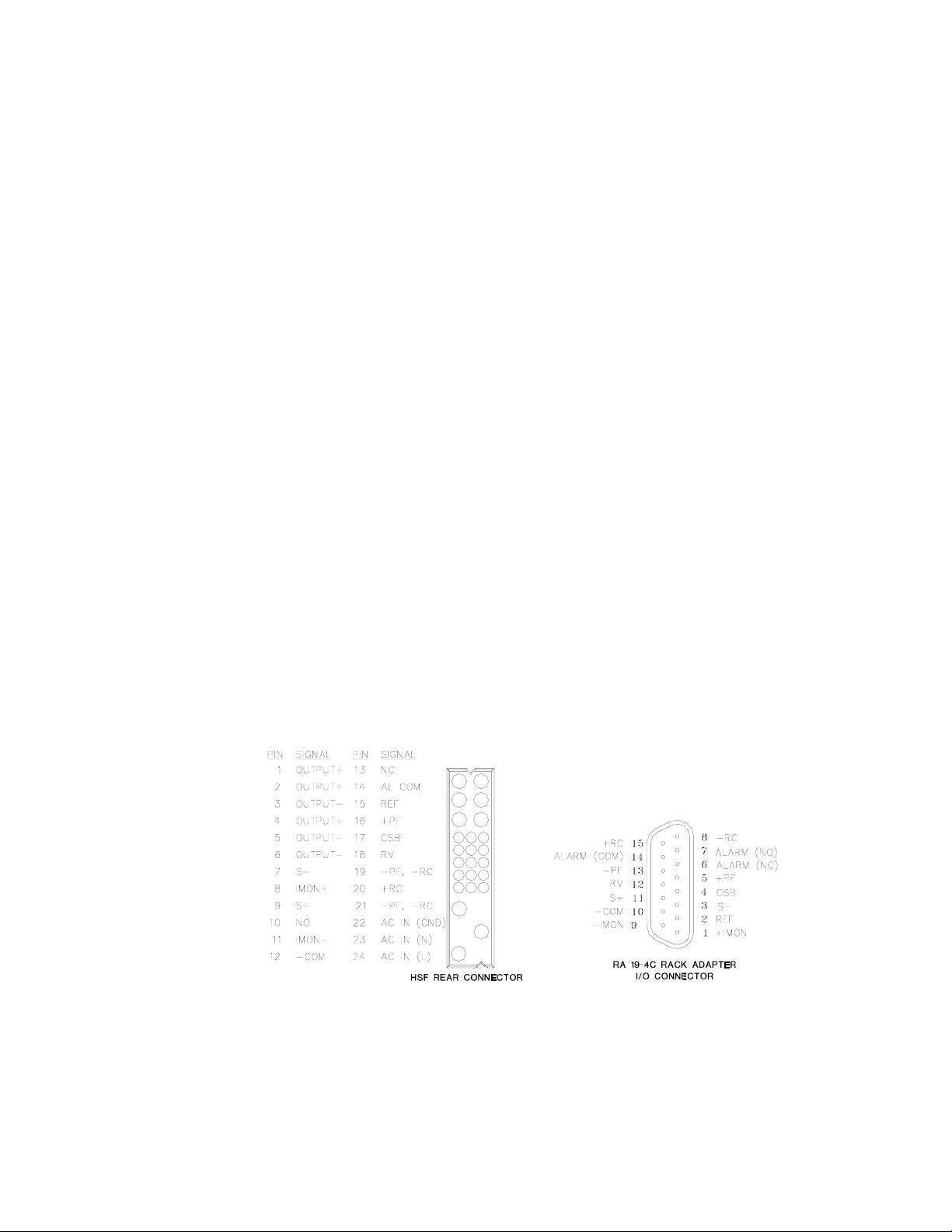
the following paragraphs are made through the rack adapter’s I/O connector (see Figure 1).
21
34
56
897
12 11
10
15
14 13
18 1617
21 20 19
22
23
24
3043790
FIGURE 1. HSF (A, AM) REAR PANEL CONNECTOR AND RA 19-4C RACK ADAPTER I/O CONNECTOR
HSF(A) 300W 101013 1
Page 4

TABLE 1. HSF (A, AM) REAR CONNECTOR PIN ASSIGNMENT
Signal
Name
Output + 1, 2, 4 DC output (+) applied to load.
Output – 3, 5, 6 DC Output (–) applied to load.
SENSE– 7 Sense– connection.
IMON+ 8 Current Monitor+ (sense resistor).
SENSE+ 9 Sense+ connection.
NO 10 Normally Open contact of alarm relay, referenced to AL COM, pin 14 (see PAR. 3.7.2.1).
IMON– 11 Current Monitor– (sense resistor).
–COM 12 –Signal Common provides return for REF, pin 15, and RV, pin 18, signals.
NC 13 Normally Closed contact of alarm relay, referenced to AL COM, pin 14 (see PAR. 3.7.2.1).
AL COM 14 Common contact of alarm relay (see PAR. 3.7.2.1).
REF 15 Reference voltage. When used with RV, pin 18, allows all output voltages of paralleled slave supplies to be
PF 16 Power Fail of open-collector alarm circuit. Used with pins 19, 21 (see PAR. 3.7.2.2).
CSB 17 Current Share Bus - Used whenever several power supplies are connected in parallel (see PAR. 5.).
RV 18 Remote Voltage - Used with REF, pin 15, for remotely controlling the output voltage (see PAR. 3.4.2)
RC and PF
return
RC 20 Remote On-off used pins 19, 21, to allow remote turn-on turn-off of the unit (see PAR. 3.5)
RC and PF
return
GND 22 AC input ground.
N 23 AC Input neutral.
L 24 AC input line.
Pin Function
controlled by one voltage adjustment of a master power supply. When REF is connected to RV via an
external trimmer, the external trimmer determines output voltage (see PAR. 3.4.2). Connections are made
via DIP switches (see PAR. 3.1).
19 Power Fail return of open-collector alarm circuit. Used with PF, pin 16 (see PAR. 3.7.2.2). Connected in
common with pin 21.
21 Remote On-off return for RC, pin 20, to allow remote turn-on turn-off of the unit (see PAR. 3.5). Connected
in common with pin 19.
2. SPECIFICATIONS
Table 2 contains specifications and operating limits of individual HSF (A, AM) 300W Series models. Table 3 contains specifications and operating limits common to all HSF (A, AM) 300W Series
Models. These specifications are at nominal input voltages at 25°C unless otherwise specified.
2 HSF(A) 300W 101013
Page 5
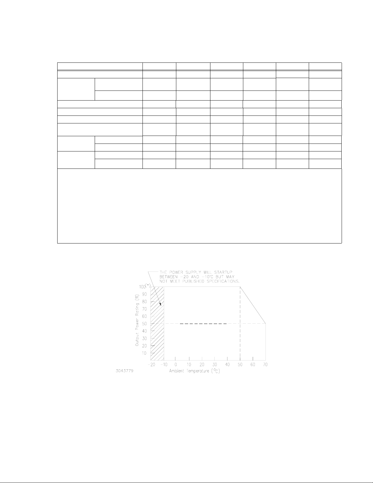
TABLE 2. HSF 300W (A, AM) OUTPUT RATINGS AND SPECIFICATIONS
HSF (A, AM) MODEL 5-60A, AM 12-27A, AM 15-22A, AM 24-14A, AM 28-12A, AM 48-7A, AM
Output Volts d-c (nominal) 5 12 15 24 28 48
Output
Adjustment
(1)
Range
(Volts d-c)
Output Current (nominal) (Amps) 60 27 22 14 12 7
Maximum Output Power (Watts)
Current Limit Setting (Amps)
Overvoltage Protection (OVP)
Efficiency
(% typ.)
Ripple &
(7)
Noise
(mV, p-p)
(1) To adjust output voltage down to approximately 0V requires that DIP SW1, position 7 be set to ON. Refer to Table 5 for mini-
mum conditions required to maintain proper operation of alarm relay, meter (AM Models only) and VDC ON/ALARM indicator.
(2) Using trimpot to attain voltages outside the specified adjustment range may trigger overvoltage (PAR 3.6.1) faults. Recovery
is by removing, and after approximately 40 seconds, reapplying AC input power or by reset (open and close) at ±RC termi-
nals (no delay).
(3) See Figure 2 for power derating.
(4) Square type. Output voltage returns automatically when cause is removed. (see PAR. 3.6.2).
(5) CAUTION: The unit may be damaged if operated under overcurrent or shorted conditions for more than 30 seconds.
(6) When overvoltage is detected, output is shut OFF. Recovery is by removing, and after approximately 40 seconds, reapplying
AC input power or by reset (open and close) at ±RC terminals (no delay).
(7) Ripple and noise levels above are satisfied when conditions are 0 to 100% load, 0 to 50°C (load is derated from 50 to 70°C,
see Figure 2), and bandwidth ≤ 100MHz.
SW1 pos 7 OFF
(default)
(2)
SW1 pos 7 ON 0 to 5.5 0 to 13.8 0 to 17.4 0 to 28.2 0 to 29.0 0 to 52.2
(3)
(4)(5)
(Volts d-c)
(6)
2 to 5.5 4.8 to 13.8 6 to 17.4 9.6 to 28.2 9.6 to 29.0 19.2 to 52.2
300 300 300 300 300 300
63 28.4 23.1 16.7 16.7 7.4
5.75 - 6.75 14.5 - 16.9 18.3 - 21.3 29.5 - 34.3 29.5 - 34.3 54.7 - 63.9
AC Input 100V 71 76 77 80 80 81
AC Input 200V 73 79 80 83 83 84
ripple 80 120 120 150 150 200
ripple noise 120 120 150 150 150 200
FIGURE 2. POWER RATING VS. TEMPERATURE
HSF(A) 300W 101013 3
Page 6

TABLE 3. POWER SUPPLY RATINGS AND SPECIFICATIONS
CHARACTERISTIC SPECIFICATION CONDITION/NOTES
Input Voltage Nominal: 100-120V a-c, 200-240V a-c
Range: 85-265V a-c, 120-330V d-c
Input Source Frequency Nominal: 50-60 Hz
Range: 47-63 Hz
Input Current: (Maximum Load At
25°C with Nominal Output Voltage)
Switching Frequency 200KHz typ. Forward Converter
Input Protection Two thermistors reduce start-up surge. The internal power supply is protected against shorts
Input Surge cold start, interval > 30
sec ( First surge only, not including
current flow into EMI filter )
Leakage Current: 0.75mA max. 240V a-c, 60Hz per IEC 60950 and UL60950
Power Factor Meets EN 61000-3-2 Rated output, rated input
Transient Recovery excursion
characteristic
recovery time 1 ms maximum
Stabilization
Source Effect (min - max) ±0.1% Typical, ±0.2% Maximum 85 to 132V a-c, 170 to 265V a-c
Load Effect ±0.6% Typical, ±1% Maximum (default)
Temperature Effect ±0.5% Typical, ±1.0% Maximum –10° to 50°C
Combined Effect ±1.2% Typical, ±2.2% Maximum Source, Load and Temperature
Time Effect 0.2% Typical, 0.5% Maximum 1/2 to 8 hours at 25°C
Start-up Time 525 msec Typical, 900 msec Maximum 100V a-c
Output Hold-up Time 20 msec Typical (28V model: 15 msec Typical)
Overvoltage Protection When the Power Supply goes into an overvoltage condition, the output is cut OFF. See PAR.
Remote Control ON/OFF: ±RC pins control on/off as follows:
Meter (AM Models only) (displays
voltage or current; front panel
switch-selectable)
Operating Temperature: -10 to 50°C (see Figure 2.)
Startup Temperature -20 to -10°C (see Figure 2.)
Storage Temperature: -30°C to +85°C
Withstanding voltage : (at 15-35°C
ambient, 10-85% relative humidity)
4.2A rms max. 100 - 120V a-c
2.1A rms max. 200 - 240V a-c
by an input fuse. Fuse value 10.0A at 250 Volts
15A typ., 20A max. first surge 100 - 120V ac
30A typ., 40 max. first surge
±4% maximum
±0.6% Typical, ±1% Maximum (see PAR. 5.)
275 msec Typical, 550 msec Maximum 240V a-c
3.6.1.
Must be enabled by DIP switch positions 3
“High”, 2.4V to 12V (or open), unit OFF- Fan
Off;
“Low”, 0.0V to 0.8V (or shorted), unit ON.
Source current: 1.6mA maximum at low level
Sink current: 3.5 mA maximum at high level.
Voltmeter Accuracy: ±3%
Ammeter Accuracy: ±5% for loads between
10%-100%
2500Va-c for 1 minute. Cutout current is 20mA Between input and ground
500Va-c for 1 minute. Cutout current is 100mA Between output and ground
3000Va-c for 1 minute. Cutout current is 20mA Between input and output terminal
and 4 (see PAR. 3.5).
Voltmeter reads sense lines; use remote
sensing to display voltage at load.
Ammeter accuracy degrades significantly for
loads less than 10%
0 to 100% load, -10 to 50°C
CAUTION: Input voltage exceeding
specifications may damage the unit.
0 to 100% load, -10 to 50°C
200- 240 V ac
50% to 100% load,
transient time >50
Individual Mode: 0%-100% load change
Current Sharing: 10%-100% load change
µsec
4 HSF(A) 300W 101013
Page 7

TABLE 3. POWER SUPPLY RATINGS AND SPECIFICATIONS (CONTINUED)
CHARACTERISTIC SPECIFICATION CONDITION/NOTES
Insulation Resistance: (at 25°C,
65% relative humidity)
Humidity: Operating: 10% to 90% relative humidity
Vibration: 5-10 Hz., 10mm amplitude, 10-55 Hz., acceler-
Shock: Acceleration: 643.5ft./s
Safety: Designed to meet UL: 60950-1; CSA:C22.2
EMC Emission - Conducted: Designed to meet FCC Class B, VCCI-Class B, EN55011-B, EN55022-B
EMC Emission - Radiated: Designed to meet FCC Class B, VCCI-Class B, EN55011-B, EN55022-B
EMC Emission - Input harmonics
current:
EMC Immunity Designed to meet EN61000-6-2
EMC Radiated susceptibility: Designed to meet EN61000-4-3 level 3 normal operation
EMC Conducted susceptibility: Designed to meet EN61000-4-6 level 3 normal operation
ESD: EN61000-4-2, level 3 normal operation
Electrical fast transient burst: EN61000-4-4 level 3 normal operation
Surge withstand: EN61000-4-5, level 3 No damage
Power Frequency Magnetic Field: Designed to meet EN61000-4-8, level 4
Voltage dips interruptions and
variations
Dimensions: 5.22 in. (132.5 mm) x 4.288 in. (108.9 mm) x 16.86 in. (428.2 mm) (See Figure 3)
Mounting: Plug-in
Cooling: Forced air flow - fan
Frame Material/Cover Material: Steel
Weight 4.8 lbs, 2.18Kgs. HSF 300 A models
100 Megohms minimum (500Vdc)
Non-operating: 10% to 95% relative humidity
ation 64.3ft./s
2
(19.6M/s2) (2g)
2
(196.1M/s2 ) (20g),
Pulse Duration: 11ms ± 5 msec
Between output and ground, input and
ground, and input and output,
noncondensing,
Wet Bulb temperature <35°C
non-operating 1 hr. on each of 3 axes, sweep
time 10 minutes
(non-operating, 1/2 sine pulse, three shocks
on each axis, Power Supply is fixed on its
bottom side)
Applies when input voltage is:
60950-1; EN60950-1; CE Mark.
100 - 240V a-c, 50-60Hz
Designed to meet EN61000-3-2
normal operation
(HSF 5-60AM: level 3)
EN61000-4-11 normal operation
Semi F47 200V a-c only
5.3 lbs, 2.40Kgs. HSF 300 AM models
HSF(A) 300W 101013 5
Page 8

0.690 [17.5]
SEE
REAR
VIEW
14.667 [372.5]
]
AIRFLOW
0
.
8
2
1
[
0
4
0
.
5
0.093 [2.4]
0.606 [15.4]
1.500
[38.1]
SEE
FRONT
VIEW
0.943 [23.9]
0.085 [2.2]
0.438 [11.1]
0.337 [8.5]
3.353
[85.2]
0.093
[2.4]
2.065
[52.5]
3043321
FIGURE 3. MECHANICAL OUTLINE DRAWING OF THE HSF (A, AM) 300W POWER SUPPLY
3. FEATURES
REAR VIEW
0.093 [2.4]
0.188 [4.8]
3.216 [81.7]
SEE DETAIL "A"
0.090 [2.3]
2.408 [61.2]
0.430 [10.9]
0.127
[3.2]
0.204 [5.2]
0.394
[10.0]
FRONT VIEW
5V
DETAIL "A"
KEYING
15V12V
= PIN PRESENT
= PIN MISSING
24V 28V 48V
4.288 [108.9]
]
5
.
2
3
1
[
8
1
2
.
5
NOTES:
1. MATERIAL:
A) BACKPLATE 0.064" THK. ALUM. 5052-H32
B) PCB 0.063" THK FR-4
C) FRONT PANEL 0.090 THK. ALUM. 6061-T6
2. FINISH:
FRONT PANEL -KEPCO DUAL TONE GRAY
3. MODULE IS KEYED AS SHOWN IN DETAIL
4. DIMENSIONS ARE IN INCHES, [DIMENSIONS IN BRACKETS
ARE IN MILLIMETERS].
3.1 DIP SWITCH CONFIGURATION
The HSF (A, AM) 300W Series incorporates two DIP switches, SW1 and SW2 (see Figure 4),
which must be configured before the unit is installed in the rack adapter. The DIP switch functions
are explained in Table 4.
6 HSF(A) 300W 101013
Page 9

TABLE 4. DIP SWITCH 1 AND 2 FUNCTIONS
DIP Switch 2 (left) DIP Switch 1 (right)
Position Function Position Function
1
1
REF
2
RV
3
+RC
OFF: Front panel Vadj controls output.
See PAR. 3.4.1.
ON: Remote voltage or resistance controls out-
put. See PAR. 3.4.2.
OFF: Allows use of front panel RESET button.
ON: Allows use of remote on/off.
REF
+RC
See PAR. 3.5.
OFF: Allows use of front panel RESET button.
4
-RC
& -PF
5
+PF
ON: Allows use of remote on/off.
See PAR. 3.5.
OFF: Alarm signal from internal isolated relay
contacts. See PAR. 3.7.2.1.
-RC
& -PF
+PF
ON: Enables optically-coupled logic alarm. See
PAR. 3.7.2.2.
6
OFF: Enables Current Share (always off).
(1)
CSB
-COM
to -S
PVB
Disable
ON: N/A
OFF: Isolates -COM from -S.
7
ON: Connects -COM to -S.
8
OFF: Enables current sharing (always off)
(2)
ON: N/A
CSB
VAD J
to 0
Alarm
LED
NOTE: BOLD settings indicate factory defaults.
(1) CSB (Current Share Bus bypass) must be in factory default position to enable current sharing.
(2) PVB (Programming Voltage bypass) must be in factory default position to enable current sharing.
OFF: Remote voltage or resistance controls output.
See PAR. 3.4.2.
ON: Front panel Vadj controls output.
2
RV
3
See PAR. 3.4.1.
OFF: Allows use of remote on/off.
ON: Allows use of front panel RESET button.
See PAR. 3.5.
OFF: -PF and -RC isolated from PF/RC Common.
4
ON: -PF and -RC connected to PF/RC Common.
See PAR. 3.7.2.2.
5
OFF: Enables optically-coupled logic alarm.
See PAR. 3.7.2.2.
ON: Alarm signal from internal isolated relay con-
tacts. See PAR. 3.7.2.1.
6
OFF: N/A
(1)
ON: Enables Current Share (always on).
OFF: Vadj adjusts output per Table 2.
7
ON: Vadj adjusts output to zero.
See Par. 3.4.1.
OFF: VDC ON/ALARM stays off for parallel condition.
8
ON: VDC ON/ALARM glows red for alarm condition.
See Par. 3.7.1
FACTORY DEFAULT SETTINGS:
- Front Panel V
- V
ADJ Adjust to zero disabled
ADJ control of output
- Relay Alarm selected
- Visual (red) ALARM indicator enabled
- Front Panel RESET button enabled
- Remote ON-OFF disabled
- Current Share enabled
-RC AND -PF
(Always set to OFF) CSB
-COM TO -S
CSB DISABLE
(Always set to OFF)
3043768
- (-PF) and (-RC) connected to (-OUT)
- (-COM) connected to (-S)
REF
+RC
+PF
OFF
ON
1
2
RV
3
4
5
6
7
8
SW2
OFF
ON
1
1
2
2
3
3
4
4
5
5
6
6
7
7
8
8
TAB
SW1
1
2
3
4
5
6
7
8
REF
RV
+RC
-RC AND -PF
+PF
CSB (Always set to ON)
VADJ TO ZERO
ALARM LED ENABLE
NOTE: NOT ALL COMPONENTS SHOWN.
DETAIL VIEW
SW1SW2
SEE DETAIL VIEW
FIGURE 4. DIP SWITCH CONFIGURATION
HSF(A) 300W 101013 7
Page 10

3.2 FRONT PANEL ACCESS.
The front panel provides a power ON/OFF switch controlling input power and a “VDC ON” indicator which lights green when the unit is operating. If the unit is connected in a parallel configuration,
the indicator lights red if the unit shuts off automatically, or the POWER switch is set to OFF.
CAUTION: DO NOT repeatedly toggle the power ON/OFF switch as this may cause unit to
fault.
NOTE: The ON/OFF switch must be set to OFF before removing unit from rack adapter.
If remote on-off is not enabled (see PAR. 3.5), the OUTPUT RESET button restores output power
in the event that overcurrent or overvoltage protection has tripped, or thermal overload or fan malfunction has occurred.
If remote voltage control (see PAR. 3.4.2) is not enabled, the front panel Vadj trimmer (see PAR.
3.4.1) provides adjustment of the output voltage within the limits specified in Table 2; test points
are available at the front panel for monitoring the DC output.
Figure 5 shows the location of all operating controls, indicators and test points followed by an
explanation of each.
3.3 KEYING
Keying of the HSF (A, AM) 300W is established at the factory. The output voltage determines
which key pins are installed (see Figure 3, Detail A). When the proper holes in the rack adapter
are blocked by keying screws installed by the user, only a power supply of the correct voltage can
be inserted in the rack adapter slot. Refer to the RA 19-4C Manual for rack adapter keying instructions.
3.4 OUTPUT VOLTAGE CONTROL
Output Voltage can be controlled from either the front panel (PAR. 3.4.1) or externally using a
trimpot or voltage source (PAR. 3.4.2).
3.4.1 FRONT PANEL VOLTAGE CONTROL
Output voltage can be manually adjusted with the voltage adjustment control, Vadj (see Figure 5
for location). Configuration options are as follows:
Output from maximum to minimum specified in Table 2 (Figure 6A (factory default)).
SW1: pos 1 to ON, pos 2 to ON;
SW2: pos 1 to OFF, pos 2 to OFF, pos 7 to OFF
Output from maximum to 0V (requires multiple turns of Vadj for full range)
SW1: pos 1 to OFF, pos 2 to OFF
SW2: pos 1 to ON, pos 2 to ON, pos 7 to ON
To adjust voltage, first place the unit under an operating load. Then monitor the (+) and (–) test
points on the front panel with a precision voltmeter and turn the voltage control to the desired
operating value.
The minimum output voltage required to ensure proper operation of the alarm relay, meter (on AM
models) and LED indicator is listed in Table 5.
8 HSF(A) 300W 101013
Page 11

Voltage/Current Meter
Meter Mode switch
V (Voltage) indicator
A (Amperes) indicator
3043129
• VDC ON/ALARM indicator. Lights green when unit is oper-
• V.ADJ Output voltage adjustment trimmer: Adjusts out-
• TEST POINT (+, –): Connect to voltmeter to monitor d-c
VDC ON/ALARM Indicator
V. ADJ Output Voltage Adjustment Trimmer
TEST POINT (+)
OUTPUT RESET switch
TEST POINT (-)
POWER ON/OFF switch
Retaining Latches
ating. When enabled by DIP switch configuration, lights
red to indicate loss of output voltage in parallel configuration only (see PAR. 3.7.1).
put voltage within limits specified in Table 2 (see PAR.
3.4.1). Not functional if remote output control is enabled
(see PAR. 3.4.2).
output voltage.
• OUTPUT RESET switch. Used to recycle power in the
event of an alarm condition (see PAR. 3.6). Not functional when remote on/off control is enabled (see PAR.
3.5).
• POWER ON/OFF switch. Applies power to the unit. CAU-
TION: Power must be OFF before unit is removed
from the rack adapter.
• Retaining Latches (2). Prevents inadvertent removal of
unit from rack adapter (see PAR. 3.9).
• AM Models only: Voltage/Current meter: Monitors output voltage or current according to setting of Meter Mode
switch. NOTE: Use remote sensing for voltmeter to display voltage at the load.
• AM Models only: Meter Mode toggle switch: Set to V for
display to show output voltage, set to A to show output
current.
• AM Models only: V indicator: Lights green to indicate
meter is showing Volts.
• AM Models only: A indicator: Lights amber to indicate
meter is showing Amperes.
FIGURE 5. FRONT PANEL CONTROLS, INDICATORS AND TEST POINTS (HSF AM, TYPICAL)
HSF(A) 300W 101013 9
Page 12

3.4.2 REMOTE OUTPUT VOLTAGE CONTROL
Output voltage can be controlled remotely by means of an external voltage or resistance instead
of by Vadj. Configure the DIP switches as follows:
SW1: pos1 to ON, pos2 to ON; SW2: pos 1 to OFF, Pos2 to OFF
NOTE: Configuring the unit for remote output voltage control disables the front panel Vadj con-
trol. To restore Vadj control, configure the DIP switches per PAR. 3.4.1.
When DIP switch positions 1 and 2 are configured as noted above, output voltage can be adjusted
by either an external trimmer pot (resistance) or by an external variable voltage source as shown
in Figure 7. At the rack adapter I/O connector use a shielded wire 6.6 feet (2M) maximum in
length, for connection of pin 2 (REF, Reference), pin 12 (RV, Remote Voltage), and pin 10 (–COM,
Common) of the rack adapter I/O connector to the trimmer control or external voltage source.
Using External Voltage to Control the Output. Connect the external voltage source across the
RV and –COM pins as shown in Figure 7B. By adjusting an external 0 to 6V voltage source (0 to
5.5V for the 48V model), the HSF (A, AM) output voltage can be adjusted within the range specified
in Table 2. To ensure proper operation of the alarm relay, meter (AM Models only) and VDC ON/
ALARM indicator, do not adjust the external voltage below minimum listed in Table 5.
Using External Resistance to Control the Output. Connect the unit to the RV, –COM and REF
pins as shown in Figure 7A. Suggested value for the trimmer control is 20K ohms. Referring to
Figure 7A, Resistor R is used to obtain minimum output voltage required to ensure proper operation of the alarm relay, meter (AM Models only) and VDC ON/ALARM indicator; see Table 5 for
values.
NOTE: Output voltage may not adjust to 0V due to residual trimmer resistance.
NOTE: If remote output control is not implemented, the factory default for positions 1, 2 and 7
of DIP switches SW1 and SW2 must be restored (Figure 6A).
A
FRONT PANEL OUTPUT VOLTAGE CONTROL
TAB
REF 1
RV 2
3043769
NOTE: SWITCH POSITIONS NOT SHOWN HAVE NO EFFECT ON DESCRIBED FUNCTION.
USING Vadj CONTROL
(FACTORY DEFAULT)
OFF
ON
1
2
OFF
ON
1
2
7
1 REF
2 RV
7 VADJ
TO ZERO
SW1SW2
FIGURE 6. DIP SWITCH SETTINGS FOR CONTROL OF OUTPUT VOLTAGE
REMOTE OUTPUT VOLTAGE CONTROL
USING EXTERNAL TRIMPOT
OR VOLTAGE SOURCE
OFF
REF 1
RV 2
SW2
ON
B
OFF
ON
1
1
2
2
SW1
1 REF
2 RV
NOTE: It is possible that overvoltage protection may be triggered if the output voltage is
decreased to a low level very quickly when the power supply is at a low load condition.
10 HSF(A) 300W 101013
Page 13

TABLE 5. MINIMUM CONDITIONS FOR RELAY, METER AND LED OPERATION
O
HSF A, AM MODEL 5-60A, AM 12-27A, AM 15-22A, AM 24-14A, AM 28-12A, AM 48-7A, AM
For HSF A and AM models, minimum
output voltage required for continuous
alarm relay, meter (AM Models only) and
VDC ON indicator functioning (Volts d-c)
(1)(2)
Minimum resistance of Limit resistor R
(Figure 7A) in series with 20K ohm Trimpot to ensure proper operation of alarm
relay, meter (AM Models only) and VDC
ON indicator (Ohms).
(1)(2)
Minimum external voltage (Figure 7B) to
ensure proper operation of alarm relay,
meter (AM Models only) and VDC ON
indicator (Volts d-c).
(1)(2)
Voltage source range (Volts d-c) 0 - 6 0 - 6 0 - 6 0 - 6 0 - 6.25 0 - 5.5
(1) For model HSF 5-60AM, 3V d-c minimum output is required for VDC ON/ALARM indicator to function, no minimum required
for alarm relay and meter to function. VDC ON/ALARM indicator brightness is dimmer than other models. This is normal.
(2) If operating below minimums listed, see PAR. 3.7.2.2 to implement ±PF alarm signals to monitor power supply status.
(1)
4.5
67777
36K 11.2K 9.76K 5.36K 5.36K 2.49K
4.5 2.5 2.33 1.46 1.46 0.73
RA 19-4C
RV REF
-COM
J2
I/O 1
1012 2
VOLTAGE
SOURCE
(SEE NOTE)
LOAD
(SEE TABLE 4
REMOTE VOLTAGE
CONTROL USING
EXTERNAL VOLTAGE
NOTE: SEE TABLE 5 FOR
MINIMUM VALUE.
REMOTE VOLTAGE
CONTROL USING
EXTERNAL RESISTANCE
RA 19-4C
RV REF
HSF SLOT 1
-COM
J2
I/O 1
10212
(SEE TABLE 5
FOR VALUES)
TABLE 4 F
R
-+ -+
LOAD
(SEE
R
FIGURE 7. CONNECTIONS FOR REMOTE VOLTAGE CONTROL
3.5 REMOTE ON-OFF
When power is ON at the source, the output may be turned ON or OFF using the ±RC signals if
the remote ON-OFF feature is enabled. Note that when remote ON-OFF is enabled, the RESET
OUTPUT switch does not function. Remote ON-OFF is enabled by setting DIP switch positions 3
and 4 as shown in Figure 8B. The +RC and –RC signals (at the rack adapter I/O connector, pins
15 and 8, respectively) then turn the unit on or off.
These pins accept a logic level (2.4V to 12V “high” and 0.0 to 0.8V “low”), or a contact closure.
When the ±RC pins are open, using either a mechanical switch or a high level logic signal, the
HSF (A, AM) 300W output is cut OFF. When the ±RC pins are shorted, the output returns to within
specifications. At low level logic, the maximum sink current is 3.5mA.
Positions 3 and 4 of both DIP switches must be restored to the factory default setting (Figure 8A)
if remote ON-OFF is not used.
NOTE: The +RC pin is not isolated from DC output. –PF and –RC are connected together
and cannot be isolated from each other (unlike earlier (non A) HSF 300W models).
This return is connected to the power supply –OUTPUT. Please contact Kepco if application requires remote control to be isolated from DC output or from PF signal.
HSF(A) 300W 101013 11
Page 14

TAB
USE FRONT PANEL
RESET BUTTON
(FACTORY DEFAULT)
OFF
ON
A
OFF
ON
B
USE REMOTE ON-OFF
(LOGICAL LEVEL OR
MECHANICAL SWITCH)
OFF
ON OFF
ON
+RC 3
-RC & -PF 4
3043784
3
3
4
4
SW2 SW1
3 +RC
4 -RC & -PF
+RC 3
-RC & -PF 4
SW2
3
3
4
4
3 +RC
4 -RC & -PF
SW1
FIGURE 8. DIP SWITCH SETTINGS FOR USING RESET BUTTON OR REMOTE ON-OFF
3.6 PROTECTION CIRCUITS
The following protection features are implemented in the HSF (A, AM) 300W Series: overvoltage
and overtemperature (PAR. 3.6.1), overcurrent (PAR. 3.6.2), fan failure (PAR. 3.6.3), and undervoltage (PAR. 3.6.4). The HSF (A, AM) 300W Series provides a configurable visual alarm (see
PAR. 3.7.1) as well as an option to use either relay contacts or logic levels for alarm signals (see
PAR. 3.7.2)
3.6.1 OVERVOLTAGE AND OVERTEMPERATURE PROTECTION
When the output voltage of the HSF (A, AM) 300W Power Supply increases beyond the specified
values (see Table 2), at some point the output is cut OFF and the fan turns OFF. To restart (reset)
the unit, press and release the OUTPUT RESET switch on the front panel or, if the remote on/off
feature is in use (see PAR. 3.5), open connection between the ±RC pins and then reconnect the
pins. The unit may also be restarted by turning the POWER ON/OFF switch to OFF, waiting 40
seconds, then setting the POWER switch to ON.
When internal temperature of the HSF (A, AM) 300W Power Supply increases beyond the allowable limit, the output is cut OFF and the fans turn OFF. The restart cycle (Power ON) should not
begin until the temperature returns to within specifications. To restart (reset) the unit, set the
POWER ON/OFF switch to OFF, wait until unit cools, then set the POWER switch to ON. The
power supply cannot be reset using the remote ON-OFF feature unless the power supply remains
shut down for at least 40 seconds.
3.6.2 OVERCURRENT SETTING AND PROTECTION
The Overcurrent Protection (OCP) characteristic is constant current limiting, automatic recovery.
OCP operates when output current exceeds 105% (119% for 24V model) of maximum d-c output
current specification. The output automatically recovers when the overload condition is removed.
CAUTION: Operating the unit under overcurrent or shorted conditions for more than 30
seconds may damage the unit.
The OCP setting is fixed and is not user-adjustable.
3.6.3 FAN FAILURE
A cutoff of the fan supply voltage or a decrease in fan speed causes the output to shut down and the
fans to turn OFF. Fan failure and all the other protection circuit operations produce an alarm (see
PAR. 3.7.2). To restart (reset) the unit, press and release the OUTPUT RESET switch on the front
panel or, if the remote on/off feature is in use (see PAR. 3.5), open the connection between the
±RC pins and then reconnect the pins. The unit may also be restarted by turning the POWER ON/
OFF switch to OFF, waiting 40 seconds, then setting the POWER switch to ON. If fan rotation is
out of specification the power supply will not recover.
12 HSF(A) 300W 101013
Page 15

3.6.4 UNDERVOLTAGE
If power supply output voltage either falls within 40 to 80% of the rated output voltage value, or is
programmed below the minimum values listed in Table 5, an alarm occurs if the internal relay
alarm (factory default, see PAR. 3.7.2.1) is enabled. To restart (reset) the unit, press and release
the OUTPUT RESET switch on the front panel or, if the remote on/off feature is in use (see PAR.
3.5), open the connection between the ±RC pins and then reconnect the pins. The unit may also
be restarted by turning the POWER ON/OFF switch to OFF, waiting 40 seconds, then setting the
POWER switch to ON. To enable the alarm function when operating below the minimum values
listed in Table 5, refer to PAR. 3.7.2.2 to configure the optically-coupled alarm.
3.7 ALARM SETTINGS
3.7.1 VISUAL ALARM.
When the unit is connected in a parallel configuration, the front panel VDC ON/ALARM indicator is
normally configured to light red if the respective power supply output voltage is lost or if the
POWER switch is set to OFF. This is enabled when DIP switch 1, position 8 is set to ON (see Figure 9A. This can be useful to indicate the loss of output voltage from one parallel-connected
power supply that may not be readily apparent. For the visual alarm to function properly the minimums specified in Table 4 must be observed.
RED ALARM INDICATOR ENABLED
(FACTORY DEFAULT)
OFF
ONONOFF
TAB
8
3043783 SW1SW2
FIGURE 9. DIP SWITCH SETTINGS FOR RED ALARM INDICATOR ENABLE/DISABLE
8 ALARM LED ENABLE
SW1SW2
RED ALARM INDICATOR DISABLED
OFF
A
B
ON OFF
8
ON
8 ALARM LED ENABLE
If desired, the red alarm indication of the VDC ON/ALARM indicator can be disabled by setting DIP
switch 1 position 8 to OFF.
3.7.2 ALARM SIGNALS.
Either of two options are available for signalling alarms: isolated relay contacts (factory default,
PAR. 3.7.2.1) or logic level alarm signals ±PF (PAR. 3.7.2.2). The ±PF logic level alarm option
must be used if the power supply is intended to operate below the minimum voltages listed in
Table 5.
3.7.2.1 INTERNAL ISOLATED RELAY ALARM
The first option, the factory default setting, uses an isolated internal relay offering normally closed
(NC) and normally open (NO) contacts referenced to an isolated common (AL COM). These contacts may be used to configure “close on failure” or “open on failure” alarm circuits. (Refer to the
Series RA 19-4C Manual for alarm configurations for multiple HSF (A, AM) power supplies.) Setting position 5 of the DIP switches as shown in Figure 10A selects this option. The NC (pin 6 of the
rack adapter I/O connector) and NO (pin 7) signals are referenced to Alarm common (pin 14).
3.7.2.2 OPTICALLY-COUPLED LOGICAL ALARM
The second option uses optically-coupled logic level alarm signals, +PF (pin 5 of the rack adapter
I/O connector) and -PF (pin 13), provided directly from the internal power supply that is the heart
of the HSF (A, AM) power supply. The optically-coupled logic alarm is selected by setting position
5 of the DIP switches as shown in Figure 10B. This option functions even with output voltage
adjusted below the minimum voltages specified in Table 5.
HSF(A) 300W 101013 13
Page 16

NOTE: Unlike earlier (non A) HSF 300W models, –PF and –RC are connected together
and cannot be isolated from each other. This return is connected to the power supply –OUTPUT when position 4 of SW1 is set to ON (factory default). If it is necessary to isolate –PF and –RC from the power supply output, set position 4 of SW1 to
OFF.
USE N.O. AND N.C CONTACTS
OF INTERNAL RELAY
(FACTORY DEFAULT)
OFF
ON
TAB
A
OFF
ON
USE OPTICALLY-COUPLED
OFF
B
LOGICAL ALARM
(+PF AND -PF)
ON OFF
ON
3043770
+PF 5
SW2
5
5
5 +PF
SW1
+PF 5
55 +PF
5
SW1SW2
FIGURE 10. DIP SWITCH SETTINGS FOR OPTICALLY COUPLED LOGICAL ALARM
The logic alarm circuit is a diode transistor optical coupler (see Figure 11). The transistor is normally conducting. When the alarm is activated upon detection of power loss, overvoltage, fan
fault, overtemperature or overcurrent condition, the transistor cuts off and the collector emitter circuit is open. Figure 12 is a timing diagram of the power fail signal.
The default state of the alarm is logic low. The sink current for the optocoupler is 50mA maximum,
the maximum collector to emitter saturation voltage is 0.40 Volts, and the collector to emitter voltage is 40 volts maximum. The +PF signal is isolated from the AC input and DC output. The –PF
signal (in common with –RC) is connected to –OUTPUT when position 4 SW1 is set to ON (factory default). It is possible to isolate both –PF and –RC from –OUTPUT by setting SW1 of position
4 to OFF.
FIGURE 11. OUTPUT ALARM CIRCUIT OPTICALLY ISOLATED
FIGURE 12. ±PF POWER FAILURE OPTOCOUPLER TIMING DIAGRAM
14 HSF(A) 300W 101013
Page 17

3.8 LOCAL/REMOTE SENSING
HSF (A, AM) 300W Power Supplies allow remote error sensing which can compensate up to 0.4
Volts per load wire. Local/Remote error sensing is configured by means of separate DIP switches
mounted on the RA 19-4C Rack Adapter (see RA 19-4C Rack Adapter Operator Manual). Either
local or remote sensing MUST be used, otherwise the units will not operate.
3.9 RETAINING LATCHES
HSF (A, AM) 300W series power supplies are provided with (2) retention latches located at each
side of the bottom edge of the front panel (see Figure 5). These latches work in conjunction with
the RA 19-4C rack adapters to prevent unauthorized or inadvertent module extraction from an
operating power system. The latch is engaged by loosening the cap-head screw approximately 1/
2 turn CCW (use 5/32” hex key) and sliding the latch down to the bottom of the slot, then retightening the cap-head screw CW until snug. DO NOT OVERTIGHTEN! To release, follow the same
procedure, except lift the latch to the top of the slot. Be sure to move the latch completely up or
down to ensure full engagement and disengagement of the latching mechanism. When the HSF
(A, AM) power supply is not installed in its plug-in rack adapter, it is recommended that the latch
be secured in the open (up) position to prevent damage.
NOTE: Retaining latches must not be used to secure the HSF (A, AM) power supply in the
rack adapter for shipping purposes.
4. LOAD CONNECTION
Connect the load to (+) and (–) terminals at the rear panel of the Rack Adapter (see RA 19-4C
Instruction Manual for details).
5. CONNECTING MULTIPLE POWER SUPPLIES
All connections to multiple HSF (A, AM) power supplies must be made via the I/O mating connectors at rear of the Rack Adapter or by the Rack Adapter DIP switches. These connections, including the configuration of the two internal HSF (A, AM) DIP switches, are described in the Rack
Adapter Instruction manual, and include:
• Using one power supply to control the output of multiple supplies.
• Using parallel master/slave configurations (for increased current or redundancy) where
the user either predetermines the master or allows the load to determine which is the
master. These configurations also cover the use of the Current Balancing feature of the
HSF (A, AM) power supply.
• Using series configurations (for increased voltage).
• Using open-on-fail or close-on-fail alarm schemes with multiple power supplies.
NOTES: 1. To enable current share, the difference between voltage settings of parallel con-
nected units should be less than 0.5% of the nominal voltage value of the units.
Output voltage adjustment should be done at same load for each unit.
2. An overshoot of about 1% of nominal voltage occurs upon power up of each unit.
When powering up with no load, overshoot may last up to 15 seconds and alarm
may be temporarily triggered on one of the other parallel-connected units.
3. Load effect specifications will not be met when units are operated in redundant
mode with load less than 10% per unit.
4. Minimum Load. A minimum load is required to operation without voltage set
restrictions (see Note 5, below). The minimum load is defined as:
minimum load (Amperes) = N x (I/10)
where N = the number of units in parallel,
I = Nominal current rating of individual power supply (Amperes).
HSF(A) 300W 101013 15
Page 18

5. Voltage Set Restrictions. When units are at light load (under 10% of nominal),
and voltage settings are less than 80% of nominal, voltage set restriction are
required. To avoid a “slave idle” condition (PF signal set, red ALARM indicator on)
the output voltage of all parallel-connected units must be set within 0.5% of each
other and be at least 80% of their nominal (rated) output voltage (90% for 48V
model).
16 HSF(A) 300W 101013
 Loading...