

Page 1
QUICK START GUIDE
KEPCO
An ISO 9001 Company.
SINGLE OUTPUT 1U
HOT SWAP PLUG-IN POWER SUPPLIES
I — INTRODUCTION
SCOPE OF MANUAL. This Quick Start Guide covers
the installation and operation of the Kepco HSF-1UR
Series of Hot Swap Plug-in Power Supplies. Full specifications are listed in the applicable 50W, 100W or 150W HSF1UR Operator Manual that can be downloaded from the
Kepco web site at:
www.kepcopower.com/support/opmanls.htm#hsf1ur
These power supplies are designed to be installed in
Kepco’s RA 19-1U Rack Adapter. The RA 19-1U Operator
Manual can be downloaded from the Kepco web site at:
www.kepcopower.com/support/opmanls.htm#ra19-1u
DESCRIPTION. The Kepco HSF-1UR Series power supplies come in 50W, 100W and 150W power ratings. Each group has 3.3V, 5V, 12V, 15V, 24V, 28V and 48V models (the 28V 50W models are only available on T, X, C and Y options). Power Factor Correction (PFC) is included in all models.
HSF
-1UR
Units may be operated with a nominal 120V a-c/240V a-c
(input voltage range 95 to 264 Va-c), 50-60 Hz (input frequency range 47-440Hz (at 440Hz leakage current
exceeds UL/VDE safety spec. limit). They will also operate
on 125V to 370V d-c input. Overvoltage protection is provided. Current limiting with automatic recovery from short
circuit is featured. The 100W and 150W 3.3V units and all
50W models are convection cooled; all other 100W and
150W units use forced convection, ball-bearing fans, life
expectancy 50,000+ hours.
OPTIONS. C option (-1URC) models include a current sensing resistor, allowing current monitoring within ±10% (contact Kepco if greater accuracy is required). X option models (-1URX) include the ability to turn the unit on/off from a remote location. Y Option models (-1URY) include both the current sensing resistor and remote on/off capabilities. T Option models (-1URT for 50W Series only) weigh less, and have improved efficiency (input current) specifications as well as one additional model (28V).
TABLE 1. HSF -1UR HOT SWAP MODELS
SIZE
50W HSF 3.3-10-1UR HSF 5-10-1UR HSF 12-4.3-1UR HSF 15-3.5-1UR HSF 24-2.2-1UR * HSF 48-1.1-1UR
100W HSF 3.3-25-1UR HSF 5-20-1UR HSF 12-8.4-1UR HSF 15-6.7-1UR HSF 24-4.2-1UR HSF 28-3.5-1UR HSF 48-2-1UR
150W HSF 3.3-30-1UR HSF 5-30-1UR HSF 12-12-1UR HSF 15-10-1UR HSF 24-6.3-1UR HSF 28-5.3-1UR HSF 48-3.1-1UR
* MODELS HSF 28-1.8-1URT, HSF 28-1.8-1URX, HSF 28-1.8-1URC and HSF 28-1.8-1URY only.
3.3V 5V 12V 15V 24V 28V 48V
II — INSTALLATION
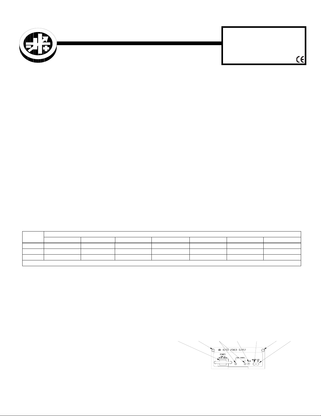
MOUNTING THE POWER SUPPLY. Refer to Figure
and insert HSF-1UR power supply in selected slot until
power supply front panel is flush with rack adapter chassis
and secure with two front panel mounting screws.
CAUTION: Do not overtighten these screws: max.
MODELS
REMOVAL. To remove a power supply, first use the POWER switch to turn off the unit. Then loosen the two mounting screws and extract the unit from the RA 19-1U Rack Adapter. CAUTION: The ON/OFF switch must be
set to OFF before removing the unit from the rack
adapter.
torque is 2 in.-lbs (0.23 N x m).
NOTE: MOUNTING SCREW MAX TORQUE: 2 IN.-LBS. (0.23 N x m)
CONNECTIONS. All connections are made at the rear panel of the RA 19-1U Rack Adapter (see RA 19-1U Operator Manual). Connect the load to the applicable ± DC
POWER
SWITCH
MOUNTING
SCREW
POINTS
TEST
VOLTAGE
ADJUST
TRIMMER
MASTER
ON
LED
MOUNTING
SCREW
OUTPUT terminals. AC input power is applied via two
INPUT POWER terminal blocks: one supplying slots 2 and
4, the other supplying slots 1 and 3. Make sure to connect
the AC input Neutral, Line and Ground wires to the respec-
3043412
tive terminals of the terminal blocks.
FIGURE 1. COMPONENT LOCATIONS
VDC
ON
LED
KEPCO, INC. 131-38 SANFORD AVENUE FLUSHING, NY. 11355 U.S.A. TEL (718) 461-7000 FAX (718) 767-1102
http://www.kepcopower.com email: hq@kepcopower.com
©2010, KEPCO, INC 1
Data subject to change without notice 228-1675 REV 1
Page 2
III — OPERATION
Turn the unit on using the front panel POWER switch (see
Figure 1). CAUTION: DO NOT repeatedly toggle the
POWER on/off switch as this may cause unit to fault.
When output voltage is available, the VDC ON LED is on
(green). For 100W and 150W 5V through 48V models the
VDC ON LED lights red to indicate a fan malfunction. The
100W 3.3V model and all 50W models use convection
cooling and do not include a fan.
While monitoring output voltage at the front panel test
points, the Output Voltage Adjust trimmer allows adjustment of the output voltage.
The 3.3V models do not use forced current sharing so the
MASTER ON LED is always off. The MASTER ON LED
for 5V through 48V models goes on under any of the three
following conditions:
• Independent operation.
• Operation in a parallel master/slave configuration
to indicate which unit is the master
to indicate that a slave unit is no longer within the
proper specifications for paralleled units. Slave 1
should be optimally adjusted to 40mV less than
master, slave 2 adjusted to 40mV less than slave
1, etc. The maximum allowable difference
between paralleled units is 250mv. The minimum
allowable difference between paralleled units is
25mV. If a slave exceeds these limits, the MASTER ON light goes on.
The following features of the HSF -1UR power supplies
are covered in the applicable Operator’s manual referenced on page 1.
• Parallel Operation
• Forced Current Sharing
• Current Monitoring (Option C and Y only)
• Remote On/Off (option X and Y only)
•Alarms
•Keying
• Operation in a parallel master/slave configuration
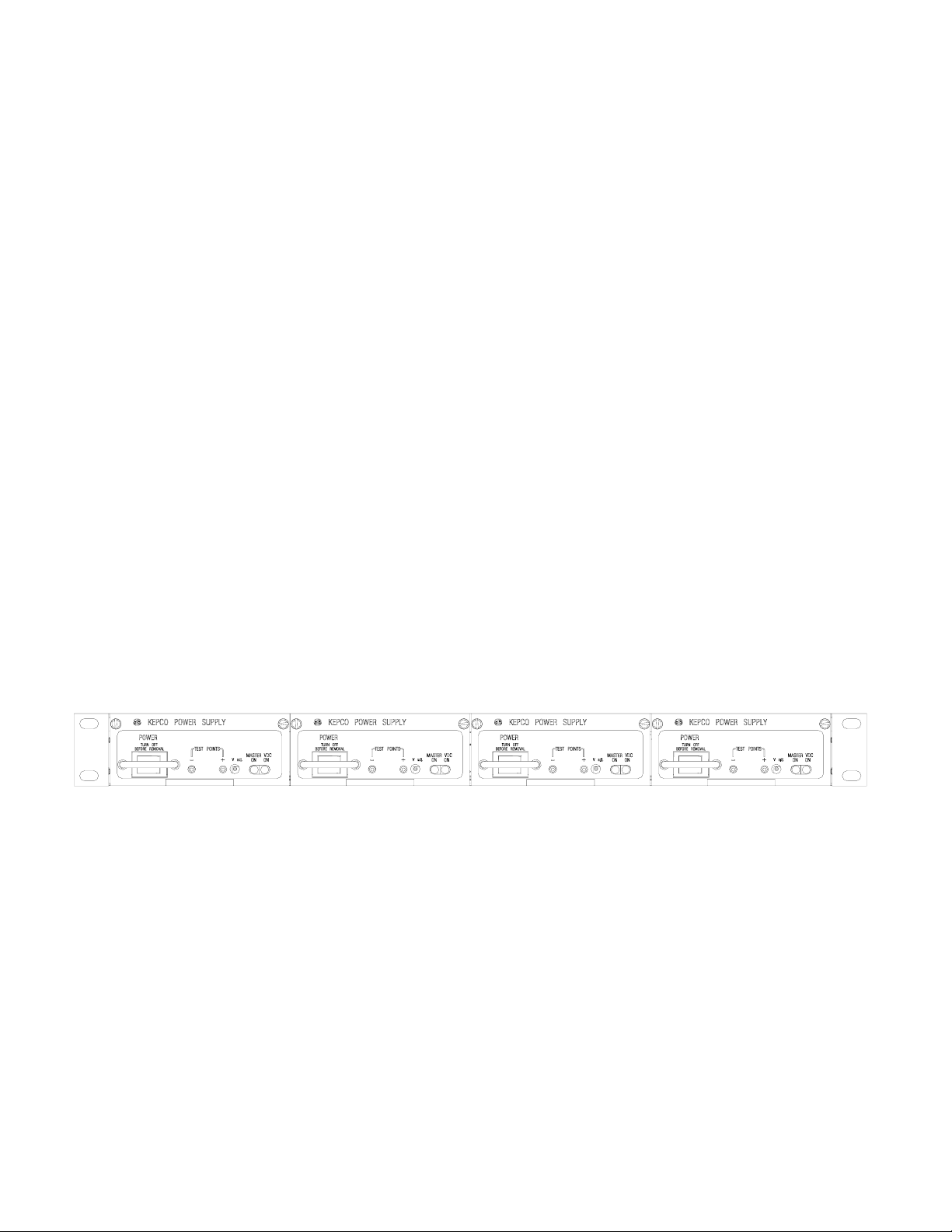
PS1 PS2
3042496
FIGURE 2. HSF -1UR MODELS INSTALLED IN RA 19-1U RACK ADAPTER
PS3
PS4
KEPCO, INC. 131-38 SANFORD AVENUE FLUSHING, NY. 11355 U.S.A. TEL (718) 461-7000 FAX (718) 767-1102
http://www.kepcopower.com email: hq@kepcopower.com
2 228-1675 REV 1 061510
 Loading...