

Page 1
INSTRUCTION MANUAL
KEPCO
An ISO 9001 Company.
KIT
DIN FAW
-50P
DIN-RAIL MOUNTING KIT
FOR SERIES FAW 50W
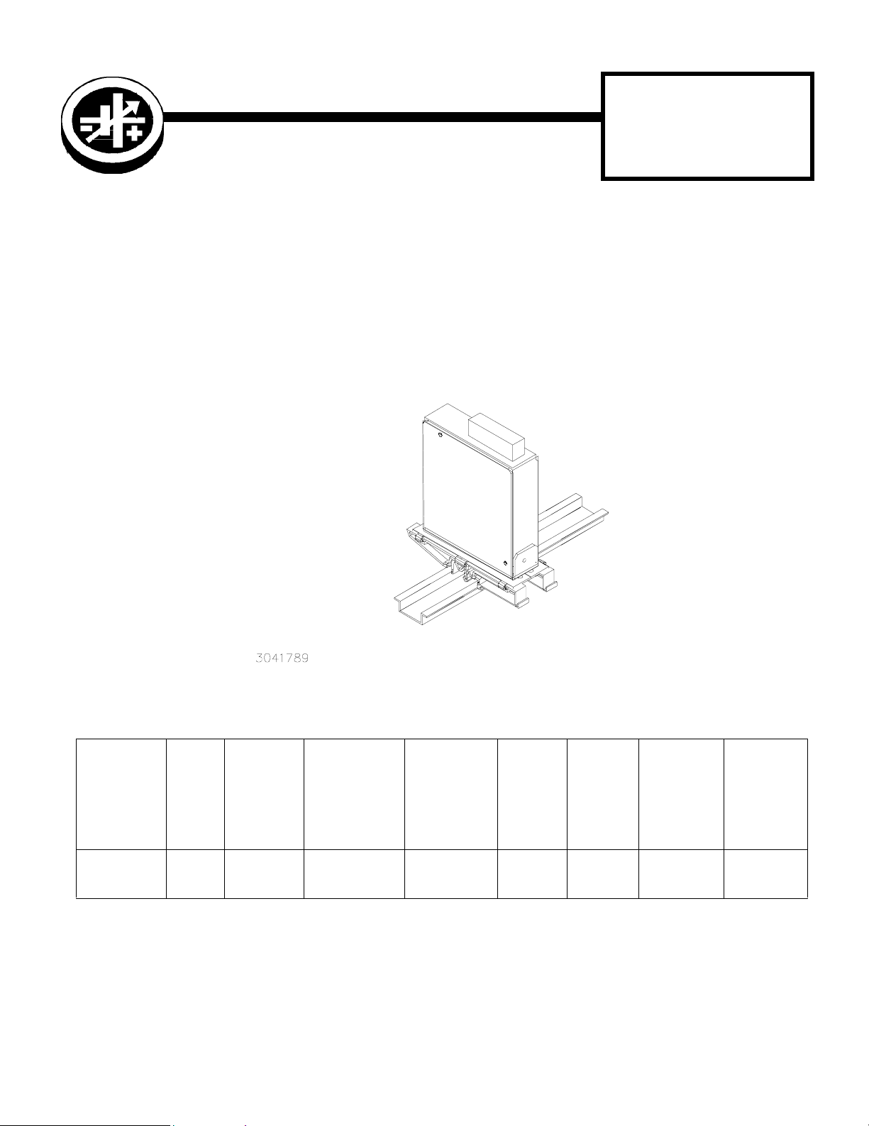
DESCRIPTION. Kepco KIT, Model DIN FAW-50P contains a cover, a mounting bracket with left and right preassem-
bled mounting clips and associated hardware used to install FAW Series power supplies on a DIN rail. The -50 suffix is
for the 50 Watt Series. The “P” suffix is for mounting the power supply perpendicular to the DIN rail as shown in Figure
1. Outline Dimensions are shown in Figure 5
FIGURE 1. P SUFFIX ORIENTATION
TABLE 1. COMPONENTS SUPPLIED
SCREW
KIT
MODEL NO.
DIN FAW-50P CA 26 128-1951
KEPCO, INC. " 131-38 SANFORD AVENUE " FLUSHING, NY. 11352 U.S.A. " TEL (718) 461-7000 "
©1998, KEPCO, INC
Data subject to change without notice 228-1322
COVER
PART
NO.
MOUNTING
BRACKET
PAR T N O .
http://www.kepcopower.com " email: hq@kepcopower.com
(QTY 3)
(Power Supply
To Mounting
Bracket)
PART NO.
101-0092
(4-40 X 5/16
BHPH)
WAS HE R
(QTY 3)
(Power Sup-
ply To Mount-
ing Bracket)
PART NO.
103-0014
(NO. 4, INT.
TOOTH)
CLIP
(QTY 2)
PART
NO.
108-0362 128-1938
CLIP
PLATE
(QTY 2)
PART NO.
SCREW
Thread-form
(QTY 4)
(Clip To
Mounting
Bracket)
PAR T N O .
101-0443
(4-40 X 1/4
BHPH)
FAX (718) 767-1102
WASHER
(QTY 4)
(Clip To
Mounting
Bracket)
PART NO.
103-0014
(NO. 4, INT.
TOOTH)
1
Page 2
INSTALLATION
1. INSTALL COVER. Attach the cover to the power supply per instruction manual supplied with the cover.
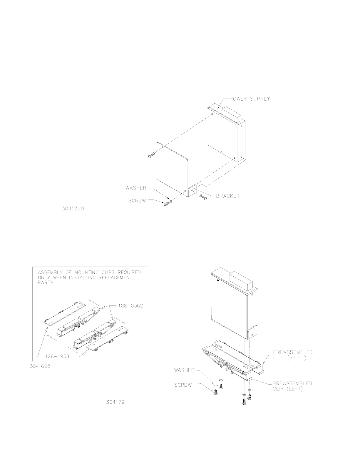
2. INSTALL MOUNTING BRACKET. Attach the mounting bracket to the power supply using the hardware
supplied (see Figure 2).
FIGURE 2. INSTALLING MOUNTING BRACKET ON POWER SUPPLY
3. INSTALL CLIPS. Attach preassembled mounting clips into the mounting bracket holes using hardware
supplied (see Figure 3).
FIGURE 3. INSTALLING CLIPS ON MOUNTING BRACKET
KEPCO, INC. " 131-38 SANFORD AVENUE " FLUSHING, NY. 11352 U.S.A. " TEL (718) 461-7000 "
2
http://www.kepcopower.com " email: hq@kepcopower.com
228-1322 061901
FAX (718) 767-1102
Page 3
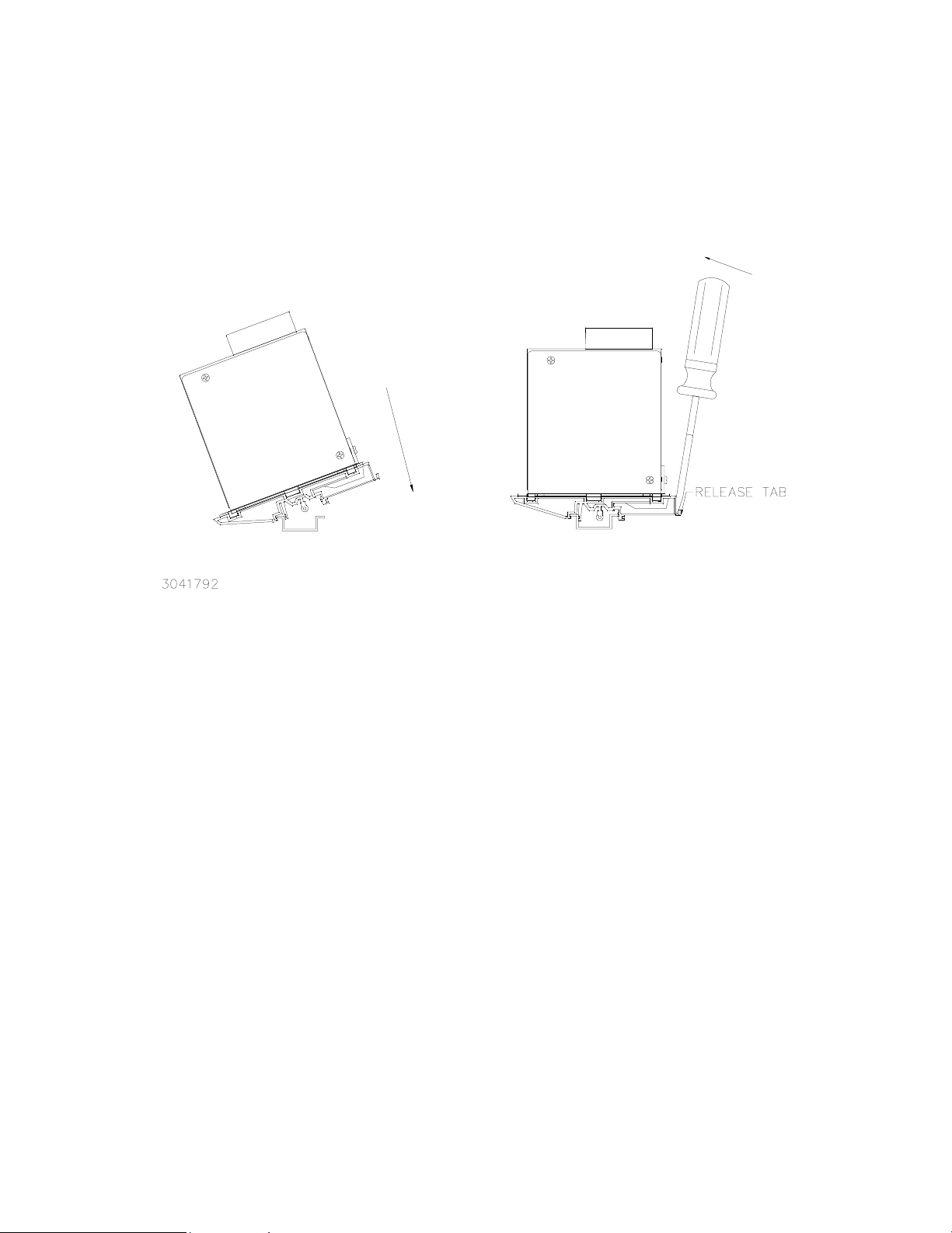
4. INSTALL POWER SUPPLY ON DIN RAIL. To mount the power supply on the rail insert one end of both
mounting clips under one edge of the rail, then snap the other end of the two clips into place (see Figure 4A).
INSTALLATION
A
B
REMOVAL
FIGURE 4. INSTALLATION AND REMOVAL OF POWER SUPPLY FROM DIN RAIL
REMOVING POWER SUPPLY FROM DIN RAIL. While grasping the power supply with one hand, Insert a screwdriver
into the access holes provided and apply leverage towards the left as shown in Figure 4B to disengage each clip from
the rail. Where mounting clips are close together, it may be necessary to apply leverage with two screwdrivers simultaneously.
KEPCO, INC. " 131-38 SANFORD AVENUE " FLUSHING, NY. 11352 U.S.A. " TEL (718) 461-7000 "
http://www.kepcopower.com " email: hq@kepcopower.com
061901 228-1322
FAX (718) 767-1102
3
Page 4
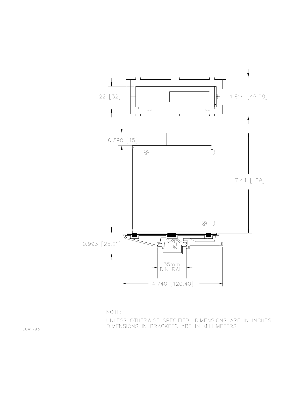
FIGURE 5. FAW 15W/25W POWER SUPPLY WITH KIT INSTALLED, OUTLINE DIMENSIONS
KEPCO, INC. " 131-38 SANFORD AVENUE " FLUSHING, NY. 11352 U.S.A. " TEL (718) 461-7000 "
4
http://www.kepcopower.com " email: hq@kepcopower.com
228-1322 061901
FAX (718) 767-1102
 Loading...