

Page 1

INSTRUCTION MANUAL
KEPCO
An ISO 9001 Company.
FAW
KEPCO SINGLE OUTPUT 15 WATT
HIGH FREQUENCY SWITCHING POWER SUPPLIES
I — INTRODUCTION
The Kepco FAW 15 Watt Series low profile high frequency switching power supplies employ flyback conversion and operate with a 70% efficiency with
either a-c or d-c inpu t. A thermistor soft-start circu it limits start-up surge. Surface m ount technolog y permits efficient c omponent layo ut for minimum
mounting space. Four models may be selected for outputs of 5, 12, 15 or 24V. “POWER OK” logic and a green “POWER OK” light are provided. A stee l
cover (Model CA 24) is available as an option. Output voltage may be adjusted with a trimmer accessible near the input-output terminal strip. When the
input is cut off, the output is maintained for 15 milliseconds minimum. EMI filtering meets FCC Class B rating and VDE 0871 Class B ratin g. This page
contains specificatio ns for each model of the FAW 15 Watt Series. Environmental specifications f or each model are the same.
II — SPECIFICATIONS
The following specificat ions apply to FAW 15 Watt Series models. Other models are also avai lable; consult your Kepco representative for their specifications.
TABLE 1. OUTPUT RATINGS AND SPECIFICATIONS, FAW 15W SERIES
MODEL FAW 5-3K FAW 12-1.3K FAW 15-1K FAW 24-0.7K
OUTPUT VOLTS, d-c (NOMINAL)
ADJUSTMENT RANGE
OUTPUT CURRENT (NOMINAL)
OUTPUT POWER (MAXIMUM)
source (typ)
RIPPLE
AND
NOISE
(mV p-p)
0-50°C
10-100% LOAD
OVERVOLTAGE SETTING 25°C, NOM. INPUT
OVERCURRENT SETTING 25°C, NOM. INPUT
source (max)
switching (typ)
switching (max)
spike noise (d-c—50MHz)
5V 12V 15V 24V
4.2-5.5V 10.8-13.2V 13.5-16.5V 21.6-26.4V
3.0A 1.3A 1.0A 0.7A
15.0W 15.6W 15.0W 16.8W
10 20 20 30
30 50 50 50
15 10 10 20
30 30 30 50
120 190 220 310
6.0-6.9V 13.7-15.7V 17.0-19.0V 27.0-30.5V
3.3-5.5A 1.4-2.5A 1.1-2.0A 0.8-1.4A
INPUT:
Voltage: 120V a-c/240V a-c nominal; Range 85- 264V a-c; 110-370V d-c.
Frequency: Nominal 5 0- 60 H z; Range 47-440Hz (at 440Hz leakage current exceeds UL/VDE safety spec .li m i t).
Current (nominal output at rated load): @120V a-c rms: 0.3A typ., 0.4A m ax; @240V a-c rms: 0.2A typ., 0. 3A m ax .
Initial Turn-on Surge: (one-half of first input c ycle): @120V a-c rms, 22A max., @240V a-c rms, 34A max.
STABILIZATION:
Source Effect: Range 85-132V a- c or 170 -2 64V a-c, 1.0% typ.; 2.0% max.
Load Effect: Range 10%-10 0% lo ad , 1.0% typ.; 2.0% max.
Temperature Effect: Range 0
Combined Effect: 2.6% typ.; 4.0% max. (includes source, load, and temperature effects).
Drift: 0.1% typ.; 0.5% max. (1/2 hr-8 hr at 25
RECOVERY CHARACTERISTICS:
1% of the original setting in <2 ms
+
START-UP TIME:
HOLD-UP TIME:
DIELECTRIC STRENGTH:
Between input and output: 2KV a- c for one minute.
Between input and output with Y- capacitor removed: 3.75KV a- c f or one m i nute.
Between input and case (gr ound): 2KV a-c for one minute.
INSULATION RESISTANCE:
100 Megohms min. (500V d-c).
©1996, KEPCO, INC
Data subject to change without notice
500 ms. maximum.
15 ms. min (100V a-c), 20 ms. typ. (120V a-c).
KEPCO, INC. !"! 131-38 SANFORD AVENUE !" FLUSHING, NY. 11352 U.S.A.!!" TEL (718) 461-7000!!"! FAX (718) 767-1102!!
o
to 50oC, 1.0% typ.; 2.0% max.
o
C).
A step load change from 50% to 100% produces less t han +4% output excur sion. Recovery occur s to within
(tr or tf equal to or greater than 50µsec at load change).
Between input and grou nd, out put and ground, input and ou t put ;
http://www.kepcopower.com "! email: hq@kepcopower.com
228-1156
1
Page 2
LEAKAGE CURRENT
(UL method, 120V a-c, 50 -6 0H z): 0.5 mA maximum.
(VDE method, 240V a-c): 0.75 mA maximum.
SAFETY:
“POWER OK” SIGNAL OUTPUT:
CONNECTOR TYPES:
TC100F-2.
CONNECTOR KIT:
Model Kit P/N 518-0029 . The connector is provided wi th 1 me te r length leads for trimming to de si re d l engths.
EMI:
VIBRATION:
SHOCK:
OPERATING TEMPERATURE:
STORAGE TEMPERATURE:
OPERATING AND STORAGE RELATIVE HUMIDITY:
FUSE:
WARRANTY:
UL 478 recognized; CSA 14 02B certified, VDE 0806, IEC 380 app ro ved by TÜV Rheinland
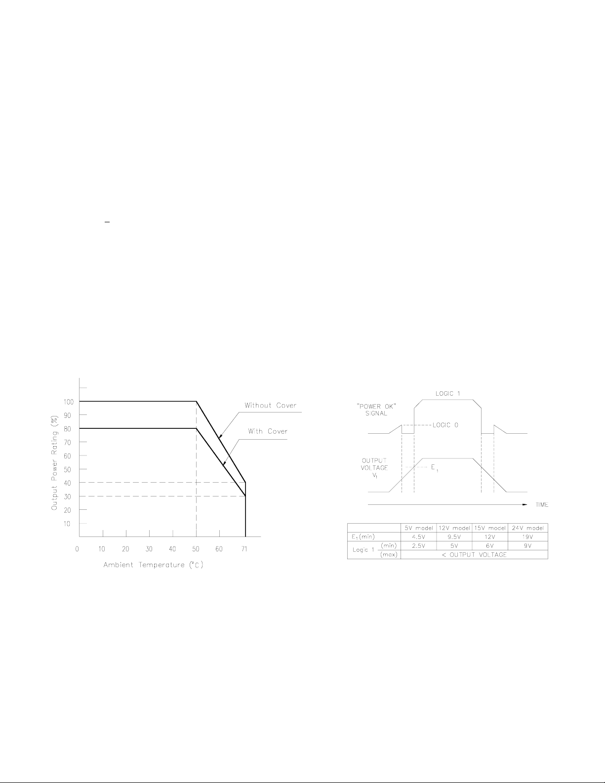
The unit supplies a “POWER OK” logic 1 signal at CP51 (see Figure 2).
Refer to the Mechanical Outline Drawing. The mating connector for CP51 is a Panduit, P/N CT10F22-2: Cover, P/N
Kepco furnishes an option al connector kit with the specified conn ector listed above. The kit may be order ed under Kepco
Designed to meet FCC Class B (100-120V a-c) and VDE 0871 Class B (220-240V a-c).
5-10 Hz, 10 mm amplitude.
10-55 Hz, 2g accelera tion .
Acceleration: 20g
Duration: 11ms +
(non-operating, one hour on each one of the three ax es) :
(non-operating, one- hal f sinusoidal pulse, three shock s t o each axis):
5ms
See Figure 1.
-40oC to +75oC.
up to 95% (wet bulb temp. <35oC non-condensing).
Quick acting 2A, 250V; (5.2 x 20mm), San-O P/N MT4 2A; Kepco P/N 541-0109.
1 year.
FIGURE 1. OUTPUT POWER RATING VS. AMBIENT TEMPERATURE FIGURE 2. “POWER OK” SIGNAL RELATED TO OUTPUT
KEPCO, INC. !"! 131-38 SANFORD AVENUE !" FLUSHING, NY. 11352 U.S.A.!!" TEL (718) 461-7000!!"
2
3040229/1161
http://www.kepcopower.com "! email: hq@kepcopower.com
228-1156 062599
!
FAX (718) 767-1102!!
Page 3
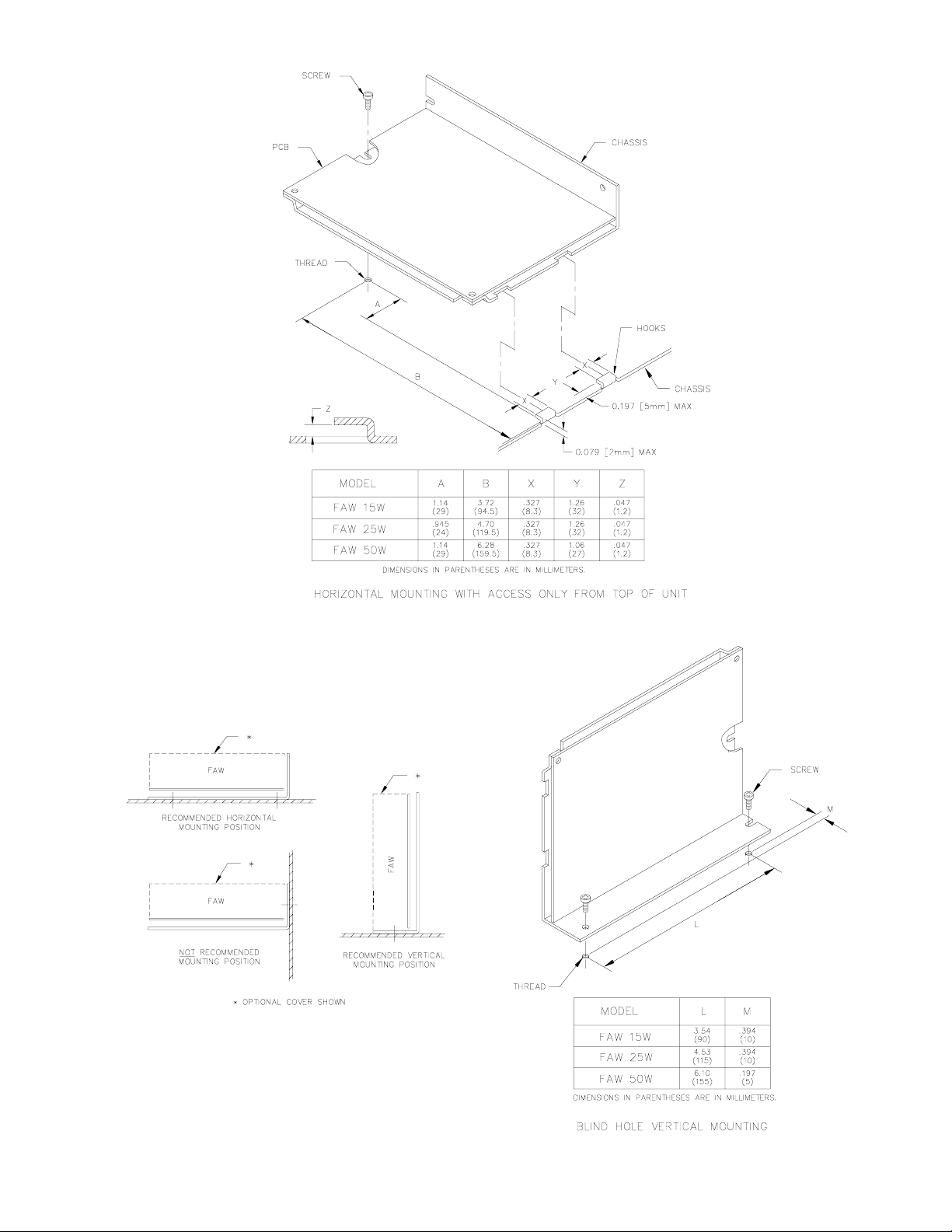
POSSIBLE MOUNTING CHOICES
KEPCO, INC. !"! 131-38 SANF OR D AVENUE !" FLUSHING, NY. 11352 U.S.A.!!" TEL (718) 461-7000!!"! FAX (718) 767-1102!
062599 228-1156
30400550
http://www.kepcopower.com "
!
email: hq@kepcopower.com
3
Page 4
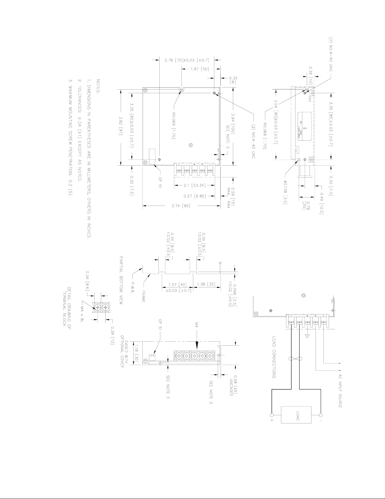
MECHANICAL OUTLINE DRAWING
KEPCO, INC. !"! 131-38 SANF OR D AVENUE !" FLUSHING, NY. 11352 U.S.A.!!" TEL (718) 461-7000!!"! FAX (718) 767-1102!
4
CM17960
http://www.kepcopower.com "! email: hq@kepcopower.com
228-1156 062599
 Loading...