

Page 1
INSTRUCTION MANUAL
KEPCO
An ISO 9001 Company.
FAW
KEPCO SINGLE OUTPUT 150 WATT
HIGH FREQUENCY SWITCHING POWER SUPPLIES
I — INTRODUCTION
The Kepco FAW 150 Watt Series low profile h igh frequen cy switchin g power su pplies emp loy forward conversion and operat e with a 78% efficiency
with either a-c or d-c inpu t. A res istor a nd thyrist or so ft-star t circu it limits s tart- up sur ge. Surf ace m ount te chnol ogy pe rmit s efficient com pon ent l ayout
for minimum mounting space. Six models may be selected for outputs of 5, 12, 15, 24, 28, or 48V. “POWER OK” logic and a green “POWER OK” LED
are provided. A ste el cover ( Model CA 28) is av ailable as an opt ion. Outp ut voltag e may b e adjuste d with a trimmer accessibl e nea r the inpu t-output
terminal strip (R65, see Figure 4, View “A”). W hen the input is cut off, the output is maintained for 15 milliseconds minimum. If the pow er supply shu ts
down, it is then n ecess ary t o wai t 90 seco nd s minim um (120 V a-c inpu t) o r 120 seco nds mini mum (240V a- c in put) be fore reco nnect ing the a-c inp ut
power to turn on th e u nit ag ain. EMI filterin g m eets FC C C lass B (10 0 to120 Volts) rating and VD E 087 1 C lass B (220 to 240 Volts) rating. This page
contains specificatio ns f or eac h model of the FAW 150 Watt Series. Environmental specifications fo r ea ch model are the same.
II — SPECIFICATIONS
The following specifications apply to FAW 150 Watt Series models. Other FA W Series models are also available; consult your Kepco representative for
their specifications.
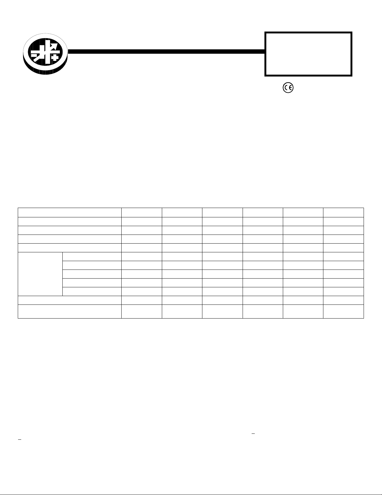
TABLE 1. OUTPUT RATINGS AND SPECIFICATIONS, FAW 150W SERIES
MODEL FAW 5-30K FAW 12-12K FAW 15-10K FAW 24-6K FAW28-5K FAW 48-2.8K
OUTPUT VOLTS, d-c (NOMINAL) 5V 12V 15V 24V 28V 48V
ADJUSTMENT RANGE 4.5 - 5.5V 10.8 - 13.2V 13.5 - 16.5V 21.6 - 26.4V 25.2 - 30.8V 38.4 - 52.8V
OUTPUT CURRENT (NOMINAL)
OUTPUT PO W ER (MAXIMU M )
RIPPLE
AND
NOISE
(mV p-p)
0-50°C
10-100% LOAD
OVERVOLTAGE SETTING (25 °C, NOM. INPUT) 6.0-6.9V 13.7-15.7V 17.0-19.0V 27.0-30.5V 32.0-35.0 53.5-60.0
OVERCURRENT SETTING (25°C, NOM. INPUT)
Rectangular type characteristic
(1) Derates same as Ouptut Power.
(2) See power derating curve, Figure 1.
source (max) 20 30 40 40 40 40
switching (typ)303540506080
switching (max) 60 70 80 110 140 220
spike noise (d-c—50MHz) <120 <190 <220 <310 <330 <530
(1 )
(2 )
source (typ)101515152020
30A 12A 10A 6A 5A 2.8A
150W 144W 150W 144W 140W 134.4W
32.0 - 36.0A 13.0 - 15.0A 11.0 - 13.0A 6.3 - 7.5A 5.3 - 6.1A 3.0 - 3.5A
INPUT:
Voltage: 120V a-c/240V a-c nominal; Range 85-264V a-c; 105-370V d-c (po larity insensitive).
Frequency: Nomina l 50- 60 H z; Range 47-440Hz (at 440Hz leakage current exc eeds UL/VDE safety leakage standards).
Current (nominal output at rated load): @120V a-c rms: 3.0A typ., 3.5A m ax; @240V a-c rms: 1.5A typ., 2. 0A m ax .
Initial Turn-on Surge: (one-half of first inpu t c ycle): @120V a-c rms, 25A max.; @2 40V a-c rms, 50A max. When the a- c in put power is removed,
the soft start circuit requ ires 30 seconds recovery tim e before the a-c input power is rec onnected.
Brownout Voltage: 80V a-c, 97V d-c.
Switching Frequency: 120KHz typical, nominal load.
STABILIZATION:
Source Effect: Range 85-132V a- c or 170 -2 64V a-c, 1.0% typ.; 2.0% max.
Load Effect: Range 10%-10 0% lo ad , 1.0% typ.; 2.0% max.
Temperature Effect: Range 0
Combined Effect: 2.0% typ.; 4.0% max. (includes source, load, and temperature effects).
Time Effect: 0.1% typ.; 0.5% max. (1/2 hr-8 hr at 25
RECOVERY CHARACTERISTICS:
1% of the original setting in <1 ms
+
START-UP TIME:
HOLD-UP TIME:
©1996, KEPCO, INC
Data subject to change without notice
200 ms. maximum.
20 ms. typ. (120V a-c), 15 ms. min (100V a-c).
KEPCO, INC. !"! 131-38 SANFORD AVENUE !" FLUSHING, NY. 11352 U.S.A.!!" TEL (718) 461-7000!!"! FAX (718) 767-1102!!
o
to 50oC, 1.0% typ.; 2.0% max.
o
C).
A step load change from 50% to 100% produces less t han +4% output excur sion. Recovery occur s to within
(tr or tf equal to or greater than 50µsec at load change).
http://www.kepcopower.com "! email: hq@kepcopower.com
228-1159
1
Page 2

DIELECTRIC STRENGTH:
Between input and output: 2KV a- c for one minute.
Between input and output with Y- capacitor removed: 3.0K V a-c for one minute.
Between input and case (gr ound): 2.0KV a-c for one minute .
INSULATION RESISTANCE:
100 Megohms min. (500V d-c).
Between input and grou nd, out put and ground, input and ou t put ;
LEAKAGE CURRENT
(UL method, 120V a-c, 50 -6 0H z, single terminal connec tion): 0.5 mA maximum.
(VDE method, 240V a-c, two terminal connection): 0.75 mA maximum.
SAFETY:
22.2 No. 234 (M90) Level 3 ( FAW 48-2.8K Level 1 Certified [ambi ent tem pera ture 50° C maxi mum] , IEC 95 0 Appr oved by TÜV Rhe inlan d (based
on EN 60950/09.87, ambient temperature 50° C max.) - cover removed.
(+) SENSE, (–) SENSE:
be connected to the ir respec tive (+) and (–) output ter minals, e ither at the load or at the Power Su pply out put termi nals. Th e connec tion en sures
the most accurate error tracking. Error compensation in the connecting wires is up to 0.25 Volts for the FAW 5-30K model, and up to 0.4 Volts for
all other models.
“POWER OK” SIGNAL OUTPUT:
CONNECTOR TYPES:
TC100F-2.
CONNECTOR KIT:
Model Kit P/N 518-0029 . The connector is provided wi th 1 me te r length leads for trimming to de si re d l engths.
EMI:
VIBRATION:
SHOCK:
OPERATING TEMPERATURE:
STORAGE TEMPERATURE:
OPERATING AND STORAGE RELATIVE HUMIDITY:
MOUNTING SCREW:
MAXIMUM SCREW PENETRATION:
WEIGHT:
DIMENSIONS:
CASE DIMENSIONS:
FRAME MATERIAL:
FUSE:
WARRANTY:
UL 1950 recognized (amb ient tem peratu re 40° C maximu m); C SA E.B. 140 2C Le vel 3 Ce rtified (FAW 48-2.8K Level 1 Certified); CSA
These terminals are provided to compensate for voltage drops in the load connecting wires. The Sense terminals must
The unit supplies a “POWER O K ” logi c 1 si gn al at CP 51 ( see Fi gur e 2 and Figure 4, View “A”).
Refer to the Mechanical Outline Drawing. The mating connector for CP51 is a Panduit, P/N CT10F22-2: Cover, P/N
Kepco furnishes an option al connector kit with the specified conn ector listed above. The kit may be order ed under Kepco
Designed to meet FCC Class B (100-120V a-c) and VDE 0871 Class B (220-240V a-c).
5-10 Hz, 10 mm amplitude.
10-55 Hz, 2g accelera tion .
Acceleration: 20g
Duration: 11ms +
(non-operating, one hour on each one of the three ax es) :
(non-operating, one- hal f sinusoidal pulse, three shock s t o each axis):
5ms
0 - 71° C (see Figure 1).
–40oC to +75oC.
up to 95% (wet bulb temp. <35oC non-condensing).
No. 4-40 UNC Thread (see Figure 4)
0.197 in. (5mm) max.
2.65 lbs. (1.2Kg max.), 4.41 lbs. (2.0 Kg max. with cover).
3.74 in. (95mm) H x 2.01 in. (51mm) W x 7.87 in. (200 mm) L
3.74 in. (95mm) H x 2.09 in. (53mm) W x 7.87 in. (200 mm) L
Aluminum
Quick acting 6.3A, 250V; (5.2 x 20mm), San- O P/ N EQ 6. 3A; Kepco P/N 541-0113.
1 year.
KEPCO, INC. !"! 131-38 SANFORD AVENUE !" FLUSHING, NY. 11352 U.S.A.!!" TEL (718) 461-7000!!"
2
http://www.kepcopower.com "! email: hq@kepcopower.com
228-1159 062599
!
FAX (718) 767-1102!!
Page 3

FIGURE 1. % OUTPUT POWER RATING VS. FIGURE 2. “POWER OK” SIGNAL RELATED TO OUTPUT
AMBIENT TEMPERATURE
FIGURE 3. LOAD CONNECTIONS WITH ERROR SENSING
KEPCO, INC. !"! 131-38 SANF OR D AVENUE !" FLUSHING, NY. 11352 U.S.A.!!" TEL (718) 461-7000!!"! FAX (718) 767-1102!
062599 228-1159
3040229/0228/0375
http://www.kepcopower.com "
!
email: hq@kepcopower.com
3
Page 4

FIGURE 4. MECHANICAL OUTLINE DRAWING
KEPCO, INC. !"! 131-38 SANFORD AVENUE !" FLUSHING, NY. 11352 U.S.A.!!" TEL (718) 461-7000!!"
4
CM18672
http://www.kepcopower.com "! email: hq@kepcopower.com
228-1159 062599
!
FAX (718) 767-1102!!
 Loading...