

Page 1
QUICK START GUIDE
KEPCO
An ISO 9001 Company.
BIPOLAR OPERATIONAL
POWER SUPPLY
I — INTRODUCTION
1.1. SCOPE OF MANUAL. This Quick Start Guide
covers simple installation and local operation of the Kepco
100W, 200W and 400W Series of BOP Bipolar Operational
Power Supplies. Full specifications, features and instructions are found in the BOP Operator Manual that can be
downloaded free from the Kepco web site at:
www.kepcopower.com/support/opmanls.htm#bop-op
1.2. DESCRIPTION. Kepco’s BOP are linear stabilizers with two bipolar control channels (voltage or current mode), selectable and individually controllable either by front panel controls, or by remote signals. These two principal control channels are each protected by bipolar limit circuits. The positive and negative current or voltage limit points can be manually set or remotely programmed simultaneously or Individually. Automatic crossover between each principal control channel and the limit channels is provided. Only one principle channel (voltage or current) can control the output at any one time.
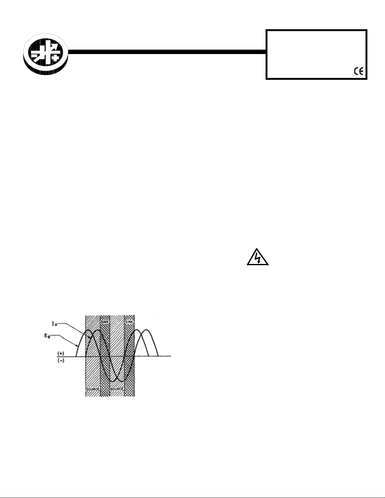
The BOP can act as either a source (output voltage is the
same direction as output current) or a sink (output voltage
is opposite that of output current). An example is shown in
Figure 1 where the BOP is programmed to deliver a sine
wave output and the load produces a phase shift between
the output voltage and current.
BOP
100W, 200W,
400W
1.3. OPTIONS. Standard models (M suffix) include analog voltage and current meters. Models with a D suffix include digital meters.
1.4. EQUIPMENT SUPPLIED.
• PC 15 connector (MUST be installed at rear panel
to enable local operation).
• 115V a-c Line Cord
1.5. ACCESSORIES (NOT SUPPLIED)
• Slides (Full rack only)
• Rack adapter RA 24 or RA 37 (mount 3/4 rack unit
in 19-inch rack)
II — SAFETY.
Exercise care in making all connections to and from the
BOP terminals.
WARNINGS
1. Remove a-c power from the BOP before making any
connections.
2. Wires and/or cables, connected from the BOP terminals
to external components or programming devices must
be properly insulated and securely terminated on both
sides to make accidental touch impossible. DO NOT
USE BANANA PLUGS WITH EXPOSED SCREWS OR
OTHER EXPOSED METAL PARTS AT THE FRONT
PANEL OUTPUT TERMINALS!
3. The BOP chassis and cover must be safety-grounded to
a reliable a-c source ground. A safety-ground may be
established by using a grounded a-c power outlet or, if
the latter is not available, by means of a separate wire,
from the provided GROUND terminal to a reliable a-c
source ground point.
FIGURE 1. SINK OPERATION PRODUCED BY LOAD
PHASE SHIFT
Units are shipped for 115V a-c operation (105V to 125V
a-c), 50 to 65Hz. For operation at 104V a-c, 208V a-c or
230V a-c refer to the full Operator manual (PAR 1.1).
KEPCO, INC. " 131-38 SANFORD AVENUE " FLUSHING, NY. 11355 U.S.A. " TEL (718) 461-7000 " FAX (718) 767-1102
http://www.kepcopower.com " email: hq@kepcopower.com
©2009, KEPCO, INC 1
Data subject to change without notice 228-1678
4. THE COMMON OUTPUT TERMINAL OF THE BOP
SHOULD BE GROUNDED. If for any reason, grounding
of the output is not possible, additional precautions must
be taken to make any access to the isolated output
impossible.
Page 2

III — INSTALLATION
3.1. UNPACKING. The power supply has been thor-
oughly inspected and tested prior to packing and is ready
for operation. After careful unpacking, inspect for shipping
damage before attempting to operate. Perform the Preliminary Checkout (PAR. 3.2). If any indication of damage is
found, file an immediate claim with the responsible transport service
3.2. PRELIMINARY CHECKOUT. A simple operating check after unpacking and before permanent installation, is advisable to ascertain whether the BOP has suffered damage in shipment.
1. Install PC15 (supplied) at rear panel. This is required
for local control of the unit.
2. Refer to Safety instructions (see Section IV) and connect unit to 115V a-c source; see Operator manual
(PAR 1.1) for different source voltage.
8. Turn the Current Control clockwise through its range,
while observing the front panel Ammeter. The BOP
output current should respond smoothly, from the maximum negative output current, through zero, to the
maximum positive output current of the BOP.
9. Set A-C POWER circuit breaker/switch OFF. Remove
the short circuit from the output terminals. This concludes the preliminary check-out of the BOP.
3.3. INSTALLING THE POWER SUPPLY.
3/4 RACK MODELS. These models are shipped with four
plastic feet installed for benchtop operation. The feet must
be removed for rack mounting. Kepco’s RA 24 or RA 37
can be used to install these models in a standard 19-inch
rack (installation instructions supplied with rack adapter).
Four plastic mounting inserts on the bottom of the chassis
can be used to mount the unit on any flat surface.
3. Set the BOP front panel controls as follows
a. Voltage/Current MODE select switch set to VOLT-
AGE.
b. Voltage Control ON/OFF switch to ON, Voltage
Control to extreme counterclockwise position.
c. A-C POWER circuit breaker/switch to ON.
d. The E
Mode indicator will be “on.”
O
4. Turn the Voltage Control clockwise through its range,
while observing the front panel Voltmeter. The BOP
output voltage should respond smoothly, from the maximum negative output voltage, through zero, to the
maximum positive output voltage of the BOP.
5. Set A-C POWER circuit breaker/switch OFF.
6. Connect a short circuit between the OUTPUT and
COMMON front panel output terminals.
7. Set the BOP front panel controls as follows:
a. Voltage/Current MODE select switch set to CUR-
RENT.
b. Current Control ON/OFF switch to ON and Current
Control to its maximum counterclockwise position.
c. A-C POWER circuit breaker/switch to ON.
d. The I
Mode indicator will be “on.”
O
FULL RACK MODELS. These models are shipped with
fixed angle brackets and chassis slide support bars
installed and are ready for mounting in a 19-inch rack.
3.4. CONNECTIONS. Connections can be made using either the front or rear panel terminations, but not both.
LOAD CONNECTIONS. Connect the load between OUTPUT and COMMON terminals. Connections may be made
at either the front or rear panel. Sense connections are
required, either local or remote, must be used; otherwise the unit will not operate.
SENSE CONNECTIONS. For local sensing The OUTPUT
and COMMON terminals are connected to the adjacent
SENSE terminals. The unit is shipped with local sensing
links in place at the rear panel. If load connections are
made at the front panel, remove the installed links from
the rear panel. At the front panel install jumpers between
COMMON and the adjacent SENSE terminal and
between OUTPUT and the adjacent SENSE terminal. If
desired, a link between terminals 5 and 6 at the rear panel
may be installed to enable the Grounding Network.
Remote sensing (connecting the corresponding SENSE
terminals to the OUTPUT and COMMON terminations at
the load instead of at the BOP) can compensate for load
wire losses up to 0.5V per wire. Remote sensing is recommended for minimum load effect for a remote load. Use
twisted pairs: #22 AWG for output sense lines and wires
rated for the nominal output current of the power supply
for power leads. See full Operator Manual (see PAR. 1.1)
for remote sensing requirements.
KEPCO, INC. " 131-38 SANFORD AVENUE " FLUSHING, NY. 11355 U.S.A. " TEL (718) 461-7000 " FAX (718) 767-1102
http://www.kepcopower.com " email: hq@kepcopower.com
2 228-1678 071609
Page 3
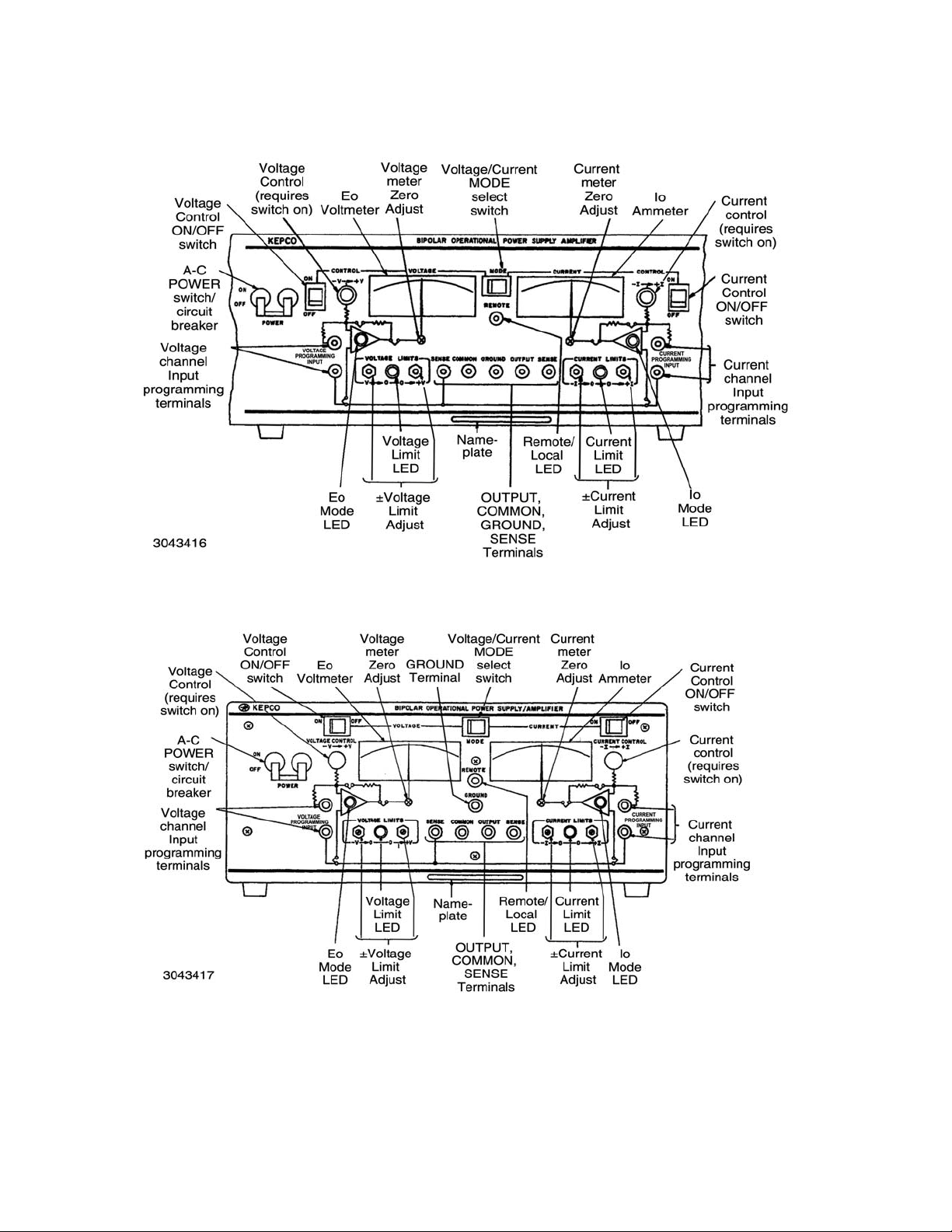
FIGURE 2. BOP FULL RACK, FRONT PANEL CONTROLS, INDICATORS AND TERMINATIONS
FIGURE 3. BOP 3/4 RACK, FRONT PANEL CONTROLS, INDICATORS AND TERMINATIONS
KEPCO, INC. " 131-38 SANFORD AVENUE " FLUSHING, NY. 11355 U.S.A. " TEL (718) 461-7000 " FAX (718) 767-1102
071609 228-1678 3
http://www.kepcopower.com " email: hq@kepcopower.com
Page 4

INPUT A-C CONNECTIONS. Install the line cord (supplied) at the rear panel and connect to 115V a-c, 60Hz
(105V to 125V a-c, 50 to 65Hz) mains. Refer to the full
Operator Manual (see PAR. 1.1). For operation at 104V ac, 208V a-c or 230V a-c refer to the full Operator manual
(PAR 1.1).
avoid common mode current from affecting the BOP output, the system (including the programming device, if
used, load, and BOP) must have a single connection to
ground (earth ground). The d-c ground wire must be rated
for the nominal output current of the BOP (e.g, for BOP
20-10M, use rating of 10A).
A-C GROUND. The 3-wire line cord with 3-prong safety
plug (supplied), in combination with a properly grounded
a-c power outlet, automatically grounds the BOP case. If
an adapter for a non-grounded outlet is used, the case
must be grounded separately using a separate GROUND
terminal at either the front or rear panel. The ground wire
must be rated for at least the BOP input current (as noted
on nameplate at rear of unit).
D-C SIGNAL GROUND. Specified ripple and noise figures for BOP power supplies are valid only with the COMMON side of the output load circuit returned to a ground
point. The BOP circuits, including output and programming terminals, have no d-c connection to the chassis.
The COMMON terminal of the BOP can be “floated” up to
500 volts (d-c or peak) off a-c ground. The common mode
current (leakage from output to ground) Is less than 50
µA
(rms) or 5 mA (p-p) at 115V a-c power input, 60 Hz. To
Multiple signal grounds in the system may cause “groundloop” problems, since noise signals develop across the
impedances between the multiple ground points. The
exact physical location of the “best” single ground point
must be carefully selected for minimum ripple/noise output.
3.5. COOLING. The components in the BOP power supply rely on forced air cooling. SIDE PANEL OPENINGS AND THE TOP OF THE CASE MUST BE KEPT CLEAR FROM ALL OBSTRUCTIONS TO ENSURE AIR CIRCULATION. Periodic cleaning of the interior of the power supply is recommended. If the BOP is rackmounted or installed into confined spaces, care must be taken that the ambient temperature (the temperature immediately surrounding the power supply) does not rise above 55°C (~157°F).
FIGURE 4. BOP REAR PANEL TERMINATIONS
KEPCO, INC. " 131-38 SANFORD AVENUE " FLUSHING, NY. 11355 U.S.A. " TEL (718) 461-7000 " FAX (718) 767-1102
http://www.kepcopower.com " email: hq@kepcopower.com
4 228-1678 071609
Page 5

IV — OPERATION
Turn the unit on using the front panel POWER switch/circuit
breaker (see Figure 2 or 3). CAUTION: DO NOT repeat-
edly toggle the POWER on/off switch as this may
cause unit to fault. If actuator does not lock when
released, wait a few seconds before trying again. The circuit breaker is "trip-free;” if overload exists, contacts cannot
be held closed by actuator.
NOTE: PC 15 rear programming connector must be
installed to enable local control of the unit.
4. Set the CURRENT CONTROL switch to OFF. Set the
MODE switch to VOLTAGE and the VOLTAGE CONTROL switch to ON, then set BOP POWER a-c circuit
breaker/switch to ON.
5. Adjust the ± I CURRENT LIMIT potentiometers for both
polarities as required, monitoring the CURRENT meter
for the correct limiting value. Proceed as follows:
a. Turn VOLTAGE CONTROL fully counterclockwise.
Use a screwdriver to adjust the – I CURRENT
LIMIT potentiometer as desired.
4.1. VOLTAGE MODE OPERATION WITH CURRENT LIMITING. The BOP may be used as a stabi-
lized (d-c) source of positive or negative voltage with output
current limiting (for either polarity) when pre-selected for
the application at hand. Always monitor the front panel
meters while adjusting output voltage/current.
1. Determine the output voltage and current requirements
of your load. Disconnect the load and set the BOP
MODE switch to CURRENT and the CURRENT CONTROL switch to ON.
2. Voltage limits are recommended to be greater than the
maximum voltage required for the load by 10% of the
rated voltage of the unit (e.g., for a 72V BOP and a load
that requires 30V, set voltage limits to ±37.2V).
If specific ± voltage limits are not needed, use a screwdriver to adjust the + V VOLTAGE LIMIT potentiometer
to full clockwise position and - V VOLTAGE LIMIT
potentiometer to full counterclockwise position.
If specific ± voltage limits are needed, proceed as follows.
a. Turn CURRENT CONTROL fully counterclockwise.
Use a screwdriver to adjust the – V VOLTAGE
LIMIT potentiometer as desired (recommended to
be 10% greater than the maximum negative voltage
required for the load), monitoring the VOLTAGE
meter for the correct limiting value.
b. Turn CURRENT CONTROL fully clockwise. Use a
screwdriver to adjust the + V VOLTAGE LIMIT
potentiometer as desired, monitoring the VOLTAGE
meter for the correct limiting value.
3. With the a-c POWER circuit breaker/switch set to OFF,
disconnect the load and connect a short circuit across
the OUTPUT and COMMON terminals.
b. Turn VOLTAGE CONTROL fully clockwise. Use a
screwdriver to adjust the + I CURRENT LIMIT
potentiometer as desired.
c. Set a-c POWER circuit breaker/switch to OFF, then
remove the short circuit from the output.
d. Set a-c POWER circuit breaker/switch to ON and
adjust the output voltage to zero using the VOLTAGE CONTROL.
e. Set a-c POWER circuit breaker/switch to OFF, then
connect the load to the BOP output.
6. Set a-c POWER switch/circuit breaker to ON, and
adjust the operating voltage by means of the VOLTAGE
CONTROL to the value required.
NOTE: If the output current exceeds the pre-adjusted value
at any time the VOLTAGE MODE indicator will go out and
the CURRENT LIMIT indicator will go on. After the cause of
the overcurrent is eliminated, the indicator lights will return
to their initial status.
4.2. CURRENT MODE OPERATION WITH VOLT-
AGE LIMITING. The BOP may be used as a stabilized
d-c source of positive or negative current, with output voltage limiting (for either polarity), pre-selected for the application at hand. Always monitor the front panel meters while
adjusting output voltage/current
1. Determine the output current and voltage requirement
of your load.
2. With the a-c POWER circuit breaker/switch set to OFF,
disconnect the load and connect a short circuit across
the OUTPUT and COMMON terminals.
3. Set the BOP MODE switch to VOLTAGE and the VOLTAGE CONTROL switch to ON, then set a-c POWER circuit breaker/switch to ON.
KEPCO, INC. " 131-38 SANFORD AVENUE " FLUSHING, NY. 11355 U.S.A. " TEL (718) 461-7000 " FAX (718) 767-1102
071609 228-1678 5
http://www.kepcopower.com " email: hq@kepcopower.com
Page 6

4. Current limits are recommended to be greater than the
maximum current required for the load by 10% of the
rated current of the unit (e.g., for a 6A BOP and a load
that requires 3A, set current limits to ±3.6A).
If specific ± current limits are not needed, use a screwdriver to adjust the + I CURRENT LIMIT potentiometer to full clockwise position and - I CURRENT LIMIT
potentiometer to full counterclockwise position.
If specific ±current limits are needed, proceed as follows:
a. Turn VOLTAGE CONTROL fully counterclockwise.
Use a screwdriver to adjust the – I CURRENT
LIMIT potentiometer as desired (recommended to
be 10% greater than the maximum negative current
required for the load), monitoring the CURRENT
meter for the correct limiting value.
b. Turn VOLTAGE CONTROL fully clockwise. Use a
screwdriver to adjust the + I CURRENT LIMIT
potentiometer as desired (recommended to be
10% greater than the maximum positive current
required for the load) monitoring the CURRENT
meter for the correct limiting value.
d. Set a-c POWER switch/circuit breaker to ON and
use the CURRENT CONTRol to adjust the output
current to zero.
e. Set a-c POWER switch/circuit breaker to OFF and
remove short across OUTPUT and COMMON terminals.
7. Connect the load to the BOP OUTPUT and COMMON
terminals.
8. Set a-c POWER switch/circuit breaker to ON and use
the CURRENT CONTROL to adjust output current
through the load to the required value.
4.3. ADDITIONAL FEATURES. The following fea-
tures of the BOP power supply are covered in the full
Operator manual (see PAR. 1.1).
• BOP Operation with Remote Control of the Voltage Control Channel
• BOP Operation with Remote Control of the Current Control Channel
• Using the BOP as an Amplifier
c. Set the VOLTAGE CONTROL switch to OFF. Set a-
c POWER switch/circuit breaker to OFF, then
remove the short circuit from the output but leave
the load disconnected.
5. Set the BOP MODE switch to CURRENT, CURRENT
CONTROL switch to ON and set a-c POWER switch/
circuit breaker to ON.
6. Adjust the ±V VOLTAGE LIMIT potentiometers to the
required output (compliance) values. Proceed as follows:
a. Turn CURRENT CONTROL fully counterclockwise.
Use a screwdriver to adjust the – V VOLTAGE
LIMIT potentiometer as desired.
b. Turn CURRENT CONTROL fully clockwise. Use a
screwdriver to adjust the + V VOLTAGE LIMIT
potentiometer as desired.
c. Set a-c POWER switch/circuit breaker to OFF, then
connect a short circuit across the OUTPUT and
COMMON terminals.
• Remote Control of the BOP Current Limit
• Remote Control of the BOP Voltage Limit
• Series and Parallel Connection of BOP Power
Supplies
KEPCO, INC. " 131-38 SANFORD AVENUE " FLUSHING, NY. 11355 U.S.A. " TEL (718) 461-7000 " FAX (718) 767-1102
http://www.kepcopower.com " email: hq@kepcopower.com
6 228-1678 071609
Page 7

KEPCO, INC. " 131-38 SANFORD AVENUE " FLUSHING, NY. 11355 U.S.A. " TEL (718) 461-7000 " FAX (718) 767-1102
http://www.kepcopower.com " email: hq@kepcopower.com
071609 228-1678 7
Page 8

KEPCO, INC. " 131-38 SANFORD AVENUE " FLUSHING, NY. 11355 U.S.A. " TEL (718) 461-7000 " FAX (718) 767-1102
http://www.kepcopower.com " email: hq@kepcopower.com
8 228-1678 071609
 Loading...