

Kenyon KISS, KISS CE, KISS Series, KISS CE Series Instruction Manual
KENYON®
INSTRUCTION MANUAL
for
KISS
Cook Top
COVERS ALL KISS AND KISS CE MODELS
P/N 141912
Version 030306
KENYON International
P.O. Box 925
8 Heritage Park Road
Clinton, CT 06413
Phone: (860) 664 – 4906
FAX: (860) 664 – 4907
www.kenyonappliances.com
(Model #’s B23015, B23017 only)
0063
AT 1554
//DC-1/engineering/manuals/kiss

IMPORTANT NOTICE
BEFORE YOU PROCEED, PLEASE READ THIS BOOKLET FROM COVER TO COVER.
FAILURE TO FOLLOW INSTRUCTIONS MAY:
VOID YOUR WARRANTY
CAUSE PROPERTY DAMAGE
CAUSE INJURY
Table of Contents
INTRODUCTION
Features of Your New hfpp Cook Top................................................................................ 2
Unpacking, Tools and Materials Needed for Installation....................................................... 2
INSTALLATION
Mounting the hfpp Cook Top............................................................................................... 4
Locating the Cook Top Away from Flammable Materials
Providing Adequate Combustion Air
Cutting the Counter Opening
Mounting the Subpan
Installing the Venting System............................................................................................... 6
Introduction
Vent Basics
OPERATION
Operating the hfpp Cook Top ........................................................................................... 11
Ensuring Adequate Galley Ventilation
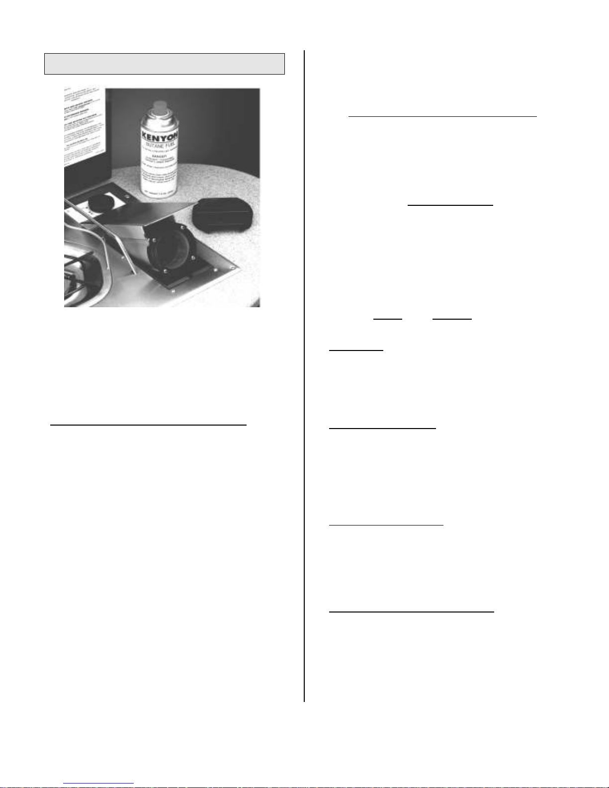
Correct Butane Fuel Canisters: Description and Where to Buy Them
Operating Controls and Features
Use the Correctly Sized Pots & Pans
Loading and Removing the Butane Fuel Canister, Igniting Burner
Using the Adjustable Pot Holders
Securing After Use
Closing Glass Lid
STORAGE OF SPARE BUTANE FUEL CANISTERS.............................................................. 11
MAINTENANCE....................................................................................................................... 13
User Maintenance
Factory-Only Maintenance
TROUBLESHOOTING............................................................................................................. 16
HOW TO CONTACT hbkvlk CUSTOMER SERVICE ........................................................ 18
RETURN POLICY.................................................................................................................... 18
WARRANTY ............................................................................................................................ 19
Copyright © 2005 by hbkvlk International, Inc.. All rights reserved. Reproduction in whole or in part without written permission is expressly
prohibited.

Specifications
COOKER CAPACITY
• Nominal gas flow rate: 150 grams/hour
• Capacity: (Qn: maximum) 2.1kW (7,172 Btu / hour)
FUEL
• I3B ISO Butane at Vapour Pressure in disposable cartridges containing
7.8 oz (220 grams) of fuel
FUEL CARTRIDGE TYPE
• Only KENYON
KENYON brand butane fuel cartridges type KBF-2 should be used in the KISS
KENYONKENYON
Stove. It may be hazardous to attempt to fit other types of gas cartridges.
APPLIANCE DIMENSIONS
• Width: 14 5/8” (370mm)
• Length: 13 ½” (346mm)
• Depth: 5 ¾” (146mm)
• Depth below counter surface: 4 ¾” (121mm)
WEIGHT
• 14.5 lbs. (6.6 kg)
DO NOT DISCARD THIS MANUAL
SAVE FOR FUTURE REFERENCE
1
Introduction
You are now the owner of the most innovative cooking
appliance in the marine industry. Your new hbkvlk
hfpp Cook Top brings new standards of convenience
and efficiency to your galley and your boating experience.
Our standards for quality assurance are the highest in the
industry. Over 70 years of experience in building marine
cooking appliances assures that you will receive exactly
what you paid for: years of trouble-free, safe and
dependable performance.
FEATURES * OF YOUR NEW hfpp
(See Fig. 1)
hfpp COOK TOP
hfpphfpp
Convenience
Clean
other liquid fuels, no wicks, no pumping, no soot, no
AC or DC power.)
Automatic
Instant
Simple
extraction.
Long
8 oz. butane canister
Built-in
Snap-out
Brushed
and good looks
Tempered
provides extra working space.
* KENYON hfpp is protected under U.S. and Foreign patents pending.
, modern butane gas cooking (no alcohol or
lighting (piezo spark igniter)
flame response from simmer to boil
, positive, butane fuel canister loading and
cooking time – from 2 to 4 hours from a single
adjustable pot holders
grate for easy cleanup
stainless steel construction for durability
glass lid hides stove when not in use,
Safety
Use this appliance only in a well-ventilated area.
Outside-vented
butane canister, provides safe venting if butane gas
canister leaks in service
Automatic
closed on lit burner.
Automatic
extinguished. (KISS CE models only)
Interlocks
correctly inserted.
Interlocks
safety shell end cap is in “open” position.
Two-motion
safety for children and against accidental ignition.
Interlock
overheated, resets when door is opened
hfpp
hfpp meets
hfpphfpp
safety standards.
UNPACKING
Handle the Cook Top carefully. Do NOT remove the
protective corrugated band – it is there to prevent the
glass lid and Cook Top assembly from separating from
the underpan until you are ready to mount them!
Inspect Contents of Carton
• Mounting screws (4)
• Template for counter top cut-out
Please contact the factory if any of these items are
missing. If any shipping damage is observed, NOW is
the time to contact your dealer.
Tools Needed for Installation
• Power Drill
• 1/2” Drill (13mm), center drill, 5/8” (16mm) hole saw
• Jigsaw (or router with 1/2” (13mm) diameter bits)
• Philips screw driver
• Flat blade screw driver
Installer-supplied Materials for Installation
• Vent hose, 5/8” (16mm) ID reinforced clear PVC,
length as necessary.
• Hose clamps (2), “mini” style, stainless steel
• Vent fitting: Perko 506DPCHR or similar
• Assorted nylon wire ties and/or clamps as needed to
secure vent hose against chafe
stops gas flow if fuel canister is
Your new hfpp is shipped with:
, built-in “safety shell” contains
flame shut-off if glass lid is accidentally
fuel shut-off if flame is inadvertently
prevent ignition if fuel canister is not
prevent closing gas compartment if
“push-to-turn” gas knob provides extra
and/or
exceeds
all relevant marine
2
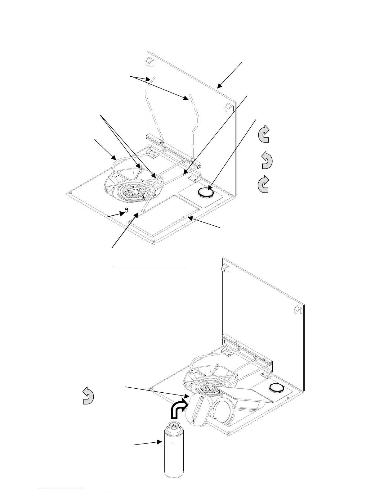
Fig. 1
-
KISS
(7)
POTHOLDERS stowed
(1)
GRATE
“Pinch” these 2
fingers to remove
grate for cleaning
(5)
POT HOLDERS deployed.
a) Loosen knurled knobs
and slide laterally to
adjust to pot size.
b) Wait until cool before
attempting to readjust or
stow!
Operating Controls
(2)
TEMPERED GLASS LID
Hinges down after Lidstay is
released
(3)
LIDSTAY
(4)
CONTROL KNOB
Turn CW to open
gas compartment
door
Push & turn CCW
to ignite burner
Turn back CW to
reduce flame height
(12)
FLAME FAILURE DEVICE
(FFD)(KISS CE only)
Push button and hold down while
igniting burner with Control Knob
(6)
• Wait until Lidstay is cool
• Press Lidstay firmly here to
(9)=hfpp=
hfpp=WITH GAS COMPARTMENT
hfpp=hfpp=
DOOR OPEN, READY TO LOAD
FUEL CANISTER
(10)
END CAP
Remove by turning CCW
TO CLOSE GLASS LID:
disengage from top pan
(8)
DOOR, Gas Compartment
(11)
BUTANE GAS
CANISTER
KKKK
EEEE
NNNN
YYYY
OOOO
NNNN
authorized governing body in their country.
A N Y O F TH E C OM PO NE NT S OF T H E CO OK
CAUTION!
(except the
Installation
MOUNTING THE KISS
Do not cut the opening in your countertop until you
ensure that there will be adequate horizontal and
vertical clearances from the Cook Top to the nearest
flammable materials- fabric, plastic, wood-
Locate the Cook Top Away from Flammable Materials
Before you cut the counter top:
Make certain the Cook Top is far enough away from
Minimum distances are:
HORIZONTAL: 16” (40cm)
It is the installer’s and/or purchaser’s
responsibility to ensure that the hfpp
Top is installed in a location such that a fire
hazard is not created.
Because various related Standards are always
undergoing revision, we urge you to contact
the ABYC for the latest Standards that satisfy
both U.S. and International requirements:
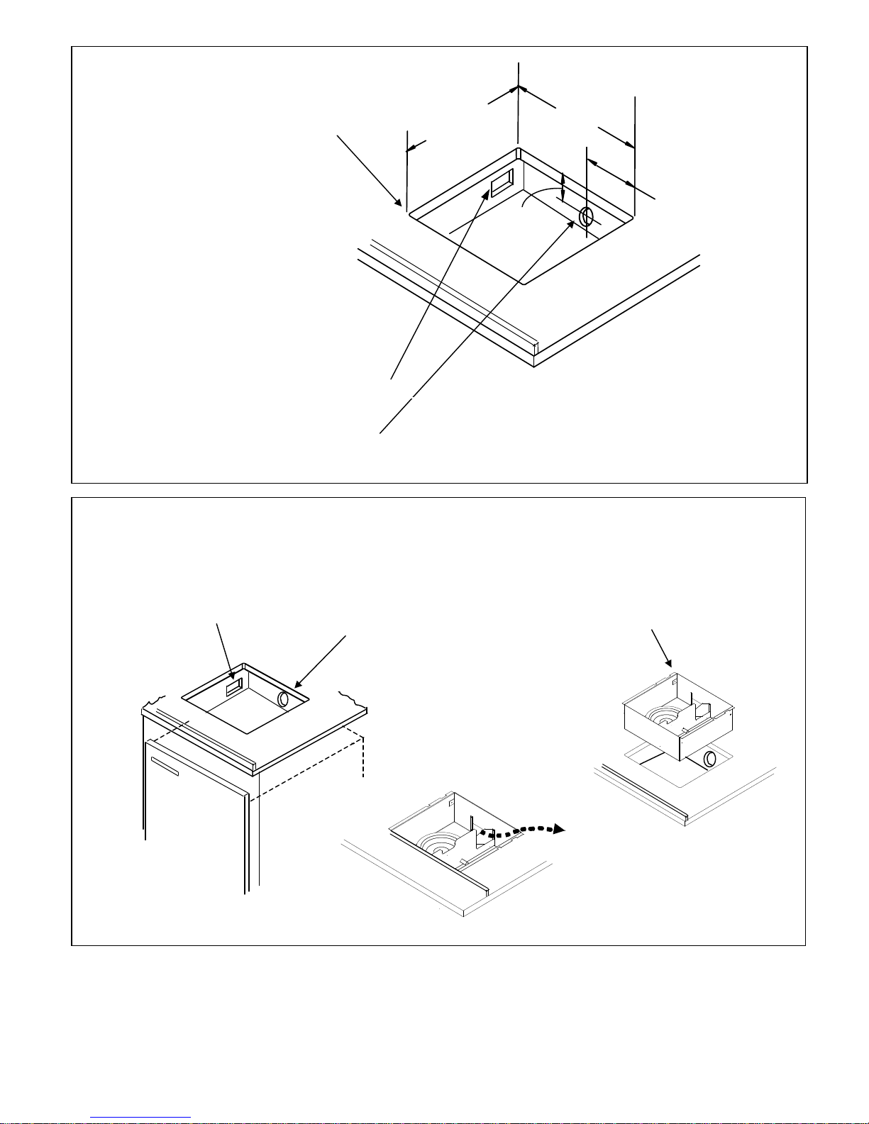
Providing Adequate Combustion Air (See Fig.’s 2 & 3)
Most of the air for the flame comes from under the
burner. Blocking or restricting this airflow will cause
incomplete combustion and may create dangerous levels
of carbon monoxide.
You must not install your Cook Top in a closed “box.”
After the Cook Top is mounted, there must be at least 8
square inches (52 square cm) of free air – supply opening
in whatever woodwork or cabinetry is surrounding the
Cook Top. If not, cut at least one opening 2” x 4”
(50mmm x 100mm) or three 2” (50mm) diameter holes,
etc.) More and/or larger openings are even better to
ensure against possible future blockage. (See Fig. 2)
American Boat & Yacht Council
3069 Solomons Island Road,
Edgewater, MD 21037-1416
TEL (410) 956-1050 FAX (410) 956-2737
Internet: abycinc@aol.com
European customers should contact the
KISS COOK TOP
KISS KISS
countertop itself).
Flammable materials!
VERTICAL: 39” (1m)
hfpp Cook
hfpphfpp
Cutting the Counter Opening
Use the full-sized TEMPLATE supplied with the cook top
to locate and mark the cutout. Carefully, mark and drill
the 4 cutout corners with a 1/2” drill (13mm). Use a
jigsaw or fine-toothed hand saw to connect them (or a
router with 1/2” bit (13mm).
The KISS Cook Top can be recessed in the counter so
that the top of the closed glass lid is flush with the
countertop surface. Before starting installation, ensure
that there will be adequate clearance for the glass lid to
hinge up without interference from the countertop at the
rear edge.
Mounting the Subpan (See Fig. 3)
Carefully cut the corrugated cardboard security band and
separate the galvanized steel underpan from the Cook
Top. Set the Cook Top aside on a clean surface.
G L A SS L ID B RE AK AG E C AN C AU SE I NJ UR Y
Trial-fit the BOTTOM PAN into the cutout locating the
“vee” opening at the rear (the vent hose will pass through
the opening). Clean the counter to remove all traces of
oil, dirt or grease. Remove the protective strips from the
foam adhesive tape on both flanges of the underpan;
press the flanges down firmly. Do not add any screws or
other fastenings – they will just create “dimples” in the
stove deck.
4
CAUTION!
D A MA G E TO G AS TU BE S OR
C O NN E CT IO NS C AN C AU S E GA S LE AK S
B E C A RE FU L N OT T O DA MA GE O R BE N D
DO NOT mount the Cook Top in the subpan
T O P!
at this time.
(2)
(1)
(1)
(2)
(4)
Route
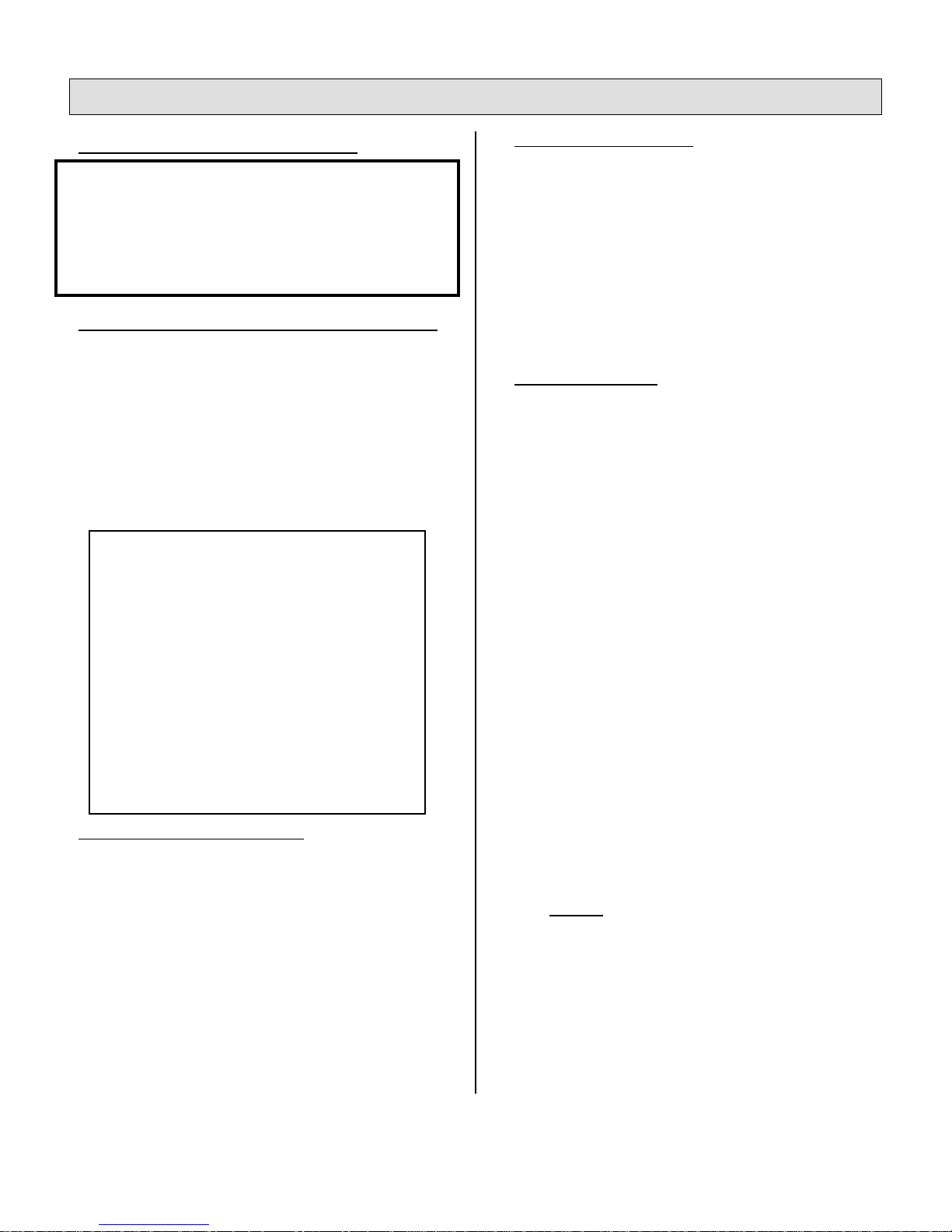
Fig. 2 – Cutout Dimensions
Use 1/2” (13mm) diameter
drill or router bit for corners
FRONT
(OPERATOR SIDE)
(3)
If Cook Top will be “boxed in” by existing
structures:
• Cut 2” x 4” (50mm x 100mm) opening for
combustion air anywhere in the surrounding
enclosure
• Cut 2” (50 mm) diameter hole for Vent Hose
where shown
Fig. 3 – Installing Cook Top into Counter
If Cook Top will be “boxed in” you must
provide at least 8 square inches of opening for
combustion air
12 1/2"
317.5mm
Hole for Vent Hose
at least 2” diameter
5
3 ¾”
(95mm)
333mm
Vent
Hose
(3)
Bottom Pan
 Loading...