

Page 1

COMPACT HI-FI SYSTEM
XD-SERIES
XD-A75
XD-A55
INSTRUCTION MANUAL
KENWOOD CORPORATION
This instruction manual is for some models.Model availability and features
(functions) may differ depending on the country and sales area.
B60-5007-00 00 MA (K, P) KW 0010 TINSE0365AWZZ
Page 2
BEFORE APPLYING POWER
Caution : Read this page carefully to ensure safe operation.
Units are designed for operation as follows.
U.S.A. and Canada........................ AC 120 V only
SAFETY PRECAUTIONS
WARNING :TO PREVENT FIRE OR ELECTRIC SHOCK, DO NOT
EXPOSE THIS APPLIANCE TO RAIN OR MOISTURE.
CAUTION
RISK OF ELECTRIC SHOCK
DO NOT OPEN
THE LIGHTNING FLASH WITH ARROWHEAD SYMBOL, WITHIN AN EQUILATERAL TRIANGLE, IS INTENDED TO ALERT THE USER TO THE PRESENCE OF UNINSULATED “DANGEROUS VOLTAGE” WITHIN
THE PRODUCT’S ENCLOSURE THAT MAY BE OF SUFFICIENT MAGNITUDE TO CONSTITUTE A RISK
OF ELECTRIC SHOCK TO PERSONS.
THE EXCLAMATION POINT WITHIN AN EQUILATERAL TRIANGLE IS INTENDED TO ALERT THE USER
TO THE PRESENCE OF IMPORTANT OPERATING AND MAINTENANCE (SERVICING) INSTRUCTIONS
IN THE LITERATURE ACCOMPANYING THE APPLIANCE.
The marking of products using lasers
(Except for some areas)
CLASS 1
LASER PRODUCT
The marking is located on the rear panel and
says this product has been classified as Class
1. It means that there is no danger of hazardous radiation outside the product
EN
2
CAUTION: TO REDUCE THE RISK OF ELECTRIC SHOCK,
DO NOT REMOVE COVER (OR BACK). NO USERSERVICEABLE PARTS INSIDE. REFER SERVICING TO
QUALIFIED SERVICE PERSONNEL.
Page 3
CONTENTS
Page
BEFORE APPLYING POWER............................... 2
SAFETY PRECAUTIONS ...................................... 2
ACCESSORIES .................................................... 3
HANDLING OF DISCS AND TAPES ..................... 4
NAMES OF CONTROLS AND INDICATORS
....................................................................... 5 - 7
PREPARATION FOR USE ..............................8 - 10
SETTING THE CLOCK .................................. 11 -12
SOUND CONTROL ........................................... 12
COMPACT DISC OPERATION ..................... 13 - 17
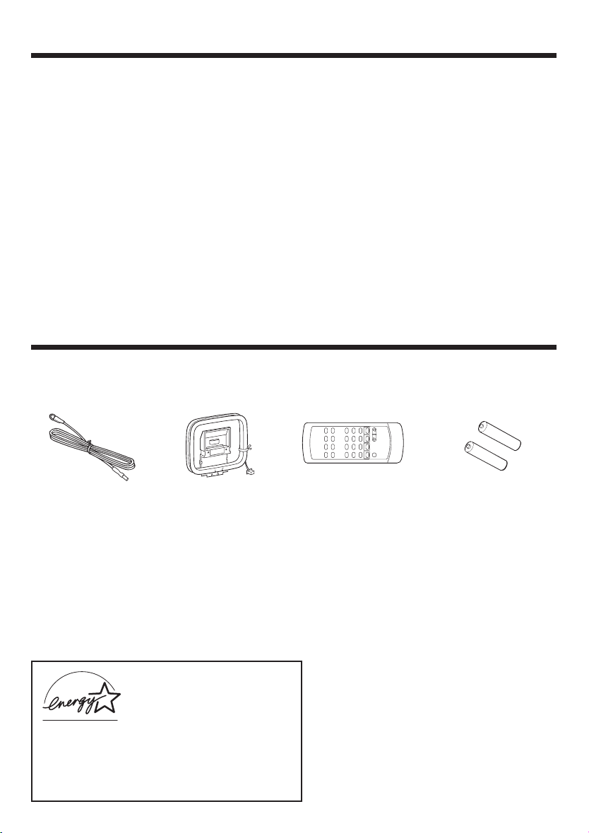
ACCESSORIES
FM Antenna
(1)
AM Loop Antenna
(1)
Page
RADIO OPERATION ................................... 18 - 20
CASSETTE OPERATION .................................... 21
RECORDING (TAPE B only)........................ 22 - 23
HOW TO USE THE BUILT-IN TIMER............ 24 - 26
USING EXTERNAL UNITS ................................. 27
RESETTING THE MICROCOMPUTER ............... 28
TRANSPORTING THE UNIT............................... 28
MAINTENANCE ................................................ 29
SPECIFICATIONS ....................................... 31 - 32
Remote Control
(1)
“AA” size battery (UM/
SUM-3, R6, HP-7 or similar)
(2)
As an ENERGY STAR® Partner, Kenwood Corporation has determined that this products meets the
ENERGY STAR® guidelines for energy efficiency.
This product can save energy. Saving energy reduces
air pollution and lowers utility bills.
EN
3
Page 4
HANDLING OF DISCS AND TAPES
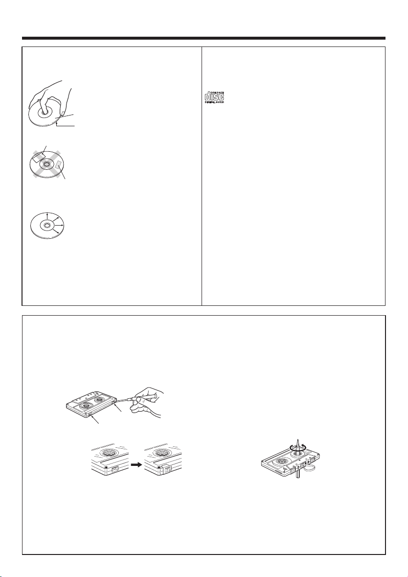
Disc handling precautions
Handling
Hold the discs so that you do not
touch the playing surface.
Label side
Playing side
Sticker
Do not attach paper or tape to either the playing side or the label
side of the discs.
Sticky paste
Cleaning
If fingerprints or foreign matter
become attached to the disc,
lightly wipe the disc with a soft
cotton cloth (or similar) from the
center of the disc outwards in a
radial manner.
Storage
When a disc is not to be played for a long period
of time, remove it from the player and store it in
its case.
Notes on cassette tape
Safety tab (accidental erasure prevention tab)
After an important recording has been finished,
break the safety tab, to prevent the recorded contents from being erased or recorded on accidentally.
Discs which can be played with this unit
CD (12 cm, 8 cm) and the audio part of CDV, CD-G,
CD-EG and CD-EXTRA. Use discs that comply with
the IEC standard, for example a disc carrying the
marking on the label surface.
Never play a cracked or warped disc
During playback, the disc rotates at high speed in
the player. Therefore, to avoid danger, never use a
cracked or deformed disc or a disc repaired with
tape or adhesive agent. Please do not use discs
which are not round because they may cause a
malfunction.
Disc accessories
The disc accessories (stabilizer, protection sheet,
protection ring, etc.) which are marketed for improving the sound quality or protecting discs as well as
the disc cleaner should not be used with this system because they may cause malfunction.
To store cassette tapes
Do not store the tapes in a place which is subject
to direct sunlight, or near equipment that generates heat. Keep the cassette tapes away from
any magnetic field.
When there is slack in the tape
For A side
For B side
In such a case, insert a pencil into the reel hole
and wind the reel hub to remove the slack.
To re-record
Apply tape only to the position where the tab has
been removed.
Note :
Do not use an endless tape, as this could damage the mechanism of the unit.
•
• Do not use a cassette with more than 90 minutes recording time, for the tape used in such a cassette
is very thin and tends to cause troubles such as engantlement around the pinch roller or cutting of
tape.
EN
4
Page 5
NAMES OF CONTROLS AND INDICATORS
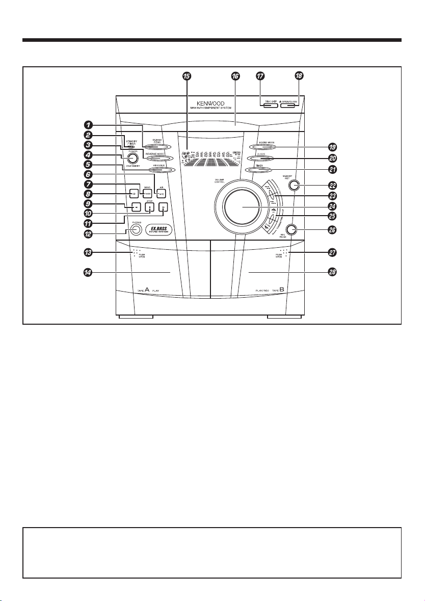
FRONT PANEL
1 EX.BASS / DEMO button
2 STANDBY / TIMER indicator
3 REVERSE MODE button
4 POWER / ON / STANDBY button
5 VIDEO / AUX button
6 TAPE (A/B) button
7 TUNER (BAND) button
8 CD button
9 2 (Reverse play) button
0 7 STOP button
! 3 (Play / repeat) button
@ PHONES socket
# PUSH OPEN (Tape A)
$ Tape A cassette compartment
% Display
^ Disc tray
& DISC SKIP button
* 0 OPEN / CLOSE button
( SOUND MODE button
) CLOCK button
¡ TIMER button
™ MEMORY / SET button
£ P. CALL (4 1 ¡ ¢) buttons
¢ VOLUME CONTROL knob
∞ TUNING / TIME (%UP fiDOWN) buttons
§ REC PAUSE button
¶ PUSH OPEN (Tape B)
• Tape B cassette compartment
Standby mode
While the standby indicator of the unit is lit, a small amount of current is flowing into the unit’s internal
circuitry to back up the memory. This condition is referred to as the standby mode of the unit. While
the unit is in the standby mode, it can be turned ON from the remote control unit.
EN
5
Page 6
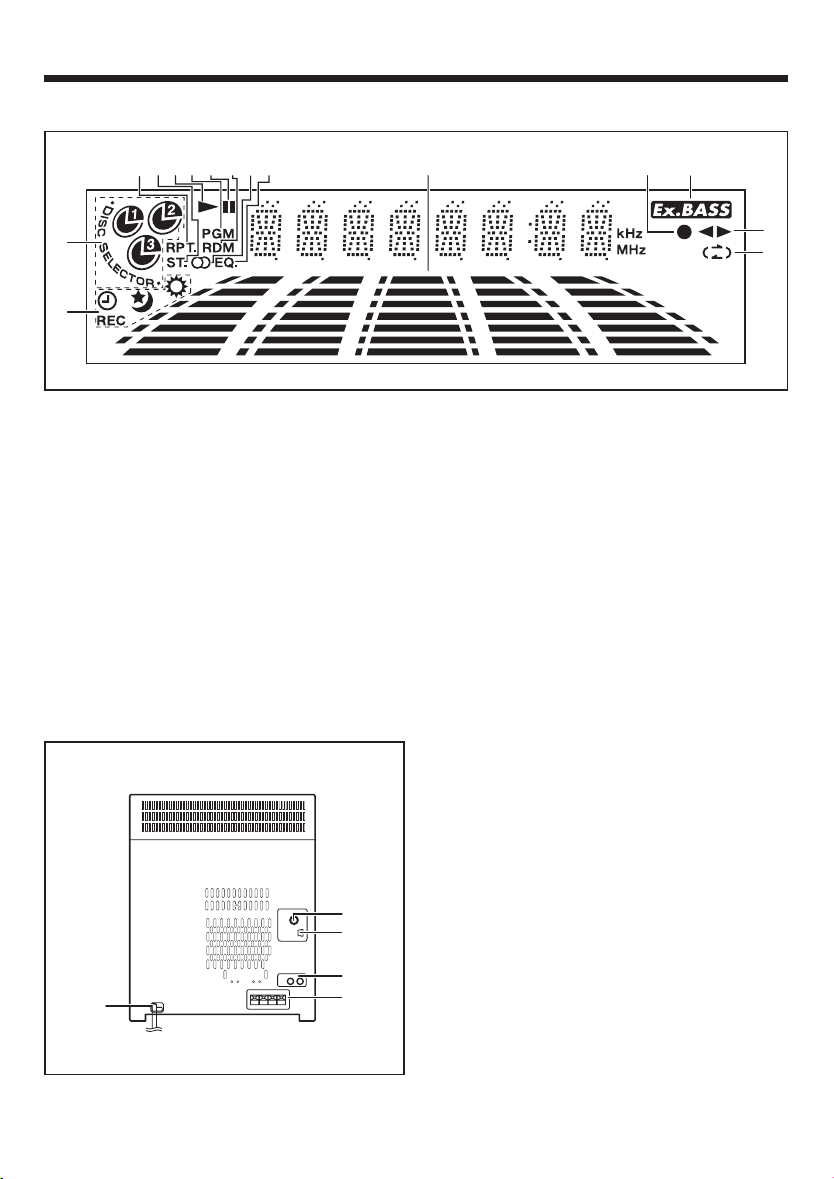
DISPLAY
3
4
5
6
7
8
2
1
1 Timer Related Indicator
2 Disc Number Indicator
3 Repeat Indicator
4 FM Stereo Mode Indicator
5 Play Indicator
6 Programme Indicator
7 Pause Indicator
8 Random Play Indicator
REAR PANEL
90
!
9 Tuned Indicator
0 Equalizer Indicator
! Spectrum Analyzer / Volume level Indicator
@ Record Indicator
# Extra Bass Indicator
$ Forward / Reverse Play Indicator
% Reverse Mode Indicator
1 AC Power Cord
2 FM 75 Ω Antenna Socket
3 AM Loop Antenna Socket
4 Video / Auxiliary (Audio Signal) Input sockets
5 Speaker Terminals
@
#
$
%
2
3
4
1
EN
6
5
Page 7
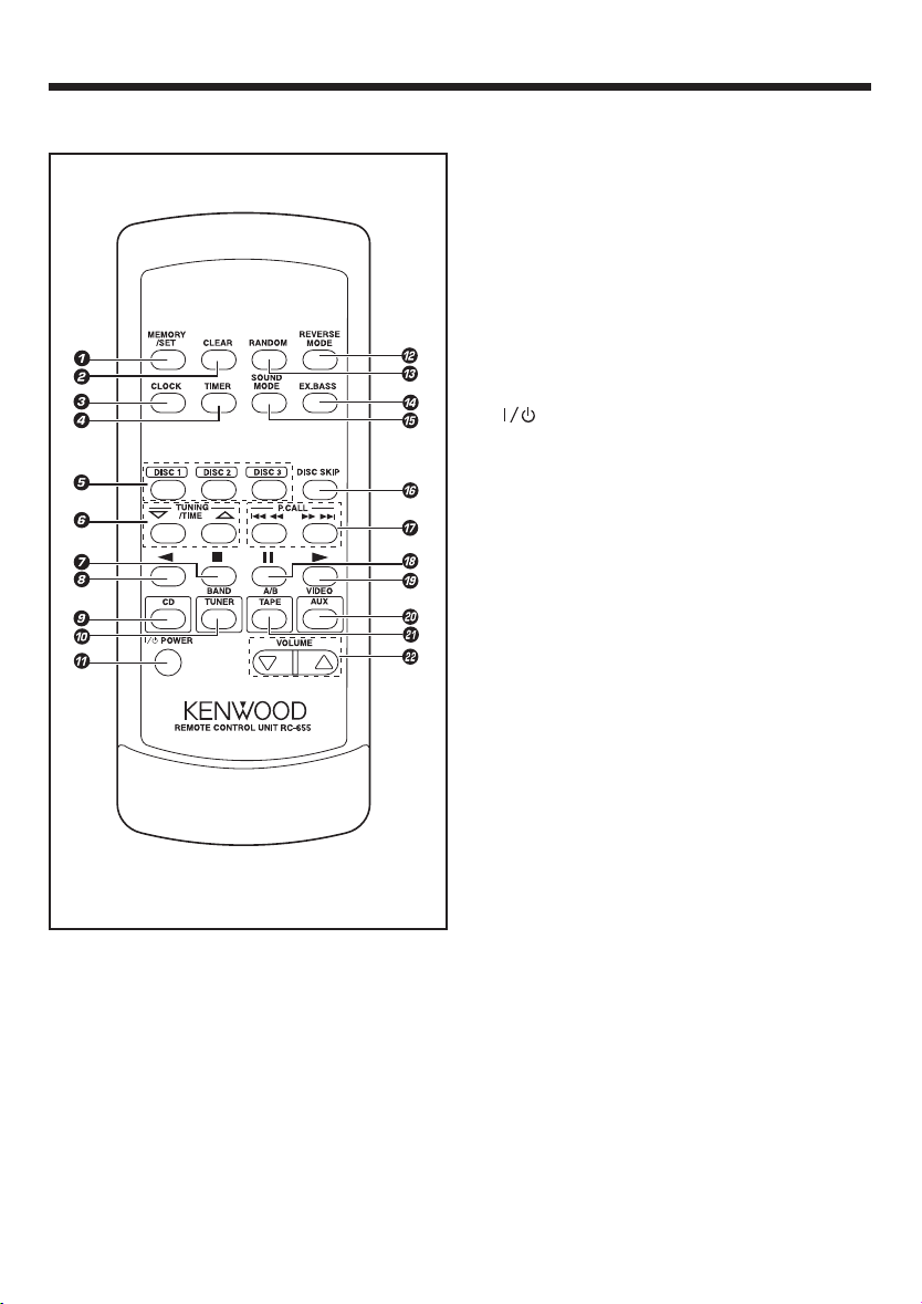
REMOTE CONTROL
1 MEMORY / SET button
2 CLEAR button
3 CLOCK button
4 TIMER button
5 Disc Number Select buttons
6 TUNING / TIME (% fi) buttons
7 7 (Stop) button
8 2 (Reverse Play) button
9 CD button
0 TUNER (BAND) button
! POWER button
@ REVERSE MODE button
# RANDOM button
$ EX.BASS button
% SOUND MODE button
^ DISC SKIP button
& P. CALL (4 1 ¡ ¢) buttons
* 8 (Pause) button
( 3 (Play / Repeat) button
) VIDEO / AUX button
¡ TAPE (A/B) button
™ VOLUME buttons
EN
7
Page 8
PREPARATION FOR USE
• Unplug the AC power cord from the AC socket before connecting or disconnecting any component.
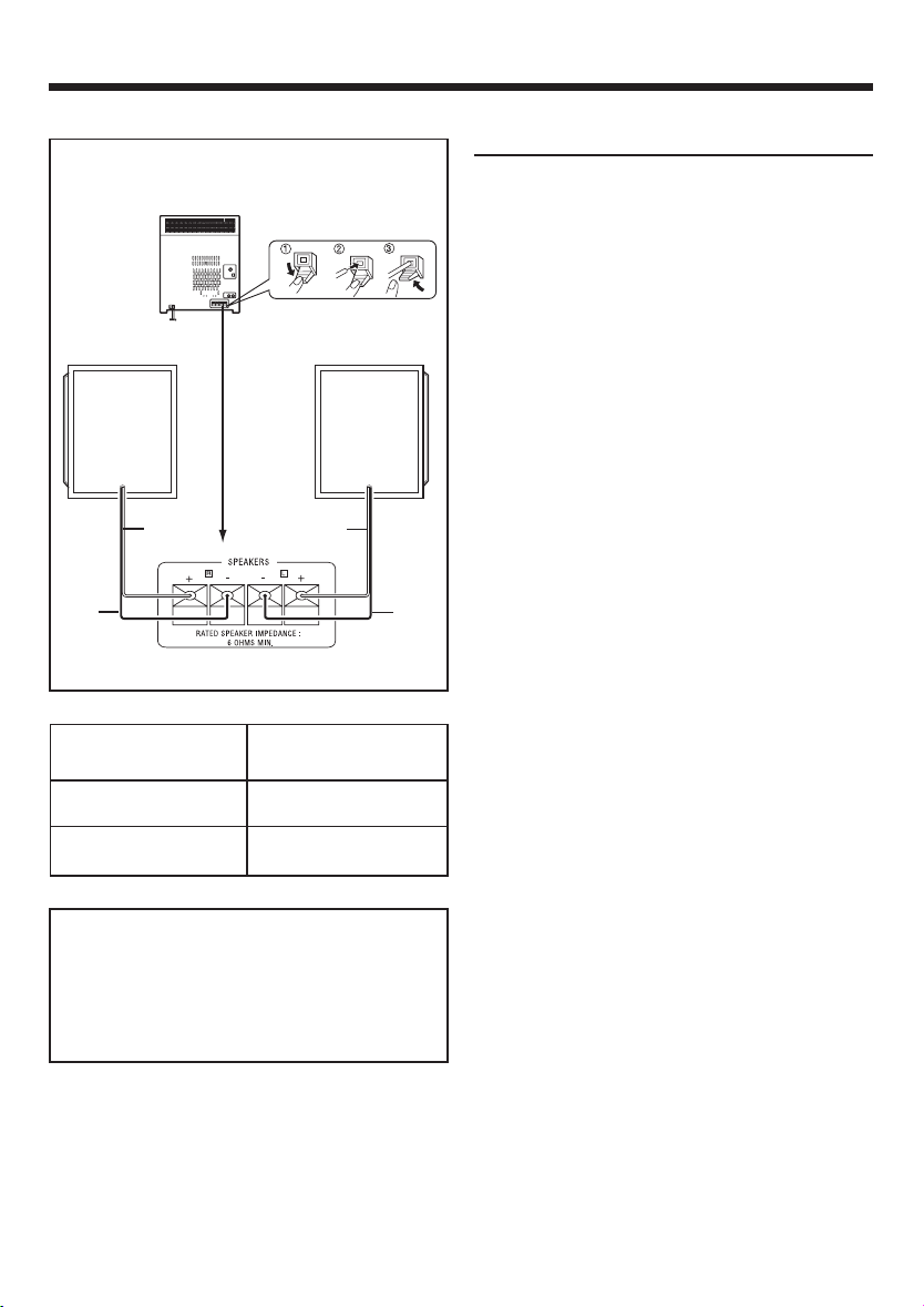
Speaker connection
Speakers (XD-A75, XD-A55)
Right speaker
Black
Red
Left speaker
Red
Black
Connect each speaker wire to the SPEAKERS terminals as shown. Use speakers with an impedance
of 6 ohms or more, as lower impedance speakers
can damage the unit.
Connect the black wire to the minus (-) terminal,
and the red wire to the plus (+) terminal.
Caution :
• Do not mix the right channel and left channel
wiring when connecting the speakers to the unit.
The right speaker is the one on the right side
when you are facing the front of the unit.
• Do not let bare speaker wires touch each other
as this may damage the amplifier and/or speakers.
• Do not allow any objects to fall into or to be
placed in the bass reflex ducts.
• Do not stand or sit on the speakers. If the speakers fall or collapse, you may be injured.
System Name
XD-A75
XD-A55
Speaker Model
Name
LS-N70S
LS-N50S
CAUTION
Be sure to adhere the following, or proper
ventilation will be blocked causing damage
or fire hazard.
÷ Do not place any objects impairing heat
radiation onto the top of unit.
EN
8
Page 9
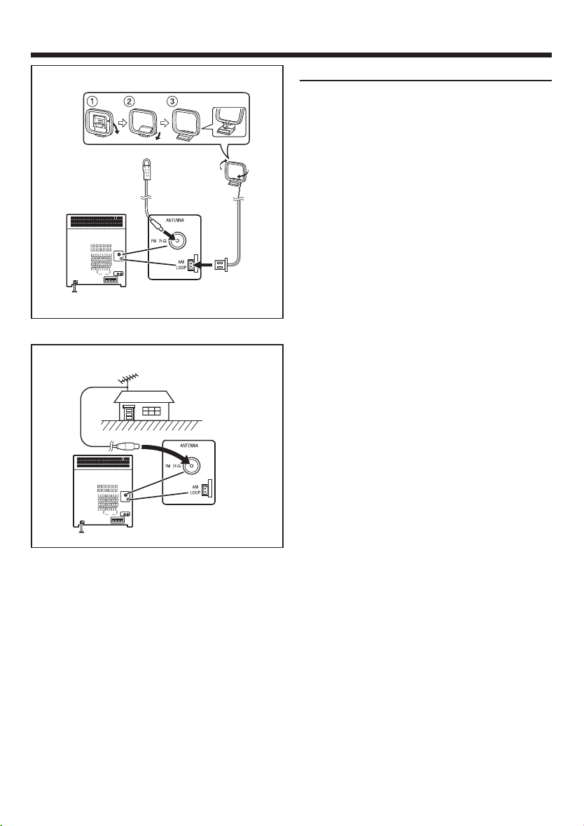
Antenna connection
Supplied FM antenna
Connect the FM antenna wire to the FM 75 Ω terminal and position the FM antenna wire in the direction where the strongest signal can be received.
FM antenna
AM loop
antenna
External FM antenna
Supplied AM loop antenna
Connect the AM loop antenna wire to the AM LOOP
socket. Position the AM loop antenna for optimum
reception.
Place the AM loop antenna on a shelf, etc., or attach it to a stand or a wall with screws (not supplied).
Notes :
• Do not place the antenna on the main unit as it
may result in noise pickup from the internal digital electronics.
Place the antenna away from the unit for better
reception.
• If the AM loop antenna and the FM antenna wire
are placed near to the AC power cord, interference may result.
External FM antenna
Use an external FM antenna if you require better
reception.
Consult your dealer.
EN
9
Page 10

Demo mode
/
When the AC power cord is first connected, the
unit will enter the demonstration mode.
EX.BASS
DEMO
• 2 “AA” size batteries (UM/SUM-3, R6,
HP-7 or similar)
To cancel the demonstration mode :
Press the EX.BASS/DEMO button.
• The demonstration mode will be cancelled and
the unit will be in the low power consumption
mode.
To return to the demonstration mode :
When the unit is in the standby mode, press the
EX.BASS/DEMO button again.
Notes :
• When the unit is in the low power consumption
mode, the display will disappear.
• When the power is on, the EX.BASS/DEMO button can be used to select the extra bass mode.
Remote control
• When inserting or removing the batteries, push
them towards the battery terminals.
• Installing the batteries incorrectly may cause the
unit to malfunction.
Precautions for battery use :
• Replace all old batteries with new ones at the
same time. Do not mix old and new batteries.
• Remove the batteries if the unit will not be used
for long periods of time. This will prevent potential damage due to battery leakage.
• Do not use rechargeable batteries (nickelcadmuim battery, etc.)
Note concerning use :
• Replace the batteries if the operating distance
30
30
EN
10
is reduced or if the operation becomes erratic.
• Periodically clean the transmitter LED on the remote control and the sensor on the main unit
with a soft cloth.
• Exposing the sensor on the main unit to strong
light may interfere with operation. Change the
lighting or the direction of the unit.
• Keep the remote control away from moisture,
excessive heat, shock, and vibrations.
Page 11

SETTING THE CLOCK
In this example, the clock is set for the 12 hours
(AM 12:00) system.
POWER
ON/STANDBY
TUNING/TIME
(fi %)
2
3
4
MEMORY
/SET
CLOCK
POWER
CLOCK
MEMORY
/SET
TUNING/
TIME (%UP
fiDOWN)
1 Press the POWER / ON/STANDBY button to
enter the standby mode.
2 Press the CLOCK button.
3 Within 5 seconds, press the MEMORY/SET
button.
4 Press the TUNING/TIME (%UP or fiDOWN) but-
ton to select the time display mode.
“AM 12:00” : The 12-hours display will appear.
(AM 12:00 - PM 11:59)
“AM 0:00” : The 12-hours display will appear.
(AM 0:00 - PM 11:59)
“0:00” : The 24-hours display will appear.
(0:00 - 23:59)
• Note that this can only be set when the unit is
first installed or it has been reset (see page 28
- RESETTING THE MICROCOMPUTER).
5 Press the MEMORY/SET button.
6 Press the TUNING/TIME (%UP or fiDOWN)
button to adjust the hour.
• Press the TUNING/TIME (%UP or fiDOWN)
button once to advance the time by 1 hour.
Hold it down to advance continuously.
• When the 12-hours display is selected, “AM”
will change automatically to “PM”
7 Press the MEMORY/SET button.
5
8 Press the TUNING/TIME (%UP or fiDOWN)
button to adjust the minutes.
• Press the TUNING/TIME (%UP or fiDOWN)
6
7
8
9
button once to advance the time by 1 minute.
Hold it down to change the time in 5 minutes
intervals.
• The hour setting will not advance even if min-
utes advance from “59” to “00”.
9 Press the MEMORY/SET button.
• The clock starts operating from “0” second.
(Second are not displayed.)
And then the clock display will disappear after
a few seconds.
11
EN
Page 12

To see the time display :
Press the CLOCK button.
• The time display will appear for about 5 seconds.
Note :
• The clock display will flash on and off at the push
of the CLOCK button when the AC power supply is restored after a power failure occurs or
after the AC power cord is disconnected. If this
happens, follow the procedure below to change
the clock time.
SOUND CONTROL
Main unit Remote control
Main unit Remote control
To change the clock time :
1 Press the CLOCK button.
2 Within 5 seconds, press the MEMORY/SET but-
ton.
3 Perform steps
6 - 9 on page 11 .
To change the time display mode :
1 Perform steps 1 - 2 in the section “RESET-
TING THE MICROCOMPUTER”, on page 28.
2 Perform step
1 - 9 on page 11.
Volume
(Main unit operation)
When the VOLUME CONTROL is turned clockwise,
the volume will increase. When it is turned anti-clockwise, the volume will decrease.
(Remote control operation)
Press the VOLUME up button (% ) to increase the
volume and the VOLUME down button (fi ) to decrease the volume.
Extra bass
When the power is first turned on, the unit will enter the extra bass mode which emphasises the bass
frequencies, and “Ex. BASS” will light up.
To cancel the extra bass mode, press the EX. BASS/
DEMO (EX. BASS) button, and “Ex. BASS” will goes
off.
Main unit Remote control
FLAT ROCK POPS
SAMBA CLASSIC
EN
12
JAZZ
Pre-programmed equalizer
When the SOUND MODE button is pressed, the
current equalizer mode setting will be displayed. To
change to a different mode, press the SOUND
MODE button repeatedly.
FLAT : The sound is not modified.
ROCK : Bass and treble are emphasised.
POPS : Bass and treble are slightly emphasised.
JAZZ : Treble is cut a little.
CLASSIC : Treble is reduced a lot.
SAMBA : Treble is slightly emphasised.
• When ROCK, POPS, JAZZ, CLASSIC or SAMBA
is selected, “EQ” will light up.
Page 13

COMPACT DISC OPERATION
12 cm (5")
8 cm (3")
7 STOP
7
8
CD playback
Press the POWER / ON/STANDBY button to turn
1
the power on.
2 Press the CD button.
3 Press the 0 OPEN/CLOSE button to open the
disc tray.
4 Place the CD(s) on the disc tray, label side up.
• CDs can be placed on any open position on the
disc tray.
• Be sure to place 8cm (3”) CD(s) in the middle of
the disc trays.
Caution :
Do not stack CDs in the tray. This can damage the
player and the CDs.
5 When loading a third disc, press the DISC SKIP
button to turn the disc tray, then place the CD in
the open position.
6 Press the 0 OPEN/CLOSE button to close the
disc tray.
• The total number of tracks and the total playing
time for one disc will be displayed. At this time,
the disc number indicator is flashing.
• The music schedule will be displayed only for
the number of tracks on the disc.
7 Press the desired disc number button ( DISC 1 -
DISC 3).
8 Press the 3 button.
• Playback will begin from track 1 on the disc you
have selected to play.
• After the disc finishes playing, the next disc will
automatically play.
• When there is no CD in one of the disc 1 - 3
positions, that position will be skipped and the
next CD will be played.
• When the last track on the third disc has finished
playing, the unit will stop automatically.
13
EN
Page 14

To interrupt playback :
1
1 Press the 8 button on the remote control.
•“8” will light up.
2 Press the 3 button to resume playback from the
same point.
To stop playback :
Press the 7 STOP button.
To remove the CDs :
Whilst in the stop mode, press the 0 OPEN/CLOSE
button.
• The disc tray will open. Remove the two discs.
Then, press the DISC SKIP button to rotate the
disc tray and remove the remaining disc.
After use :
Press the POWER / ON/STANDBY button to enter
the standby mode.
Cautions :
•
Do not carry the unit with discs left in the disc
trays. The disc may become loose inside the
unit and they may be damaged or cause damage to the unit. This may also cause malfunctions.
• Do not place two CDs in one disc position.
• Do not push the disc tray whilst it is moving.
• Do not attempt to turn the disc tray by hand.
This may cause malfunctions.
• If the power fails whilst the tray is open, wait
until the power is restored.
• If the disc tray is stopped forcibly, “ERR” will
appear in the display and the unit will not function.
If this occurs, press the POWER / ON/STANBY
button to enter the standby mode and then turn
the power on again.
• If TV or radio interference occurs during CD
operation, move the unit away from the TV or
radio.
• If a disc is damaged, dirt, or loaded upside
down, the disc will be skipped and the next
disc will automatically play.
Disc number selection
When stopped, press the DISC SKIP button.
1
2 Press the 3 button.
• The next disc playback will begin, after which
each following disc will be played sequentially.
DISC 1 - DISC 3
EN
14
2
Notes :
• When the DISC SKIP button is pressed during
playback, playback will begin automatically from
the next disc. (It is not necessary to press the 3
button.)
• When one of the disc number buttons (DISC 1DISC 3) is pressed during playback, playback of
the selected disc will begin automatically. (It is
not necessary to press the 3 button.)
1
2
Page 15

Random play
(Remote control operation)
The tracks on the disc(s) can be played in random
order automatically.
1 Load a disc(s) and close the disc tray.
2 Press the RANDOM button to begin random play.
RANDOM
• “RDM” will light up.
Notes :
P.CALL
7
4 1 ¡ ¢
3
• If you press the P. CALL ¡ ¢ button during
random play, you can move to another track. On
the other hand, the P. CALL 4 1 button does
not allow you to move to the previous track. The
beginning of the track being played will be located.
• When using random play, be sure to press the 7
STOP button after you are through listening.
Otherwise, the disc(s) will play continuously.
• In random play the unit will select and play tracks
automatically. (You cannot select the order of the
tracks.)
To cancel random play :
Press the 3 button.
Tracks Skipping
Tracks skipping will automatically locates the beginning of any track.
To listen again to the track being
played :
P.CALL
3
4 1
¡ ¢
Press the P. CALL 4 1 button for less than 0.5
second during playback.
To move to the beginning of the next
track :
Press the P. CALL ¡ ¢ button for less than 0.5
second during playback.
• To skip a number of tracks at one time, press
the P. CALL 4 1 or ¡ ¢ button repeat-
edly until the desired track number is shown.
3
P.CALL
4 1 ¡ ¢
• To start playback from a desired track, press the
P. CALL 4 1 or ¡ ¢ button whilst in
the stop mode to select the track number, and
then press the 3 button.
Note :
Tracks skipping can only search for music on a
single disc.
15
EN
Page 16

7 STOP
Cue and review
Load a disc and begin playback.
1
2 Hold down the P. CALL ¡ ¢ button for audi-
ble fast forward, and hold down the P. CALL
4 1 button for audible fast reverse.
P.CALL
4 1
¡ ¢
3 Normal playback will resume when the P. CALL
4 1 or ¡ ¢ button is released.
Notes :
• When the end of the disc is reached whilst
cueing, “END” will appear in the display and CD
operation will be paused. (Even though the next
disc has been loaded, the disc will not be
switched.)
Press the P. CALL 4 1 button for fast reverse or press the 7 STOP button to stop CD
7
P.CALL
4 1 ¡ ¢
operation.
• If the beginning of the disc is reached whilst reviewing, the mode will automatically switch to
normal playback at that point.
Repeat play
16
7 STOP
EN
All tracks on up to 3 discs, or a programmed sequence can be continuously repeated.
3
To repeat all tracks on up to 3 discs :
Press the 3 button twice.
• “RPT.” will light up.
To repeat a programmed sequence :
1 Programme a sequence of up to 32 tracks.
2 Press the 3 button again.
• “RPT.” will light up.
To cancel repeat play :
Press the 3 button again.
7
3
• “RPT.” will goes off.
Note :
• When using repeat play, be sure to press the 7
STOP button after you are through listening.
Otherwise, the CD(s) will play continuously.
Page 17

Program Playback
You can playback the tracks on the CDs in the disc
1-3 position in any order desired. By specifying the
disc numbers from 1 to 3, and the track numbers
from 1 to 99, you can choose up to 32 selections
for playback in the order you like.
1 When in the stop mode, use the disc number
buttons (DISC 1 - DISC 3) to select the desired
disc number.
2 Press the P. CALL 4 1 or ¡ ¢ button
to select the desired track.
3 Press the MEMORY/SET button.
• “PGM” will light up to show that the pro-
3
5
2
grammed sequence is being entered into
memory.
4 Repeat steps 1 - 3 for any other track. Up to
32 tracks can be programmed.
• If you make a mistake whilst in the program-
ming mode (“PGM” will light up) or if you wish
to change your selections, the programmed
tracks can be cleared by pressing the CLEAR
button. The tracks will be cleared sequentially,
3
CLEAR
1
starting with the last track entered.
5 Press the 3 button to start playback of pro-
grammed selections.
2
5
To clear the programmed selections :
Press the CLEAR button on the remote control
whilst the disc is stopped.
• Each time the button is pressed, one track will
be cleared, beginning with the last track programmed.
Notes :
• Opening the disc tray automatically cancels the
programmed sequence.
• Even if you press the POWER / ON/STANDBY
button to enter the standby mode or the function is changed from CD to some other function, the programmed selections will not be
cleared.
• During program playback operation, random play
is not possible.
17
EN
Page 18

RADIO OPERATION
Tuning
1
Press the POWER / ON/STANDBY button to turn
the power on.
2 Press the TUNER (BAND) button.
3 Press the TUNER (BAND) button to select the
desired frequency band. (FM ST, FM or AM)
4 Press the TUNING/TIME (%UP or fiDOWN) but-
ton to tune into the desired station.
1
2,3,
5,6
4
1
2,3,
5,6
4
After use :
Press the POWER / ON/STANDBY button to enter
the standby mode
Note :
•
The last station turned in will be recalled, even
after changing the tuning band or the function,
or after switching the unit to the standby mode.
Manual tuning :
Press the TUNING/TIME (%UP or fiDOWN) button
as many times as required to adjust the frequency
shown on the display to the frequency of the desired station.
Auto tuning :
When the TUNING/TIME (%UP or fiDOWN) button
is pressed for more than 0.5 second, scanning will
start automatically and the tuner will stop at the
first receivable broadcast station.
Notes :
•
When radio interference occurs during auto scan
tuning, auto scan tuning may stop automatically
at that point.
• If a weak station signal is found during auto scan
tuning, the station will be skipped.
• To stop the auto tuning, press the TUNING/TIME
(%UP or fiDOWN) button again.
5 To receive an FM stereo transmission, press the
TUNER (BAND) button so that the “ST.” indicator on the display lights up.
• “ ” will light up when an FM broadcast is in
stereo.
6 If the FM reception is weak, press the TUNER
(BAND) button so that the “ST.” indicator goes
off.
• The reception changes to mono, the sound be-
comes clearer.
18
EN
Page 19

MEMORY/
/
SET
MEMORY
SET
P.CALL
4 1
¡ ¢
P.CALL
4 1 ¡ ¢
Preset tuning
You can store up to 40 stations in memory (40 stations consisting of any combination of FM and AM
stations you like) and recall them at the push of a
button.
To enter stations into memory :
Perform steps 1 - 6 in the “Tuning” section
1
(page 18).
2 Press the MEMORY/SET button.
• “PGM” and the preset channel number will flash.
3 Within 30 seconds, press the P. CALL (4 1
or ¡ ¢) button to make the preset channel
number flash in the display.
• The order of the station stored in memory, starts
with preset channel 1.
4 Within 30 seconds, press the MEMORY/SET
button to store that station in the selected station preset number memory.
• If the “PGM” and preset number go out before
the station is memorized, repeat the operation
from step
2.
5 Repeat steps 1 - 4 to set other preset sta-
tions, or to change a preset station.
• When a new station is stored in the selected
station preset number memory, the previous
stored contents will be erased.
To recall a memorised station :
Press the P. CALL (4 1 or ¡ ¢) button for
less than 0.5 second to select the desired station.
• The stations (preset channel number, frequency
band) which have been stored in memory will
appear in the display in numerical order, irrespective of the frequency bands.
Notes :
• When searching for a memorized station, do not
press the P. CALL (4 1 or ¡ ¢) for
more than 0.5 second.
• When the P. CALL (4 1 or ¡ ¢) button
is pressed for more than 0.5 second, the unit
will enter the preset memory scan mode.
Backup function :
The backup function protects all station presets for
a few hours should there be a power failure or the
AC power cord is removed from the AC socket.
19
EN
Page 20

EX.BASS
/DEMO
POWER
ON/STANDBY
TUNER
(BAND)
P.CALL
4 1
¡ ¢
Preset memory scan
The stations saved in the preset memory can be
scanned automatically.
1 To scan the preset stations, press the P. CALL
(4 1 or ¡ ¢) button for more than 0.5
second.
• The station preset number will flash and the pro-
grammed stations will be tuned in sequentially,
for 5 seconds each.
2 Press the P. CALL (4 1 or ¡ ¢) button
again to stop the memory scan at the desired
station.
Note :
When the preset memory dose not have any stations stored in it, the preset memory scan will not
function.
P.CALL
4 1 ¡ ¢
To erase all the contents in the preset
memory :
1 Press the POWER / ON/STANBY button to enter
the standby mode.
2 Press the POWER / ON/STANDBY button whilst
holding down the TUNER (BAND) button and the
SOUND MODE button.
• “PGM” will light up and “TUNER CL” will
appear.
• After performing this operation, all of the preset
memory information will be erased.
20
EN
Page 21

CASSETTE OPERATION
REVERSE
MODE
1
2,5
7 STOP
6
3
4
3
4
P.CALL
4 1
¡ ¢
TAPE A or TAPE B playback
Press the POWER / ON/STANDBY button to turn
1
the power on.
2 Press the TAPE (A/B) button.
3 Open the cassette door by pushing the area
marked “PUSH OPEN”.
4 Load the cassette into the TAPE A or TAPE B
cassette compartment.
5 With cassette in both decks, press the TAPE (A/
B) button to switch operation from one deck to
the other.
6 Press the 3 button to start playback.
• When playback is performed using the remote
control, press the 3 button.
To stop playback :
Press the 7 STOP button.
Fast forward/rewind :
1 Press the 7 STOP button, then press the TAPE
(A/B) button to select TAPE A or TAPE B.
2 To advance the tape, press the P. CALL ¡ ¢
button. To rewind it, press the P. CALL 4 1
button.
6
1
Caution :
•
To remove the cassette tape, press the 7 STOP
button, and then open the cassette compartment.
• Before changing from one tape operation to an-
P.CALL
4 1 ¡ ¢
7
2,5
other, press the 7 STOP button.
• If a power failure occurs during tape operation,
the tape head will remain engaged with the tape
and the cassette door will not open. In this case,
wait until power is restored.
Selection of reverse mode (Tape B
only) :
Press the REVERSE MODE button repeatedly to
select the following setting :
• “ ” .... Playback stops after having played both
sides of tape in a deck.
• “ “ ..... Endless playback of both sides of tape.
• “ “ ..... Playback stops after having played one
side of tape.
EN
21
Page 22

RECORDING (TAPE B only)
• When recording important selections, be sure to make a preliminary test to ensure that the desired
material is being properly recorded.
• The volume and sound quality can be adjusted with no effect on the recorded signals (Variable Sound
Monitor).
• Metal and CrO
7 STOP
2
tapes should not be used for recording or dubbing.
4
3
2
Recording from the built-in radio
1
Tune in to the desired station. (see pages 18 -
20)
2 Load a cassette into the TAPE B cassette com-
partment.
3 Press the REC PAUSE button
• “REC.” and “¶ 2 3” will flash.
4 Press the 2 or 3 button.
• “REC.” will disappear and “¶ 2 or ¶ 3” will
light up.
Note :
• If a whistling noise is heard whilst recording from
an AM station, move the AM loop antenna to a
position where noise is no longer heard from
the unit.
To stop recording :
Press the 7 STOP button.
22
7 STOP
EN
1
2
5
3
4
Recording from the built-in CD player (CD Synchronised Recroding System)
1
Press the POWER / ON/STANDBY button to turn
the power on.
2 Press the CD button and load the desired disc.
• Use the program playback function to store the
tracks you want to record in memory. (see page
17)
3 Load a cassette into the TAPE B cassette com-
partment.
4 Press the REC PAUSE button.
• “SYNC.” and “¶ 2 3” will flash.
5 Press the 2 or 3 button.
• “SYNC.” will disappear and “¶ 2 or ¶ 3” will
light up.
• CD playback will start approximately 5 seconds
after the tape starts
To stop recording
Press the 7 STOP button.
The CD and tape will stop.
Page 23

Note :
•
When the end of the tape is reached whilst recording, the CD player will display the track
number which was being played at that time,
and stop automatically.
If you want to restart recording from the beginning of the interrupted track, turn over the tape,
press the REC PAUSE button and then the 3
button.
(If tracks have been stored in memory using the
program playback function, recording will restart
from the first track stored in memory.)
1
3
5
7 STOP
2
4
Selection of reverse mode :
Press the REVERSE MODE button repeatedly to
select the following setting :
• “ ” ..... Recording stops after having recorded
both sides of tape.
• “ ” ..... Recording stops after having recorded
one side of tape.
Dubbing from tape to tape
1
Press the POWER / ON/STANDBY button to turn
the power on.
2 Load a pre-recorded cassette into the TAPE A
cassette compartment. Insert a blank tape into
the TAPE B cassette compartment.
• It is recommended that the recording tape be
the same length as the master tape.
3 Press the TAPE (A/B) button until “TAPE A” ap-
pears in the display.
4 Press the REC PAUSE button.
“REC.” and “¶ 3” will flash.
5 Press the 3 button.
“REC.” will disappear and “¶ 3” will light up.
To stop dubbing :
Press the 7 STOP button.
• TAPE A and TAPE B will simultaneously stop.
4
2
1
3
Erasing recorded tapes
•
Make sure that TAPE A is not in use.
1 Load the tape to be erased into the TAPE B cas-
sette compartment.
2 Press the TAPE (A/B) button until “TAPE B” ap-
pears in the display.
3 Press the REC PAUSE button.
“ERASE” and “¶ 2 3” will flash.
4 Press the 2 or 3 button.
“ERASE” and “¶ 2 or ¶ 3” will light up.
23
EN
Page 24

HOW TO USE THE BUILT-IN TIMER
• Before setting the timer, make sure that the clock setting is correct. (page 11)
Timer playback
1
STANDBY/TIMER
POWER
ON/STANDBY
VIDEO/AUX
TUNER
(BAND)
CD
TAPE (A/B)
BAND / TUNER
4
5
MEMORY
/SET
TIMER
CD
POWER
TIMER
MEMORY/
SET
VOLUME
CONTROL
TUNING/
TIME (%UP
fiDOWN)
TUNING/TIME
(fi %)
VIDEO / AUX
TAPE (A/B)
VOLUME
Press the POWER / ON/STANDBY button to turn
the power on
2 Press the CD, TUNER (BAND), TAPE (A/B) or
VIDEO/AUX button to select the desired function, and then adjust the sound volume using
the VOLUME CONTROL.
3 Press the TIMER button repeatedly until “ ”
is displayed.
4 Press the TUNING/TIME (%UP or fiDOWN) but-
ton to set the hour start time, then press the
MEMORY/SET button.
5 Press the TUNING/TIME (%UP or fiDOWN) but-
ton to set the minute start time, then press the
MEMORY/SET button.
• The unit will enter the standby mode automati-
cally, and the STANDBY/TIMER indicator will light
up.
6 When the preset time is reached, the timer play-
back will start.
• The volume will increase gradually.
Notes :
•
When performing timer playback using an external unit connected to the VIDEO/AUX socket,
only the power of the main unit will be turned
off automatically. (The power of the external unit
will not be turned off.)
• If you select CD or TAPE, the unit will enter the
standby mode after the playback. If you select
TUNER or VIDEO/AUX, it will enter the standby
mode one hour after the timer playback starts.
24
EN
Page 25

POWER
ON/STANDBY
STANDBY/
TIMER
VIDEO
/AUX
TUNER
(BAND)
MEMORY
/SET
TIMER
TUNER (BAND)
POWER
3
4
Timer recording
1
Press the POWER / ON/STANDBY button to turn
the power on.
• Load a cassettle for recording into the TAPE B
TIMER
MEMORY/
SET
VOLUME
CONTROL
TUNING/
TIME (%UP
fiDOWN)
cassette compartment.
2 Press the TUNER (BAND) or VIDEO/AUX button
to select the desired function, and then adjust
the sound volume using the VOLUME CONTROL.
3 Press the TIMER button repeatedly until
“ REC” is displayed.
4 Press the TUNING/TIME (%UP or fiDOWN) but-
ton to set the hour start time, then press the
MEMORY/SET button.
5 Press the TUNING/TIME (%UP or fiDOWN) but-
ton to set the minute start time, then press the
MEMORY/SET button.
• The unit will enter the standby mode automati-
TUNING/TIME
(fi %)
VIDEO / AUX
VOLUME
cally, and the STANDBY/TIMER indicator will light
up.
6 When the preset time is reached, the timer re-
cording will start.
• The volume will increase gradually.
7 When the recording tape reaches its end, the
timer recording will end, and the unit will enter
the standby mode.
REC
To cancel timer operation :
Press the POWER / ON/STANDBY button to turn
REC
the power on.
To change the programmed contents :
REC
Start again from step 1.
5
REC
Note :
•
Once the time is set, the setting will be retained
until a new time is entered.
EN
25
Page 26

MEMORY
/SET
TIMER
2
TIMER
MEMORY/
SET
TUNING/TIME
(%UP fiDOWN)
TUNING/TIME
(fi %)
Sleep operation
The radio, compact disc and cassette deck can all
be turned off automatically.
1 Play back the desired sound source.
2 Press the TIMER button repeatedly until “ ”
is displayed.
To change the sleep time :
Whilst the sleep time is displayed, press the
TUNING/TIME (%UP or fiDOWN) button to adjust
the time.
(Maximum : 3 hours - Minimum : 1 minute)
The amount of sleep time can also be changed during the sleep operation.
• 3 hours - 5 minutes = 5 -minutes intervals
• 5 minutes - 1 minute = 1 -minute intervals
3 Press the MEMORY/SET button.
4 The unit will enter the standby mode automati-
cally after the preset sleep time has elapsed.
Note :
•
Once the sleep timer is set, it will remain the
same duration until the setting is changed.
To confirm the remaining sleep time :
Press the TIMER button.
26
To cancel the sleep operation :
Press the POWER / ON/STANDBY button to enter
the standby mode.
3
EN
Page 27

USING EXTERNAL UNITS
RCA cord
To the line output socket
Video/Auxiliary (Audio signal) input
To listen to or record signals from external sources
through this unit :
1 Use a separately available RCA cord to connect
the desired external unit to the VIDEO/AUX
sockets.
(red = right channel, white = left channel)
• When using video equipment (Laser Disc player
or VCR), be sure to connect the audio output to
this unit and the video output to a television.
2 Press the POWER / ON/STANDBY button to turn
the power on.
3 Press the VIDEO/AUX button.
4 Operate the external unit.
5 To record the sound from the external unit, per-
form steps
built-in radio” section on page 22.
2 - 4 of the “Recording from the
Note :
•
To prevent hum interference, do not place this
unit near a television receiver.
Headphones
•
Before plugging in or unplugging the headphones, make sure the volume level is reduced.
• Be sure your headphones have a 3.5mm (1/8”)
diameter plug and are between 16 ohms and 50
ohms impedance. The recommended impedance is 32 ohms.
• When headphones are connected, the speak-
ers are disconnected automatically. Adjust the
VOLUME CONTROL for the desired volume.
27
EN
Page 28

RESETTING THE MICROCOMPUTER
Reset the microcomputer under the following conditions :
• To erase all of the stored memory contents (clock
and timer settings, and tuner and CD presets).
• If the display is not correct.
POWER
ON/STANDBY
7 STOP
SOUND
MODE
• If the operation is not correct.
1 Press the POWER / ON/STANDBY button to en-
ter the standby mode.
2 Whilst pressing down the 7 STOP button and
the SOUND MODE button, hold down the
POWER / ON/STANDBY button for at least 1
second.
• “CLEAR AL” will appear.
Caution :
•
The operation explained above will erase all data
stored in memory including clock and timer settings, and tuner and CD presets.
TRANSPORTING THE UNIT
Before you move this product to a new location,
0 OPEN/CLOSE
POWER
ON/STANDBY
CD
proceed as follows :
1 Press the POWER / ON/STANDBY button to turn
the power on.
2 Press the CD button.
3 Press the 0 OPEN/CLOSE button to open the
disc tray.
• Remove all CDs inserted in the unit.
4 Press the 0 OPEN/CLOSE button to close the
disc tray.
• Make sure that “NO DISC” is displayed.
5 Press the POWER / ON/STANDBY button to
enter the standby mode and then unplug the AC
power cord from the AC socket.
28
EN
Page 29

MAINTENANCE
Cotton swab
Capstan
Head
Pinch roller
Tape guides
Cleaning the heads and peripheral components
For maintaining the best condition of the deck and for longer
service life, always keep the heads, capstan and pinch roller clean.
To clean them, perform the following:
1) Open the cassette holder.
2) Using a cotton swab dipped in alcohol, clean the head, capstan and pinch roller carefully.
Demagnetizing the head
When the recording / playback head is magnetized, the sound
quality will deteriorate. In such a case, demagnetize the head
using a commercially available demagnetizer (head eraser).
Note
• There are precisely aligned parts around the heads, including the tape guides. When cleaning, pay
special attention so as not to apply shock to them.
Maintenance of the unit
When the front panel or case becomes dirty, wipe with a soft, dry cloth. Do not use thinner, benzine,
alcohol, etc. for these agents may cause discoloration.
In regard to contact cleaner
Do not use contact cleaners because it could cause a malfunction. Be specially careful not to use contact cleaners containing oil, for they may deform the plastic component.
Caution on condensation
Condensation (of dew) may occur inside the unit when there is a great difference in temperature between this unit and the outside.This unit may not function properly if condensation occurs. In this case,
leave the unit for a few hours and restart the operation after the condensation has dried up.
Be specially cautious against condensation in a following circumstance:
When this unit is carried from a place to another across a large difference in temperature, when the
humidity in the room where this unit is installed increases, etc.
29
EN
Page 30

For the U.S.A.
Note to CATV system installer
This reminder is provided to call the CATV
system installer's attention to Article 820-40
of the NEC that provides guidelines for proper
grounding and, in partiqular, specifies that the
cable ground shall be connected to the
grounding system of the building, as close to
the point of cable entry as practical.
WARNING NOTICE:
In most cases it is an infringement of copyright to make copies of tapes or discs without the permission of the copyright owners.
Anyone wishing to copy commercially available tapes or disc should contact the mechanical copyright protection society limited
or the performing rights society limited.
For the U.S.A.
CAUTION
Use of controls or adjustments or performance of procedures other than those specified herein
may result in hazardous radiation exposure.
In compliance with Federal Regulations, following are reproductions of labeles on, or inside the
product relating to laser product safety.
KENWOOD CORP. CERTIFIES THIS EQUIPMENT
CONFORMS TO DHHS REGULATIONS NO. 21 CFR
1040.10, CHAPTER 1, SUBCHAPTER J.
KENWOOD CORPORATION
2967-3, ISHIKAWA-CHO,
HACHIOJI-SHI, TOKYO, JAPAN
Location: Back Panel
For the U.S.A.
FCC WARNING
This equipment may generate or use radio frequency energy. Changes or modifications to this
equipment may cause harmful interference unless the modifications are expressly approved in the
instruction manual. The user could lose the authority to operate this equipment if an unauthorized change
or modification is made.
NOTE:
This equipment has been tested and found to comply with the limits for a Class B digital device, pursuant
to Part 15 of the FCC Rules. These limits are designed to provide reasonable protection against harmful
interference in a residential installation. This equipment may cause harmful interference to radio
communications, if it is not installed and used in accordance with the instructions. However, there is no
guarantee that interference will not occur in a particular installation. If this equipment does cause harmful
interference to radio or television reception, which can be determined by turning the equipment off and
on, the user is encouraged to try to correct the interference by one or more of the following measures:
– – Reorient or relocate the receiving antenna.
– – Increase the separation between the equipment and receiver.
– – Connect the equipment into an outlet on a circuit different from that to which the receiver is
connected.
– – Consult the dealer or an experienced radio / TV technician for help.
EN
30
Page 31

SPECIFICATIONS (XD-A75)
Main Unit
[Amplifier section]
Rated power output
150 watts per channel minimum RMS, both
channels driven, at 6 Ω from 70 Hz to 20 kHz
with no more than 10% total harmonic distortion. (FTC)
Signal to noise ratio
VIDEO/AUX INPUT .....................88 dB (IHF’ 66)
Input sensitivity / impedance
VIDEO/AUX INPUT ....................600 mV / 47 kΩ
[Tuner section]
FM tuner section
Tuning frequency range .... 87.5 MHz ~ 108 MHz
AM Tuner section
Tuning frequency range ......... 530kHz ~ 1,720kHz
[Cassette deck section]
Track ................................4-tracl. 2-channel stereo
Recording system ........................ AC bias system
(Frequency: 100 kHz)
Heads
A deck : Playback head .....................................1
B deck : Playback / recording head ................... 1
Erasing head ....................................... 1
Fast winding time................ Approx. 100 seconds
(C-60 tape)
[CD player section]
Laser wave length ......................... 770 to 795 nm
Laser power class ..................................... 1 (FDA)
Wow & Flutter .......Less than unmeasurable Limit
[General]
Power consumption .................................... 180W
Dimensions ........................ W : 270 mm (10-5/8”)
H : 330 mm (13”)
D : 390 mm (15-3/8”)
Weight (net) ................................. 8.7 kg ( 19.2 lb)
Speakers (LS-N70S)
Enclosure .................................... Bass-reflex type
Speaker configuration
Woofer ................................160 mm, cone type
Tweeter ................................ 50 mm, cone type
Super-tweeter ..................... 20 mm, dome type
Impedance ...................................................... 6 Ω
Maximum input power ................................ 150W
Dimensions ...................... W : 226 mm (8-7/8”)
H : 330 mm (13”)
D : 256 mm (10 1/16“)
Weight (net) ...................... 3.8 kg (8.4 lb) (1 piece)
31
EN
Page 32

SPECIFICATIONS (XD-A55)
Main Unit
[Amplifier section]
Rated power output
100 watts per channel minimum RMS, both
channels driven, at 6 Ω from 70 Hz to 20 kHz
with no more than 10% total harmonic distortion. (FTC)
Signal to noise ratio
VIDEO/AUX INPUT .....................88 dB (IHF’ 66)
Input sensitivity / impedance
VIDEO/AUX INPUT ....................600 mV / 47 kΩ
[Tuner section]
FM tuner section
Tuning frequency range .... 87.5 MHz ~ 108 MHz
AM Tuner section
Tuning frequency range ......... 530kHz ~ 1,720kHz
[Cassette deck section]
Track ................................4-tracl. 2-channel stereo
Recording system ........................ AC bias system
(Frequency: 100 kHz)
Heads
A deck : Playback head .....................................1
B deck : Playback / recording head ................... 1
Erasing head ....................................... 1
Fast winding time................ Approx. 100 seconds
(C-60 tape)
[CD player section]
Laser wave length ......................... 770 to 795 nm
Laser power class ..................................... 1 (FDA)
Wow & Flutter .......Less than unmeasurable Limit
[General]
Power consumption .................................... 130W
Dimensions ........................ W : 270 mm (10-5/8”)
H : 330 mm (13”)
D : 390 mm (15-3/8”)
Weight (net) .................................... 7.9 kg (17.4 lb)
Speakers (LS-N50S)
Enclosure .................................... Bass-reflex type
Speaker configuration
Woofer ................................160 mm, cone type
Tweeter ................................ 50 mm, cone type
Super-tweeter ..................... 20 mm, dome type
Impedance ...................................................... 6 Ω
Maximum input power ................................ 100W
Dimensions .......................... W : 226 mm (8-7/8”)
H : 330 mm (13”)
D : 225 mm (8-7/8“)
Weight (net) ....................... 3.5kg (7.7 lb) (1 piece)
For your records
Record the serial number, found on the back of the
unit, in the spaces designated on the warranty card,
and in the space provided below. Refer to the model
and serial numbers whenever you call upon your
dealer for information or service on this product.
Model _____________ Serial Number ___________
 Loading...