


VR-4900/VR-4700
KRF-V9993D
This instruction manual is used to describe multiple models listed above.
Model availability and features (functions) may differ depending on the country
and sales area.
‰
B60-4502-10 01 CH (K, P, T, M, X, Y) OC 9911

Connecting and Setting Up Your New Kenwood Audio-Video Receiver
Welcome to the Connection and Setup Guide for your new
Kenwood Audio-Video Receiver. This manual covers three
models.
VR-4900 and VR-4700 are sold in USA and Canada. KRFV9993D is sold in other countries.
The VR-4900, VR-4700 and KRF-V9993D offers 2 kinds of
5.1-channel digital decoding:
• Dolby® Digital, for the hundreds of currently available
Dolby Digital DVDs and LaserDiscs.
• DTS®, a well-established multichannel format in movie
theaters, is available for home theater on LaserDisc and
DVD.
• MPEG 2 Audio Multichannel format
ii
Manufactured under license from Dolby Laboratories.
“Dolby”, “AC-3”, “Pro Logic”, and the double-D symbol are
trademarks of Dolby Laboratories. Confidential Unpublished Works. © 1992-1997 Dolby Laboratories. All rights
reserved.
Use it to connect all your current audio and video components—the VR-4900, VR-4700 and KRF-V9993D has a
variety of connection jacks so you can customize your entertainment setup.
It also includes Kenwood’s remarkable PowerTouch LCD
remote—a graphical user interface without having to use
your TV!
Other advanced features include 5 S-Video inputs and an
optical digital output for digital dubbing to MiniDisc or
CD-R. For a match made in “dual-room heaven,” get the
CD-3280M, CD-2280M, DPF-J9010, DPF-J9020 or DPFJ9030 changer.
D.R.I.V.E. circuit: This is a KENWOOD original technology
for reproducing signals with high resolution by instant
switching of the internal filters according to the input signal. The VR-4900, VR-4700 and KRF-V9993D incorporate a
high performance DSP to provide very high resolution from
a 32-bit DRIVE III circuit, achieving stereo audio reproduction with the best quality ever reached.
HDCD®: This is a new format of high-resolution recording.
The VR-4900, VR-4700 and KRF-V9993D are capable of reproducing CDs recorded in the HDCD format with high
resolution and wide dynamic range.
Manufactured under license from Digital Theater Systems,
Inc. US Pat. No. 5,451,942 and other worldwide patents
issues and pending. “DTS” and “DTS Digital Surround” are
trademarks of Digital Theater Systems, Inc. © 1996 Digital
Theater Systems, Inc. All rights reserved.
The above are additional trademarked names appearing in
this manual. All other products named are trademarks of
their respective companies.
As an
Kenwood Corporation has determined that this products meets the
ENERGY STAR
efficiency. This product can save energy. Saving energy reduces air pollution and lowers utility bills. (VR-4700 only)
ENERGY STAR
®
guidelines for energy
®
Partner,
, HDCD®, High Definition Compatible Digital® and
Pacific Microsonics
trademarks of Pacific Microsonics, Inc. in the United States
and/or other countries. HDCD system manufactured under
license from Pacific Microsonics, Inc. This product is covered by one or more of the following: IN the USA: 5,479,168,
5,638,074, 5,640,161, 5,808,574, 5,838,274, 5,854,600,
5,864,311, 5,872,531, and in Australia: 669114. Other patents pending.
TM
are either registered trademarks or

Before Applying Power
Read this section carefully to ensure safe operation.
VR-4900/VR-4700/KRF-V9993D is designed for operation
as follows.
U.S.A. and Canada ................................ AC 120 V only
Europe and United Kingdom ................ AC 230 V only
Australia ................................................ AC 240 V only
*Other countries
................................ AC 110-120/220-240 V switchable
*AC voltage selection
The AC voltage selector switch on the rear panel is set to the
voltage that prevails in the area to which the unit is shipped.
Before connecting the power cord to your AC outlet, make
sure that the setting position of this switch matches your
line voltage. If not, it must be set to your voltage in accordance with the following direction.
Note:
Our warranty does not cover damage caused by excessive
line voltage due to improper setting of the AC voltage selector switch.
Move switch lever to match your line voltage with a small
screwdriver or other pointed tool.
AC voltage selector switch
AC 110 ~120V / AC220 ~ 240V
50/60Hz SWITCHD
TOTAL 90W MAX
AC 220240V
AC 110120V
Safety Precautions
Read this section carefully to ensure safe operation.
WARNING :
TO PREVENT FIRE OR ELECTRIC SHOCK, DO NOT EXPOSE THIS APPLIANCE
TO RAIN OR MOISTURE.
CAUTION: TO REDUCE THE RISK OF ELECTRIC SHOCK, DO
CAUTION
RISK OF ELECTRIC SHOCK
DO NOT OPEN
NOT REMOVE COVER (OR BACK). NO USER-SERVICEABLE
PARTS INSIDE. REFER SERVICING TO QUALIFIED SERVICE
PERSONNEL.
iii
THE LIGHTNING FLASH WITH ARROWHEAD SYMBOL, WITHIN AN EQUILATERAL TRIANGLE,
IS INTENDED TO ALERT THE USER TO THE PRESENCE OF UNINSULATED “DANGEROUS
VOLTAGE” WITHIN THE PRODUCT’S ENCLOSURE THAT MAY BE OF SUFFICIENT MAGNITUDE TO CONSTITUTE A RISK OF ELECTRIC SHOCK TO PERSONS.
THE EXCLAMATION POINT WITHIN AN EQUILATERAL TRIANGLE IS INTENDED TO ALERT
THE USER TO THE PRESENCE OF IMPORTANT OPERATING AND MAINTENANCE (SERVICING) INSTRUCTIONS IN THE LITERATURE ACCOMPANYING THE APPLIANCE.

CHANNEL SPACE / DE-EMPHASIS Switch
The CHANNEL SPACE/ DE-EMPHASIS switch on the rear
panel is set to the correct setting that prevails in the area to
which the unit is shipped. However, if the CHANNEL
SPACE/ DE-EMPHASIS setting is not matched to the area
where the unit is to be used; for instance, if you move from
area 1 to area 2 as shown in the table to the right or vice
versa, desired reception of AM/ FM broadcasts is not expected. In this case, change the CHANNEL SPACE/ DE-
EMPHASIS setting in accordance with the area corresponding to the table. The CHANNEL SPACE/ DE-EMPHASIS is
switched over at the same time.
Not present for USA, Canada and Australia
Area
CHANNEL
SPACE freq.
EMPHASIS
USA, Canada,
and South
1
American
FM : 100 kHz
AM : 10 kHz
Countries
DE-
75 µs
CHANNEL SPACE
DE-EMPHASIS switch
50 µs
FM 50kHz
AM 9kHz
AM
D
DE-EMPHASIS
CHANNEL SPACE
75 µs
FM 100kHz
AM 10kHz
• When changing the setting of the CHANNEL SPACE/
Other
2
Countries
FM : 50 kHz
AM : 9 kHz
50 µs
DE-EMPHASIS switch, first unplug the power cord, and
then reset the switch, plug the power cord back in, and
turn the power switch on.
iv
Unpacking
Unpack your new receiver carefully and make sure that all the accessories are present:
Remote control unit
(PowerTouch)
Batteries
C (LR-14) × 4
(for VR-4900/VR-4700)
AA (LR-6) × 6
ENTER
UP
E
CONFIRM
M
U
L
O
V
DOWN
ON/STANDBYCONTRAST REMOTE OFF
(for KRF-V9993D)
If any accessories are missing, or if the receiver is damaged or fails to operate, notify your dealer immediately. If your receiver was
shipped to you directly, notify your shipper immediately. Kenwood recommends that you retain the original carton and packing
materials in case you need to move or ship the receiver in the future.
AM Loop Antenna FM Antenna
RF remote Antenna
(VR-4900/VR-4700 only)

Table of Contents
Chapter One : Connecting Your
Devices .................................................. 1
Noting Your Devices .............................................. 3
Connecting Your Speakers .................................... 4
To Connect Front Speakers Only:
To Connect Front and Surround Sound
Speakers:
What if I Have a Powered Subwoofer?
What if I Have an Amplifier?
Connecting Your TV .............................................. 8
To Connect a TV:
What if I Want to Watch TV without Turning
on the Receiver?
Connecting Your Cable TV or Satellite Tuner..... 10
To Connect a Cable TV Tuner with a
Composite (RCA) Video Output:
To Connect a Cable TV Tuner without a
Composite (RCA) Video Output:
To Connect a Satellite Tuner:
Connecting Your VCR(s) ..................................... 12
To Connect a Primary VCR:
To Connect a Secondary VCR:
Connecting Your Primary CD Player .................. 14
What if I Have a Video CD-Compatible CD
Player?
To Connect a Kenwood 200-Disc CD
Changer:
To Connect Any Other Primary CD Player or
Changer:
To Connect a Secondary CD Player:
Connecting Your DVD Player.............................. 16
To Connect a DVD Player:
Connecting Your CD-R Recorder ........................ 18
To Connect a CD-R Recorder:
Connecting Your MD Recorder or Primary
Tape Deck ......................................................... 20
To Connect an MD Recorder:
To Connect a Primary Tape Deck:
To Connect a Secondary Tape Deck:
Connecting Your Secondary CD Player or
Tape Deck .........................................................22
To Connect a Secondary CD Player:
To Connect a Secondary Tape Deck:
Connecting Your Laser Disc Player
(with AC-3 RF Output) ..................................... 24
To Connect an AC-3 RF Output Laser Disc
Player:
Connecting Your Laser Disc Player
(without AC-3 RF Output) ............................... 26
To Connect a PCM Digital Output Laser Disc
Player:
Connecting Your Turntable/Record Player ......... 28
To Connect a Turntable/Record Player:
Connecting a Camcorder or Additional VCR ..... 29
To Connect a Camcorder or Additional VCR:
Can I Connect an Additional VCR Perma-
nently?
What if I Have Several Kenwood Devices (System
Control Chaining)? ..........................................30
System Control connection allows you to:
Connecting the Antennas .................................... 31
AM Loop Antenna
FM Indoor Antenna
FM Outdoor Antenna
Chapter Two : Setting Up PowerTouch.. 32
Installing the Batteries ........................................ 32
Calibrating the Touch Screen.............................. 33
Resetting PowerTouch
Selecting the Model Type .................................... 34
Navigating PowerTouch Interface ....................... 34
Setting Up Speakers ............................................ 34
v

Table of Contents
SP Selection
SP Distance
SP Level
Surround SP Type
Identifying Devices For PowerTouch Control..... 37
How Do I Identify Devices?
What if I Connected a CD Player to the Jack
Set PowerTouch Calls Tape2? (VR-4900/
KRF-V9993D only)
How Do I Replace a Setup Code with a New
One?
How Do I Delete Setup Codes?
What if my device does not work with any of
the codes on the list?
What if I Want PowerTouch to Control
vi
Additional Functions?
Storing Radio Stations in Memory (optional) ... 40
Storing RDS Stations Automatically
(VR-4900 and KRF-V9993D)
Storing RDS Stations Name (PS Read)
(VR-4900 and KRF-V9993D)
Storing Stations Manually
Chapter Tree : Setting Up on the Receiver
............................................................. 43
Chapter Four : Setting Up Multiple Rooms
(except for VR-4700)
............................................................. 45
Making Connections ........................................... 46
Scenario 1: Surround Sound in Room A
only/Stereo in Room A and Stereo in
Room B (Using the Receiver’s Speaker B
Outputs)
Scenario 2: Surround Sound in Room A and
Stereo in Room B (Using a Stereo Amplifier in Room B)
Both Scenarios: Connecting a Second TV/
Monitor
Setting Up the PowerTouch ................................. 47
Connecting an External Infrared Receiver and IR
Repeaters .......................................................... 48
To Connect a KENWOOD IR-9991 IR
Receiver:
To Connect any other IR Receiver:
To Connect IR Repeaters:
Connecting and Setting Up On/Off Sensors or
Relay Controls ..................................................50
To Connect Relay Controls:
To Connect TV ON/OFF Sensors:
Chapter Five : Warnings and
Specifications ...................................... 52
KRF-V9993D Specifications

Chapter One : Connecting Your Devices
Connections
Chapter One: Connecting Your Devices
Welcome to the Kenwood VR-4900/VR-4700/KRF-V9993D
Connection and Setup Guide. This chapter guides you
through connecting your home entertainment devices to
your new Kenwood audio-video receiver.
Once all your devices are connected, you can set up the
PowerTouch (see Chapter Two).
Refer to the following pages for details on connecting these
devices:
Speakers page␣ 4
TV page␣ 8
VCR(s) page␣ 12
CD Player, Kenwood 200-Disc Changer page␣ 14
DVD Player page␣ 16
CD-R Recorder page␣ 18
MD Recorder page␣ 20
Tape Deck(s) page␣ 20
Laser Disc Player page␣ 24
Turntable page␣ 28
Camcorder/Second VCR page␣ 29
Antennas page␣ 31
All necessary cables should be provided with your home
entertainment device (not with your new receiver). If you
do not have the correct cables, you may purchase these
cables from any home entertainment store or by visiting
the Kenwood USA Web site: www.kenwoodusa.com (for
USA and Canada only).
To make coaxial digital connections, be sure to use a highquality digital audio cable, not a standard audio cable.
Do not plug in the receiver or any other device to AC power
until all connections have been made. Once all devices have
been connected, you may plug them in and provide power.
Important:
Your new receiver requires adequate ventilation to perform
reliably. Be sure not to block the ventilation area on the top
or back (or both sides) of the receiver with another device.
These areas should be:
USA and Canada: at least 6 inches (15 cm) from any obstruction.
Other countries: at least top; 50cm, back; 10cm, and left
and right side; 10cm.
Do not install your receiver where direct sunlight or high
frequency flourescent lighting can shine directly into the
remote sensor. This can cause your new receiver to malfunction.
Before You Begin
This manual covers the most common and standard connections to the receiver. Because of its versatility, you may
decide to connect your devices differently.
Before making any video connections to the your receiver :
• You can use either S-Video or standard composite (RCA)
video connections.
• If all of your video devices and TV have S-Video connectors, we suggest that you use them exclusively, since it
will provide superior video performance.
Before Connection:
The connection scheme in this manual shows the most typical example with a receiver. But the receiver can also be connected and used in several ways other than the example.
Before connecting any video device to the Receiver, please
read carefully the following information.
Video signals
The receiver incorporates video signal separation and mixing circuitry which enables mutual conversion between the
composite video and S-Video signals. It is also equipped
with component video signal input/output. (VR-4900 and
KRF-9993D only)
Video output at the Monitor connectors or the VIDEO
connectors
The monitor connectors or the VIDEO connectors of the
Receiver outputs the video signal according to the connected
TV (video monitor, VCR) regardless of whether the connected video or DVD device outputs the composite video
or S-Video. The component signals will be output only at
the component MONITOR OUT connectors (VR-4900 and
KRF-V9993D only).
• When the connected video device or TV is equipped with
S-Video connectors, it is recommended to use S-Video
connectors to enjoy higher video equality.
• If the video device and/or TV do not have a S-Video input connector, it is recommended only to use the (standard) video connector.
Mutual conversion between composite video, S-Video and
component video signals is limited in the directions of arrows in the following diagram.
Input Output
1 Composite Composite
2 S-Video S-Video
3 Component Component
If several video connections are made, one of them will be
selected based on the priority 1, 2 and 3.
• If you plan on using the VR-4900 or the KRF-V9993D
in a Dual-Room application (see Chapter Four), you
must use the composite video connections in addition
to any S-Video connections. Only video sources connected with composite connectors can be viewed in the
second room.
1

Chapter One : Connecting Your Devices
The following diagram shows the entire back of the VR-4900/VR-4700/KRF-V9993D.
Connections
line are present only on the VR4900 and KRF-V9993D.
2
DVD
CD1
MD/
TAPE1
CD-R
VIDEO2
VIDEO3
VIDEO4
OPTICAL
Jacks surrounded by a solid thick
COMPONENT VIDEO
jacks (only for VR-4900/
KRF-V9993D)
COMPONENT VIDEO
DIGITAL OUT
VIDEO
4 IN
DVD
IN
MONITOR
OUT
DIGITAL IN
COAXIAL
Y
Cb
Cr
Y
Cb
Cr
Y
Cb
Cr
S VIDEO VIDEO
PLAY
IN
MONITOR
OUT
Audio component
jacks
R L
REC
OUT
VIDEO1
PLAY
IN
REC
OUT
VIDEO2
PLAY
IN
VIDEO3
PLAY
IN
VIDEO4
PLAY
IN
DVD
FRONT
SURROUND
CENTER
DVD/6 CH. INPUT
AUDIO
SUBWOOFER
R L
AUDIO
RF Remote antenna jack
(only VR-4900/VR-4700)
Pre out jacks
FRONT
L
R
L
R
SURROUND
CENTER
SUB
WOOFER
AUDIO
L
R
VIDEO
RF REMOTE ANTENNA
SYSTEM
CONTROL
SIGNAL
GND
PHONO
CD1
REC
OUT
TAPE1
PLAY
REC
OUT
TAPE2
MONITOR
PLAY
REC
OUT
CD-R
PLAY
PRE OUT
MD/
IN
CD2/
IN
IN
SECOND ROOM
PRE OUT
Channel space/FM deemphasis
(only for some
areas)
AM 9kHz
FM 50kHz
Antenna jacks
GND
ANTENNA
B
SL 16
TEXT
IR
RECEIVER
IN
DC12V 20mA
IR OUT
LCD
REMOTE
RELAY
CONTROL
DC12V
20mA
switch
DE-EMPHASIS
CHANNEL SPACE
50 s
AM
IR OUT LCD IR RECEIVER IN
TV ON/OFF
REMOTE
SENSOR
SURROUND SPEAKERS
DC5V
10mA
R L
Note that some component jacks are linked to
specific digital jacks. For example, if you connect
a video component with a digital optical cable,
you should connect the analog cables to the
VIDEO2 video component jacks and the digital
cable to the VIDEO2 digital optical jack.
75 s
AM 10kHz
FM 100kHz
Supplemental infrared receiver
and sensor jacks (VR-4900, VR4700 and KRF-V9993D)
IR
REPEATER
OUT
A
DC12V 20mA
B
CENTER SPEAKER
C
FRONT SPEAKERS
LR
R L
A
AC 120V 60Hz
SWITCHED TOTAL
90W 0.75A MAX
AC 220 —
240V
AC 110 —
120V
AC Plugs*
*The shape of plugs
are different
between countries
Digital jacks
(coaxial and optical)
Video component
jacks
System control jacks
Room B pre out jacks
(except for VR-4700)
Supplemental
infrared receiver (B)
and sensor jacks
Speaker wire
binding post
AC voltage selector
switch (only for some
areas)

Chapter One : Connecting Your Devices
Jack Set Device Manufacturer Model # Setup Code
PHONO
CD1
MD/TAPE1
CD2/TAPE2 MONITOR
CD-R
Connections
Noting Your Devices
MONITOR OUT
(TV on PowerTouch)
VIDEO1
VIDEO2
VIDEO3
VIDEO4
DVD
Use this table and the diagram on the preceding page to
plan your connections before you make them, or use it to
record your connections as you make them.
3
You will need this information later, when you set up your
PowerTouch (see “Identifying Devices For PowerTouch Control” on page␣ 37). Recording this information now will save
you additional trips behind your home entertainment cabinet. You will fill in the Setup Code column when you are
setting up PowerTouch.

Chapter One : Connecting Your Devices
Connecting Your Speakers
Connections
4
DIGITAL OUT
DVD
CD1
MD/
TAPE1
CD-R
VIDEO2
VIDEO3
VIDEO4
OPTICAL
DIGITAL IN
COAXIAL
SUBWOOFER
COMPONENT VIDEO
Y
Cb
VIDEO
Cr
4 IN
DVD
IN
Y
Cb
Cr
MONITOR
OUT
Y
Cb
Cr
R
FRONT
POWERED
S VIDEO VIDEO
PLAY
IN
MONITOR
OUT
REC
OUT
VIDEO1
PLAY
IN
REC
OUT
VIDEO2
PLAY
IN
VIDEO3
PLAY
IN
VIDEO4
PLAY
IN
DVD
FRONT
SURROUND
CENTER
DVD/6 CH. INPUT
R L
AUDIO
SUBWOOFER
R L
AUDIO
SURROUND
SIGNAL
GND
PRE OUT
PHONO
CD1
REC
OUT
MD/
TAPE1
PLAY
IN
REC
OUT
CD2/
TAPE2
MONITOR
PLAY
IN
REC
OUT
CD-R
PLAY
IN
SECOND ROOM
PRE OUT
R
FRONT
L
R
L
R
SURROUND
CENTER
SUB
WOOFER
AUDIO
L
R
VIDEO
RF REMOTE ANTENNA
SYSTEM
CONTROL
SL 16
TEXT
ANTENNA
IR
RECEIVER
IN
DC12V 20mA
SURROUND
GND
B
RELAY
IR OUT
CONTROL
LCD
DC12V
REMOTE
20mA
L
AM
IR OUT LCD IR RECEIVER IN
TV ON/OFF
REMOTE
SENSOR
SURROUND SPEAKERS
DC5V
10mA
R L
IR
REPEATER
OUT
A
DC12V 20mA
B
FRONT SPEAKERS
LR
CENTER SPEAKER
C
A
R L
CENTER
FRONT
AC 120V 60Hz
SWITCHED TOTAL
90W 0.75A MAX
AC 220 —
240V
AC 110 —
120V
L
Chapter One : Connecting Your Devices
Connections
Connecting Your Speakers, continued
Do not plug in the receiver to AC power until all connec-
tions have been made.
To Connect Front Speakers Only:
If you only intend to listen to stereo sound (as opposed to
surround sound), you may simply connect a single pair of
speakers. To do so:
Using Banana Plugs (except for U.K.):
1. Tighten the speaker wire binding posts. If you do not
tighten the posts, they will not conduct sound properly
to the speakers.
2. Insert the plug from the positive jack on the RIGHT
FRONT speaker into the pin jack on the positive RIGHT
FRONT post. Repeat for the negative plug.
3. Repeat step 2 for the positive and negative wires on the
LEFT FRONT speaker.
Using Bare Wires:
1. Loosen the speaker wire binding posts.
2. Insert the wire from the positive jack on the RIGHT
FRONT speaker into the U-shaped slot in the base of
the positive RIGHT FRONT post. Lay the wire to the
right of the post; that way, when you tighten the binding post, it will naturally twist the wire into the best
connection. Tighten the post. Repeat for the negative wire
on the RIGHT FRONT speaker as shown to the right.
3. Repeat step 2 for the positive and negative wires on the
LEFT FRONT speaker.
To Connect Front and Surround Sound
Speakers:
To listen to the full surround sound that this receiver can
put out, connect front speakers, center, left surround, and
right surround speakers. To do so:
Using Banana Plugs (except for U.K.):
1. Tighten the speaker wire binding posts. If you do not
tighten the posts, they will not conduct sound properly
to the speakers.
2. Follow the steps under “To Connect Front Speakers
Only” on this page to connect the RIGHT and LEFT
FRONT speakers.
3. Insert the plug from the positive jack on the CENTER
speaker into the pin jack on the positive CENTER post.
Repeat for the negative plug.
4. Insert the plug from the positive jack on the RIGHT
SURROUND speaker into the pin jack on the positive
RIGHT SURROUND post. Repeat for the negative plug.
5. Repeat step 4 for the positive and negative wires on the
LEFT SURROUND speaker.
Using Bare Wires:
1. Loosen the speaker wire binding posts.
2. Follow the steps under “To Connect Front Speakers
Only” on this page to connect the RIGHT and LEFT
FRONT speakers.
3. Insert the wire from the positive jack on the CENTER
speaker into the U-shaped slot in the base of the positive
CENTER post, as shown to the right.
Tighten the post. Repeat for the negative wire.
4. Insert the wire from the positive jack on the RIGHT SUR-
ROUND speaker into the U-shaped slot on the base of
the positive RIGHT SURROUND post. Tighten the post.
Repeat for the negative wire.
5. Repeat step 4 for the positive and negative wires on the
LEFT SURROUND speaker.
What if I Have a Powered Subwoofer?
Simply connect the subwoofer’s audio cable to the receiver’s
subwoofer PRE OUT jack as shown to the left.
Never short circuit the + and - speaker wires.
Do not switch the left and right speaker wires or swap the +
and - wires on the binding posts.
The speakers must have a nominal impedance of between
6Ω and 16Ω (VR-4900/VR-4700) or between 4Ω and 16Ω
(KRF-V9993D for Europe and U.K.).
Using Bare Wires
1. Loosen post
5
2. Insert wire
3. Tighten post
Chapter One : Connecting Your Devices
What if I Have an Amplifier?
Connections
6
DIGITAL OUT
DVD
CD1
MD/
TAPE1
CD-R
VIDEO2
VIDEO3
VIDEO4
OPTICAL
DIGITAL IN
FRONT
COAXIAL
COMPONENT VIDEO
Y
Cb
VIDEO
Cr
4 IN
DVD
IN
Y
Cb
Cr
MONITOR
OUT
Y
Cb
Cr
S VIDEO VIDEO
PLAY
IN
MONITOR
OUT
REC
OUT
VIDEO1
PLAY
IN
REC
OUT
VIDEO2
PLAY
IN
VIDEO3
PLAY
IN
VIDEO4
PLAY
IN
DVD
FRONT
SURROUND
CENTER
DVD/6 CH. INPUT
Power Amp
R L
AUDIO
SUBWOOFER
R L
AUDIO
SIGNAL
GND
PHONO
CD1
TAPE1
MONITOR
CD-R
PRE OUT
REC
OUT
MD/
PLAY
IN
REC
OUT
CD2/
TAPE2
PLAY
IN
REC
OUT
PLAY
IN
SECOND ROOM
PRE OUT
FRONT
L
R
L
R
SURROUND
CENTER
SUB
WOOFER
AUDIO
L
R
VIDEO
FRONT
RF REMOTE ANTENNA
SYSTEM
CONTROL
SL 16
TEXT
ANTENNA
IR
RECEIVER
IN
DC12V 20mA
GND
B
IR OUT
LCD
REMOTE
AM
RELAY
CONTROL
DC12V
20mA
IR OUT LCD IR RECEIVER IN
TV ON/OFF
REMOTE
SENSOR
SURROUND SPEAKERS
DC5V
10mA
R L
IR
REPEATER
OUT
A
DC12V 20mA
FRONT SPEAKERS
B
LR
CENTER SPEAKER
C
A
R L
AC 120V 60Hz
SWITCHED TOTAL
90W 0.75A MAX
AC 220 —
240V
AC 110 —
120V
POWERED
SUBWOOFER
Power Amp
CENTER
Power Amp
SURROUND
SURROUND

Chapter One : Connecting Your Devices
What if I Have an Amplifier?, continued
You can use supplemental power amplifiers for any of the
channels instead of the receiver’s built-in amplifiers.
Do not plug in the amplifiers or the receiver to AC power
until all connections have been made.
To connect supplemental power amplifiers:
1. Using RCA audio cables (not supplied), connect the
receiver’s PRE OUT jacks to the amplifiers’ input jacks
as shown to the left.
2. Connect the speakers to the power amplifiers according
to the amplifiers’ instruction manuals.
Connections
7

Chapter One : Connecting Your Devices
O
C
M
N
Connections
Connecting Your TV
FRONT
L
R
L
R
SURROUND
CENTER
SUB
WOOFER
AUDIO
L
R
VIDEO
RF REMOTE ANTENNA
SYSTEM
CONTROL
SL 16
TEXT
ANTENNA
IR
RECEIVER
IN
DC12V 20mA
G
B
IR
L
RE
SIGNAL
COMPONENT VIDEO
DIGITAL OUT
DVD
8
COMPONENT VIDEO
CD1
MD/
TAPE1
CD-R
VIDEO2
VIDEO3
VIDEO4
OPTICAL
DIGITAL IN
COAXIAL
VIDEO
4 IN
DVD
IN
MONITOR
OUT
Y
Cb
Cr
Y
Cb
Cr
Y
Cb
Cr
S VIDEO VIDEO
PLAY
IN
MONITOR
OUT
REC
OUT
VIDEO1
PLAY
IN
REC
OUT
VIDEO2
PLAY
IN
VIDEO3
PLAY
IN
VIDEO4
PLAY
IN
DVD
FRONT
SURROUND
CENTER
DVD/6 CH. INPUT
R L
AUDIO
SUBWOOFER
R L
AUDIO
GND
PHONO
CD1
TAPE1
MONITOR
CD-R
PRE OUT
REC
OUT
MD/
PLAY
IN
REC
OUT
CD2/
TAPE2
PLAY
IN
REC
OUT
PLAY
IN
SECOND ROOM
PRE OUT
S-VIDEO
COMPOSITE VIDEO

Chapter One : Connecting Your Devices
Connections
Connecting Your TV, continued
Do not plug in the receiver or devices to AC power until
you have connected all your devices.
This section focuses on the connections from your TV to
the VR-4900/VR-4700/KRF-V9993D. Please refer to your TV’s
instructions for more detail about its connection jacks and
capabilities.
The instructions in this section show how to connect your
TV as a monitor for the other video devices you connect
(without using it as an audio/video source device itself). To
use your TV as an audio/video source device, you must first
connect it as described in this section, and also connect its
audio/video output jacks as if they were cable TV tuner outputs, as described in “To Connect a Cable TV Tuner with a
Composite (RCA) Video Output” on page 11.
To Connect a TV:
1. Review the information under “Before You Begin” on
page␣ 1. It contains important notes about the types of
video connections you can make.
2. Connect a video cable from your TV’s Video IN jack to
the receiver’s MONITOR OUT jack as shown to the left.
3. If your TV does not have any video input connections,
you must purchase an RF modulator. The modulator
will convert the video signal from the receiver to an RF
signal that will work with the TV’s antenna connections.
Connect the receiver to the TV according to the RF
modulator’s instruction manual.
4. Go to “Noting Your Devices” on page␣ 3 and note which
jack you used to connect your TV. In addition, note the
brand name and model number of the TV.
If you previously connected your TV directly to your VCR,
you must now connect it through your new receiver.
What if I Want to Watch TV without Turning
on the Receiver?
The connection described here sets your TV up as a monitor
you can use to view media played on your other video devices (such as a VCR or DVD player). You can still watch TV
without having to use the receiver.
9

Chapter One : Connecting Your Devices
E
E
C
Connecting Your Cable TV or Satellite Tuner
Connections
10
DIGITAL OUT - COAXIAL OR OPTICAL
Remove protective
cap before
connecting.
DIGITAL OUT
DVD
CD1
MD/
TAPE1
CD-R
VIDEO2
VIDEO3
VIDEO4
OPTICAL
DIGITAL IN
COAXIAL
Note that video device jacks are linked to specific digital jacks. For example, if you connect a satellite tuner
with a digital cable, you should connect the analog cables to the VIDEO3 video device jacks and the
digital cable to the VIDEO3 digital jack.
COMPONENT VIDEO
Y
Cb
VIDEO
MONITOR
DVD
4 IN
IN
OUT
Cr
Y
Cb
Cr
Y
Cb
Cr
S VIDEO VIDEO
PLAY
IN
MONITOR
OUT
REC
OUT
VIDEO1
PLAY
IN
REC
OUT
VIDEO2
PLAY
IN
VIDEO3
PLAY
IN
VIDEO4
PLAY
IN
DVD
FRONT
SURROUND
CENTER
DVD/6 CH. INPUT
R L
AUDIO
SUBWOOFER
R L
AUDIO
SIGNAL
GND
PHONO
CD1
REC
OUT
TAPE1
PLAY
REC
OUT
TAPE2
MONITOR
PLAY
REC
OUT
CD-R
PLAY
PRE OUT
MD/
IN
CD2/
IN
IN
SECOND ROOM
PRE OUT
FRONT
L
R
L
R
SURROUND
CENTER
SUB
WOOFER
AUDIO
L
R
VIDEO
RF REMOTE ANTENNA
SYSTEM
CONTROL
SL 16
TEXT
ANTENNA
IR
RECEIVER
IN
DC12V 20mA
GND
B
IR OUT
LCD
REMOTE
AM
RELAY
CONTROL
DC12V
20mA
IR OUT LCD IR RECEIVER IN
TV ON/OFF
REMOTE
SENSOR
SURROUND SPEAKERS
DC5V
10mA
R L
A
DC12V 20mA
B
IR
REPEATER
OUT
FRONT SP
LR
C
S-VIDEO OUT
VIDEO OUT
AUDIO OUT

Chapter One : Connecting Your Devices
Connections
Connecting Your Cable TV or Satellite Tuner, continued
Do not plug in the receiver or devices to AC power until
you have connected all your devices.
This section focuses on the connections from your cable or
satellite tuner to the VR-4900/VR-4700/KRF-V9993D. Please
refer to your tuner’s instructions for more detail about its
connection jacks and capabilities.
The instructions in this section show one of several possible variations on connecting your tuner. For further assistance on optional configurations, contact your cable or satellite provider.
To Connect a Cable TV Tuner with a Composite (RCA) Video Output:
1. Review the information under “Before You Begin” on
page␣ 1. It contains important notes about the types of
video connections you can make.
2. Connect the audio and video cables from the cable
tuner’s Audio and Video Out jacks to the receiver’s
VIDEO2, VIDEO3, or VIDEO4 PLAY IN jacks as shown
to the left.
3. Go to “Noting Your Devices” on page␣ 3 and note which
jack you used to connect your tuner. In addition, note
the brand name and model number of the tuner.
To Connect a Cable TV Tuner without a Composite (RCA) Video Output:
1. Review the information under “Before You Begin” on
page␣ 1. It contains important notes about the types of
video connections you can make.
2. Connect the audio cables from the cable tuner’s Audio
Out jacks to the receiver’s VIDEO2, VIDEO3, or VIDEO4
PLAY IN jacks as shown to the left.
3. Leave the cable tuner’s video out (RF jack) connected
directly to your VCR or TV (wherever you already have
it connected). See “How Do I Operate Devices?” on
page␣ 29 of the Users’ Guide for details about using this
setup.
4. Go to “Noting Your Devices” on page␣ 3 and note which
jack you used to connect your tuner. In addition, note
the brand name and model number of the tuner.
To Connect a Satellite Tuner:
1. Review the information under “Before You Begin” on
page␣ 1. It contains important notes about the types of
video connections you can make.
2. If your satellite tuner has a digital output jack, connect
a digital (coaxial or optical) cable between the satellite
tuner’s digital output jack and the receiver’s VIDEO2,
VIDEO3 or VIDEO4 digital input jack as shown in the
figure on the left.
Note that the jack sets are linked, even though they are
not adjacent. You must connect all of the cables from
your satellite receiver to a linked jack set. For example,
if you connect the analog cables to VIDEO2 and the
digital optical cable to VIDEO3,␣ your satellite receiver
will not work correctly.
3. Connect the audio and video cables from the satellite
tuner’s Audio and Video Out jacks to the receiver’s
VIDEO2, VIDEO3, or VIDEO4 PLAY IN jacks as shown
to the left.
4. Go to “Noting Your Devices” on page␣ 3 and note which
jack you used to connect your tuner. In addition, note
the brand name and model number of the tuner.
11

Chapter One : Connecting Your Devices
O
S
Connections
Connecting Your VCR(s)
12
S-VIDEO IN
S-VIDEO OUT
VIDEO IN
DIGITAL OUT
DVD
CD1
MD/
TAPE1
CD-R
VIDEO2
VIDEO3
VIDEO4
OPTICAL
DIGITAL IN
COAXIAL
COMPONENT VIDEO
Y
Cb
VIDEO
Cr
4 IN
DVD
IN
Y
Cb
Cr
MONITOR
OUT
Y
Cb
Cr
S VIDEO VIDEO
PLAY
IN
MONITOR
OUT
REC
OUT
VIDEO1
PLAY
IN
REC
OUT
VIDEO2
PLAY
IN
VIDEO3
PLAY
IN
VIDEO4
PLAY
IN
DVD
FRONT
SURROUND
CENTER
DVD/6 CH. INPUT
R L
AUDIO
SUBWOOFER
R L
AUDIO
SIGNAL
GND
PHONO
CD1
REC
OUT
TAPE1
PLAY
REC
OUT
TAPE2
MONITOR
PLAY
REC
OUT
CD-R
PLAY
PRE OUT
MD/
IN
CD2/
IN
IN
SECOND ROOM
PRE OUT
FRONT
L
R
L
R
SURROUND
CENTER
SUB
WOOFER
AUDIO
L
R
VIDEO
RF REMOTE ANTENNA
SYSTEM
CONTROL
SL 16
TEXT
ANTENNA
IR
RECEIVER
IN
DC12V 20mA
GND
B
IR OUT
LCD
REMOTE
AM
RELAY
CONTROL
DC12V
20mA
TV
SEN
DC5V
10mA
VIDEO OUT
AUDIO OUT
AUDIO IN

Chapter One : Connecting Your Devices
Connections
Connecting Your VCR(s), continued
Do not plug in the receiver to AC power until you have
connected all your devices.
This section focuses on the connections from your VCR to
the VR-4900/VR-4700/KRF-V9993D. Please refer to your
VCR’s instructions for more detail about its connection jacks
and capabilities.
The instructions in this section show one of several possible variations on connecting your VCR. For further assistance on optional configurations, contact the store where
you purchased your receiver.
To Connect a Primary VCR:
1. Review the information under “Before You Begin” on
page␣ 1. It contains important notes about the types of
video connections you can make.
2. Connect the audio and video cables from the VCR’s
Audio and Video jacks to the receiver’s VIDEO1 REC
OUT and PLAY IN jacks as shown to the left.
3. Be sure to connect the VCR VIDEO IN cable to the jack
labeled REC OUT and the VIDEO OUT cable to the
jack labeled PLAY IN.
4. Go to “Noting Your Devices” on page␣ 3 and note which
jack you used to connect your VCR. In addition, note
the brand name and model number of the VCR.
To Connect a Secondary VCR:
1. Review the information under “Before You Begin” on
page␣ 1. It contains important notes about the types of
video connections you can make.
2. Connect the audio and video cables from the VCR’s
Audio and Video jacks to the receiver’s VIDEO2 jacks.
3. Go to “Noting Your Devices” on page␣ 3 and note which
jack you used to connect your VCR. In addition, note
the brand name and model number of the VCR.
13

Chapter One : Connecting Your Devices
E
R
Connections
Connecting Your Primary CD Player
o PUSH OPEN
)
^
&
$ ›
14
COMPONENT VIDEO
DIGITAL OUT
Remove protective cap
before connecting.
DVD
CD1
MD/
TAPE1
CD-R
VIDEO2
DIGITAL OUT - COAXIAL
VIDEO3
OR OPTICAL
VIDEO4
OPTICAL
DIGITAL IN
VIDEO
DVD
MONITOR
COAXIAL
4 IN
IN
OUT
Y
Cb
Cr
Y
Cb
Cr
Y
Cb
Cr
S VIDEO VIDEO
PLAY
IN
MONITOR
OUT
OUTPUT A (CD1)
OUTPUT B (CD2)*
SYSTEM CONTROL CABLE - KENWOOD ONLY
COMMUNICATION CABLE - KENWOOD ONLY
REC
OUT
VIDEO1
PLAY
IN
REC
OUT
VIDEO2
PLAY
IN
VIDEO3
PLAY
IN
VIDEO4
PLAY
IN
DVD
FRONT
SURROUND
CENTER
DVD/6 CH. INPUT
R L
AUDIO
SUBWOOFER
SIGNAL
GND
R L
AUDIO
PRE OUT
FRONT
L
PHONO
TAPE1
MONITOR
CD-R
*KENWOOD CD-3280M,
CD-2280M, DPF-J9010,
DPF-J9020 or DPF-J9030
ONLY
CD1
REC
OUT
MD/
PLAY
IN
REC
OUT
CD2/
TAPE2
PLAY
IN
REC
OUT
PLAY
IN
SECOND ROOM
PRE OUT
R
L
R
SURROUND
CENTER
SUB
WOOFER
AUDIO
L
R
VIDEO
RF REMOTE ANTENNA
SYSTEM
CONTROL
SL 16
TEXT
ANTENNA
IR
RECEIVER
IN
DC12V 20mA
GND
B
IR OUT
LCD
REMOTE
AM
RELAY
CONTROL
DC12V
20mA
TV ON/OFF
SENSOR
SU
DC5V
10mA
R
IR
R

Chapter One : Connecting Your Devices
Connections
Connecting Your Primary CD Player, continued
Do not plug in the receiver to AC power until you have
connected all your devices.
This section focuses on the connections from your 200-Disc
CD Changer to the VR-4900/VR-4700/KRF-V9993D. Please
refer to your changer’s instructions for more detail about
its connection jacks and capabilities.
Each set of instructions in this section shows one of several
possible variations on connecting your CD player(s). For
further assistance on optional configurations, contact the
store where you purchased your CD player(s).
The illustration shows a Kenwood 200-Disc CD Changer.
Your CD player may look different.
The Kenwood CD-3280M, CD-2280M and DPF-J9030 /
DPF-J9010 200-Disc Changers contain two CD transports.
You must connect these devices as though they were two
CD players. (CD-2280M and CD-3280M are sold only in
USA and Canada.)
What if I Have a Video CD-Compatible CD
Player?
Connect the audio and video cables from the CD player to
any unused Video jack set.
Do not connect the system control cable in this instance.
To Connect a Kenwood 200-Disc CD
Changer:
1. Connect one set of audio cables from the 200-Disc
Changer to the receiver’s CD1 jacks. If you have a
CD-3280M, CD-2280M, DPF-J9010 or DPF-J9030,
connect Output A to the receiver’s CD1 jacks and Output
B to the receiver’s CD2/TAPE2 MONITOR PLAY IN jacks
as shown to the left.
2. Connect the digital cable from the changer to the
receiver’s CD1 digital jack as shown to the left.
3. Connect the system control cable from the changer to
the SYSTEM CONTROL jack as shown to the left.
Be sure that the SL16/XS8 switch on the changer is set
to SL16.
If you are connecting more than one Kenwood device
with a system control cable, see “What if I Have Several
Kenwood Devices (System Control Chaining)?” on
page␣ 30 for more information.
4. Connect the SL16 text cable (communication cable)
from the changer to the receiver’s SL16 TEXT jack as
shown to the left.
5. Go to “Noting Your Devices” on page␣ 3 and note which
jacks you used to connect your CD changer. In addition, note the brand name and model number of the
CD Changer.
To Connect Any Other Primary CD Player or
Changer:
1. Connect the audio cables from the CD player’s audio
jacks to the receiver’s CD1 jack set as shown to the left.
2. Connect the digital cable from the CD player’s digital
jack to the receiver’s CD1 digital jack as shown to the
left.
3. If you are connecting a Kenwood CD Player with system control, connect the system control cable from the
CD player to the system control jack as shown to the
left.
Be sure that the SL16/XS8 switch on the player/changer
is set to SL16.
If you are connecting more than one Kenwood device
with a system control cable, see “What if I Have Several
Kenwood Devices (System Control Chaining)?” on
page␣ 30 for more information.
4. Go to “Noting Your Devices” on page␣ 3 and note which
jacks you used to connect your CD player/changer. In
addition, note the brand name and model number of
the CD player or changer.
To Connect a Secondary CD Player:
See “Connecting Your Secondary CD Player or Tape Deck”
on page␣ 22.
Do not connect the system control cable in this instance.
15
See “What if I Connected a CD Player to the Jack Set
PowerTouch Calls Tape2?” on page 38 to configure the CD2/
TAPE2 as a CD2 input for the CD-2280M, CD-3280M, DPFJ9010 or DPF-J9030.
When playing a HDCD disc in the HDCD format (high
quality mode), use the digital connection jacks.

Chapter One : Connecting Your Devices
N
O
Connections
Connecting Your DVD Player
DIGITAL OUT - COAXIAL OR OPTICAL
16
Remove protective cap
before connecting.
COMPONENT VIDEO
S-VIDEO OUT
VIDEO OUT
SUBWOOFER OUT
CENTER OUT
SURROUND OUT
FRONT OUT
DIGITAL OUT
DVD
CD1
MD/
TAPE1
CD-R
VIDEO2
VIDEO3
VIDEO4
OPTICAL
DIGITAL IN
COAXIAL
COMPONENT VIDEO
Y
Cb
VIDEO
Cr
4 IN
DVD
IN
Y
Cb
Cr
MONITOR
OUT
Y
Cb
Cr
S VIDEO VIDEO
PLAY
IN
MONITOR
OUT
REC
OUT
VIDEO1
PLAY
IN
REC
OUT
VIDEO2
PLAY
IN
VIDEO3
PLAY
IN
VIDEO4
PLAY
IN
DVD
FRONT
SURROUND
CENTER
DVD/6 CH. INPUT
R L
AUDIO
SUBWOOFER
R L
AUDIO
SIGNAL
GND
PHONO
CD1
TAPE1
MONITOR
CD-R
PRE OUT
REC
OUT
MD/
PLAY
IN
REC
OUT
CD2/
TAPE2
PLAY
IN
REC
OUT
PLAY
IN
SECOND ROOM
PRE OUT
FRONT
L
R
L
R
SURROUND
CENTER
SUB
WOOFER
AUDIO
L
R
VIDEO
RF REMOTE ANTENNA
SYSTEM
CONTROL
SL 16
TEXT
ANTENNA
IR
RECEIVER
IN
DC12V 20mA
GND
B
IR OUT
LCD
REMOTE
AM
RELAY
CONTROL
DC12V
20mA
TV O
SENS
DC5V
10mA

Chapter One : Connecting Your Devices
Connections
Connecting Your DVD Player, continued
Do not plug in the receiver to AC power until you have
connected all your devices.
This section focuses on the connections from your DVD
player to the VR-4900/VR-4700/KRF-V9993D. Please refer
to your DVD player’s instructions for more detail about its
connection jacks and capabilities.
The instructions in this section show one of several possible variations on connecting your DVD player. For further
assistance on optional configurations, contact the store
where you purchased your receiver.
To Connect a DVD Player:
1. Review the information under “Before You Begin” on
page␣ 1. It contains important notes about the types of
video connections you can make.
2. Connect the audio and video cables from the DVD’s
Audio and Video jacks to the receiver’s PLAY IN jacks as
shown to the left.
When the DVD player provides only the stereo (left,
right) outputs, connect them to the receiver’s FRONT
jacks.
When the DVD player provides the DVD 6CH (DVD 5.1
CH) outputs, connect them to the FRONT, SUR-
ROUND, CENTER and SUBWOOFER input jacks.
3. Connect the digital cable (either coaxial or optical) from
the DVD’s digital jack to the appropriate digital jack on
the receiver as shown to the left.
The illustration shows two digital connections, one for
coaxial connection and one for optical connection. Your
DVD player supports one or the other of these connection methods—do not connect both.
If you use the optical digital cable, be sure to remove
the protective cover from the optical jack before connecting.
4. Go to “Noting Your Devices” on page␣ 3 and note which
jacks you used to connect your DVD player. In addition, note the brand name and model number of the
DVD player.
17
DTS disclaimer clause
DTS Digital Surround™ is a discrete 5.1 channel digital audio format available on CD, LD, and DVD software which consequently cannot be decoded and played back inside most CD, LD,
or DVD players. For this reason, when DTS-encoded software is played back through the analog outputs of the CD, LD, or DVD player, excessive noise will be exhibited. To avoid possible
damage to the audio system, proper precautions should taken by the consumer if the analog outputs are connected directly to an amplification system. To enjoy DTS Digital Surround™
playback, an external 5.1 channel DTS Digital Surround™ decoder system must be connected to the digital output (S/PDIF, AES/EBU, or TosLink) of the CD, LD or DVD player.
This unit is equipped with DTS Digital Surround™ decoder.

Chapter One : Connecting Your Devices
T
K
Connections
Connecting Your CD-R Recorder
DIGITAL RECORD IN - COAXIAL OR OPTICAL
18
Remove protective cap
before connecting.
COMPONENT VIDEO
DIGITAL OUT
Remove protective cap
before connecting.
DVD
CD1
MD/
TAPE1
CD-R
VIDEO2
VIDEO3
VIDEO4
OPTICAL
DIGITAL IN
COAXIAL
VIDEO
4 IN
DVD
IN
MONITOR
OUT
DIGITAL OUT - COAXIAL OR OPTICAL
RECORD IN (ANALOG)
PLAY OUT (ANALOG)
Y
Cb
Cr
Y
Cb
Cr
Y
Cb
Cr
S VIDEO VIDEO
PLAY
IN
MONITOR
OUT
REC
OUT
VIDEO1
PLAY
IN
REC
OUT
VIDEO2
PLAY
IN
VIDEO3
PLAY
IN
VIDEO4
PLAY
IN
DVD
FRONT
SURROUND
CENTER
DVD/6 CH. INPUT
R L
AUDIO
SUBWOOFER
R L
AUDIO
SIGNAL
GND
PHONO
CD1
TAPE1
PLAY
TAPE2
MONITOR
PLAY
CD-R
PLAY
PRE OUT
REC
OUT
MD/
IN
REC
OUT
CD2/
IN
REC
OUT
IN
SECOND ROOM
PRE OUT
FRONT
L
R
L
R
SURROUND
CENTER
SUB
WOOFER
AUDIO
L
R
VIDEO
RF REMOTE ANTENNA
SYSTEM
CONTROL
SL 16
TEXT
ANTENNA
IR
RECEIVER
IN
DC12V 20mA
GND
B
IR OUT
LCD
REMOTE
AM
RELAY
CONTROL
DC12V
20mA
IR OUT LCD IR RECEIVER IN
TV ON/OFF
SENSOR
DC5V
10mA
DC12V 20mA
REMOTE
SURROUND SPEAKERS
R L
A
B
IR
REPEATER
OUT
FRONT SPEA
LR
CEN
C

Chapter One : Connecting Your Devices
Do not plug in the receiver to AC power until you have
connected all your devices.
This section focuses on the connections from your CD-R
recorder to the VR-4900/VR-4700/KRF-V9993D. Please refer to your CD-R recorder instructions for more detail about
its connection jacks and capabilities.
Each set of instructions in this section shows one of several
possible variations on connecting your CD-R recorder. For
further assistance on optional configurations, contact the
store where you purchased your CD-R recorder.
Connecting Your CD-R Recorder, continued
To Connect a CD-R Recorder:
1. Connect the audio cable from the CD-R recorder’s Play
OUT jacks to the receiver’s CD-R PLAY IN jacks as shown
to the left.
2. Connect the audio cable from the CD-R recorder’s Rec
IN jacks to the receiver’s CD-R REC OUT jacks, as shown
to the left.
3. Connect the digital cable (either coaxial or optical) from
the CD-R’s digital jack to the appropriate digital jack on
the receiver as shown to the left.
The illustration shows two digital connections, one for
coaxial connection and one for optical connection. Your
CD-R recorder supports one or the other of these connection methods—do not connect both.
If you use the optical digital cable, be sure to remove
the protective cover from the optical jack before connecting.
You only need to connect to the digital out jack if you
will be recording from sources that are connected to a
digital in jack, such as a CD or DVD player.
4. Go to “Noting Your Devices” on page␣ 3 and note which
jacks you used to connect your CD-R recorder. In addition, note the brand name and model number of the
CD-R recorder.
Connections
19

Chapter One : Connecting Your Devices
S
S
Connections
Connecting Your MD Recorder or Primary Tape Deck
DIGITAL RECORD IN - COAXIAL OR OPTICAL
20
Remove protective cap
before connecting.
COMPONENT VIDEO
DIGITAL OUT
DVD
CD1
MD/
TAPE1
CD-R
VIDEO2
VIDEO3
VIDEO4
OPTICAL
DIGITAL IN
VIDEO
DVD
MONITOR
COAXIAL
4 IN
OUT
Y
Cb
Cr
IN
Y
Cb
Cr
Y
Cb
Cr
DIGITAL OUT - COAXIAL OR OPTICAL
RECORD IN (ANALOG)
PLAY OUT (ANALOG)
SYSTEM CONTROL CABLE - KENWOOD ONLY
S VIDEO VIDEO
PLAY
IN
MONITOR
OUT
REC
OUT
VIDEO1
PLAY
IN
REC
OUT
VIDEO2
PLAY
IN
VIDEO3
PLAY
IN
VIDEO4
PLAY
IN
DVD
FRONT
SURROUND
CENTER
DVD/6 CH. INPUT
R L
AUDIO
SUBWOOFER
R L
AUDIO
SIGNAL
GND
PHONO
CD1
REC
OUT
TAPE1
PLAY
REC
OUT
TAPE2
MONITOR
PLAY
REC
OUT
CD-R
PLAY
PRE OUT
MD/
IN
CD2/
IN
IN
SECOND ROOM
PRE OUT
FRONT
L
R
L
R
SURROUND
CENTER
SUB
WOOFER
AUDIO
L
R
VIDEO
RF REMOTE ANTENNA
SYSTEM
CONTROL
SL 16
TEXT
ANTENNA
IR
RECEIVER
IN
DC12V 20mA
GND
B
IR OUT
LCD
REMOTE
AM
RELAY
CONTROL
DC12V
20mA
IR OUT LCD IR RECEIVER IN
TV ON/OFF
REMOTE
SENSOR
SURROUND SPEAKER
DC5V
10mA
R L
IR
REPEATER
OUT
A
DC12V 20mA
B
FRONT
LR

Chapter One : Connecting Your Devices
Connecting Your MD Recorder or Primary Tape Deck, continued
Connections
Do not plug in the receiver to AC power until you have
connected all your devices.
This section focuses on the connections from your MD recorder or tape deck to the VR-4900/VR-4700/KRF-V9993D.
Please refer to your MD recorder or tape deck’s instructions
for more detail about its connection jacks and capabilities.
Each set of instructions in this section shows one of several
possible variations on connecting your MD recorder or tape
deck. For further assistance on optional configurations, contact the store where you purchased your MD recorder or
tape deck.
To Connect an MD Recorder:
1. Connect the audio cable from the MD recorder’s Play
OUT jacks to the receiver’s MD/TAPE1 PLAY IN jacks as
shown to the left.
2. Connect the audio cable from the MD recorder’s Rec IN
jacks to the receiver’s MD/TAPE1 REC OUT jacks, as
shown to the left.
3. Connect the digital cable (either coaxial or optical) from
the MD’s digital jack to the appropriate digital jack on
the receiver as shown to the left.
The illustration shows two digital connections, one for
coaxial connection and one for optical connection. Your
MD recorder supports one or the other of these connection methods—do not connect both.
If you use the optical digital cable, be sure to remove
the protective cover from the optical jack before connecting.
You only need to connect to the digital out jack if you
will be recording from sources that are connected to a
digital in jack, such as a CD or DVD player.
4. If you are connecting a Kenwood MD recorder, connect
the system control cable from the MD recorder to the
receiver.
If you are connecting more than one Kenwood device
with a system control cable, see “What if I Have Several
Kenwood Devices (System Control Chaining)?” on
page␣ 30.
5. Go to “Noting Your Devices” on page␣ 3 and note which
jacks you used to connect your MD recorder. In addition, note the brand name and model number of the
MD recorder.
To Connect a Primary Tape Deck:
1. Connect the audio cable from the tape deck’s Play OUT
jacks to the receiver’s MD/TAPE1 PLAY IN jacks as shown
to the left.
2. Connect the audio cable from the tape deck’s Rec IN
jacks to the receiver’s MD/TAPE1 REC OUT jacks as
shown to the left.
3. If you are connecting a Kenwood tape deck with system
control, connect the system control cable from the tape
deck to the receiver. Be sure that the SL16/XS8 switch
on the tape deck is set to SL16.
If you are connecting more than one Kenwood device
with a system control cable, see “What if I Have Several
Kenwood Devices (System Control Chaining)?” on
page␣ 30.
4. Go to “Noting Your Devices” on page␣ 3 and note which
jacks you used to connect your tape deck. In addition,
note the brand name and model number of the tape
deck.
To Connect a Secondary Tape Deck:
See “Connecting Your Secondary CD Player or Tape Deck”
on page␣ 22.
21

Chapter One : Connecting Your Devices
O
S
V
A
Connections
Connecting Your Secondary CD Player or Tape Deck
22
COMPONENT VIDEO
DIGITAL OUT
DVD
CD1
MD/
TAPE1
CD-R
VIDEO2
VIDEO3
VIDEO4
OPTICAL
DIGITAL IN
VIDEO
MONITOR
COAXIAL
4 IN
DVD
OUT
Y
Cb
Cr
IN
Y
Cb
Cr
Y
Cb
Cr
TAPE RECORD IN
CD OUTPUT OR TAPE PLAY OUT
S VIDEO VIDEO
PLAY
IN
MONITOR
OUT
REC
OUT
VIDEO1
PLAY
IN
REC
OUT
VIDEO2
PLAY
IN
VIDEO3
PLAY
IN
VIDEO4
PLAY
IN
DVD
FRONT
SURROUND
CENTER
DVD/6 CH. INPUT
R L
AUDIO
SUBWOOFER
R L
AUDIO
SIGNAL
GND
PHONO
CD1
TAPE1
PLAY
TAPE2
MONITOR
PLAY
CD-R
PLAY
PRE OUT
REC
OUT
MD/
IN
REC
OUT
CD2/
IN
REC
OUT
IN
SECOND ROOM
PRE OUT
FRONT
L
R
L
R
SURROUND
CENTER
SUB
WOOFER
AUDIO
L
R
VIDEO
RF REMOTE ANTENNA
SYSTEM
CONTROL
SL 16
TEXT
ANTENNA
IR
RECEIVER
IN
DC12V 20mA
GND
B
IR OUT
LCD
REMOTE
AM
RELAY
CONTROL
DC12V
20mA
TV
SEN
DC5
10m

Chapter One : Connecting Your Devices
Connecting Your Secondary CD Player or Tape Deck, continued
Connections
Do not plug in the receiver to AC power until you have
connected all your devices.
This section focuses on the connections from your CD player
or tape deck to the VR-4900/VR-4700/KRF-V9993D. Please
refer to your CD player or tape deck’s instructions for more
detail about its connection jacks and capabilities.
Each set of instructions in this section shows one of several
possible variations on connecting your CD player or tape
deck. For further assistance on optional configurations, contact the store where you purchased your CD player or tape
deck.
Do not connect a system control cable from any unit connected via the CD2/TAPE2 MONITOR jacks.
To Connect a Secondary CD Player:
1. Connect the audio cables from the CD player’s audio
jacks to the receiver’s CD2/TAPE2 MONITOR PLAY IN
jack set as shown to the left.
Do not connect the system control cable from the second CD player, even if it supports system control.
2. Go to “Noting Your Devices” on page␣ 3 and note which
jacks you used to connect your CD player. In addition,
note the brand name and model number of the CD
player.
When you set up the PowerTouch remote to control your
devices, be sure to follow the procedure under “What if
I Connected a CD Player to the Jack Set PowerTouch
Calls Tape2?” on page␣ 38.
If you connect a second tape deck, you cannot connect a
second CD player.
To Connect a Secondary Tape Deck:
1. Connect the audio cable from the tape deck’s Play OUT
jacks to the receiver’s CD2/TAPE2 MONITOR PLAY IN
jacks.
2. Connect the audio cable from the tape deck’s Rec IN
jacks to the receiver’s CD2/TAPE2 MONITOR REC OUT
jacks.
Do not connect the system control cable from the second tape deck, even if it supports system control.
3. Go to “Noting Your Devices” on page␣ 3 and note which
jacks you used to connect your tape deck. In addition,
note the brand name and model number of the tape
deck.
If you connect a second CD player, you cannot connect a
second tape deck.
23

Chapter One : Connecting Your Devices
V
E
C
0
Connections
Connecting Your Laser Disc Player (with AC-3 RF Output)
24
AC-3
RF OUT
COAX.
OR
OPTICAL
DIGITAL
OUT
DIGITAL OUTPUT
RF INPUT
COAX.
AC-3 RF
RF DEMODULATOR
DIGITAL OUT
S- VIDEO OUT
VIDEO OUT
AUDIO OUT
Remove protective cap
before inserting
DIGITAL INPUT
COAX. OPT.
DC IN
DIGITAL OUT
DVD
CD1
MD/
TAPE1
CD-R
VIDEO2
VIDEO3
VIDEO4
OPTICAL
DIGITAL IN
COAXIAL
COMPONENT VIDEO
Y
Cb
VIDEO
Cr
4 IN
DVD
IN
Y
Cb
Cr
MONITOR
OUT
Y
Cb
Cr
S VIDEO VIDEO
PLAY
IN
MONITOR
OUT
REC
OUT
VIDEO1
PLAY
IN
REC
OUT
VIDEO2
PLAY
IN
VIDEO3
PLAY
IN
VIDEO4
PLAY
IN
DVD
FRONT
SURROUND
CENTER
DVD/6 CH. INPUT
R L
AUDIO
SUBWOOFER
R L
AUDIO
SIGNAL
GND
PHONO
CD1
REC
OUT
TAPE1
PLAY
REC
OUT
TAPE2
MONITOR
PLAY
REC
OUT
CD-R
PLAY
PRE OUT
MD/
IN
CD2/
IN
IN
SECOND ROOM
PRE OUT
FRONT
L
R
L
R
SURROUND
CENTER
SUB
WOOFER
AUDIO
L
R
VIDEO
RF REMOTE ANTENNA
SYSTEM
CONTROL
SL 16
TEXT
ANTENNA
IR
RECEIVER
IN
DC12V 20mA
GND
B
IR OUT
LCD
REMOTE
AM
RELAY
CONTROL
DC12V
20mA
T
S
D
1

Chapter One : Connecting Your Devices
Connecting Your Laser Disc Player (with AC-3 RF Output), continued
Connections
Do not plug in the receiver to AC power until you have
connected all your devices.
You must purchase an RF Demodulator (DEM-9991D) if
you plan to operate a player with a Dolby Digital (AC-3) RF
Output with this receiver.
These instructions describe how to connect a laser disc player
with an AC-3 RF Output. If your laser disc player does not
have an AC-3 RF output, see “Connecting Your Laser Disc
Player (without AC-3 RF Output)” on page␣ 26. Please refer
to your laser disc player’s instructions for more detail about
its connection jacks and capabilities.
The instructions in this section show one of several possible variations on connecting your laser disc player. For
further assistance on optional configurations, contact the
store where you purchased your receiver.
To Connect an AC-3 RF Output Laser Disc
Player:
1. Review the information under “Before You Begin” on
page␣ 1. It contains important notes about the types of
video connections you can make.
2. Connect the audio cables from the laser disc player’s
Audio OUT jacks to the receiver’s AUDIO jacks (VIDEO
4 PLAY IN) as shown to the left.
Do not connect the digital cable (coaxial or optical)
yet; it must be connected via the demodulator as described in the following steps.
3. Connect the AC-3 RF coaxial cable from the laser disc
player’s AC-3 RF OUT jack to the demodulator’s RF IN-
PUT AC-3 RF jack as shown to the left.
4. Connect the digital cable (either coaxial or optical) from
the laser disc player’s digital jack to the appropriate
DIGITAL INPUT jack on the demodulator as shown to
the left. Set the switch on the front of the DEM-9991D
to the type of connection you made.
5. Connect the coaxial digital cable from the demodulator’s
DIGITAL OUTPUT COAX. jack to the receiver’s VIDEO4
COAXIAL jack.
6. Connect the demodulator’s supplied 12V AC adapter to
the DC IN jack on the demodulator. Do not plug the
adapter into the wall until you have finished making all
connections to the receiver.
7. Go to “Noting Your Devices” on page␣ 3 and note which
jacks you used to connect your laser disc player. In addition, note the brand name and model number of the
laser disc player.
25

Chapter One : Connecting Your Devices
N
O
Connections
Connecting Your Laser Disc Player (without AC-3 RF Output)
Note that video device jacks are linked to specific digital jacks. For example, if you connect a laser disc player
with a digital cable, you should connect the analog cables to the VIDEO3 or VIDEO4 video device jacks and
the digital cable to the VIDEO3 or VIDEO4 digital jack.
26
COAX. OR OPTICAL DIGITAL OUT
S- VIDEO OUT
VIDEO OUT
AUDIO OUT
DIGITAL OUT
DVD
CD1
MD/
TAPE1
Remove protective cap
before inserting
CD-R
VIDEO2
VIDEO3
VIDEO4
OPTICAL
DIGITAL IN
COAXIAL
COMPONENT VIDEO
Y
Cb
VIDEO
Cr
4 IN
DVD
IN
Y
Cb
Cr
MONITOR
OUT
Y
Cb
Cr
S VIDEO VIDEO
PLAY
IN
MONITOR
OUT
REC
OUT
VIDEO1
PLAY
IN
REC
OUT
VIDEO2
PLAY
IN
VIDEO3
PLAY
IN
VIDEO4
PLAY
IN
DVD
FRONT
SURROUND
CENTER
DVD/6 CH. INPUT
R L
AUDIO
SUBWOOFER
R L
AUDIO
SIGNAL
GND
PHONO
CD1
TAPE1
PLAY
TAPE2
MONITOR
PLAY
CD-R
PLAY
PRE OUT
REC
OUT
MD/
IN
REC
OUT
CD2/
IN
REC
OUT
IN
SECOND ROOM
PRE OUT
FRONT
L
R
L
R
SURROUND
CENTER
SUB
WOOFER
AUDIO
L
R
VIDEO
RF REMOTE ANTENNA
SYSTEM
CONTROL
SL 16
TEXT
ANTENNA
IR
RECEIVER
IN
DC12V 20mA
GND
B
IR OUT
LCD
REMOTE
AM
RELAY
CONTROL
DC12V
20mA
TV O
SENS
DC5V
10mA

Chapter One : Connecting Your Devices
Connecting Your Laser Disc Player (without AC-3 RF Output), continued
Connections
Do not plug in the receiver to AC power until you have
connected all your devices.
These instructions describe how to connect a laser disc player
with a PCM Digital Output. If your player has a Dolby Digital (AC-3) RF Out, see “Connecting Your Laser Disc Player
(with AC-3 RF Output)” on page␣ 24. This configuration does
not allow Dolby Digital laser discs to be played. Please refer to your laser disc player’s instructions for more detail
about its connection jacks and capabilities.
The instructions in this section show one of several possible variations on connecting your laser disc player. For
further assistance on optional configurations, contact the
store where you purchased your receiver.
To Connect a PCM Digital Output Laser
Disc Player:
1. Review the information under “Before You Begin” on
page␣ 1. It contains important notes about the types of
video connections you can make.
2. Connect the audio cables from the laser disc player’s
Audio OUT jacks to the receiver’s AUDIO jacks as shown
to the left.
3. Connect the video cable from the laser disc player’s
Video OUT jack to the receiver’s VIDEO PLAY IN jack
as shown to the left.
Note that the jack sets are linked, even though they are
not adjacent. You must connect all of the cables from
your laser disc player to a linked jack set. If you connect
the analog cables to VIDEO3 and the digital optical
cable to VIDEO4,␣ your laser disc player will not work
correctly.
4. Connect the digital cable (either coaxial or optical) from
the laser disc player’s digital jack to the appropriate digital jack on the receiver as shown to the left. Your laser
disc player supports only one of the digital connection
methods—do not connect both.
If you use the optical digital cable, be sure to remove
the protective cover from the optical jack before connecting.
5. Go to “Noting Your Devices” on page␣ 3 and note which
jacks you used to connect your laser disc player. In addition, note the brand name and model number of the
laser disc player.
27

Chapter One : Connecting Your Devices
E
2
E
Connections
Connecting Your Turntable/Record Player
AUDIO OUT
Do not plug in the receiver to AC power until you have
connected all your devices.
This section focuses on the connections from your turntable/
record player to the VR-4900/VR-4700/KRF-V9993D. Please
refer to your turntable/record player’s instructions for more
detail about its connection jacks and capabilities.
28
DIGITAL OUT
DVD
CD1
MD/
TAPE1
CD-R
VIDEO2
VIDEO3
VIDEO4
OPTICAL
DIGITAL IN
COAXIAL
GND
COMPONENT VIDEO
Y
Cb
VIDEO
Cr
4 IN
DVD
IN
Y
Cb
Cr
MONITOR
OUT
Y
Cb
Cr
S VIDEO VIDEO
PLAY
IN
MONITOR
OUT
REC
OUT
VIDEO1
PLAY
IN
REC
OUT
VIDEO2
PLAY
IN
VIDEO3
PLAY
IN
VIDEO4
PLAY
IN
DVD
FRONT
SURROUND
CENTER
DVD/6 CH. INPUT
R L
AUDIO
SUBWOOFER
R L
AUDIO
SIGNAL
GND
PHONO
CD1
TAPE1
PLAY
TAPE2
MONITOR
PLAY
CD-R
PLAY
PRE OUT
REC
OUT
MD/
IN
REC
OUT
CD2/
IN
REC
OUT
IN
SECOND ROOM
PRE OUT
FRONT
L
R
L
R
SURROUND
CENTER
SUB
WOOFER
AUDIO
L
R
VIDEO
RF REMOTE ANTENNA
SYSTEM
CONTROL
SL 16
TEXT
ANT
To Connect a Turntable/Record Player:
1. Connect the audio cables from the turntable audio out-
put jacks to the receiver’s PHONO R and L jacks.
2. If your turntable includes a ground cable, connect the
ground cable to the receiver’s SIGNAL GND jack.
3. Go to “Noting Your Devices” on page␣ 3 and note which
jacks you used to connect your turntable. In addition,
note the brand name and model number of the turntable.
R
DC1

Chapter One : Connecting Your Devices
PRO LOGIC 3 STEREO
VOLUME CONTROL
DOOR
OPEN/CLOSE
Connecting a Camcorder or Additional VCR
This section focuses on the connections from your
camcorder or VCR to the front of the VR-4900/VR-4700/
KRF-V9993D. Please refer to your camcorder or VCR’s instructions for more detail about its connection jacks and
capabilities.
These instructions describe how to connect a camcorder or
VCR quickly and probably temporarily to the front of the
receiver. If you want a less cluttered and more permanent
connection, see “Can I Connect an Additional VCR Permanently?”, below.
To Connect a Camcorder or Additional VCR:
Connect the audio and video cables from the camcorder or
VCR’s Audio and Video jacks to the receiver’s front panel
jacks as shown to the left.
Can I Connect an Additional VCR Permanently?
Yes. To do so, follow the instructions under “To Connect a
Secondary VCR:” on page␣ 13.
Connections
29
DOWN UP
S VIDEO VIDEO L - AUDIO - R
AV AUX
(or additional VCR)
AUDIO OUT
VIDEO OUT
S-VIDEO OUT

Chapter One : Connecting Your Devices
What if I Have Several Kenwood Devices (System Control Chaining)?
Connections
KENWOOD audio component system lets you take advantage of convenient system control operations.
This unit is compatible only with the [SL16] mode. The system control operation is not available if the unit is connected in the [XS8] connection mode.
If your component has the mode select switch, set the connected components to the [SL16] mode.
• You can connect the system control cord to either system control jack of the unit.
• Do this operation after completing all connections. (Ensure that the power plug is not connected.)
30
System Control connection allows you to:
• See the current status of the selected source device, such
as Play or Stop
• control connected devices via the remote
• switch the receiver’s input automatically to a connected
device when you start playback from that device
• synchronize recording a CD automatically when you
start playback from the connected CD player
Connecting system control cords after connecting a
SYSTEM
CONTROL
cord
SYSTEM
CONTROL
SYSTEM
CONTROL
SYSTEM
CONTROL
SYSTEM
CONTROL
Receiver
CD Player
MD Recorder or
Tape Deck
Other [SL 16]
compatible device
Make sure the units are connected to the correct jacks on
the receiver—for example, no device connected to the CD2/
TAPE2 MONITOR jacks can use a system control cable.
Some CD players and cassette decks do not support the SL16
system control mode. Do not include these devices in a set
of SL16 chained connections.
Do not mix connections of the two modes: if a device does
not support the mode you are using for chaining, do not
connect that device.
Do not connect system control cables to any device not
specified by Kenwood. Using system control functions with
a device that does not support them can damage the device.
Make sure system control plugs are firmly seated in the appropriate jacks.

Chapter One : Connecting Your Devices
Connections
Connecting the Antennas
AM Loop Antenna
FM 75Ω
ANTENNA
Your new receiver comes with an AM loop antenna for AM
radio reception. To connect the AM antenna:
1. Insert the antenna loop into the base and position the
loop.
2. Open the receiver’s antenna terminal levers.
3. Insert the antenna’s wires into the terminal as shown
above.
4. Close the antenna terminal levers to lock the wires in
place.
5. Adjust the antenna loop as necessary to improve reception.
GND
AM
FM Indoor Antenna
FM 75Ω
ANTENNA
Your new receiver also comes with an FM indoor antenna
for FM radio reception. To connect the FM antenna:
1. Attach the antenna sheath to the pole in the center of
the receiver’s FM antenna jack, as shown above. When
you attach the sheath for the first time, you may need to
exert quite a bit of pressure.
2. Adjust the antenna as necessary to improve reception.
3. Tack the looped end of the antenna in the location that
provides the best reception.
GND
AM
FM Outdoor Antenna
1. Connect the antenna wire to a standard, commercially
available antenna adapter as shown above.
2. Connect the adapter to the receiver’s FM antenna jack.
31
To prevent hum interference, keep the AM antenna wires
away from speaker wires, AC power cords, the TV chassis,
and the receiver.
ANTENNA
FM 75Ω
GND
AM
Kenwood recommends a permanently installed outdoor FM
antenna for best FM reception. To connect an outdoor FM
antenna:

Chapter Two : Setting Up PowerTouch
Chapter Two: Setting Up PowerTouch
Your new PowerTouch controls your new receiver and can
be set up to control most components attached to it.
PowerTouch appears and functions a little differently from
traditional remotes. It incorporates sophisticated engineering and design to allow you to simply touch the screen to
press buttons and operate controls. You can touch the screen
with your finger or with the stylus stored at the top of the
PowerTouch.
Remote Setup
Before you can set up any PowerTouch item, you need to
install batteries.
• The batteries that came with your new PowerTouch are
32
intended for you to use for an operation check—they
may not last as long as ordinary batteries. We recommend replacing them with alkaline batteries for normal use.
To install the batteries:
1. Press down and back on the battery cover to remove it.
2. Insert four C (LR14) batteries (for VR-4900/VR-4700)
or six AA (LR6) batteries (for KRF-V9993D) as shown:
Because it can control so many different devices, it presents
a separate set of controls for each device on an LCD screen.
Touch an icon on the screen to access further menus or controls for devices.
Only devices previously identified and connected to the
receiver will appear as icons on the display screen. If you
are “missing” an icon on your display screen, make sure
you have identified the device to PowerTouch. This chapter
describes identifying devices to PowerTouch.
Installing the Batteries
RC-R1110:
(For VR-4900/VR-4700)
3. Close the cover.
If you use PowerTouch outside of it’s range (see “How is
PowerTouch Powered?” on page␣ 5 of the Users’ Guide)
PowerTouch’s display may show incorrect information.
When your batteries begin to run low, PowerTouch displays
a Low Battery message. Clear the message by touching check
mark icon (
Maximize the life of your batteries by turning the Backlight
off if you are not trying to use PowerTouch in the dark. For
more information on the Backlight, see the Users’ Guide.
If you cannot see anything on the screen after replacing
batteries, try to adjust the screen contrast. See 63 page of
the Users’ Guide.
) and replace all batteries as described here.
RC - R1010 :
(For KRF-V9993D)
This chapter contains the following sections:
Installing the Batteries page 32
Calibrating the Touch Screen page 33
Selecting the Model Type page 33
Navigating PowerTouch Interface page 34
Setting Up Speakers page 34
Identifying Devices For PowerTouch Control page 37
Storing Radio Stations in Memory page 40
Under some circumstances (for example, if you plan to use
multiple remotes), you can set PowerTouch up to communicate via a hardwired cable and be powered by a AC
adapter/wall cube. If you choose this setup option, you
should contact the store where you purchased your receiver
or a qualified, competent custom installer. For more information , call 1-800-KENWOOD or visit the Kenwood Web
site at http://www.kenwoodusa.com. (For USA and Canada
only)
If you are installing the receiver in a home entertainment
closet, a simpler installation option is to use the IR-9991
External Infrared Receiver. For more information, see “To
Connect a KENWOOD IR-9991 IR Receiver:” on page␣ 49.
NOTE : IR-9991 is not available as option in Europe.

Chapter Two : Setting Up PowerTouch
RC-R1110:
(For VR-4900/VR-4700)
RC -R 1010 :
(For KRF-V9993D)
RESET
RESET
Calibrating the Touch Screen
After you install the batteries or reset PowerTouch, you need
to calibrate the touch screen. The touch screen responds to
pressure from the included stylus or your finger:
If you are replacing batteries and complete the battery replacement within 3 minutes, you do not need to calibrate
the screen; calibration is stored in memory.
If the screen’s performance begins to change, you can
recalibrate it without resetting PowerTouch by pressing
on the Setup Preference menu. For more information
about accessing this menu, see “Identifying Devices For
PowerTouch Control” on page␣ 37.
After “Calibrating the Touch Screen”, the “Selecting the Model
Type” display appears automatically (Except for KRFV9993D). (This is not displayed when the model type has
already been set.)
To calibrate the touch screen, use the stylus to touch the center of each of the calibration points displayed:
When you touch each calibration point, you should hear a
beep and see the next point, indicating that area of the screen
is now calibrated. If you do not hear a beep, touch the calibration point until you do.
The touch screen is sensitive to pressure, not to movement.
Press firmly but gently on any touch screen element. The screen
will not respond if you simply brush the stylus or your finger
along the surface.
Selecting the Model Type
To set the model type:
1. Press the receiver’s ON STANDBY key to turn it ON.
2. Point the PowerTouch to the receiver and press the
in the display.
3. The receiver automatically transmits its type code to
PowerTouch. When the PowerTouch stores it, the model
type selection is complete.
Now the new PowerTouch is available for operation. The
“Quick Tour” is the initial display after the batteries have
been loaded.
• If the model type cannot be selected automatically be-
cause the receiver is not ON, etc., the model type can be
selected manually. In this case, refer to the table on the
right and select the correct model type in step 2 above.
Resetting PowerTouch
If you want to reconfigure PowerTouch, you can reset it.
You do not need to do this unless you experience a problem.
1. Open the cover.
2. Use the stylus to press the blue button at the bottom of
the battery case:
The items you set up in this chapter will remain in
PowerTouch. If you want to make it to the factory–set default condition, please follow the instructions on page 98/
99 of the Users’ Guide.
If you have this receiver...
VR-4900
VR-4700
KRF-V9993D
If you committed mistake in the model type selection, restart it as follows.
• While holding the CONFIRM and VOLUME DOWN keys
together, press and release the RESET button under the
battery cover (see above diagram). Do not release the
CONFIRM and VOLUME DOWN keys until a short beep
indicating the completion of setting is heard.
After the above, all settings are reset to the factory settings.
Use this model
type...
MODEL 1
MODEL 2
MODEL 3
Remote Setup
33

Chapter Two : Setting Up PowerTouch
Navigating PowerTouch Interface
The PowerTouch has four basic menus as shown below.
MUSIC MOVIE
SETUP EDIT
Remote Setup
Some icons may not be displayed with certain models.
34
There are two ways for moving across these four basic menus:
• Touch character or icon “MUSIC”, “MOVIE”,
“SETUP” or “EDIT” in the screen using a stylus or your finger.
• Touch the desired icon in the quick access
menu on the left of the touch-screen.
MUSIC MOVIE SETUP EDIT
For the rest of this chapter, you will be using the various
settings on the Setup menu. The Setup menu includes the
following settings and their subsettings:
• Preference, which contains the following:
• IR (“Identifying Devices For PowerTouch Control”
on page␣ 37)
This menu setting allows you to identify your connected devices to PowerTouch.
• Input (VR-4900/VR-4700/KRF-V9993D Users’
Guide).
• Multi Room (“Chapter Four: Setting Up Multiple
Rooms” on page 45) VR-4900/KRF-V9993D only.
This menu setting allows you to activate dual-Room
control, and to select which room you want to control with PowerTouch.
• Copy (VR-4900/VR-4700)
This menu will allow you to copy all the settings
stored in your PowerTouch to a second PowerTouch.
Instructions are included in separately sold
PowerTouch package.
• Surround (“Setting Up Speakers” on this page)
These menu settings allow you to set up speakers and
subwoofer, set the distance from your speakers to the
listening area, determine speaker levels, and set the surround speaker type. The Next button on each screen
takes you to the next group of settings (i.e., pressing Next
at SP Selection takes you to SP Distance without having
to go back to the menu).
• Macro (VR-4900/VR-4700/KRF-V9993D Users’ Guide).
This menu setting allows you to create custom macros
that perform several operations (such as turning a device on, changing the receiver’s input, and changing a
TV station) with a single touch.
Quick Tour PowerTouch includes a Quick Tour to familiarize
you with the options available and how to access them. You
may want to run the Quick Tour before you begin setting up
devices. To start the Quick Tour, use the stylus or your finger
to touch
To stop the Quick Tour in the middle, touch the
To change the time until the screen goes out:
In order to reduce the battery consumption, the Power Touch
has been designed so that the screen goes out when there is
no operation for a given time. This time can be changed.
1 Touch
2 Touch
3 Touch
until the screen goes out can be changed to any value
from 5 to 30 seconds.
4 Touch
(Quick Tour) .
.
(Setup) to call up the SETUP screen.
to call up the Standby Time setting screen.
or to set the desired time. The time
to return to the original screen.
Quick access menu
Before you can begin using the receiver to control your home
entertainment system, you must set up PowerTouch to operate your speakers effectively. There are four areas of speaker
setup:
Setting Up Speakers
• SP Selection
• SP Distance
• SP Level
• Surround SP Type
You can set up your speakers in the order presented here
(via the Next button) or individually, selecting each option
from the Surround menu.
The receiver must be on, speakers must be connected, and
Speaker A on the front panel must be turned on before you
can set up speakers.

Chapter Two : Setting Up PowerTouch
To begin setting up speakers:
1. Touch
menu.
2. Touch on the Setup settings.
(setup) on the Main menu to access the Setup
SP Selection
1. Touch on the Setup Surround menu to
open the Speaker Selection menu:
2. Kenwood provides two ways to set up your speakers:
Quick Setup: Use this method for a simplified setup
where you identify whether a speaker is present and let
the receiver automatically determine the appropriate
speaker settings.
a. Aim PowerTouch at the receiver. If the speaker is
present, touch the speaker button until “Yes” appears
in the button. (SW=subwoofer, C=center, LS=left surround, and RS=right surround):
If you selected Yes for the subwoofer, all of the bass
below 80Hz is removed from other speakers in your
system and is sent to the subwoofer in all listening
modes. This improves your speakers’ power handling
and reduces overall distortion.
b. Touch
c. Touch
touch
Custom setup: Use this method for a more customized
setup where you determine more of the speaker settings,
such as the bandwidth of the sound sent to each speaker.
Custom setup configures the following: SW=subwoofer,
L=left front, R=right front, C=Center, LS=left surround,
and RS=right surround.
a. Touch
to save your settings.
to move to the next speaker setting or
to return to the Setup Surround menu.
on the Speaker Selection menu:
b. Aim PowerTouch at the receiver and touch the
speaker button until the correct setting appears (see
below).
The left and right front buttons and the left and right
surround buttons are linked; if you touch one, you
change the settings for both.
• Off means you are not using the speaker. (Not avail-
able for front speakers). If no subwoofer is connected,
all bass below 80Hz is sent to left and right front
speakers.
• On means that you are using the speaker. (Only avail-
able for subwoofer).
• Select Nml (= Normal) if the speaker is not capable
of producing clean, deep bass energy at output levels
that match those produced by a typical powered
subwoofer. All bass below 80Hz in that channel is
removed from that speaker and is sent to the subwoofer (or sent to the front speakers if subwoofer is
set to off) in all listening modes. Most speakers
should be considered Nml. If no subwoofer is connected, that signal is sent to left and right front speakers.
• Select Lrg (= Large) if the speaker is capable of pro-
ducing clean, deep bass energy at output levels that
match those produced by a typical powered
subwoofer. All bass below 80Hz in that channel is
left in that speaker in all listening modes.
The subwoofer may not output audio depending on
the setups of the input signal, speakers and listen
mode.
Remote Setup
35

Chapter Two : Setting Up PowerTouch
c. If you set your left and right front speakers to Lrg
d. Touch
e. Touch
Remote Setup
If your front speakers are set to Nml, you can only set your
36
center and surround speakers to Nml (or Off).
If you turn off the subwoofer, your front speakers are auto-
matically set to Lrg. You may not set them to Nml.
and want to send bass to the subwoofer in all Listen
modes, touch
button. All modes SW Re-Mix mixes some of the
bass from your All the speakers back into your
subwoofer.
If you set your left and right front speakers to Nml,
SW Re-Mix does not function.
to save your settings.
to move to the next speaker setting or
touch
to return to the Setup Surround menu.
until “On” appears above the
SP Distance
1. Measure the distance from each speaker to the seat you
most often use and note it below:
Speaker
left front
center
right front
right surround
left surround
subwoofer
2. If you are not already there, touch
the Setup Surround menu to open the Speaker Distance
menu:
Distance (ft or m)
on
SP Level
In this step you will use your ears to balance the volume level
of all the system’s speakers except the subwoofer for your room
and listening position. (To set the subwoofer level, see “Setting the Subwoofer Level” on page␣ 37.) When all the speakers are set at the same volume level, your system will create a
more realistic, spacious surround sound environment.
1. Eliminate as many external noise sources as possible.
2. Sit in the place where you and your guests are most likely
to sit while watching movies or listening to music.
3. Turn the receiver’s master volume up to -25dB. (For greatest accuracy, the level-setting procedure should be performed at a moderately loud listening level.)
4. If you are not already there, touch
the Setup Surround menu to open the Speaker Level
menu:
on
3. Touch or to set the distance for the left front
speaker.
4. Touch
5. Repeat steps 3 and 4 for each speaker.
6. Touch
or to select the next speaker.
to move to the next speaker setting or touch
to return to the Setup Surround menu.
5. Touch until the Test Tone display reads “Manu”.
6. Test noise will play from the left front speaker. Carefully listen to the volume level of the noise.

Chapter Two : Setting Up PowerTouch
7. Touch or to select the next speaker.
8. Carefully listen to the volume level of the test noise. If
the noise is a different volume than the noise from the
left front speaker, use
ume so that the volume matches the volume from the
left front speaker. (Do not be concerned with the volume number readout on the Level display—this is for
reference purposes only. Use your ears to determine if
the two speakers are playing at the same volume).
9. Repeat steps 7 and 8 until all the system’s speakers (except
the subwoofer) play at the same volume.
10. To confirm the volume levels, touch
Tone display reads “Auto.” The test noise will automati-
cally cycle between all of the speakers. Fine-tune the channel levels as necessary.
11. When all the channels sound like they’re the same volume, you’ve balanced your system.
or to adjust the vol-
until the Test
12. To turn off the test noise, touch
display reads “Off.”
Setting the Subwoofer Level: Because of the way humans hear, the test noise the Speaker Level menu sends
through the subwoofer will not sound as loud as it really is. (The Speaker Level menu subwoofer test noise is
designed to be used with a sound pressure level meter
for balancing.)
Because of this, you cannot use that test noise to properly calibrate the level of your subwoofer by ear. To set
the subwoofer level, listen to familiar music or films
that have strong bass content and adjust the subwoofer
level until it sounds balanced with the rest of the speakers.
13. Touch
to move to the next speaker setting or touch
to return to the Setup Surround menu.
until the Test Tone
Surround SP Type
1. If you are not already there, touch on
the Setup Surround menu to open the Surround SP Type
menu:
2. Touch until the type of connection you used
appears:
• Wired means that you connected the speakers to the
receiver via speaker wire as described in Chapter One.
• Wireless is the setting for using wireless speakers.
When it is set, the delay between signals will be corrected.
3. Touch
4. Touch
return to the Main menu. You are now finished setting
up the speakers.
to return to the Setup Surround menu.
to return to the Setup menu. Touch it again to
Remote Setup
37
Once your speakers are set up and configured, you must
identify your component devices to PowerTouch.
PowerTouch can be set up to control any device: if the device code is not already part of PowerTouch’s extensive library, you can use the Learn feature to teach the device’s
Identifying Devices For PowerTouch Control
commands to PowerTouch. You can also use this Learn function to expand the control capabilities of existing codes.
For more information, see “What if my device does not work
with any of the codes on the list? What if I Want PowerTouch
to Control Additional Functions?” on page␣ 39.
How Do I Identify Devices?
1. Make sure you have installed batteries and chosen a
2. Touch
3. Touch IR button on the Setup menu to access
model type.
(setup) on the Quick access menu to
access the Setup menu.
the IR Setup menu.

Chapter Two : Setting Up PowerTouch
4. Refer to “Noting Your Devices” on page␣ 3 where you
noted which device was connected to which jack set.
Remote Setup
5. Touch
• CD1
• CD2/TAPE2
• MD/TAPE1
• CD-R
38
• VIDEO1 through VIDEO4
• DVD
• AV AUX
• TV1 and TV2 (these allow PowerTouch to control
Touch the jack name on the list.
6. Touch
connected to the jack set.
7. Touch
8. Touch
all the codes available for the device. Touch the first code
on the list.
• If the devices are connected with a system control
to open the list of available jack sets:
your TV or cable tuner, even if it isn’t connected to
one of the receiver’s input jack sets).
to select the type of device you have
to select the device’s brand.
. You can now choose from a list of
cable, be sure to select the code preceded by “Sys-”
or “System”. This instructs PowerTouch to send all
commands for the device to the receiver, which will
control the device via the system control cable.
• If you have a Kenwood Dual-Play 200-Disc CD
Changer, you will need to set both CD1 and CD2/
TAPE2 to the correct code for this device (“SysMega”).
9. Touch
“power” test signal to the receiver. If your device turns
on, the code you entered was correct. If it does not turn
on, try the next code in the list. Continue until one of
the codes works. If none of the codes work, see “What if
my device does not work with any of the codes on the
list?” on page␣ 39.
If you enter the code preceded by “Sys-” or “System” on
step 8, skip this step.
10. When you have a code that works, touch . Check
off that device on your list.
Repeat steps 5 through 10 until you are finished identifying
devices to PowerTouch. When you are done, turn to “How
Do I Operate Devices?” on page␣ 29 in the Users’ Guide and
note which icon corresponds to which connected device.
. This instructs PowerTouch to send a
What if I Connected a CD Player to the Jack
Set PowerTouch Calls Tape2? (VR-4900/KRFV9993D only)
To set the CD2/Tape2 input for CD:
1. Access the Setup menu.
2. Touch
log Input Level menu.
on the Setup menu to access the Ana-
3. Touch until CD2 appears in the display.
4. Touch
to return to the Setup menu.
How Do I Replace a Setup Code with a New One?
If you purchase a new device to replace an existing device,
you will need to identify the new device to PowerTouch. To
do so:
1. Connect the device as described in the appropriate section
of Chapter One in this guide.
2. Follow the steps under “How Do I Identify Devices?” on
page␣ 37. When you touch, it will replace the other code.
How Do I Delete Setup Codes?
If you disconnect a device and do not plan to replace it,
you may want to delete the setup code from PowerTouch.
To do so:
1. Follow the steps under “How Do I Identify Devices?” on
page␣ 37 to select a jack set.
2. Touch
touch it. That device is no longer controlled by
PowerTouch.
. Scroll to the device “Nothing” then
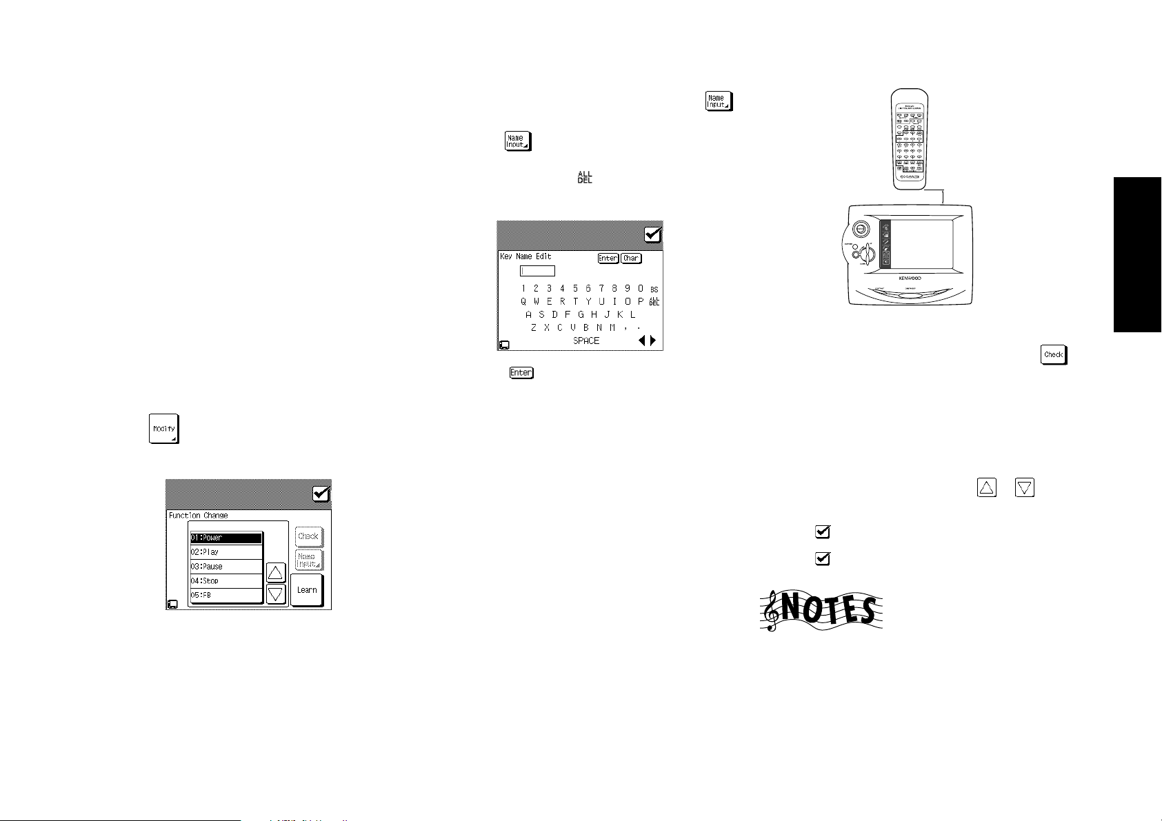
Chapter Two : Setting Up PowerTouch
What if my device does not work with any
of the codes on the list?
What if I Want PowerTouch to Control
Additional Functions?
PowerTouch contains sophisticated features that allow it to
“learn” new commands from other IR remotes. If none of
the codes for the device and brand you select work, use this
feature to instruct PowerTouch how to operate the device.
You can also use this feature to modify commands for codes
that do work or even to add extra functionality to those
codes.
For example, let’s say the basic control codes for your VCR
are Power, Play, Rewind, Fast Forward, Pause, Channel and
Record. Let’s also say that your VCR has an OSD (On Screen
Display) menu that is not part of the default code set you
chose. You can use your VCR’s remote to teach PowerTouch
to access that menu.
To teach PowerTouch new commands:
1. Follow the steps under “How Do I Identify Devices?” on
page␣ 37.
2. Touch
to open the Function Change menu:
4. When a button which can be renamed is selected,
(Name Input) button is displayed with black charac-
ters. Touch
button name (Example: CD: On). If characters already
have been enterd, touch
Do I Enter Text?” on page 8 of the Users’ Guide.)
Then touch on the keyboard display to establish
the entry.
5. Touch the Learn button.
While “Learn” is displayed, perform the next operation.
If the set is left untouched for more than one minute,
“Time Out” will be displayed.
6. Aim the device’s remote at PowerTouch and press and
hold the button on the device’s remote that corresponds
to the command you want PowerTouch to learn:
This may take a few seconds; do not move PowerTouch
or the device’s remote until PowerTouch displays the
Function Change menu again.
• “Learn Success” is displayed when learning completes
successfully.
to deisplay the keyboard and enter the
to erase them. (See “How
4 inches (10 cm)
BACKLIGHT
• “Lean Fail” is displayed when it failed.
After a learning process is completed, always touch
to test the command or function that PowerTouch has
learned. If the command or function does not work,
perform the learning process again.
Be sure to use the device’s original remote. PowerTouch
will not learn commands from other universal remotes.
7. Repeat steps 3 through 5 until you have taught
PowerTouch all the commands you want it to know. If
you need more function lines, touch
cess more lines.
8. Touch
9. Touch
to return to the IR Setup menu.
to return to the Setup menu.
or to ac-
Remote Setup
39
3. Select the button to be programmed by learning (Include “Empty 1 to Empty 8”).
You will be able to access these new commands by touching More or the button you assign on any device control
screen. (Users’ Guide)
Depending on the remote control unit, "Learn" may not
be possible.

Chapter Two : Setting Up PowerTouch
Storing Radio Stations in Memory (optional)
Your new PowerTouch provides two ways to store radio stations:
• Manual Memory, which allows you to enter and store
specific stations.
• RDS Automatic Memory (VR-4900 and KRF-V9993D),
which searches for stations broadcasting an RDS signal
and automatically stores them in the first available storage button.
Remote Setup
There are 40 preset storage buttons available.
If you have a VR-4900 or KRF-V9993D, search for and store
RDS stations first (see page␣ 41), then set stations manually.
The search function automatically assigns RDS stations to
the first storage button, overwriting any stations already
40
stored there.
You can overwrite RDS stations with manually stored sta-
tions.
Storing RDS Stations Automatically (VR-4900 and KRF-V9993D)
1. Touch (music) on the Main menu to access the
Music menu.
3. Touch to choose FM.
4. Touch
5. Touch . The receiver locates and stores any FM stations broadcasting an RDS signal. This process can take
a few minutes to complete; please be patient. While the
receiver is searching, “AUTO MEMORY” display blinks.
at the top of the screen:
Storing RDS Station Name (PS Read) (VR-4900 and KRF-V9993D)
• To execute PS Read, it is required to finish the auto
memory operation in advance.
1. Touch
menu.
2. Touch on the Music menu to access the Tuner
controls.
(music) on the Main menu to access the Music
2. Touch on the Music menu to access the Tuner
controls.
RDS stations are stored in the order they are found, up to
40 stations. If the search finds fewer than 40 stations, the
receiver may automatically store other FM stations in the
open storage buttons.
If you are repeating the RDS search, any existing preset stations (whether automatically or manually stored) will be
replaced by the results of the new search.

Chapter Two : Setting Up PowerTouch
3. Touch at the top of the screen:
4. Touch .
5. Confirm the station name list and touch
OK. If you do not want to finalize, touch
the previous screen. .
The station name are written in the preset channel list.
if it is
to return to
Storing Stations Manually
1. Touch (music) on the Quick access menu to access
the Music menu.
3. Touch to choose the receiving band.
4. Touch
tuning. Select Manual if you experience interference due
to weak radio signals.
5. Choose the station you want to store using one of the
following methods:
• Touch
quency appears.
• Touch
using the 10key pad. (e.g.; To select FM 87.5 MHz,
enter 8, 7, 5, 0, and
6. Touch Memo button at the top of the screen:
to switch between Auto tuning and Manual
or until the station’s broadcast fre-
and enter the broadcast frequency
)
7. Touch a storage button. Use or to access more
storage buttons.
If you choose a storage button that already has a station
assigned, the new station will replace the previouslystored station.
8. (Optional) Touch
in the Preset Memory menu:
• Use the stylus to select characters from the keyboard.
• Touch
again to access special characters (such as @, !, &, etc.).
Touch it a third time to return to uppercase characters.
• Touch
characters.
• Touch
entered. Touch
line.
• Touch
to access to lowercase characters. Touch it
or to move back and forth between the
(backspace) to clear the last character you
to save your title.
to enter a name for the station
to delete all the characters in the
Remote Setup
41
2. Touch on the Music menu to access the Tuner
controls.
9. Touch
turn to the Tuner controls.
10. Repeat steps 3 through 9 for each station you want to store.
Touch
menu, then touch
the basic Music menu.
to tune to the newly saved station and re-
(check icon) to return to the TUNER control
(check icon) again to return to

Chapter Two : Setting Up PowerTouch
Remote Setup
42

Chapter Three: Setting Up on the Receiver
Chapter Three: Setting Up on the Receiver
It is possible to set up the speakers and register the input
devices on the receiver main unit.
However, some of the setting items such as the controlled
device registration should also be set on the PowerTouch.
If setup is made on the PowerTouch, it is not necessary to
repeat any setup on the receiver side.
Therefore, it is recommended to perform setup on the
PowerTouch. This chapter describes the setup on the receiver
only as an alternative method in case the setup is not made
on the PowerTouch.
Do not operate the PowerTouch during the receiver setup.
Preparation for setup
Most of the receiver control keys are accommodated inside
the panel door. Make the following preparation for setup
on the receiver.
1. Plug the power cord into a household power outlet.
2. (VR-4900, VF-4700)
Press the REMOTE POWER key to turn the receiver ON.
(KRF-V9993D)
Press the POWER switch to supply the main power. The
receiver now enters the STANDBY mode (in which remote control is available). Then press the ON/STANDBY
key to turn the receiver ON.
3. Open the panel door.
VR-4900/KRF-V9993D VR-4700
Panel door
Press the DOOR OPEN/
CLOSE key to open the
panel door. To close it, press
the key again.
Panel door
Press the lower part
of the panel door.
Key layout
INPUT
CD 2/TAPE 2
A
SPEAKERS
B
MODE
MONITOR
LISTEN
MODE SET UP SOUND
Speaker setup
1. Selecting the speakers
Selecting the SUBWOOFER:
1 Press the SET UP key inside the panel door to dis-
play “SUBWOOFER OFF (or ON)”.
2 Press the MULTI CONTROL (fi/%) key to select ON
(when a subwoofer is used) or OFF (when not).
Selecting the FRONT speakers:
3 Press the SET UP key to display “FRONT LARGE (or
NORMAL)”.
4 Press the MULTI CONTROL (fi/%) key to select
FRONT LARGE (large-sized speakers) or NORMAL
(normal-sized speakers).
If the SUBWOOFER is set to OFF, the FRONT speak-
ers are set automatically to LARGE and the CENTER
speaker selection display appears automatically.
Selecting the CENTER speaker:
5 Press the SET UP key to display “CENTER LARGE
(or NORMAL or OFF)”.
6 Press the MULTI CONTROL (fi/%) key to select
CENTER LARGE (large-sized speaker), NORMAL
(normal-sized speaker) or OFF (no center speaker).
If the FRONT is set to NORMAL, the CENTER speaker
can be set to only either NORMAL or OFF.
Selecting the SURROUND speakers:
7 Press the SET UP key to display “SURROUND
LARGE (or NORMAL or OFF)”.
MULTI
fi %
CONTROL
P.CALL MEMORY AUTO BAND
fi %
8 Press the MULTI CONTROL (fi/%) key to select
SURROUND LARGE (large-sized speakers), NOR-
MAL (normal-sized speakers) or OFF (no surround
speaker).
When the FRONT is set to NORMAL, the SUR-
ROUND speakers can be set to only either NORMAL
or OFF.
Selecting SW RE-MIX:
9 Press the SET UP key to display “SW-REMIX OFF
(or ON)”. If the SUBWOOFER is set to OFF, selecting SW RE-MIX step will be skipped.
0 Press the MULTI CONTROL (fi/%) key to select ON
or OFF.
- Press the SET UP key to proceed to “Selecting the
speaker volumes” below. To exit from setting, press
the SET UP key repeatedly until “SETUP FIXED” is
displayed.
For details on the SW RE-MIX and the selection of
speakers, please see page 36.
Reveiver Setup
43

Chapter Three: Setting Up on the Receiver
Reveiver Setup
44
2. Adjusting the speaker volumes
Adjust the volume balance between the speakers in the sys-
tem by actually listening to them. See page 36 for details.
1 Minimize external noise in the listening room.
2 Position yourself in a place where you usually listen
to music or view video.
3 Increase the receiver’s main volume to -25 dB. (To
improve the adjustment accuracy, it is effective to set
the volumes at a slightly loud volume.)
4 Perform operation in step - of procedure 1 above.
The speaker volume adjustment display appears and
test noise is generated from the front left speaker (“L
0 dB” displayed). Listen to the volume of the noise
carefully.
5 When the test noise moves to the center speaker and
“C 0 dB” is displayed, adjust the volume to the same
level as the front left speaker by pressing the MULTI
CONTROL (fi/%) key.
6 Similarly, adjust the volumes of the “R” (front right),
“RS” (right surround” and “LS” (left surround) speakers.
7 Press the SET UP key to proceed to “Selecting the
speaker distances” below. To exit from setting, press
the SET UP key repeatedly until “SETUP FIXED” is
displayed.
Do not adjust the “SW” (SubWoofer) volume using
the test noise. It should be adjusted while listening
to ordinary music.
3. Setting the speaker distances
Measure the distance between each speaker and the listen-
ing position you frequently use. See page 36 for details.
1 After the operation of 7 in procedure 2 above, the
speaker distance setting display appears.
2 When “L 3.0m/10ft” is displayed, correct the dis-
tance of the front left speaker from you using the
MULTI CONTROL (fi/%) key.
3 Press SET UP key to display “C 3.0m/10ft” and
correct the distance of the center speaker from you
using the MULTI CONTROL (fi/%) key.
4 Similarly, set the distances of the “R” (front right),
“RS” (right surround), “LS” (left surround) and “SW”
(Super Woofer) speakers.
5 Press the SET UP key repeatedly until “SETUP FIXED”
is displayed.
Storing Radio Stations in Memory
(optional)
Radio stations can be preset in the memory in the receiver
and recalled by a one-touch operation.
The memory in the receiver cannot store the station names.
To store the station names, use the PowerTouch. (For details, see “Storing Radio Stations in Memory (optional)” on
page 40.)
Storing RDS Stations Automatically (VR-4900 and KRFV9993D):
1 Press the INPUT SELECTOR ¤ or ‹ key to select the
Tuner input.
2 Press the BAND key to select the FM band.
3 Press and hold the MEMORY key for more than 2 sec-
onds. The receiver locates and stores any FM stations
broadcasting an RDS signal. This process can take a few
minutes to complete; please be patient. While the receiver is searching, “AUTO MEMORY” display blinks.
Storing Stations Manually:
1 Press the INPUT SELECTOR ¤ or ‹ key to select the
Tuner input.
2 Press the BAND key to choose the receiving band.
3 Press the MEMORY key.
4 Press the P.Call (fi/%) key to display the desired preset
number.
5 Press the MEMORY key again to complete the preset-
ting.
6 To preset other stations, repeat steps 2 to 5 for each
station you want to store.

Chapter Four: Setting Up Multiple Rooms
Chapter Four: Setting Up Multiple Rooms
The VR-4900 and KRF-V9993D offers dual-room output and
control, which enables you to use a single receiver to control devices and speakers for two rooms. Due to its advanced
features and controls, you can play music in one room while
watching a movie in the other!
Depending on your tastes and budget, you can set up one
of the following “sound scenarios” to make full use of the
Receiver’s capabilities:
(Main System)
No additional amplifier for Room B: You can use the
Receiver’s Speaker B output for Room B. This allows you to
listen to full surround sound in Room A only, or in stereo
in Room A when Room B is active. The sound in Room B
will always be in stereo.
Stereo amplifier for Room B: You can use an additional
stereo amplifier for Room B (connected to the Receiver’s
Second Room Preouts). This allows you to listen to full sur-
ROOM A
TV
ROOM B
IR
RECEIVER
round sound in Room A even if you are also listening in
Room B. The sound in Room B will always be in stereo.
Multiple rooms require you to run wires and cabling from
the primary room (Room A) where your Receiver is installed
to another room (Room B) where an IR Receiver (so you
can use your PowerTouch to control devices), a second set
of speakers, and possibly a second TV/Monitor is installed:
Multiple Rooms
45
This chapter discusses some of the connection configurations and additional PowerTouch setup necessary if you want to take full advantage of the Receiver’s
multiple-room capabilities. It contains the following sections:
Making Connections page␣ 46
Setting Up PowerTouch page␣ 47
Kenwood recommends hiring a competent installer to make
multiple-room connections and setup.

Chapter Four: Setting Up Multiple Rooms
Making Connections
46
Multiple Rooms
This section describes how to connect speakers in the two
rooms to support the different scenarios. Before you read
this section, Kenwood recommends reading “Connecting
Your Speakers” on page␣ 4 of this guide. In addition, this
section discusses how to connect a second TV/Monitor and
how to connect an IR Receiver, IR Repeaters, Relays, and a
TV On/Off Sensor (for use with Perfect Macro).
Scenario 1: Surround Sound in Room A only or Stereo in Room A and Stereo in Room B (Using the Receiver’s Speaker B Outputs)
ROOM A ROOM B
RECEIVER
B
(6 – 16Ω)
LR
A
R L
LEFT
SPEAKER
RIGHT
SPEAKER
FRONT SPEAKERS
+
-
SIGNAL GND
R L
Scenario 2: Surround Sound in Room A and Stereo in Room B (Using a Stereo Amplifier in Room B)
AUDIO
VIDEO1
RECEIVER
VIDEO2
PLAY
IN
VIDEO3
PLAY
IN
VIDEO4
PLAY
IN
DVD
FRONT
SURROUND
CENTER
SUBWOOFER
DVD/6 CH. INPUT
R L
AUDIO
PRE OUT
FRONT
L
PHONO
ROOM A ROOM B
R
CD1
L
REC
OUT
R
SURROUND
MD/
TAPE1
CENTER
PLAY
IN
REC
OUT
SUB
CD2/
TAPE2
WOOFER
MONITOR
AUDIO
L
PLAY
IN
REC
OUT
R
CD-R
PLAY
VIDEO
IN
SECOND ROOM
PRE OUT
LEFT
SPEAKER
Power Amp
2-CHANNEL
POWER
AMPLIFIER
RIGHT
SPEAKER
The five amplifiers built into the receiver meet your sound
needs for both rooms. The built-in amplifiers allow you to
listen to full surround sound if you are listening in Room A
only, or stereo in Room A if both rooms are active. You will
always hear stereo in Room B. Make the speaker connections as shown in the illustration under “To Connect Front
and Surround Sound Speakers:” on page␣ 5, being sure to
also connect the Room B speakers to the SPEAKER B binding post.
You use an additional stereo amplifier for Room B. This
allows you to listen to full surround sound in Room A even
if both rooms are active. You will always hear stereo in Room
B. Make the speaker and amplifier connections as shown in
the illustration.
Both Scenarios: Connecting a Second TV/
Monitor
If you plan to watch movies, or any other visual entertainment activity in Room B, you must connect an additional
TV/Monitor. To do so, connect a standard composite video
cable from the Room B TV to the SECOND ROOM PRE
OUT VIDEO jack.
The above is possible only when the composite signals are
input.

Chapter Four: Setting Up Multiple Rooms
Setting Up the PowerTouch
You can operate equipment from two different rooms using your Kenwood PowerTouch. To do so:
1. Make sure you have identified all the connected devices
to your PowerTouch. For more information on identifying devices, see “Identifying Devices For PowerTouch
Control” on page␣ 37 of this manual.
2. Touch the
cess the Setup menu.
3. Touch to access multi-room commands:
(setup) on the Quick access menu to ac-
4. Touch the to highlight it.
5. Room A and Room B can be alternated each time the
( ) button is pressed. The but-
ton inverted in black is the currently controllable button.
Your PowerTouch is now set up to operate devices in
multiple rooms. Which room it controls depends on
which room you select. For more information on selecting rooms, see “How Do I Switch Control Modes?”
on page␣ 86 of the Users’ Guide.
Multiple Rooms
47

Chapter Four: Setting Up Multiple Rooms
Connecting an External Infrared Receiver and IR Repeaters
48
Multiple Rooms
DIGITAL OUT
DVD
CD1
MD/
TAPE1
CD-R
VIDEO2
VIDEO3
VIDEO4
OPTICAL
DIGITAL IN
COAXIAL
COMPONENT VIDEO
VIDEO
4 IN
DVD
IN
MONITOR
OUT
IR RECEIVER
IR-9991
MONITOR
S VIDEO VIDEO
Y
Cb
Cr
Y
Cb
Cr
PLAY
IN
Y
MONITOR
OUT
Cb
Cr
AC
IR-9991
ADAPTOR
IR RECEIVER
In case of use in ROOM B
MONITOR
IR IN IR IN
IR OUT
REC
OUT
VIDEO1
PLAY
IN
REC
OUT
VIDEO2
PLAY
IN
VIDEO3
PLAY
IN
VIDEO4
PLAY
IN
DVD
FRONT
SURROUND
CENTER
DVD/6 CH. INPUT
R L
AUDIO
SUBWOOFER
R L
AUDIO
SIGNAL
GND
PHONO
MONITOR
CD1
REC
OUT
TAPE1
PLAY
REC
OUT
TAPE2
PLAY
REC
OUT
CD-R
PLAY
PRE OUT
MD/
IN
CD2/
IN
IN
SECOND ROOM
PRE OUT
FRONT
L
R
L
R
SURROUND
CENTER
SUB
WOOFER
AUDIO
L
R
VIDEO
RF REMOTE ANTENNA
SYSTEM
CONTROL
SL 16
TEXT
ANTENNA
RECEIVER
DC12V 20mA
FM 75Ω
IR
IN
GND
B
IR OUT
REMOTE
IR
REPEATER
OUT
AM
A
IR OUT LCD IR RECEIVER IN
RELAY
TV ON/OFF
DC12V 20mA
REMOTE
CONTROL
SENSOR
LCD
SURROUND SPEAKERS
DC12V
DC5V
(6 – 16Ω) (6 – 16Ω)
20mA
10mA
R L
FRONT SPEAKERS
B
(6 – 16Ω)
LR
CENTER SPEAKERS
C
+
-
A
R L
AC 120V 60Hz
SWITCHD TOTAL
90W 0.75A MAX
AC 220 –
240V
AC 110 –
120V
+
-
AC
ADAPTOR
IR OUT
Note:
The optional IR-9991 IR-repeater is not being sold in Europe.
IR
REPEATER

Chapter Four: Setting Up Multiple Rooms
Connecting an External Infrared Receiver and IR Repeaters, continued
Your new audio-video receiver supports the IR-9991 twoway external infrared (IR) remote transceiver control. The
IR-9991 enables you to use the Receiver’s PowerTouch to
operate the receiver if it is:
• in a stereo closet/cabinet
• behind glass doors
• in another room
• in any situation where the device to be controlled is not
visible
You can substitute Xantech (291-80, 480-30, or 490-30 series) IR receivers for the IR-9991. However, these devices are
one-way only, and will not supply system status feedback
to PowerTouch.
For more information about using external IR receivers in
another room, see “Chapter Four: Setting Up Multiple
Rooms” on page␣ 45.
To Connect a KENWOOD IR-9991 IR
Receiver:
1. Connect the IR-9991’s IR IN cable to the Receiver’s IR
RECEIVER IN jack. This jack supports a 12V 20mA sig-
nal.
2. Connect the IR-9991’s IR OUT cable to the Receiver’s IR
OUT LCD REMOTE jack.
3. Connect an AC adaptor to the IR-9991. Do not plug the
adaptor into the wall until all connections are made.
4. To activate the IR receiver connections, you need to press
INPUT MODE key on the front panel of the receiver for
more than 2 seconds.
You will see “RF OFF” (VR-4900/VR-4700) or “DATA
REAR IN” (KRF-V9993D)
• The RF remote function will not be available in RF
OFF mode.
To Connect any other IR Receiver:
1. Connect the IR receiver’s output cable to the Receiver’s
IR RECEIVER IN jack. This jack supports a 12V 20mA
signal.
2. (For some IR receiver)
Connect an AC adaptor to the IR receiver. Do not plug
the adaptor into the wall until all connections are made.
3. To activate the IR receiver connections, you need to press
INPUT MODE key on the front panel of the receiver for
more than 2 seconds.
• VR-4900/VR-4700 : You will see “RF OFF” on the
receiver display.
• KRF-V9993D : You will see “DATA REAR IN ” on
the receiver display.
To Connect IR Repeaters:
IR repeaters enable you to control components located in
cabinets or behind glass doors. To connect repeaters:
1. Connect the IR repeater to the device as described in the
repeater’s manual.
2. Connect the IR repeater cable(s) to the Receiver’s IR RE-
PEATER OUT jack(s).
IR repeaters send a signal similar to the device’s own remote control. Xantech repeaters (models 282-00, 286-00,
or 283-00) are compatible with your new audio-video receiver.
Do not connect IR repeaters unless you have connected an
external IR receiver. The connections are only active when
an IR receiver is connected.
Multiple Rooms
49

Chapter Four: Setting Up Multiple Rooms
Connecting and Setting Up On/Off Sensors or Relay Controls (VR-4900 and KRF-V9993D)
50
Multiple Rooms
DIGITAL OUT
DVD
CD1
MD/
TAPE1
CD-R
VIDEO2
VIDEO3
VIDEO4
OPTICAL
DIGITAL IN
COAXIAL
COMPONENT VIDEO
Y
Cb
VIDEO
Cr
4 IN
DVD
IN
Y
Cb
Cr
MONITOR
OUT
Y
Cb
Cr
S VIDEO VIDEO
PLAY
PLAY
PLAY
PLAY
IN
MONITOR
OUT
SURROUND
RELAY
CONTROL
REC
OUT
VIDEO1
IN
REC
OUT
VIDEO2
IN
VIDEO3
PLAY
IN
VIDEO4
IN
DVD
FRONT
CENTER
DVD/6 CH. INPUT
R L
AUDIO
SUBWOOFER
R L
AUDIO
SIGNAL
GND
PHONO
CD1
TAPE1
MONITOR
CD-R
PRE OUT
REC
OUT
MD/
PLAY
IN
REC
OUT
CD2/
TAPE2
PLAY
IN
REC
OUT
PLAY
IN
SECOND ROOM
PRE OUT
FRONT
L
R
L
R
SURROUND
CENTER
SUB
WOOFER
AUDIO
L
R
VIDEO
RF REMOTE ANTENNA
SYSTEM
CONTROL
SL 16
TEXT
FM 75Ω
ANTENNA
IR
RECEIVER
IN
DC12V 20mA
GND
B
IR OUT
LCD
REMOTE
AM
RELAY
CONTROL
DC12V
20mA
TV ON/OFF
SENSOR
DC5V
10mA
IR
REPEATER
OUT
A
IR OUT LCD IR RECEIVER IN
DC12V 20mA
REMOTE
SURROUND SPEAKERS
(6 – 16Ω) (6 – 16Ω)
R L
FRONT SPEAKERS
B
(6 – 16Ω)
LR
CENTER SPEAKERS
C
R L
+
-
A
AC 120V 60Hz
SWITCHD TOTAL
90W 0.75A MAX
AC 220 –
240V
AC 110 –
120V
+
-
CONTROLLED
DEVICE
(e.g. Powered Screen)
status
Power On
and when
Power
Off
Power
On
switched to
Video Input
To Tip 0V 0V +12V
To Ring 0V +12V +12V
To Sleeve Ground Ground Ground
TV ON/OFF
SENSOR

Chapter Four: Setting Up Multiple Rooms
Connecting and Setting Up On/Off Sensors or Relay Controls (VR-4900 and KRF-V9993D), continued
The VR-4900 and KRF-V9993D supports 2 types of additional external controls:
• A relay control that enables you to operate external relay-control devices (such as the Xantech 590-0 programmable controller, via Xantech’s 599-00 pulse switching
module).
• A TV ON/OFF sensor that enables you to use the Perfect
Macro feature (described further in the Users’ Guide) to
accurately sense whether the TV is already on or off and
adjust accordingly.
To Connect Relay Controls:
1. Consult the relay control’s manual for compatibility information and installation instructions before connecting it to your new receiver. If you install the control incorrectly or connect an incompatible control to the receiver, you may damage the control and your new receiver.
2. Connect the control cable to the receiver’s RELAY CON-
TROL jack. This jack supports a 12V, 20mA signal.
Do not connect multiple 599-00 switching modules to each
other or to the receiver, as this can exceed the maximum
current capacity of the jack and damage your receiver.
To Connect TV ON/OFF Sensors:
1. Connect the sensor to the TV as described in the sensor’s
manual.
2. Connect the sensor cable to the receiver’s TV ON/ OFF
SENSOR jack. This jack supports a 5V, 10mA signal.
JDS:PSS-TV or NILES:LS-1, APC-2 sensors are compatible
with your new receiver.
Multiple Rooms
51

Chapter Five : Warnings and Specifications
Chapter Five: Warnings and Specifications
Read this page carefully to ensure safe operation.
Warnings
FCC WARNING
This equipment may generate or use radio frequency energy. Changes or modifications to this equipment may cause
harmful interference unless the modifications are expressly
approved in the instruction manual. The user could lose
the authority to operate this equipment if an unauthorized
change or modification is made.
NOTE: This equipment has been tested and found to comply with the limits for a Class B digital device, pursuant to
Part 15 of the FCC Rules. These limits are designed to provide reasonable protection against harmful interference in
a residential installation. This equipment may cause harmful interference to radio communications if it is not installed
and used in accordance with the instructions. However, there
is no guarantee that interference will not occur in a particu-
52
lar installation. If this equipment does cause harmful interference to radio or television reception, which can be determined by turning the equipment off and on, the user is
encouraged to try to correct the interference by one or more
of the following measures:
• Reorient or relocate the receiving antenna.
• Increase the separation between the equipment and the
receiver.
• Connect the equipment into an outlet on a circuit different from the one that the receiver is connected to.
• Consult the dealer or an experienced radio/TV technician for help.
FCC Compliance Notice
Specifications
Audio-video Receiver, VR-4900 and VR-4700
These devices comply with Part 15 of FCC Rules.
Operation is subject to the following two conditions:
(1) This device may not cause harmful interference, and
(2) this device must accept any interference received, including interference that may cause undesired operation.
KENWOOD U.S.A. CORPORATION
2201 East Dominguez St., Long Beach, CA 90801-5745
Telephone: 310-639-9000
IC(Industry Canada) Notice
Operation is subject to the following two conditions: (1)
This device may not cause interference, and (2) this device
must accept any interference, including interference that may
cause undesired operation of the device.
Note to CATV System Installer:
This reminder is provided to call the CATV system installer’s
attention to Article 820-40 of the NEC that provides guidelines for proper grounding and, in particular, specifies that
the cable ground shall be connected to the grounding system of the building, as close to the point of cable entry as
practical.
NOTE: Do not use contact cleaning agents because they
could cause a malfunction. Be especially careful not to use
contact cleaning agents containing oil, since they may deform the plastic components.
VR-4900
Specifications
Audio Section
Rated Output Power during stereo operation
130 watts per channel minimum RMS, both channels
driven, at 6 Ω from 20 Hz to 20 kHz with no more than
0.03% total harmonic distortion (FTC).
Effective Output Power during surround operation
(Simultaneous power)
Front
20 Hz to 20 kHz, 0.06 % T.H.D. at 6 Ω........ 130 W + 130 W
Center
20 Hz to 20 kHz, 0.06 % T.H.D. at 6 Ω........................ 130 W
Surround
20 Hz to 20 kHz, 0.06 % T.H.D. at 6 Ω........ 130 W + 130 W
Total Harmonic Distortion ............. 0.005 % (1 kHz, 10 W, 6 Ω)
Frequency Response (IHF’66)
CD1 .............................................. 7 Hz ~ 90 kHz, 0 dB, -3 dB
DVD 6CH ................................... 7 Hz ~ 100 kHz, 0 dB, -3 dB
Signal to Noise Ratio (IHF ‘66)
PHONO (MM) ............................................................... 74 dB
CD1 .................................................................................. 97 dB
Input Sensitivity / Impedance
PHONO (MM) ................................................ 2.5 mV / 47 kΩ
CD1 .................................................................200 mV / 47 kΩ
DVD 6CH ........................................................200 mV / 47 kΩ
Output Level / Impedance
TAPE REC ..................................................... 200 mV / 2.2 k Ω
PRE OUT (Front, Center, Surround, Subwoofer) .. 1 V / 1 kΩ
Tone Control
Bass ............................................................
Treble .........................................................
Loudness Control
Volume at -30 dB level ....... +6 dB (100 Hz), +3 dB (10 kHz)
+ 7 dB (at 100 Hz)
+ 7 dB (at 10 kHz)
Digital Audio Section
Sampling Frequency............. 32 kHz, 44.1 kHz, 48 kHz, 96 kHz
Input Level / Impedance / Wavelength
Optical ........................ -15 dBm ~ -21 dBm, 660 nm
Coaxial ............................................................ 0.5 Vp-p / 75 Ω
Output Level / Impedance / Wavelength
Optical ........................ -15 dBm ~ -21 dBm, 660 nm
Coaxial ............................................................ 0.5 Vp-p / 75 Ω
+30 nm
+30 nm

Chapter Five : Warnings and Specifications
KRF-V9993D
Audio Section
Rated Output Power during stereo operation
20 Hz ~ 20 kHz, 0.05% T.H.D. , 4Ω (IEC)
.......................................................................... 130W + 130 W
1 kHz, 0.05% T.H.D. , 4Ω (DIN/IEC) ........... 130W + 130 W
Effective Output Power during surround operation
(Simultaneous power)
Front
20 Hz ~ 20 kHz, 0.06 % T.H.D. at 4 Ω ......... 130 W + 130 W
Center
20 Hz ~ 20 kHz, 0.06 % T.H.D. at 4 Ω ......................... 130 W
Surround
20 Hz ~ 20 kHz, 0.06 % T.H.D. at 4 Ω ......... 130 W + 130 W
Total Harmonic Distortion ............. 0.005 % (1 kHz, 10 W, 4 Ω)
Frequency Response (IHF’66)
CD1 .............................................. 7 Hz ~ 90 kHz, 0 dB, -3 dB
DVD 6CH ................................... 7 Hz ~ 100 kHz, 0 dB, -3 dB
Signal to Noise Ratio (IHF ‘66)
PHONO (MM) ............................................................... 74 dB
CD1 .................................................................................. 97 dB
Input Sensitivity / Impedance
PHONO (MM) ................................................ 2.5 mV / 47 kΩ
CD1 ................................................................. 200 mV / 47 kΩ
DVD 6CH ........................................................200 mV / 47 kΩ
Output Level / Impedance
TAPE REC .......................................................200 mV / 2.2 kΩ
PRE OUT(Front, Center, Surround, Subwoofer) ...1 V / 1 kΩ
Tone Control
Bass ............................................................
Treble .........................................................
Loudness Control Volume at -40 dB level
............................................. +6 dB (100 Hz), +3 dB (10 kHz)
Digital Audio Section
Sampling Frequency............. 32 kHz, 44.1 kHz, 48 kHz, 96 kHz
Input Level / Impedance / Wavelength
Optical ........................ -15 dBm ~ -21 dBm, 660 nm
Coaxial ............................................................ 0.5 Vp-p / 75 Ω
Output Level / Impedance / Wavelength
Optical ........................ -15 dBm ~ -21 dBm, 660 nm +30 nm
Coaxial ............................................................ 0.5 Vp-p / 75 Ω
+ 7 dB (at 100 Hz)
+ 7 dB (at 10 kHz)
+30 nm
Video Section
Video Inputs / Outputs
Video (composite) .............................................1 Vp-p / 75 Ω
S Video ( luminance signal) ..............................1 Vp-p / 75 Ω
(chrominance signal) .................. 0.286 Vp-p / 75 Ω
Component (luminance signal) ....................... 1 Vp-p / 75 Ω
(Cb/Cr-signal) ............................ ±0.350 Vp-p / 75 Ω
FM Tuner Section
Tuning Frequency Range........................... 87.5 MHz ~ 108 MHz
Usable Sensitivity (DIN at 75 Ω)
Mono .................. 1.2 µV/ 13.2 dBf (40 kHz dev., S/N 26 dB)
Stereo ................... 45 µV/ 44.2 dBf (46 kHz dev., S/N 46 dB)
Total Harmonic Distortion (1 kHz)
Mono ................................................... 0.2 % (65.2 dBf input)
Stereo ................................................... 0.8 % (65.2 dBf input)
Signal to Noise Ratio (DIN. at 1 kHz, 40 kHz dev.)
Mono ................................................... 65 dB (65.2 dBf input)
Stereo ................................................... 60 dB (65.2 dBf input)
Stereo Separation (1 kHz) ................................................. 36 dB
Selectivity (DIN +300 kHz) ............................................... 64 dB
Frequency Response ................ 30 Hz ~ 15 kHz, +0.5 dB, -3.0 dB
AM Tuner Section
Tuning Frequency Range ........................... 531 kHz ~ 1,602 kHz
Usable Sensitivity (30 % mod., S/N 20 dB)
........................................................................... 16 µV / (600 µV/m)
Signal to Noise Ratio (30 % mod., 1 mV input) .............. 50 dB
IR In/Out Section
IR Receiver In Terminal
Maximum Output Current ............................................ 20 mA
Operating Voltage.............................................................. 12 V
Output Impedance ..........................................................470 Ω
IR Out LCD Remote Terminal
Maximum Output Current ............................................ 20 mA
Operating Voltage................................................................ 5 V
Output Impedance ..........................................................470 Ω
SHAPE OF PLUG TO BE CONNECTED:
IR Receiver In and IR Out
LCD Remote
Stereo mini plug Mono mini plug
Sleeve
Tip
Ring
IR IN/OUT SPECIFICATION:
IR Receiver In
To Tip Signal Signal
To Ring Ground
To Sleeve +12V Ground
RELAY CONTROL SPECIFICATION:
Power
Off
To Tip 0V 0V +12V
To Ring 0V +12V +12V
To Sleeve Ground Ground Ground
IR Repeater Out
Terminal
status
Power
On
Sleeve
Tip
IR OUT LCD
REMOTE
Power On
and when
switched to
Video Input
General
Power consumption .......................................................... 480 W
AC outlet
Switched ................................................... 2 (total 90 W max.)
Dimensions.................................................................. W : 480mm
Weight (Net)........................................................................ 18 kg
H : 191mm
D : 416mm
53
Specifications
Kenwood follows a policy of continuous advancements in development. For this reason, specifications may be changed without notice. Full performance may not be exhibited in
extremely cold locations (below 0 deg. C).

54
Index
Numerics
200-Disc CD Changer
connecting ................................................ 15
connecting SL16 text cable ...................... 15
identifying to PowerTouch ...................... 38
SL16/XS8 switch....................................... 15
A
AM antenna
connecting .................................................31
preventing hum interference ....................31
amplifier
connecting .................................................. 6
using in multiple rooms .......................... 46
analog cables
DVD player ............................................... 17
laser disc player .................................. 25,␣ 27
antennas, connecting......................................... 31
audio cables
200-Disc CD Changer .............................. 15
cable TV ..................................................... 11
camcorder ................................................. 29
DVD player ............................................... 17
laser disc player (AC-3 Output) .............. 25
laser disc player (no AC-3 Output) ......... 27
MD recorder .............................................. 21
primary tape deck .....................................21
satellite tuner ............................................. 11
second tape deck ...................................... 23
VCR ..................................................... 13,␣ 29
B
batteries, installing in PowerTouch ................. 32
C
cable radio, connecting (call provider) ............ 31
cable TV
connecting ........................................... 10,␣ 11
identifying to PowerTouch ...................... 38
with RCA video output .............................11
without RCA video output ....................... 11
camcorder, connecting ..................................... 29
CD player, connecting ................................ 14,␣ 15
CD-R Recorder, connecting ........................ 18,␣ 19
CD2/TAPE2, setting the input icon ................. 38
center speaker, connecting ................................. 5
clearing PowerTouch stored settings ................ 33
coaxial cable
200-Disc CD Changer .............................. 15
DVD player ............................................... 17
LD player ............................................ 25, 27
communication cable, connecting .................. 14
connecting
200-Disc CD Changer .............................. 15
AM antenna ...............................................31
amplifier ..................................................... 6
antennas .................................................... 31
audio cable to MD recorder .................... 21
audio cables to VCR ................................ 13
cable radio (call provider) ........................31
camcorder ................................................. 29
CD player............................................ 14,␣ 15
CD-R Recorder ................................... 18,␣ 19
DVD player ......................................... 16,␣ 17
external infrared receiver ................... 48,␣ 49
FM antenna ............................................... 31
IR repeaters ......................................... 48, 49
laser disc player with AC-3 Output ......... 24
MD recorder ............................................. 20
On/Off sensors ................................... 50, 51
other primary CD player ......................... 15
primary tape deck .................................... 20
relay controls ...................................... 48, 49
second VCR .............................................. 13
speakers ...................................................... 4
speakers multiple rooms ................... 45, 46
system control cable to primary
tape deck ............................................... 21
tape deck ................................................... 20
turntable/record player ............................ 28
turntable’s ground cable to receiver ........ 28
TV .......................................................... 8,␣ 46
TV On/Off sensors ............................. 50, 51
VCR ..................................................... 12, 29
video cables to VCR ................................. 13
video-CD compatible CD player............. 15
connection warning
analog cables, laser disc player................ 25
DVD player ............................................... 17
IR repeaters ............................................... 49
laser disc player .................................. 25, 27
receiver vs. relay controls .......................... 51
second CD player ..................................... 22
second tape deck ...................................... 22
D
deleting, PowerTouch setup codes ................... 38
devices
identifying to PowerTouch ...................... 37
digital cable
CD player.................................................. 15
CD-R Recorder ......................................... 19
DVD player ............................................... 17
laser disc player (AC-3 Output) .............. 25
laser disc player (no AC-3 Output) ......... 27
digital connection warning .............................. 25
Dolby Digital (AC-3) RF Out ........................... 25
DVD player
connecting .......................................... 16,␣ 17
identifying to PowerTouch ...................... 38
E
external infrared receiver, connecting........ 48, 49
F
FM antenna, connecting ....................................31
front speakers, connecting ................................. 5
G
ground cable, connecting turntable................. 28
H
hum interference ...............................................31
I
IR receiver
connecting ................................................ 49
models compatible with receiver ............ 49
IR repeaters
connecting ................................................ 49
models compatible with receiver ............ 49
L
laser disc player
identifying to PowerTouch ...................... 38
RF Demodulator and ............................... 25
with AC-3 Output, connecting ................ 25
with PCM Digital Output, connecting.... 27
without AC-3 Output, connecting .......... 27
without Dolby Digital Output,
connecting ............................................ 27
left speakers
front, connecting ........................................ 5
surround, connecting................................. 5
M
MD recorder, connecting.................................. 20
multiple rooms
connecting IR repeaters .......................... 49
connecting relays....................................... 51
connecting second TV monitor ............... 46
connecting TV On/Off sensor .................. 51
IR receiver, connecting............................. 49
set up ........................................................ 47
sound scenarios.................................. 45, 46
sound setup .............................................. 47
using external infrared receiver ............... 49
N
navigating PowerTouch interface ..................... 34
O
On/Off sensors, connecting .............................. 51
optical cable
DVD player ............................................... 17
MD recorder .............................................. 21
P
PCM Digital Output laser disc player,
connecting..................................................... 27
powered subwoofer, connecting ........................ 5
PowerTouch
clearing stored settings and
reconfiguring ........................................ 33
deleting setup code .................................. 38
identifying devices ................................... 37
identifying receiver model type............... 33
installing batteries.................................... 32
introductory information ........................ 32
navigating the display screen .................. 34
operating components through
external infrared receiver ..................... 49
replacing old setup code with new ......... 38
selecting main menu ............................... 34
selecting model type ................................ 33
selecting speakers ..................................... 35
setup for multiple room use.................... 47
setup menu ............................................... 35

speaker distance, setting .......................... 36
speaker level, setting ................................ 36
speaker type, setting ................................. 37
storing radio stations ............................... 40
R
radio stations, storing in memory ................... 40
RDS stations, storing in PowerTouch .............. 40
receiver
identifying model type to PowerTouch .. 33
record player/turntable, connecting ................ 28
relay controls
connecting .......................................... 50, 51
connection warning ..................................51
resetting
PowerTouch .............................................. 33
RF remote antenna ............................................ 31
RF remote control function .............................. 42
right speakers
front, connecting ........................................ 5
surround, connecting ................................. 5
room A
sound scenario ........................................ 45, 46
room B
connecting second TV .................................. 46
sound scenario ........................................ 45, 46
S
S video cable
cable TV ..................................................... 10
DVD player ............................................... 16
laser disc player .................................. 24,␣ 26
satellite tuner ............................................. 10
VCR ........................................................... 12
satellite tuner
connecting ........................................... 10,␣ 11
identifying to PowerTouch ...................... 38
second tape deck
connecting .................................................21
connecting audio cable ............................. 21
connection warning ................................. 23
identifying to PowerTouch ...................... 38
second VCR
connecting .......................................... 13, 29
identifying to PowerTouch ...................... 38
setup codes
deleting ..................................................... 38
setup menu, on PowerTouch ........................... 35
SL16
200-Disc CD Changer .............................. 15
chained connections ................................ 30
system control mode ............................... 30
XS8 switch, 200-Disc CD Changer.......... 15
sound scenarios
Room A ............................................... 45, 46
Room B ............................................... 45, 46
speakers
connecting ............................................ 4,␣ 45
connecting in multiple rooms ................ 45
setting with PowerTouch ......................... 35
specifications and warnings ............................. 52
storing radio stations in memory .................... 40
subwoofer
connecting .................................................. 4
supplemental power amplifiers, connecting..... 7
surround sound
connecting speakers ................................... 5
system control cables
200-Disc CD Changer .............................. 15
CD player.................................................. 15
connection warning ................................. 30
MD recorder ............................................. 20
tape deck ................................................... 20
system control chaining ................................... 30
T
tape deck
connecting ................................................ 20
identifying to PowerTouch ...................... 38
turntable/record player, connecting ................ 28
TV
connecting .................................................. 9
identifying to PowerTouch ...................... 38
On/Off sensors, connecting ..................... 51
watching without using receiver ............... 9
V
VCR
connecting .......................................... 12,␣ 13
identifying to PowerTouch ...................... 38
video cables
another VCR ............................................. 29
cable TV ..................................................... 11
camcorder ................................................. 29
DVD player ............................................... 17
laser disc player (AC-3 Output) .............. 25
laser disc player (no AC-3 Output) ......... 27
satellite tuner ............................................. 11
TV ................................................................ 9
VCR ........................................................... 13
video CD-compatible CD player, connecting . 15
W
warnings and specifications ............................. 52
X
XS8 chained connections, example of
chained components .................................... 30
55
Index

56
Index
For your records
Record the serial number, found on the back of the unit, in the spaces designated
on the warranty card, and the space provided below. Refer to the model and
serial numbers whenever you call upon your dealer for information or service on
this product.
Model Serial Number
 Loading...