

Page 1

INSTRUCTION MANUAL
INTERACTIVE VISUAL COMMUNICATOR
VC-H1
KENWOOD CORPORATION
© B62-0974-10 (K)
09 08 07 06 05 04 03 02 01
Page 2

NOTICES TO THE USER
One or more of the following statements may be
applicable:
FCC WARNING
This equipment generates or uses radio frequency energy. Changes
or modifications to this equipment may cause harmful interference
unless the modifications are expressly approved in the instruction
manual. The user could lose the authority to operate this equipment if
an unauthorized change or modification is made.
INFORMATION TO THE DIGITAL DEVICE USER REQUIRED BY
THE FCC
This equipment has been tested and found to comply with the limits
for a Class B digital device, pursuant to Part 15 of the FCC Rules.
These limits are designed to provide reasonable protection against
harmful interference in a residential installation.
This equipment generates, uses and can generate radio frequency
energy and, if not installed and used in accordance with the
instructions, may cause harmful interference to radio communications.
However, there is no guarantee that the interference will not occur in a
particular installation. If this equipment does cause harmful
interference to radio or television reception, which can be determined
by turning the equipment off and on, the user is encouraged to try to
correct the interference by one or more of the following measures:
•
Reorient or relocate the receiving antenna.
•
Increase the separation between the equipment and receiver.
•
Connect the equipment to an outlet on a circuit different from that to
which the receiver is connected.
•
Consult the dealer for technical assistance.
Page 3

THANK YOU!
SUPPLIED ACCESSORIES
Thank you very much for purchasing this Interactive
Visual Communicator. It was designed for plug-and-play
color slow-scan television (SSTV). This portable unit
includes a slow-scan converter, CCD camera, and LCD
monitor. You can enjoy SSTV anywhere just by making
a single connection with your amateur radio.
KENWOOD believes that this product will provide more
fun in your outdoor ham activities.
FEA TURES
This Communicator has the following main features:
• Includes all equipment required for SSTV;
a slow-scan converter, CCD color camera, and LCD
color monitor.
• Can store up to 10 images in memory. You may
select the best image to send, from those images.
• Functions as a speaker microphone of a handy
transceiver.
• Compatible with 8 popular SSTV modes besides the
newly developed Fast FM mode.
• Equipped with a video input terminal to take in
images from a digital camera or 8 mm VTR.
Check that everything listed below is included in your
package.
yrosseccA rebmuNtraP ytitnauQ
elbacnoitcennoCXX-1033-03E1
retpadaCAXX-9550-80W1
partSXX-4430-96J1
htolCXX-9340-10W1
dracytnarraW—1
launamnoitcurtsnIXX-4790-26B1
i
Page 4

CONTENTS
PRECAUTIONS......................................................... 1
CONVENTIONS FOLLOWED IN THIS MANUAL....... 1
GETTING ACQUAINTED 2
ORIENTATION........................................................... 2
CONNECTOR DESCRIPTIONS ................................ 2
PREPARATION 3
INSTALLING AL KAL INE BA T TE RIE S ........................ 3
ATTACHING THE STRAP ..........................................4
CONNECTING THE AC ADAPTER ........................... 4
CONNECTION WITH A HANDY TRANSCEIVER ...... 5
REMOVING/ REINST ALLING THE CAMERA UNIT... 5
QUICK USE 6
OPERATING BASICS 7
SWITCHING POWER ON/OFF ................................. 7
SELECTING A SSTV MODE......................................7
CAPTURING IMAGES............................................... 8
TRANSMITTING IMAGES ......................................... 9
RECEIVING IMAGES .............................................. 10
AUXILIARY FUNCTIONS 11
MEMORY PROTECTION ........................................ 11
BATTERY SAV E R.................................................... 11
SUPERIMPOSING A CALL SIGN ............................ 12
AUTO TRANSMIT ................................................... 13
AF MUT I N G.............................................................13
DISPLAY CONTRAST CHANGE ............................. 13
MAINTENANCE 14
GENERAL INFORMATION...................................... 14
SERVICE.................................................................14
SERV I C E N OTE...................................................... 14
CLEANING .............................................................. 14
TROUBLESHOOTING............................................. 15
APPENDIX 16
VC-H1 D ATA PORT PI N F U N C T I O N S.................... 16
CONNECTION DIAGRAM WITH TS-570
OR TS-870 .............................................................. 16
COMPUTER CONTROL.......................................... 17
SPECIFICATIONS 19
MEMORY RESET.................................................... 11
ii
Page 5

PRECAUTIONS
CONVENTIONS FOLLOWED IN THIS MANUAL
Please observe the following precautions to prevent fire,
personal injury, or product damage:
• Never open this product. You will get an electric
shock if you touch the circuit on which high voltage is
applied.
• Do not install batteries in a hazardous environment
where sparks could cause an explosion.
• Never discard old batteries in fire because extremely
high temperatures can cause batteries to explode.
• Do not modify this product unless instructed by
KENWOOD documentation.
• Do not apply excessive force to the monitor display.
• Do not expose this product to long periods of direct
sunlight nor place it close to heating appliances.
• Do not place this product in excessively dusty areas,
humid areas, wet areas, nor on unstable surfaces.
• If an abnormal odor or smoke is detected coming
from this product, turn OFF the power immediately
and remove the batteries from the product. When
using AC power, also remove the AC adapter from an
AC outlet. Contact your authorized KENWOOD
dealer, customer service, or service station.
The writing conventions described below have been
followed to simplify instructions and avoid unnecessary
repetition.
noitcurtsnI oDottahW
sserP ]YEK[ .esaelerdnasserP YEK .
sserP ]2YEK[+]1YEK[ .
sserP
NOREWOP+]YEK[ .
sserP +]2YEK[+]1YEK[
NOREWOP .
Note: Pressing the same key again immediately after pressing [KEY]+
POWER ON causes the setting to be changed back.
sserp 2YEK .
2YEK ehtedilsneht, RWP
dlohdnasserP 1YEK neht,
,FFOrewop1H-CVhtiW
dlohdnasserp YEK neht,
ehtedils RWP .drawpuhctiws
,FFOrewop1H-CVhtiW
dlohdnasserp 1YEK dna
.drawpuhctiws
1
Page 6

GETTING ACQUAINTED
ORIENTATION CONNECTOR DESCRIPTIONS
qq
q Video input jack
qq
This jack accepts a 3.5 mm (1/8") diameter,
CCD
camera
LCD
monitor
Speaker/
microphone
COM jack
Video
output jack
DC IN jack
3-conductor plug. You may connect a digital camera
or 8 mm VTR to take in images (acceptable video
signals: 75 Ω, 1 V
Ground
ww
w COM jack
ww
Video
signal
(140 IRE) ±15%, NTSC).
P-P
No Connection
Connect a personal computer in which a dedicated
program has been installed. For details, contact your
authorized KENWOOD dealer, customer service, or
service center.
ee
e Video output jack
ee
Connect an external monitor, if you prefer. This jack
accepts a 2.5 mm (1/10") diameter, 2-conductor plug.
1
When connecting a device
other than the provided
1
camera unit, using this
conductor could cause the
device to be damaged.
DATA port
Video input jack
rr
r DC IN jack
rr
Ground Video
signal
Connect the provided AC adapter to use power
supplied from an AC outlet.
tt
t DATA port
tt
Connect your transceiver. See page 5.
2
Page 7

PREPARATION
INSTALLING ALKALINE BATTERIES
WARNING!
◆
DO NOT INST ALL THE BATTERIES IN A HAZARDOUS
ENVIRONMENT WHERE SPARKS COULD CAUSE AN
EXPLOSION.
◆
NEVER DISCARD OLD BATTERIES IN FIRE BECAUSE
EXTREMELY HIGH TEMPERATURES CAN CAUSE BATTERIES
TO EXPLODE.
1 To remove the battery cover, slide the cover outward
while slightly pushing on the grooves on the cover.
Grooves
2 Insert four AA (LR6) alkaline batteries.
• Be sure to match the battery polarities with those
marked on the VC-H1.
3 Align the three tabs on the battery cover, then slide
the cover inward until the center tab clicks.
Center tab
Note:
◆
It is strongly recommended to use high quality alkaline batteries
rather than manganese batteries, to enjoy longer periods of battery
life. Do not use commercially available NiCd batteries.
◆
If you will not use the VC-H1 for a long period, remove the batteries
from the VC-H1.
◆
Do not use different kinds of batteries together .
◆
When the battery voltage is low, replace all four old batteries with
new ones.
The approximate lives of alkaline batteries depending on
the operation status are shown below:
NOaremaCsetunim05
)dellaceryromem(NOrotinoMsruoh2
FFOrotinoMsruoh6
When the batteries become almost empty while the
TX/RX indicator is green, the indicator starts blinking.
Replace the batteries at that time. This function,
however, does not operate while Fast FM mode is
currently selected.
3
Page 8
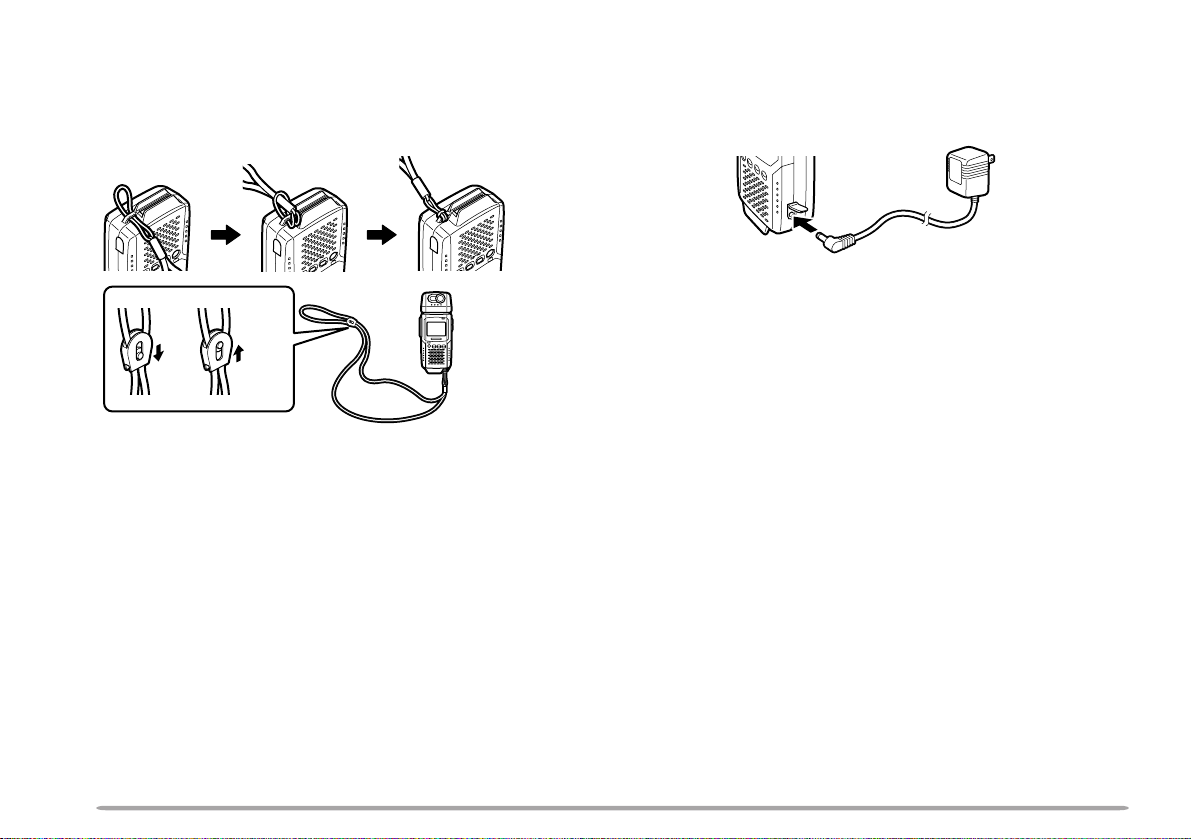
ATTACHING THE STRAP
CONNECTING THE AC ADAPTER
If you want, attach the provided strap to the bottom of
the VC-H1. The strap can be used to hang the VC-H1
around your neck.
UnlockLock
Use the provided AC adapter to connect the VC-H1 to an
AC outlet if you want to use AC power.
WARNING!
◆
USING AN AC ADAPTER OTHER THAN THE PROVIDED
ADAPTER CAN CAUSE FIRE OR PRODUCT DAMAGE.
◆
DO NOT USE AN EXTENSION CABLE UNLESS ABSOLUTELY
NECESSARY. IMPROPER EXTENSION CABLES CAN CAUSE
FIRE OR ELECTRIC SHOCK.
Note: The provided AC adapter does not function as a battery charger.
4
Page 9

CONNECTION WITH A HANDY TRANSCEIVER
REMOVING/ REINSTALLING THE CAMERA UNIT
Use the provided cable to connect the VC-H1 with a
handy transceiver.
Note: The VC-H1 functions as a speaker microphone only when
connected with a handy transceiver. You need not switch ON the VC-H1.
1 Confirm that the power switches of both the VC-H1
and transceiver are OFF.
2 Connect the appropriate end of the provided cable to
the DATA port of the VC-H1.
• To remove the cable from the VC-H1, pull the cable
connector downward while pushing its tabs from both
sides.
To remove
3 Connect the other end of the cable to the speaker/
microphone jacks on your handy transceiver.
Note: The compatible handy transceivers are TH-26, TH-46, TH-27,
TH-47, TH-28, TH-48, TH-22, TH-42, TH-77, TH-78, TH-79, and TH-G71.
An optional PG-4T cable is available for connecting with a TM-255,
TM-455, TM-733, TM-V7, or TM-G707 transceiver. To make a cable for
connecting with a TS-570 or TS-870 transceiver , you may obtain an
optional connector kit (E59-0407-08) which mates with the VC-H1 DA TA
port. For the above options, contact your authorized KENWOOD dealer,
customer service, or service center.
Note: Turn OFF the power to the VC-H1 before removing or reinstalling
the camera unit.
To remove the camera unit, first turn it so that it crosses
at right angles with the main unit.
or
To reinstall the camera unit, first position the port on the
camera unit over the port on the main unit so that the
two units cross at right angles.
Note: The camera unit has a structure that allows the plug assembly to
be slightly moved. This is aimed at absorbing stress to be caused when
the camera unit is turned.
5
Page 10

PTT
QUICK USE
If you have a handy transceiver, the steps given here will allow you to try SSTV with
your friend right away.
Note: To correctly receive or transmit images, you and your friend have to select the same SSTV mode. If you
prefer using a mode other than Robot (color) 36 which is the factory default, see “SELECTING A SSTV MODE”
{page 7} and “RECEIVING IMAGES” {page 10}.
N
O
I
T
A
C
I
N
U
M
M
O
C
L
A
U
S
I
V
E
V
I
T
C
A
R
E
T
N
I
X
R
/
X
T
R
O
T
A
E
C
I
V
I
N
T
U
C
M
A
R
M
E
O
T
C
N
I
L
A
U
S
I
V
1
H
-
C
V
Confirm that the VC-H1 has
been correctly connected with
the transceiver {page 5}.
S
On the transceiver:
Turn ON the power to the
D
L
O
H
R
M
M
F
T
S
A
F
X
O
N
R
X
T
transceiver.
Select the same frequency as
the other party.
On the VC-H1:
Slide the PWR switch upward
to turn the power ON.
The TX/RX indicator lights
•
green.
To receive and store an image in memory:
When an image signal is received,
the image is displayed on the monitor.
The TX/RX indicator lights orange
•
while an image is being received.
If the TX/RX indicator is green even
•
when the monitor is deactivated by the
Battery Saver {page 11}, the VC-H1
can receive an image.
To store the received image in
memory, press [MR].
To transmit an image:
Press [S] to activate both the camera
and LCD monitor.
The TX/RX indicator goes out.
•
While looking at the LCD monitor,
turn and focus the camera onto an
object.
Press [TX] to capture and transmit
the image.
You need not press the PTT switch.
•
The TX/RX indicator lights red during
•
transmission.
A horizontal line appears and slowly
•
moves downward to show the progress
of transmission.
6
Page 11

OPERATING BASICS
SWITCHING POWER ON/OFF
1 Slide the PWR switch upward to turn
the power ON.
• The TX/RX indicator lights green.
2 To turn the power OFF, slide the PWR
switch downward.
SELECTING A SSTV MODE
To correctly transmit or receive images,
you and the other party have to select
the same SSTV mode. So first consult
with your party about the mode to be
used. You can select either Robot
(color) 36 or Fast FM; the factory default
is Robot (color) 36.
Note: The Fast FM mode is available only when
using a TM-255, TM-455, TM-733, TM-V7, or
TM-G707 transceiver; 9600 bps must be selected on
the transceiver as the data transfer rate. For details,
contact your authorized KENWOOD dealer,
customer service, or service center . In Fast FM
mode, the VC-H1 does not output audio from the
speaker while receiving an image, and does not
function as a speaker microphone.
Press [TX]+ POWER ON to switch the
mode.
• The FAST FM indicator shows which
mode is selected.
Lights red: Fast FM
Goes out: Robot (color) 36
The VC-H1 is also compatible with the
following modes. See “RECEIVING
IMAGES” {page 10} and “COMPUTER
CONTROL” {page 17}.
• Robot (color) 72 • AVT 90
• AVT 94 • Scottie S1
• Scottie S2 • Martin M1
• Martin M2
7
Page 12

CAPTURING IMAGES
The VC-H1 has 10 memory channels to
store captured images.
1 Slide the PWR switch upward to turn
the power ON.
• The TX/RX indicator lights green.
2 Press [S] to activate both the camera
and LCD monitor.
• The TX/RX indicator goes out.
3 While looking at the LCD monitor,
turn and focus the camera onto an
object.
4 Press [S] again to capture the image.
• When capturing is completed, the
camera is deactivated and the TX/RX
indicator lights green again.
5 Press [MR] to store the captured
image in a memory channel.
• You may skip this step if you do not
store the image.
6 Repeat step 2 to 5 to capture and
store a maximum of 10 desired
images.
• When all channels are full, the
currently selected channel is
overwritten with a newly captured
image.
7 To confirm the stored images, press
[MR].
• The currently selected channel number
appears at the top right of the monitor.
• Each press of [MR] increments the
channel number.
Note:
◆
While capturing images, the VC-H1 does not
receive images sent from other parties.
◆
If no operation is performed for approximately
30 seconds with Battery Saver ON {page 11}, the
camera and monitor are deactivated; the default
is ON.
◆
Pressing [S] again immediately after activating
the camera and monitor may cause the captured
image to be distorted; the camera is not yet
ready for image capture.
◆
The VC-H1 does not allow you to specify an
individual image to be erased. To erase
unnecessary images, use one of the following
methods:
•
Perform Memory Reset to erase all images
at one time {page 11}.
•
When all channels are full, recall the
unnecessary image, capture a new image,
then press [MR].
8
Page 13

TRANSMITTING IMAGES
When an appropriate SSTV mode and a
desired image is selected, the VC-H1 is
ready to transmit images.
Note: AF Mute must be switched OFF {page 13} to
transmit an image using Fast FM mode; the default
is ON.
1 Confirm that the VC-H1 has been
correctly connected with the
transceiver {page 5}.
On the transceiver:
2 Turn ON the power to the transceiver.
3 Select the same frequency as the
other party.
On the VC-H1:
4 Slide the PWR switch upward to turn
the power ON.
• The TX/RX indicator lights green.
5 Press [MR] to recall an image to be
transmitted.
• The currently selected channel number
appears at the top right of the monitor.
• You may just look at the LCD monitor
and focus the camera onto an object
instead of recalling an image; you
need not press [S] to capture an
image.
6 Press [TX] to transmit the image.
• You need not press the PTT switch.
• The TX/RX indicator lights red during
transmission.
• A horizontal line appears and slowly
moves downward to show the progress
of transmission.
• To interrupt transmission, press [RX].
Note:
◆
While transmitting, do not place the VC-H1 and
the connection cable close to the transceiver
antenna. The image on the monitor may be
distorted or erased.
◆
The VC-H1 cannot receive images while
transmitting.
◆
If no operation is performed for approximately
30 seconds after transmission, with Battery
Saver ON {page 1 1}, the monitor is deactivated;
the default is ON.
◆
If you press [RX] after recalling an image,
Battery Saver {page 11} deactivates the monitor.
• Each press of [MR] increments the
channel number.
9
Page 14

VOL ENC
10
RECEIVING IMAGES
When the VC-H1 receives an image
signal, it automatically identifies and sets
the appropriate SSTV mode. The
compatible modes are listed below:
• Robot (color) 36 • Robot (color) 72
•AVT 90 •AVT 94
• Scottie S1 • Scottie S2
• Martin M1 • Martin M2
• Fast FM
Note: AF Mute must be switched OFF {page 13} to
receive an image transmitted using Fast FM mode;
the default is ON.
1 Confirm that the VC-H1 has been
correctly connected with the
transceiver {page 5}.
On the transceiver:
2 Turn ON the power to the transceiver.
3 Select the same frequency as the
other party.
4 Adjust the volume control to a
medium level.
On the VC-H1:
5 Slide the PWR switch upward to turn
the power ON.
• The TX/RX indicator lights green.
6 Tell the other party that you are ready
to receive an image.
7 When an image signal is received,
the image is displayed on the monitor.
• The TX/RX indicator lights orange
while an image is being received.
• If the TX/RX indicator is green even
when the monitor is deactivated by the
Battery Saver {page 11}, the VC-H1
can receive an image.
8 To store the received image in an
empty memory channel, press [MR].
• If the size of the received image is too
large to be stored in one channel, the
next channel is also used.
• When all channels are full, the
currently selected channel is
overwritten with a received image.
Note:
◆
When you fail to receive the first portion of an
image signal in a mode other than AVT 90, AVT
94, and Fast FM, pressing [RX] allows you to
receive the remaining portion. However ,
because of possible insufficient synchronization,
the VC-H1 could show an inappropriate color of
an image, or fail to receive an image even if the
TX/RX indicator lights orange.
◆
The automatically identified SSTV mode is used
for your next transmission unless the mode is
manually changed. If the identified mode is
neither Robot (color) 36 nor Fast FM, switching
OFF the VC-H1 causes it to restore the
previously selected mode; Robot (color) 36 or
Fast FM.
◆
If using a handy transceiver, switch OFF Battery
Saver. When Battery Saver is ON, the
transceiver may fail to receive an image.
◆
If using a TH-G71 transceiver, increasing the
audio volume beyond a certain amount may
cause the transceiver to fail to receive an image.
Select the volume in the range shown to the left.
Page 15

AUXILIARY FUNCTIONS
MEMORY PROTECTION
You can protect the captured or received
images from being accidentally erased.
1 Slide the PWR switch upward to turn
the power ON.
• The TX/RX indicator lights green.
2 Press [MR] to recall the desired
image.
• Each press of [MR] increments the
channel number.
• If no operation is performed for
approximately 30 seconds with Battery
Saver ON, the monitor is deactivated;
the default is ON.
3 Press [HOLD] to switch Protection
ON (or OFF).
• When the channel is protected, its
number on the monitor turns red.
Note: When the protected memory channel is
currently selected, the VC-H1 may still capture or
receive an image to display on the monitor.
However, the protected channel will not be used to
store the newly displayed image.
MEMORY RESET
You may sometimes want to reset all
settings back to the factory defaults and
clear the memory channels.
Press [S]+[HOLD]+ POWER ON.
BATTER Y SAVER
If no operation is performed for
approximately 30 seconds, Battery Saver
automatically turns OFF the power to the
camera and monitor units. Pressing [S]
activates the units again.
To switch Battery Saver ON (default) or
OFF, press [MR]+ POWER ON.
• “SAVE-ON” or “SAVE-OFF” appears to
indicate the new status.
• The TX/RX indicator lights green when
Battery Saver deactivates the camera and
monitor.
• The VC-H1 can still receive images when
Battery Saver is ON.
11
Page 16

SUPERIMPOSING A CALL SIGN
The VC-H1 allows you to superimpose
your call sign onto an image to be
transmitted. You can enter up to 8
alphanumeric characters.
1 Press [MR]+[HOLD]+ POWER ON to
switch the function ON (or OFF).
• A window for entering digits appears
when the function is switched ON.
2 Press [TX] or [RX] to select the first
digit.
• The selectable characters are “0” to
“9”, “A” to “Z”, and “/”.
3 Press [MR] to move to the next digit.
4 Repeat step 2 and 3 to enter up to 8
characters.
• After selecting the 8th digit, you need
not press [MR].
• To correct the entered digits, start with
step 1 again. You cannot correct
specific digits individually.
5 Press [HOLD] to complete the entry.
• When you transmit an image next time,
the entered call sign will be
superimposed.
• To correct the stored call sign, repeat
the procedure which starts with step 1.
In step 1, only “A” is shown in the
window, whereas the previously
entered call sign is still present in
memory. You cannot correct specific
digits individually.
• After transmitting an image, press
[MR] to store the call sign in memory
with the image, if necessary.
After entering a call sign, you may prefer
not superimposing it onto some images.
You can also deactivate auto
superimposing. Press [HOLD]+
POWER ON to activate (default) or
deactivate auto superimposing.
• “CALL-ON” or “CALL-OFF” appears to
indicate the new status.
12
Page 17

AUTO TRANSMIT
DISPLA Y CONTRAST CHANGE
The VC-H1 is capable of automatically
capturing and transmitting images every
3 minutes. Press [S]+[TX]+
POWER ON to switch Auto Transmit ON
or OFF (default).
• Keep pressing [S] and [TX] for longer
than 2 seconds.
• “A/TX-ON” or “A/TX-OFF” appears to
indicate the new status.
• If you have entered a call sign, it will be
superimposed onto an image to be
transmitted.
• To interrupt transmission, press [RX].
Note:
◆
When in Auto Transmit mode, the VC-H1 does
not receive images.
◆
When in Auto Transmit mode, you cannot
perform key operations other than [S]+[TX]+
POWER ON and [RX].
AF MUTING
You can specify whether the VC-H1 will
mute only image signals or both audio
and image signals. Press [RX]+
POWER ON to switch AF ON (default) or
OFF.
• AF ON: Only image signals are muted.
• AF OFF: Both audio and image signals
are muted.
• “AF-ON” or “AF-OFF” appears to indicate
the new status.
You may sometimes need to adjust the
display contrast on the monitor,
depending on the ambient conditions.
1 Press [TX]+[RX]+ POWER ON.
• “CONTRAST” appears.
2 Press [TX] or [RX] to change the
contrast.
3 Press [MR] to complete the
adjustment.
13
Page 18

MAINTENANCE
GENERAL INFORMATION
This product has been factory aligned and tested to
specification before shipment. Attempting service or
alignment without factory authorization can void the
product warranty.
SERVICE
When returning this product to your dealer or service
center for repair, pack it in its original box and packing
material. Include a full description of the problems
experienced. Include your telephone number along with
your name and address in case the service technician
needs to call you; if available, include also your fax
number and E-mail address. Don’t return accessory
items unless you feel they are directly related to the
service problem.
You may return this product for service to the authorized
KENWOOD dealer from whom you purchased it, or any
authorized KENWOOD service center. Please do not
send subassemblies or printed circuit boards. Send the
complete product. A copy of the service report will be
returned with the product.
SERVICE NOTE
If you desire to correspond on a technical or operational
problem, please make your note short, complete, and to
the point. Help us help you by providing the following:
1 Model and serial number of equipment
2 Question or problem you are having
3 Other equipment in your station pertaining to the problem
CAUTION: DO NOT PACK THE EQUIPMENT IN CRUSHED
NEWSPAPERS FOR SHIPMENT! EXTENSIVE DAMAGE MAY RESULT
DURING ROUGH HANDLING OR SHIPPING.
Note:
◆
Record the date of purchase, serial number and dealer from whom
this product was purchased.
◆
For your own information, retain a written record of any maintenance
performed on this product.
◆
When claiming warranty service, please include a photocopy of the
bill of sale, or other proof-of-purchase showing the date of sale.
CLEANING
When the camera lens or monitor display becomes dirty,
gently wipe its surface using the provided cloth. Be
careful not to apply excessive force to the monitor
display; the monitor could be damaged.
To clean the case of this product, use a neutral detergent
(no strong chemicals) and a damp cloth.
14
Page 19

TROUBLESHOOTING
The problems described in this table are commonly encountered operational malfunctions and are usually not caused
by circuit failure.
melborP esuaCelbaborP noitcAevitcerroC .feRegaP
ebtonnac1H-CVehT
.NOdehctiws
erastinurotinom
nehwnwohs ]S[ .desserpsaw
ebtonnacegaminA
.deviecerrodettimsnart
.rekaeps1H-CV
1
.dedaolyltcerroc
2
3
4
dnaaremacehtotrewopehT
.FFOdenrutyllacitamotua
egamidellaceraforolocehT
egaminafotahtmorfsreffid
1
2
3
4
.deviecer
ehtmorftuptuosioiduaoN
.FFOsietuMFA.NOetuMFAhctiwS31
neebtonevahseirettabehT
.daedemacebseirettabehT
ehtnahtrehtoretpadaCAnA
.desuneebsahenodedivorp
lanimrettupnioedivehtgnitrohS
tnemelelanretxenahtiwenilrewop
.wolbotesuflanretniehtdesuac
.NOsirevaSyrettaBehTehtFFOhctiws,yrassecenfI
thgiltceridybdetceffasawsnelehT
.nusehtsahcusecruosthgilamorf
detcelesycneuqerfgnitarepoehT
hctamtondidreviecsnartehtno
.ytraprehtoehtfotaht
tondidedomVTSSdetcelesehT
.ytraprehtoehtfotahthctam
evahreviecsnartdna1H-CVehT
.detcennocyltcerrocneebton
sawlangisecnerefretninA
1
.1H-CVeht
2
3
4
1
2
3
4
ruoytcatnoC DOOWNEK ,relaed
.noitats
.revaSyrettaB
.thgiltceridyna
.ytraprehtoeht
.ytraprehtoeht
.seirettabehtecalpeR
.1H-CVehthtiw
riehttahtosseirettabehtdaoL
nodekramesohthctamseitiralop
emactahtretpadaCAehtesU
ecivresro,ecivresremotsuc
otsnelehtesopxeottonluferaceB
gnitarepoemastcaxeehttceleS
.ytraprehtoehtsaycneuqerf
saedomVTSSemasehttceleS
neewtebsnoitcennocehtkcehC
.reviecsnartdna1H-CVeht
htiwycneuqerfrehtonaotevoM
3
3
4
—
11
—
—
7
5
—
15
Page 20

APPENDIX
13
9101112
5678
1234
VC-H1 DATA PORT PIN FUNCTIONS
.oNniP emaNniP noitcnuF
1CNnoitcennocoN
2ODSS)desuyllausuton(tuptuoatadegamI
3V6)desuyllausuton(tuptuoV6+
4GDdnuorglangislatigiD
5DXTnoissimsnartatadlaireS
6DXRnoitpeceratadlaireS
7TTPSSTTPatadegamI
8ODSSF)edomMFtsaF(tuptuoatadegamI
9IDSStupniatadegamI
01CNnoitcennocoN
11TTPTTPoiduA
21SM3tupniV6+~5.3+
31PS8/W5.0(tupnioiduA Ω)
41CIMtupnienohporciM
51PSMtupnioiduA
61G dnuorG
1
This pin is used for a connection with the DATA connector on
a TM-255, TM-455, TM-733, TM-V7, or TM-G707
transceiver.
2
This pin is used when AF power is over 0.5 W/ 8 Ω.
16
2
CONNECTION DIAGRAM WITH TS-570 OR TS-870
Note: Pin 1 of the connector, which mates with the VC-H1 DATA port,
can be identified with a triangle mark on the connector . Pin 1 is located
just below the mark.
VC-H1 (DATA port)
P1
TS-570 or TS-870
(ACC 2 connector)
1
ACC 2 Connector
(Rear panel view)
P2
P3
P4
P5
P6
P7
P8
P9
P10
P11
P12
P13
P14
P15
P16
NC
SSDO
6V
DG
TXD
RXD
SSPTT
FSSDO
SSDI
NC
PTT
3MS
SP
MIC
MSP
G
Page 21

COMPUTER CONTROL
Computer COM Port Pin Functions (9-Pin Port)
If the dedicated program is installed, your personal
computer can be connected with the COM jack of the
VC-H1, then the VC-H1 can be easily controlled via the
computer. For details, contact your authorized
KENWOOD dealer, customer service, or service center.
You can also connect a computer to the DATA port of the
VC-H1 in order to control the VC-H1 via the computer.
This, however, asks you to manually send ST commands
to the VC-H1 through the computer.
Note: Pin 1 of the connector, which mates with the VC-H1 DATA port,
can be identified with a triangle mark on the connector. Pin 1 is located
just below the mark.
.oNniP emaNniP noitcnuF oT
qqqqq
wwwww
eeeee
rrrrr
ttttt
yyyyy
uuuuu
iiiii
ooooo
1
Pins of the DATA port on the VC-H1
2
No connection with the VC-H1
DCDnoitcennocoN—
DXRatadXR5niP
DXTatadXT6niP
RTDydaeRlanimreTataDRSD
1
1
2
DNGdnuorglangiS61niP
RSDydaeRteSataDRTD
STRtseuqerXTCTC
STCelbaneXTSTR
2
2
2
IRnoitcennocoN—
Use an appropriate communications program to set the
following parameters on your personal computer.
• Transfer rate: 9600 bps
• Data length: 8 bit
• Stop bit: 1 bit
• Parity: Non
• Flow control: Non
• Data format: ASCII
1
54321
6789
Computer COM Port
17
Page 22

■ Commands List
retemaraP noitcnuF retemaraP noitcnuF
0kcalb4neerg
1eulb5 eulbthgil
2der6 wolley
3elprup7etihw
.oNniP emaNniP noitcnuF
qqqqq
wwwww
eeeee
rrrrr
ttttt
yyyyy
STS
CTSnoitisopmirepusngisllaC
MTSnoitisopmirepusegasseM
RTSnoitisopmirepusVSR
PTSerutpacegamI
TTSnoissimsnartegamI
A STC command should consist of a command name,
space, call sign, comma, color parameter, and [CR];
ex. STC JA1YKX, 1 [CR]. You can enter up to 8
/hctiwsedomVTSS
edomVTSStnerrucfoyriuqnI
characters as a call sign, using “0” to “9”, “A” to “Z”,
“/”, “-”, “!”, “?”, or a space. The parameters of call
sign colors are listed below:
■ Commands Format
Note: Use capital letters to enter a command name.
A STS command should consist of a command
name, space, parameter, and [CR]; ex. STS 0 [CR].
retemaraP noitcnuF retemaraP noitcnuF
foyriuqnI
noN
VTSStnerruc
41SeittocS
edom
063toboR52SeittocS
127toboR61MnitraM
209TVA
349TVA
1
Compatible
1
1
72MnitraM
8MFtsaF
18
The formats of STM and STR commands are the
same as of STC commands except that a message or
RSV replaces a call sign; ex. STM CQ SSTV, 2[CR].
The characters which can be entered are also the
same as for STC commands.
• Up to 9 characters can be entered as a message.
1
• Up to 10 characters can be entered for a RSV.
STP and STT commands consist of a command
1
1
1
name and [CR]; ex. STP[CR].
Page 23

SPECIFICATIONS
Specifications are subject to change without notice due
to developments in technology.
DCL
detaR
1
Compatible
dohtemnoitaludomerutcipllitS
noitaludomederutcipllitS
dohtem
edomegamillitS
reviecsnart(edomnoitaludoM
):htiwdetcennocebot
5F
enohporciM
rekaepS61,).xam(W1 Ω
rewoplanretxE
)NICD(tupni
egatlov
slanimretyrettaB)seirettabenilaklaAA4(CDV0.6
57 ,Ω V1
tupnilangisoediV
tuptuolangisoediV
57 ,Ω V1
49TVA
nihtiw ± tesffoCDnoN/zH002
CSTN
gnissecorp
gnissecorp
1
2SeittocS
2MnitraM
noitcelfer
CDV0.6 ± %01
egnahcelgnatnegnatcrA
/63)roloc(toboR
1
1
1
09TVA/27)roloc(toboR
/
1
1SeittocS/
/
1
1MnitraM/
/
MFtsaF/
tertcelE/saiblanretxE
enohporcimresnednoc
,DCLroloc/TFThcni8.1
p-p
p-p
)ERI041( ± ,%51
)ERI041( ± ,%51
Vm05
langislatigidhguorhtMFCS
langislatigidhguorhtnoitceted
erutcipllitS
tupnilangiserutcipllitS
V1
± )MFtsaF(%02
enohporciM
p-p
Vm05
tuptuolangis
ton:level(
)elbairav
ODSSVm05
ODSSFV5.1
p-p
p-p
p-p
p-p
)MFtsaF
)MFtsaF
± )ylnoMFtsaF(%02
± nahtrehto(%02
± %02
V0.3~
p-p
)MFtsaF(zHk8.6~zH006
nahtrehto(zHk4.2~zHk0.1
,setybK571(reffubyalpsid1
/)desserpmoc-non
yromemegamI
).xam(segamidesserpmoc01
4.xorppA/GEPJotmrofnoc
pukcabyromemsraey
levelC232SR,spbk511
tropnoisnapxE
/ecafretniretupmoc
/tibpots1/tib8suonorhcnysA
lortnocwolfnoN/ytirapoN
ecafrusgnitneverprofdetaoc
ecafretnireviecsnarT
tuptuolevelSOMC,spb0069
tupnilevelC232SR/)DXT(
tupnicigolevitageN/)DXR(
tuptuodna
tnerruC
:ycneuqerfreirrac-buS/CSTN
noitpmusnoc
ssergorp
esuniDCL)egareva(Am054
nierutpacegamI
).xam(Am056
ybdnatS)egareva(Am001
esU0° 04+~C °C
erutarepmeT
egnar
egarotS02– ° 06+~C °C
19
Page 24

 Loading...