

Page 1

INSTRUCTION MANUAL
VHF FM TRANSCEIVER
TK-2185
NOTIFICATION
This equipment complies with the essential requirements
of Directive 1999/5/EC.
The use of the warning symbol means the equipment
is subject to restrictions of use in certain countries.
This equipment requires a licence and is intended for use
in the countries as below.
AT BE DK FI FR DE GR IS
IE IT LI LU NL NO PT ES
SE CH GB CY CZ EE HU LV
LT MT PL SK SI BG RO
ISO3166
© B62-2173-10 (E)
09 08 07 06 05 04 03 02 01
Page 2

Page 3

Thank You
We are grateful you chose
applications.
Kenwood
for your land mobile radio
noTices To The user
Government law prohibits the operation of unlicensed radio
◆
transmitters within the territories under government control.
Illegal operation is punishable by fine and/or imprisonment.
◆
Refer service to qualified technicians only.
◆
: It is important that the operator is aware of and
Safety
understands hazards common to the operation of any
transceiver.
Information on Disposal of Old Electrical and Electronic Equipment and Batteries
(applicable for EU countries that have adopted separate waste collection
systems)
Products and batteries with the symbol (crossed-out wheeled bin) cannot be
disposed as household waste.
Old electrical and electronic equipment and batteries should be recycled at
a facility capable of handling these items and their waste byproducts.
Contact your local authority for details in locating a recycle facility nearest
to you.
Proper recycling and waste disposal will help conserve resources whilst
preventing detrimental effects on our health and the environment.
Notice: The sign "Pb" below the symbol for batteries indicates that this
battery contains lead.
i
Page 4

PrecauTions
• Do not charge the transceiver and battery pack when they are wet.
• Ensure that there are no metallic items located between the
transceiver and the battery pack.
• Do not use options not specified by
• If the die-cast chassis or other transceiver part is damaged, do not
touch the damaged parts.
• If a headset or headphone is connected to the transceiver, reduce
the transceiver volume. Pay attention to the volume level when
turning the squelch off.
• Do not place the microphone cable around your neck while near
machinery that may catch the cable.
• Do not place the transceiver on unstable surfaces.
• Ensure that the end of the antenna does not touch your eyes.
• When the transceiver is used for transmission for many hours, the
radiator and chassis will become hot. Do not touch these locations
when replacing the battery pack.
• Do not immerse the transceiver in water.
• Always switch the transceiver power off before installing optional
accessories.
• The charger is the device that disconnects the unit from the AC
mains line. The AC plug should be readily accessible.
Turn the transceiver power off in the following locations:
• In explosive atmospheres (inflammable gas, dust particles,
metallic powders, grain powders, etc.).
• While taking on fuel or while parked at gasoline service stations.
• Near explosives or blasting sites.
• In aircrafts. (Any use of the transceiver must follow the
instructions and regulations provided by the airline crew.)
• Where restrictions or warnings are posted regarding the use of
radio devices, including but not limited to medical facilities.
• Near persons using pacemakers.
Kenwood
.
ii
Page 5
• Do not disassemble or modify the transceiver for any reason.
• Do not place the transceiver on or near airbag equipment while
the vehicle is running. When the airbag inflates, the transceiver
may be ejected and strike the driver or passengers.
• Do not transmit while touching the antenna terminal or if
any metallic parts are exposed from the antenna covering.
Transmitting at such a time may result in a high-frequency burn.
• If an abnormal odor or smoke is detected coming from the
transceiver, switch the transceiver power off immediately,
remove the battery pack from the transceiver, and contact your
Kenwood dealer.
• Use of the transceiver while you are driving may be against
traffic laws. Please check and observe the vehicle regulations
in your area.
• Do not expose the transceiver to extremely hot or cold
conditions.
• Do not carry the battery pack (or battery case) with metal
objects, as they may short the battery terminals.
• Danger of explosion if the battery is incorrectly replaced; replace
only with the same type.
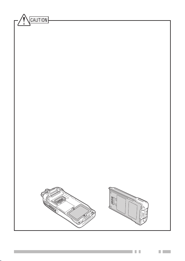
• The orange seal on the reverse side of the transceiver is
important with respect to the waterproof efficiency of the
transceiver. Do not place stickers or other materials on or
around the seal shown in the figure, or on the reverse side of
the battery pack. Doing so will impair the waterproof efficiency
of the transceiver and may cause it to break down. Additionally,
in order to prevent damage to the seal, do not allow it to come
in contact with foreign materials.
iii
Page 6

Information concerning battery packs:
The battery pack includes flammable objects such as organic solvent.
Mishandling may cause the battery to rupture producing flames or
extreme heat, deteriorate, or cause other forms of damage to the
battery. Please observe the following prohibitive matters.
•
Do not disassemble or reconstruct battery!
The battery pack has a safety function and protection circuit to
avoid danger. If they suffer serious damage, the battery may
generate heat or smoke, rupture, or burst into flame.
•
Do not short-circuit the battery!
Do not join the + and – terminals using any form of metal (such
as a paper clip or wire). Do not carry or store the battery pack in
containers holding metal objects (such as wires, chain-necklace or
hairpins). If the battery pack is short-circuited, excessive current will
flow and the battery may generate heat or smoke, rupture, or burst
into flame. It will also cause metal objects to heat up.
•
Do not incinerate or apply heat to the battery!
If the insulator is melted, the gas release vent or safety function is
damaged, or the electrolyte is ignited, the battery may generate
heat or smoke, rupture, or burst into flame.
•
Do not use or leave the battery near fires, stoves, or other
heat generators (areas reaching over 80°C/ 176°F)!
If the polymer separator is melted due to high temperature, an
internal short-circuit may occur in the individual cells and the
battery may generate heat or smoke, rupture, or burst into flame.
•
Do not immerse the battery in water or get it wet by other
means!
If the battery’s protection circuit is damaged, the battery may
charge at extreme current (or voltage) and an abnormal chemical
reaction may occur. The battery may generate heat or smoke,
rupture, or burst into flame.
•
Do not charge the battery near fires or under direct sunlight!
If the battery’s protection circuit is damaged, the battery may
charge at extreme current (or voltage) and an abnormal chemical
reaction may occur. The battery may generate heat or smoke,
rupture, or burst into flame.
iv
Page 7

•
Use only the specified charger and observe charging
requirements!
If the battery is charged in unspecified conditions (under high
temperature over the regulated value, excessive high voltage or
current over regulated value, or with a remodelled charger), it may
overcharge or an abnormal chemical reaction may occur. The
battery may generate heat or smoke, rupture, or burst into flame.
•
Do not pierce the battery with any object, strike it with an
instrument, or step on it!
This may break or deform the battery, causing a short-circuited.
The battery may generate heat or smoke, rupture, or burst into
flame.
•
Do not jar or throw the battery!
An impact may cause the battery to leak, generate heat or smoke,
rupture, and/or burst into flame. If the battery’s protection circuit
is damaged, the battery may charge at an abnormal current (or
voltage), and an abnormal chemical reaction may occur. The
battery may generate heat or smoke, rupture, or burst into flame.
•
Do not use the battery pack if it is damaged in any way!
The battery may generate heat or smoke, rupture, or burst into flame.
•
Do not solder directly onto the battery!
If the insulator is melted or the gas release vent or safety function
is damaged, the battery may generate heat or smoke, rupture, or
burst into flame.
•
Do not reverse the battery polarity (and terminals)!
When charging a reversed battery, an abnormal chemical reaction
may occur. In some cases, an unexpected large amount of current
may flow upon discharging. The battery may generate heat or
smoke, rupture, or burst into flame.
•
Do not reverse-charge or reverse-connect the battery!
The battery pack has positive and negative poles. If the battery
pack does not smoothly connect with a charger or operating
equipment, do not force it; check the polarity of the battery. If the
battery pack is reverse-connected to the charger, it will be reversecharged and an abnormal chemical reaction may occur. The
battery may generate heat or smoke, rupture, or burst into flame.
v
Page 8

•
Do not touch a ruptured and leaking battery!
If the electrolyte liquid from the battery gets into your eyes, wash
your eyes out with fresh water as soon as possible, without
rubbing your eyes. Go to the hospital immediately. If left
untreated, it may cause eye-problems.
•
Do not charge the battery for longer than the specified
time!
If the battery pack has not finished charging even after the
regulated time has passed, stop it. The battery may generate
heat or smoke, rupture, or burst into flame.
•
Do not place the battery pack into a microwave or high
pressure container!
The battery may generate heat or smoke, rupture, or burst into
flame.
•
Keep ruptured and leaking battery packs away from fire!
If the battery pack is leaking (or the battery emits a bad odor),
immediately remove it from flammable areas. Electrolyte
leaking from battery can easily catch on fire and may cause the
battery to generate smoke or burst into flame.
•
Do not use an abnormal battery!
If the battery pack emits a bad odor, appears to have different
coloring, is deformed, or seems abnormal for any other reason,
remove it from the charger or operating equipment and do not
use it. The battery may generate heat or smoke, rupture, or
burst into flame.
vi
Page 9

CONTENTS
UNPACKING AND CHECKING EQUIPMENT .............................. 1
uPPlied accessories ....................................................... 1
s
PREPARATION .............................................................. 2
nsTalling/ removing The (oPTional) BaTTerY Pack ........................ 3
i
nsTalling The anTenna ..................................................... 4
i
nsTalling The BelT cliP .................................................... 4
i
nsTalling The caP over The universal connecTor ......................... 5
i
nsTalling The (oPTional) sPeaker/ microPhone or headseT .............. 5
i
GETTING ACQUAINTED ..................................................... 6
BASIC OPERATIONS ........................................................ 8
wiTching Power on/ oFF ................................................ 8
s
djusTing The volume ...................................................... 8
a
TRUNKING MODE ........................................................... 9
eY oPeraTions ............................................................. 9
k
isPlaY ....................................................................11
d
rogrammaBle FuncTions .................................................13
P
earching For a conTrol channel ........................................14
s
oice calls ................................................................14
v
TaTus calls...............................................................16
s
aTa calls .................................................................16
d
all disPlaYs ..............................................................17
c
iewing The sTack .........................................................18
v
all diverTing .............................................................18
c
ialing mode ..............................................................19
d
eYPad enTrY ..............................................................20
k
mergencY calls ..........................................................20
e
uxiliarY PorT .............................................................20
a
ePorT ...............................................................20
gPs r
ome address .............................................................21
h
iTe lock ..................................................................21
s
vii
Page 10

suB-lcd disPlaY ..........................................................21
wiTching To convenTional mode .........................................21
s
iBraTor ................................................................... 21
v
CONVENTIONAL MODE ....................................................22
eY oPeraTions ............................................................22
k
isPlaY ....................................................................24
d
rogrammaBle FuncTions .................................................25
P
onvenTional oPeraTion ...................................................25
c
canning ...................................................................26
s
mergencY (Trunking) .....................................................26
e
quelch oFF ...............................................................27
s
uieT Talk (qT)/ digiTal quieT Talk (dqT) ..............................27
q
ime-ouT Timer (ToT) .....................................................28
T
usY channel lockouT (Bcl) .............................................28
B
wiTching To Trunking mode ..............................................28
s
ADVANCED OPERATIONS .................................................29
cramBler .................................................................29
s
dTmF (d
gPs P
B
k
c
ual Tone mulTi FrequencY) calls ..............................29
osiTion disPlaY .....................................................29
acklighT ..................................................................30
eY lock ...................................................................30
lock ......................................................................31
BACKGROUND OPERATIONS .............................................32
aTTerY Power indicaTor ..................................................32
B
ignal sTrengTh indicaTor ................................................32
s
VGS-1 OPTIONAL VOICE GUIDE & STORAGE UNIT ...................33
oice recorder ............................................................33
v
oice guide ................................................................35
v
APPENDIX ...................................................................36
viii
Page 11
UNPACKING AND CHECKING EQUIPMENT
The following unpacking instructions are for use by your
Note:
Kenwood
factory.
Carefully unpack the transceiver. We recommend that you
identify the items listed in the following table before discarding
the packing material. If any items are missing or have
been damaged during shipment, file a claim with the carrier
immediately.
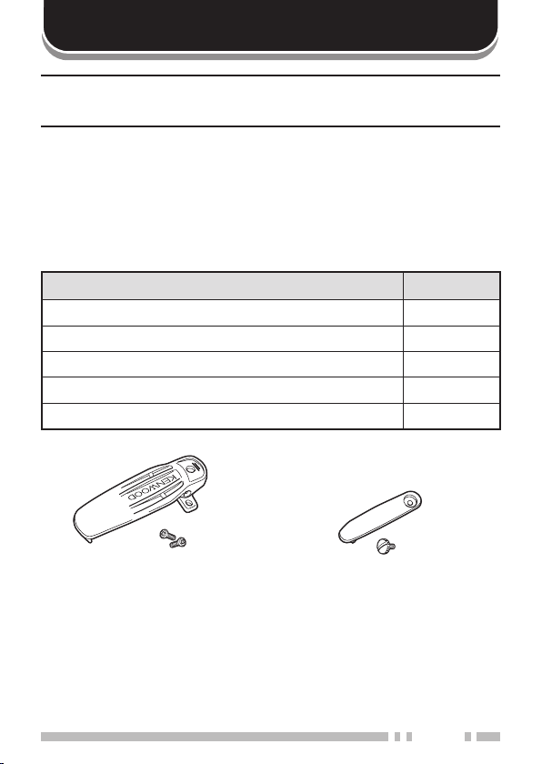
Supplied AcceSSorieS
Belt clip 1
Screw for belt clip 2
Univeral connector cap 1
Screw for connector cap 1
Instruction manual 1
dealer, an authorized
Item Quantity
Kenwood
service facility, or the
Belt clip
+ screws
Universal connector cap
+ screw
1
Page 12

PREPARATION
BAttery pAck precAutionS
Do not use battery packs or battery chargers not recommended
by
Kenwood
Do not recharge the battery pack if it is already fully charged.
◆
Doing so may cause the life of the battery pack to shorten or the
battery pack may be damaged.
After charging the battery pack, disconnect it from the charger.
◆
If the charger power is reset (turned ON after being turned
OFF), recharging will start again and the battery pack will
become overcharged.
Do not use the transceiver while charging the battery pack.
◆
We recommend you switch the transceiver power OFF while
charging is taking place.
Do not charge the battery pack when the battery pack or
◆
transceiver is wet, to avoid the risk of fire or damage. Wipe
the water from thebattery pack or transceiver using a dry cloth
before charging.
Do not short the battery terminals or dispose of the battery by
◆
fire.
Never attempt to remove the casing from the battery pack.
◆
■
Charging a Battery Pack
For charging procedures, refer to the battery charger
Instruction Manual.
.
2
Page 13
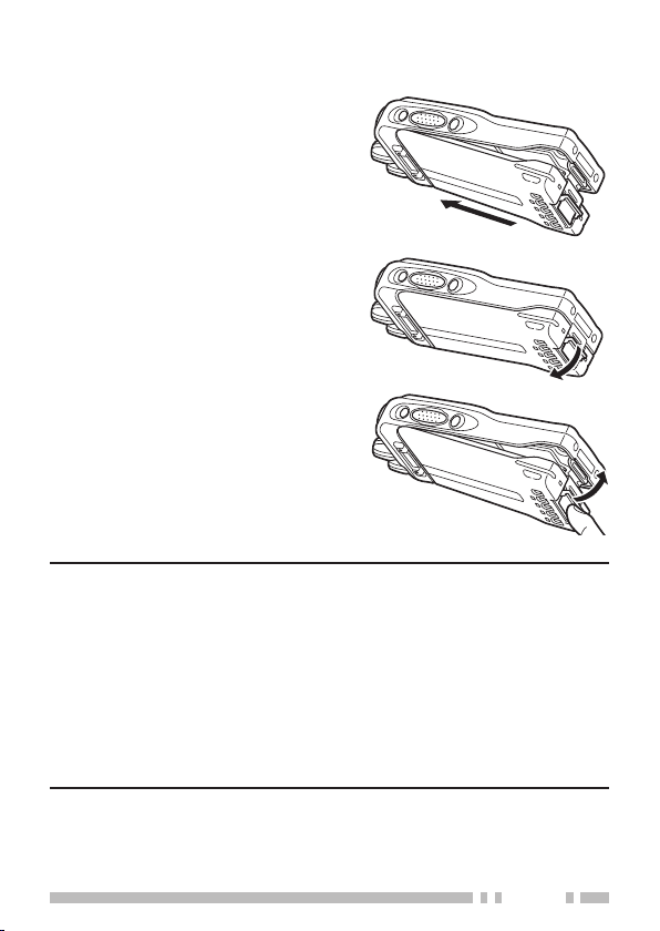
inStAlling/ removing the (optionAl) BAttery pAck
Match the guides of the battery
1
pack with the corresponding
grooves on the upper rear of
the transceiver, then firmly
press the battery pack to lock it
in place.
Lock the safety catch to
2
prevent accidentally pressing
the release latch and removing
the battery pack.
To remove the battery pack,
3
lift the safety catch, press the
release latch, then pull the
battery pack away from the
transceiver.
Note:
To lift the battery pack safety catch, use a piece of hardened
◆
plastic or metal, such as a screwdriver, that is no more than
6 mm wide and 1 mm thick. It is imperative that you place the
implement under only the lip of the safety catch so that you do
not damage the release latch.
Before charging a battery pack that is attached to the
◆
transceiver, ensure that the safety catch is firmly closed.
While operating the transceiver using a Li-ion or
◆
Ni-MH battery pack in areas with an ambient temperature of
–10°C/ +14°F and lower, operating time may be shortened.
3
Page 14
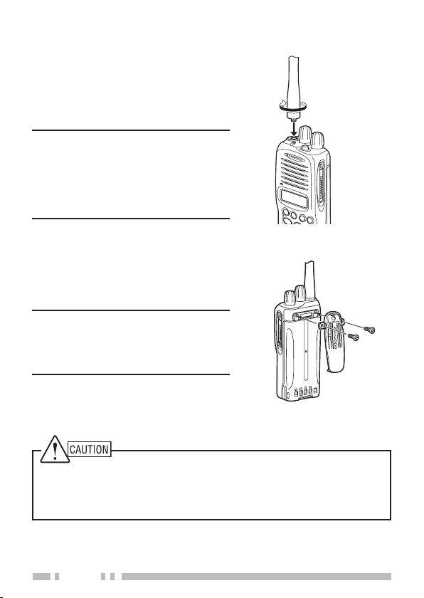
inStAlling the (optionAl) AntennA
S
A
B
C
1
MI
C
<
>
Screw the antenna into the
connector on the top of the
transceiver by holding the antenna
at its base and turning it clockwise
until secure.
The antenna is neither a
Note:
handle, a key ring retainer, nor a
speaker/ microphone attachment
point. Using the antenna in these
ways may damage the antenna
and degrade your transceiver’s
performance.
inStAlling the Belt clip
If necessary, attach the belt clip
using the two supplied
3 x 8 mm screws.
If the belt clip is not installed,
Note:
its mounting location may get hot
during continuous transmission
or when left sitting in a hot
environment.
Do not use glue which is designed to prevent screw loosening when
installing the belt clip, as it may cause damage to the transceiver.
Acrylic ester, which is contained in these glues, may crack the
transceiver’s back panel.
4
Page 15
inStAlling the cAp over the univerSAl connector
S
A
B
C
1
2
A
B
C
5
JK
L
8
0
T
U
V
4
G
H
I
7
P
Q
R
S
3
D
E
F
6
M
N
O
MI
C
9
#
W
X
Y
Z
<
>
S
A
B
C
1
MI
C
<
>
If you are not using an optional
speaker/ microphone or headset,
install the cap over the universal
connector using the supplied
4 x 6 mm screw. Ensure that the
cap fits tightly over the connector.
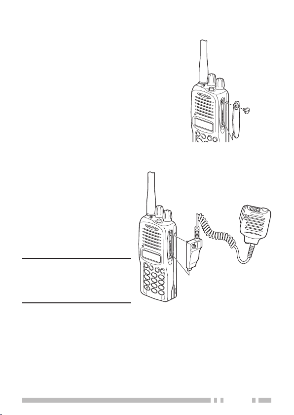
inStAlling the (optionAl) SpeAker/ microphone or heAdSet
Insert the guide of the
1
speaker/ microphone
connector into the
groove of the universal
connector.
Secure the connector in
2
place using the attached
screw.
When not using
Note:
an optional speaker/
microphone or headset,
install the cap over the
universal connector.
5
Page 16

GETTING ACQUAINTED
S
ABC
1
2
ABC
5
JK
L
8
0
TUV
4
GH
I
7
P
QR
S
3
DE
F
6
MN
O
MI
C
9
#
W
XYZ
<
>
SpeakerMicrophone
Antenna connector
q
Connect an antenna here {page 4}.
Selector
w
Rotate to select your desired channel/ call address (voice
calls) or status (status calls).
6
Page 17

Power switch/ Volume control
e
Turn clockwise to switch ON the transceiver. Rotate to
adjust the volume. Turn counterclockwise fully to switch
OFF the transceiver.
Transmit/ Busy indicator
r
This LED lights red while transmitting and green while
receiving a call.
Auxiliary (orange) key
t
Press to activate its programmable function*.
Safety Catch
y
Lock this catch to avoid accidentally pressing the release
latch and removing the battery pack {page 3}.
Release Latch
u
Press the release latch to unlock and remove the battery
pack {page 3}.
Side 1 key
i
Press to activate its programmable function*.
PTT (Push-To-Talk) switch
o
Press this switch, then speak into the microphone to place
a call.
Side 2 key
!0
Press to activate its programmable function*.
S, A, <B, and C> keys
!1
Press to activate their programmable functions*.
DTMF keypad
!2
Press the keys on the keypad to make DTMF calls and to
enter ID numbers and messages.
Universal connector
!3
Connect a speaker/ microphone or headset here {page 5}.
Otherwise, keep the supplied cap in place.
* Programmable functions vary, depending on the transceiver
operating mode. Refer to Trunking Mode {page 9} or Conventional
Mode {page 22} for applicable functions.
7
Page 18

BASIC OPERATIONS
Switching power on/ oFF
Turn the
transceiver ON.
• A beep sounds and the display momentarily lights up.
• If the Transceiver Password function is programmed, “PASSWORD”
appears on the display. If a key has been programmed as
Transceiver Password
“PASSWORD” appears on the display. You must enter the
password to unlock the transceiver. Refer to “Transceiver
Password”, below.
Turn the
switch the transceiver OFF.
■
Transceiver Password
To enter the transceiver password:
Press the DTMF keys corresponding to the password
1
digits.
• Alternatively, you can enter the password by rotating the
• Press the
Press the S or key to confirm the password.
2
• If you enter an incorrect password, an error tone sounds
switch/
Power
switch/
Power
selector
to accept the entered digit and move to the next digit.
Press and hold the A or # key to delete all entered
characters.
and the transceiver remains locked.
Volume
Volume
to select a digit, followed by pressing the C> key
or # key to delete an incorrect character.
A
control clockwise to switch the
, you must press this key first, before
control counterclockwise to
AdjuSting the volume
Rotate the
Clockwise increases the volume and counter-clockwise
decreases it.
8
Power
switch/
Volume
control to adjust the volume.
Page 19

S
ABC
1
2
AB
C
5
JK
L
8
0
TUV
4
GHI
7
PQRS
3
DE
F
6
MN
O
MI
C
9
#
W
XY
Z
<
>
key operAtionS
TRUNKING MODE
9
Page 20

Selector
q
Rotate to select your desired call address or status.
Power switch/ Volume control
w
Turn clockwise to switch ON the transceiver. Rotate to
adjust the volume. Turn counterclockwise fully to switch
OFF the transceiver.
Auxiliary (orange) key
e
Press to activate its programmable function {page 13}.
The default setting is None.
Side 1 key
r
Press to activate its programmable function {page 13}.
The default setting is Call.
PTT (Push-To-Talk) switch
t
Press this switch, then speak into the microphone to call a
station.
Side 2 key
y
Press to activate its programmable function {page 13}.
The default setting is Clear.
S key
u
Press to activate its programmable function {page 13}.
The default setting is Status/Stack.
A key
i
Press to activate its programmable function {page 13}.
The default setting is Redial.
<B key
o
Press to activate its programmable function {page 13}.
The default setting is Lamp.
C> key
!0
Press to activate its programmable function {page 13}.
The default setting is Clock.
DTMF keypad
!1
Press these keys to enter ID numbers and messages.
10
Page 21

diSplAy
Indicator Description
Displays call addresses, received
messages, and transceiver status
messages.
Displays received call types, transceiver
functions, status numbers, and output power.
Displays the strength of received signals. An
antenna and all 3 strength bars represents
strong signals while the antenna by itself (no
strength bars) represents weak signals.
Flashes when you receive a message.
Lights when a message is stored in the
queue memory.
Appears when call diversions on your
transceiver have been set up.
Appears when the Scrambler function is
activated.
Displays the battery power status as high,
sufficient, low, or very low.
Appears when the Auto Recording function
on the VGS-1 option is activated.
Appears when an Auto Reply Message on
the VGS-1 option is activated.
Appears when the Vibrator function is
activated.
Appears when the AUX function has been
activated.
11
Page 22

MPT Status Messages
Display Transceiver status
<<NO REPLY>> No Reply
<<NU>> Call Address Invalid
<<INVALID>> Calling Invalid
<<HOLDING>> Waiting for response from calling address
<<ENGAGED>> Calling address is engaged
<<PARTY BUSY>> Party Busy
<<QUEUED>> System Queued
<<I-PREFIX>> Call received from Inter-Prefix
<<I-FLEET> Call received from Inter-Fleet
<<PABX>> Received PABX Call
<<PSTN>> Received PSTN Call
12
Page 23

progrAmmABle FunctionS
The
Auxiliary, Side 1, Side 2, S, A, <B
can be programmed with the functions listed below. Please
contact your dealer for further details on these functions.
• Auto Reply Message
• AUX
• Call
• Call Address Down
• Call Address Up
• Clear
• Clock
• Conventional
• Dialing
• Dialing Mode
• Emergency
4
• GPS Position Display
• Home Address
1
“Auto Reply Message” and “Playback” can be programmed only when
the optional VGS-1 board has been installed.
2
“Call Address Down” and “Call Address Up” can be programmed only
on the optional microphone PF1, and PF2 keys.
3
“Dialing Mode” can be selected when Keypad Operation is set to
Programmable.
4
“Emergency” can be programmed only on the Auxiliary (orange) key.
5
“GPS Position Display” can be assigned only if one of the COM ports
is configured for GPS.
6
“Status/ Stack” can be programmed only on the S key.
7
“Vibrator” can be set up only when it is configured for Universal
Connector Pin No. 11.
1
2
2
3
5
, and C> keys
• Key Lock
• Lamp
• Network Select
• None
• Playback
• Redial
• Scrambler
• Send the GPS Data
• Site Lock
• Status/Stack
• Sub LCD Display
• Transceiver Password
• Vibrator
1
6
7
13
Page 24

SeArching For A control chAnnel
After switching the power ON, press any key while the
power-on text or unit number is displayed to begin searching
for a control channel.
• If no action is performed for 2 seconds, the transceiver will
automatically begin searching for a control channel.
• “---” appears on the sub-display and an arrow scrolls across the main
display while the transceiver is searching for a control channel.
• If more than one network is available, press the key programmed
as
Network Select
to manually change networks.
voice cAllS
Making a Voice Call
■
Rotate the selector or press the keys programmed as
1
Call Address Up
your desired call address.
Press the
2
Call
switch to initiate the call.
• “CALLING” appears on the main display and “SVC”
appears on the sub-display.
When the call is connected, a timer appears on the
3
display.
• The timer can be set to either count up (increasing number)
or down (decreasing number).
Press the
4
• The LED lights red while transmitting.
• The sub-display shows your transmit power. A single
Press the
5
PTT
triangle (▲) represents low power and dual triangles (▲▲)
represents high power.
Clear
If the call time expires before you press the
the call will be automatically terminated.
• “END” momentarily appears on the display before returning
to the call address of the call you just made.
14
and
Call Address Down
key (default:
Side 1
key) or the
to select
PTT
switch to transmit; release it to receive.
key (default:
key) to end the call.
Side 2
Clear
key,
Page 25

Receiving a Voice Call
■
When a call is received, the caller’s unit number
1
appears on the main display.
• If you have the caller’s address set up in your transceiver,
the call address is displayed instead of the unit number.
• Depending on the type of call being received, a code will
appear on the sub-display:
CAL:
An individual call is being received.
GRP:
A group conference call is being received.
BCC:
A group broadcast call is being received.
• Special calls are denoted as follows:
I-FLEET:
I-PREFIX:
PABX:
PSTN:
Press the
2
• The remaining call time appears on the display.
When the call ends, the display returns to the call
3
A call from a different fleet (Inter-Fleet).
A call from a different prefix (Inter-Prefix).
A call from a PABX telephone system.
A call from a PSTN telephone system.
switch to respond to the call.
PTT
address that was previously displayed. However, if
you end the call by pressing the
Clear
key, “END”
momentarily appears on the display before returning to
the call address.
15
Page 26

StAtuS cAllS
Making a Status Call
■
Rotate the selector or press the keys programmed as
1
Call Address Up
your desired call address.
Press the
2
the selector to select your desired status.
• The status number appears on the sub-display.
Press the
3
has been programmed) to send the status.
• “CALLING” appears on the display.
When the status has been received by the called party,
4
“COMPLETE” momentarily appears on the display
before returning to the previously selected call address.
Receiving a Status/Short Data Message Call
■
When a call is received, the icon appears on the
1
display and flashes.
• The icon remains on the display when there is data in the
To view the status or message, refer to “
2
on page 18.
Status/ Stack
Call
stack.
and
key (or
Call Address Down
key (default: S key), then rotate
switch if “PTT to Initiate Call”
PTT
to select
iewing the Stack
V
dAtA cAllS
Making a Data Call
■
Enter control code 2 to make a SDM (Short Data
1
Message) call.
Press the key, then enter your message.
2
• Enter characters using the keypad or by rotating the
selector. When rotating the selector, press the <B or C>
key to set the selected character.
• To clear a character, press the
entered characters, press and hold the
key. To clear all
Clear
Clear
”,
key.
16
Page 27

Press the key to end your message.
3
Enter the ID number of the unit you want to send the
4
message to.
Press the
5
transmit.
Receiving a Data Call
■
When a call is received, the
1
display and flashes.
• The icon remains on the display when there is data in
the stack.
To view the message, refer to “
2
page18.
switch, the
PTT
key, or the # key to
Call
icon appears on the
iewing the Stack
V
”, on
cAll diSplAyS
The following messages may appear on the display under
certain circumstances:
•
ENGAGED:
•
HOLDING:
the base station.
•
INVALID:
•
NU:
The called party could not be reached (Number
Unobtainable).
•
NO REPLY:
not respond to the call.
•
PARTY BUSY:
from making calls.
•
QUEUED:
your call will be connected when a channel becomes free.
The called party is in another call.
The transceiver is confirming the call made by
You entered an invalid call address.
The called party has been called, but they did
The called party is temporarily prohibited
All communication channels are currently in use;
17
Page 28

viewing the StAck
Press the
1
• If there is no data in the stack, “————————————”
Rotate the selector to view the stack entries.
2
• “NEW” momentarily appears on the sub-display if the message
• In the sub-display, “S” represents a status stack entry, “V”
Press the <B and C> keys to scroll through the selected
3
Status/ Stack
appears on the main display and “–00” appears on the
sub-display.
has not yet been viewed.
represents a voice stack entry, and “D” represents a data stack
entry.
entry, to view the entire entry. Press the A key to toggle
between the time/date of the received call and the caller ID.
To erase an entry, select the desired entry and press the
4
To erase all entries, select press and hold the
5
key.
Clear
• “DELETE?” appears on the display. Press the S or key to
confirm the deletion. Press the A or # key to cancel.
• “DELETE?” appears on the main display and “ALL” appears on
the sub-display. Press the S or key to confirm the deletion.
Press the A or # key to cancel.
key twice to enter the stack.
Clear
key.
cAll diverting
Diverting Your Own Calls
■
Enter control code
1
transceiver.
Press the key, then enter the ID number of the unit to
2
where you want your calls diverted.
Press the
3
switch, the
PTT
up the call diversion.
• “CALLING” appears on the display.
to divert your calls to a different
41
key, or the # key to set
Call
18
Page 29

• When the call divert is set, “COMPLETE” momentarily
appears on the display. Additionally, the icon appears
on the display and flashes.
To end the call diversion, enter control code
4
press the
• “CALLING” appears on the display.
• When the call divert is cleared, “COMPLETE” momentarily
appears on the display.
Diverting Third Party Calls
■
Enter control code
1
Press the
2
switch, the
PTT
44
key, or the # key.
Call
to divert third party calls.
key, then enter the ID number of the unit
#41
from which you want calls diverted.
Press the key, then enter the ID number of the unit to
3
where you want the calls diverted.
Press the
4
switch, the
PTT
key, or the # key to set
Call
up the call diversion.
• “CALLING” appears on the display.
• When the call divert is set, “COMPLETE” momentarily
appears on the display.
To end the call diversion, enter control code
5
#44
followed by the key and the ID number of the unit
from which calls are being diverted, then press the
switch, the
• “CALLING” appears on the display.
• When the call divert is cleared, “COMPLETE” momentarily
appears on the display.
key, or the # key.
Call
, then
PTT
diAling mode
Press the key programmed as
number using the keypad.
You can select
Note:
to Programmable.
Dialing Mode
Dialing Mode
when Keypad Operation is set
to enter a dialing
19
Page 30

keypAd entry
Besides using the selector, you can enter dialing codes
manually, by entering the numbers using the keypad.
• Refer to the dialing codes listed in the appendix, starting on page 36.
Redialing
■
If a key has been programmed with
redial previously dialed call addresses.
Press the key programmed as
1
Rotate the selector to select 1 of the 3 last dialed
2
numbers.
Press the
3
key or the
Call
Redial
switch to initiate the call.
PTT
Redial,
.
you can easily
emergency cAllS
If your transceiver has been programmed with the Emergency
function, you can make emergency calls.
Only the Auxiliary (orange) key can be programmed with the
Note:
Emergency function.
Press and hold the key programmed as
• Depending on the delay time programmed into your transceiver,
the length of time you must hold the
Emergency
Emergency
.
key will vary.
AuxiliAry port
If a key has been programmed with the
press that key to turn the Auxiliary Port on and off.
• When the Auxiliary Port is activated, the AUX indicator
( ) appears on the display.
function, you can
AUX
gpS report
If a GPS unit (NMEA-0183 format) is installed on your
transceiver and the
programmed onto a key by your dealer, press the this key to
send your location data.
20
Send the GPS Data
function has been
Page 31

home AddreSS
If a key has been programmed with the Home Address
function, you can press that key to jump to the
pre-programmed call address.
• “HAD” appears in the sub-display when the selected call address is
the Home Address.
Press
Home Address
call address you were using.
a second time to return to the previous
Site lock
Press and hold this key for 1 second to lock the Site. “SITE
LOCKED” momentarily appears on the display. Press and hold
this key again for 1 second to cancel Site Lock.
SuB-lcd diSplAy
If a key has been programmed with the
function, you can press that key to jump to the toggle the
sub-display between “SVC”, the current control channel
number, and the signal strength readout.
Sub-LCD Display
Switching to conventionAl mode
Depending on how your transceiver is programmed, you can
enter Conventional Mode in one of two ways:
Manual:
as
only works when no signals are currently being received.
Auto:
Mode when you are outside the network area.
When in Trunking Mode, press the key programmed
Conventional
The transceiver automatically changes to Conventional
to change the operating mode. This function
viBrAtor
Press and hold this key for 1 second to toggle the vibrator function
ON and OFF. When the vibrator is on, the transceiver will vibrate
when a voice call (Individual/GroupPSTN/PABX) is received and
when a status message, SDM, or NPD is in the stack.
• When the Vibrator function is activated, the Vibrator indicator
( ) appears on the display.
21
Page 32

S
ABC
1
2
AB
C
5
JK
L
8
0
TUV
4
GHI
7
PQRS
3
DE
F
6
MN
O
MI
C
9
#
W
XY
Z
<
>
key operAtionS
CONVENTIONAL MODE
22
Page 33

Selector
q
Rotate to select your desired channel.
Power switch/ Volume control
w
Turn clockwise to switch ON the transceiver. Rotate to
adjust the volume. Turn counterclockwise fully to switch
OFF the transceiver.
Auxiliary (orange) key
e
Press to activate its programmable function {page 25}.
The default setting is None.
Side 1 key
r
Press to activate its programmable function {page 25}.
The default setting is Squelch Off.
PTT (Push-To-Talk) switch
t
Press this switch, then speak into the microphone to call a
channel.
Side 2 key
y
Press to activate its programmable function {page 25}.
The default setting is Clear.
S key
u
Press to activate its programmable function {page 25}.
The default setting is Scan.
A key
i
Press to activate its programmable function {page 25}.
The default setting is Scan Delete/Add.
<B key
o
Press to activate its programmable function {page 25}.
The default setting is Lamp.
C> key
!0
Press to activate its programmable function {page 25}.
The default setting is Clock.
DTMF keypad
!1
Press these keys to make DTMF calls {page 29}.
23
Page 34

diSplAy
Indicator Description
Displays channel numbers (or names) and
received messages.
Displays channel numbers and transceiver
functions.
Displays the strength of received signals.
An antenna and all 3 strength bars
represents strong signals while the antenna
by itself (no strength bars) represents weak
signals.
Appears when the Squelch Off function has
been activated (squelch has been turned
off).
Appears while scanning.
Flashes when you receive a message.
Lights when a message is stored in the
queue memory.
Appears when the Scrambler function is
activated.
Displays the battery power status as high,
sufficient, low, or very low.
Appears when the Auto Recording function
on the VGS-1 option is activated.
Appears when the selected channel is
added to the scanning sequence.
24
Page 35

progrAmmABle FunctionS
The
Auxiliary, Side 1, Side 2, S, A, <B
can be programmed with the functions listed below. Please
contact your dealer for further details on these functions.
, and C> keys
• Channel Down
• Channel Up
• Clear
• Clock
• Emergency (Trunking)
• GPS Position Display
• Key Lock
1
“Emergency (Trunking)” can be programmed only on the Auxiliary
(orange) key.
2
“GPS Position Display” can be assigned only if one of the COM ports
is configured for GPS.
3
“Playback” can be programmed only when the optional VGS-1 board
has been installed.
1
2
• Lamp
• None
• Playback
• Scan
• Scan Delete/Add
• Scrambler
• Squelch Off
3
conventionAl operAtion
Rotate the selector or press the keys programmed as
1
Channel Up
channel.
Press the
2
Squelch function OFF, in order to monitor any activity on
the channel.
• The icon appears on the display.
• The LED lights green and you will hear background noise.
Press the
3
Release the
• For best sound quality at the receiving station, hold the
microphone approximately 3 ~ 4 cm from your mouth.
and
Channel Down
Squelch Off
switch and speak into the microphone.
PTT
PTT
key (default:
switch to receive.
to select your desired
key) to turn the
Side 1
25
Page 36

ScAnning
Press the
• While scanning, the icon and “SCAN” appear on the display.
• When a call is received, scanning stops and the channel number (or
channel name if a name has been set up) appears. Press the
switch and speak into the microphone to respond to the call. The
transceiver will continue scanning after an adjustable time delay if
the
PTT
To stop scanning, press the
Add to Scan/ Delete from Scan
■
Press the
remove each channel to or from the scan sequence.
• The channel add indicator ( ) will appear on
the display when the selected channel is added to the scan
sequence.
Scan Revert
■
During scan, when pressing the
transmit on the revert channel. Four types of Scan Reverts
which can be programmed by your dealer are available.
•
Last Called:
•
Last Used:
•
Selected:
•
Selected + Talkback:
activating Scan is the revert channel. However, you can
respond (talkback) to a call if you are currently receiving on a
different channel.
key (default: S key) to begin scanning.
Scan
switch is released and no further signal is received.
Scan Delete/Add
The last channel on which you received a call.
The last channel to which you responded.
The channel you selected prior to activating Scan.
The channel you selected prior to
key again.
Scan
key (default: A key) to add or
switch, you can
PTT
PTT
emergency (trunking)
The Emergency (Trunking) function will place an Emergency
Call (page 20) when entering Trunking mode.
• This function can be configured only when Trunking Search Delay
Time is not set to "Off" and Automatic Mode Change is set to "Alert".
• Emergency (Trunking) cannot be used if the Trunking Search has
not found a Control Channel.
26
Page 37

Only the Auxiliary (orange) key can be programmed with the
Note:
Emergency function.
Press and hold the key programmed as
(Trunking)
.
Emergency
Squelch oFF
Press the
Squelch Off
cannot hear during normal operation and to adjust the volume
when no signals are present on your selected channel.
• The icon appears and the Busy LED lights green while Squelch
Off is activated.
Press
Squelch Off
key to listen to weak signals that you
again to return to normal operation.
quiet tAlk (qt)/ digitAl quiet tAlk (dqt)
Your dealer may have programmed QT or DQT signaling on
your transceiver channels. A QT tone/ DQT code is a subaudible tone/code which allows you to ignore (not hear) calls
from other parties who are using the same channel.
When a channel is set up with a QT tone or DQT code, squelch
will open only when a call containing a matching tone or code is
received. Likewise, signals you transmit will be heard only by
parties whose QT/ DQT signaling matches your transceiver.
If a call containing a different tone or code is made on the
same channel you are using, squelch will not open and you
will not hear the call. Although it may seem like you have your
own private channel while using QT/ DQT, other parties can
still hear your calls if they set up their transceiver with the same
tone or code.
27
Page 38

time-out timer (tot)
The purpose of the Time-out Timer is to prevent any caller from
using a channel for an extended period of time.
If you continuously transmit for a period of time that exceeds
the programmed time set by your dealer (default is 1 minute),
the transceiver will stop transmitting and an alert tone will
sound. To stop the tone, release the
Your dealer can program the TOT time in the range of 15
seconds to 20 minutes.
PTT
switch.
BuSy chAnnel lockout (Bcl)
When activated, BCL prevents you from interfering with other
parties who may be using the same channel that you selected.
Pressing the
your transceiver to emit an alert tone and transmission will be
inhibited (you cannot transmit). Release the
the tone and return to receive mode.
switch while the channel is in use will cause
PTT
switch to stop
PTT
Switching to trunking mode
Depending on how your transceiver is programmed, you can
return to Trunking Mode in one of three ways:
Manual:
Auto:
searches for the network. When it finds the network, the
transceiver automatically changes to Trunking Mode. An alert
tone sounds to notify you when the operating mode changes.
Alert:
searches for the network. When it finds the network, an alert
tone sounds. Press the
mode.
Press the
While in Conventional Mode, the transceiver periodically
While in Conventional Mode, the transceiver periodically
key to change the operating mode.
Clear
key to change the operating
Clear
28
Page 39

ADVANCED OPERATIONS
ScrAmBler
Although the scrambler function does not offer complete privacy
with your calls, it does prevent others from easily listening in on
your calls. When activated, the transceiver distorts your voice
so that anybody listening to your call will be unable to clearly
hear what you are saying.
In order for members of your own group to clearly hear your
call while you are using the scrambler, all other members must
also activate the scrambler functions on their transceivers. This
distorts everybody’s voice while transmitting and corrects the
voice message on your own transceiver when you receive the
call.
To activate the scrambler, press the key programmed as
Scrambler
• The icon appears on the display while the scrambler is active.
To deactivate the scrambler, press the
Note:
can activate or deactivate the built-in scrambler function of the
transceiver, or they can add a more secure optional scrambler
board to your transceiver. Ask your dealer for details.
dtmF (duAl tone multi Frequency) cAllS
Press and hold the
using the front panel keypad.
• If you release the
.
Scrambler
There are 2 options for using the scrambler. Your dealer
switch, then enter the desired digits
PTT
switch, transmit mode will end even if the
complete number has not been sent.
PTT
key again.
gpS poSition diSplAy
If a GPS unit (NMEA-0183 format) is installed on your
transceiver and the GPS Position Display function has been
programmed onto a key by your dealer, press the
Position Display
altitudinal values on the main display of the transceiver.
key to display latitudinal, longitudinal and
GPS
29
Page 40

BAcklight
To turn the transceiver display backlight on, press the key
.
Lamp
• Once activated, the backlight remains on for 5 seconds.
• Pressing any key other than the
Volume
reset the backlight timer, allowing it to remain lit for an additional 5
seconds.
control, and the
Lamp
switch, the
PTT
key while the backlight is on will
Power
switch/
To turn the transceiver backlight off immediately, press the
key while the backlight is on.
Lamp
key lock
This function is used to help prevent any accidental operation
of the transceiver.
To lock the transceiver keys, press and hold the key
programmed as
• "LOCKED" momentarily appears on the display.
• In Conventional Mode, you can continue to use the
Lamp
• In Trunking Mode, you can continue to use the
Emergency, Key Lock
, and
Key Lock
Squelch Off
To unlock the keys, press and hold the
for approximately 1 second.
keys.
, and
Lamp
keys.
Call, Clear
Key Lock
Key Lock
,
key again.
,
30
Page 41

clock
If activated by your dealer, your transceiver can track the time
and date with its built-in clock. To view the clock any time,
press the key programmed as
If programmed by your dealer, the time will display momentarily
when the transceiver power is turned ON.
Removing the battery pack or leaving the battery pack
Note:
uncharged for extended periods will cause the clock time to clear.
■
Clock Setup
To set the year, month, day, and time:
With the transceiver power OFF, press and hold the
1
key while turning the transceiver power ON.
C>
• The current year setting appears.
Rotate the selector to select the year, then press the
2
key to cycle to the month setting.
S
• Repeat this step, to cycle through the day, hour, and
minute settings.
Press the S key again, to return to the year setting.
3
• A triple beep will sound, indicating that your selections
have been set into the transceiver memory.
Turn the transceiver power OFF and then back ON to
4
return to normal operation.
Clock
.
31
Page 42

BACKGROUND OPERATIONS
High Sufficient Low Very Low
Strong Medium Weak Very Weak
BAttery power indicAtor
The battery power indicator displays the battery power
remaining, as illustrated below:
When the battery power is “Very Low”, replace or recharge the
battery pack.
If activated by your dealer, an alert tone will sound every 30
seconds and the LED indicator will blink red when the battery
power is “Low”.
SignAl Strength indicAtor
The signal strength indicator displays the strength of received
calls:
32
Page 43

VGS-1
When using the optional VGS-1 voice guide & storage unit, you
gain access to the voice recorder and voice announcement
functions. Ask your dealer for details.
OPTIONAL VOICE GUIDE & STORAGE UNIT
voice recorder
The voice recorder function allows you to record your
conversations and create voice memos and automated
message responses.
■
Auto Recording
If activated, the auto recording function will continuously
record all transmitted and received signals. The recording
storage area retains 30 seconds of recording, so all
transmitted and received signals are simultaneously
recorded and erased, leaving only the last 30 seconds of
recording in memory.
• The auto recording indicator ( ) appears when
this function is activated.
■
Voice Memos
To record a voice memo, for later playback:
Press and hold the key programmed as
1
approximately 1 second.
• The duration of recording memory will appear on the
display and begin counting down.
Speak into the transceiver to record your voice memo.
2
Press the
3
any time and store it into the transceiver memory.
• If the memory becomes full, recording will stop
• “WRITING” appears on the display while the recording is
Side 2, S
automatically and store the voice memo to memory.
being stored to memory.
, or key to end the recording at
Playback
for
33
Page 44

■
Auto Reply Message (Trunking Mode Only)
You can set the transceiver to automatically respond to
Individual Calls:
Press the key programmed as
1
Auto Reply Message
enter Auto Reply Message mode.
• The Auto Reply Message indicator ( )
appears on the display.
When you receive an Individual Call, Auto Reply will
2
begin after waiting for 3 seconds, the transceiver
will send an automatic response to the caller, and
“GREETING” appears on the display.
• If you are available to receive the call, press any key to
disable the auto response.
• If memory is available on your transceiver for recording,
“I am not available. Leave your Message.” will be sent to
the caller. The caller can then leave a recorded message
on your transceiver which you can later recall and listen
to. When a message is stored on your transceiver, “MSG
RCVD” appears on the display.
• If no memory is available on your transceiver for recording,
“I am not available.” will be sent to the caller and “MEMORY
FULL” appears on the display.
to
34
Page 45

■
Playback
To play back a recorded conversation, memo, or message:
Press the key programmed as
1
Playback
to enter
Playback mode.
• If the last action on your transceiver was to auto record
your conversation, “STORE?” will appear on the display,
otherwise a recording channel with the time of the
recording will appear.
• To store the conversation record in the next available
recording channel, press the
conversation, press the A or # key. To skip to the stored
recording channels, press the S or key. To skip back
5 seconds, press the
press the C> key.
Rotate the selector to select the channel which you want
2
key. To skip ahead 5 seconds,
<B
key. To clear the
Side 2
to play back.
• “RM” represents automated reply messages.
• “AR” represents auto-recorded conversations.
• “VM” represents voice memos.
The transceiver will announce the channel, then the
3
recording will automatically play back.
• When the entire recording has been played,
“END OF MSG” is displayed.
• To delete the selected recording, press the
clear all the recorded data, press and hold the A or # key.
A confirmation message will appear on the display; press
the S or key to delete the recording(s) or the A or # key
to cancel.
or # key. To
A
voice guide
When pressing a transceiver key, an audio voice will announce
the key function. If programmed by your dealer, an audio voice
will also announce the selected call address, when changing
call addresses.
35
Page 46

APPENDIX
2 Digit Dialing
Function Dial String
Individual number 20 ~ 89
Group number 90 ~ 99
3 Digit Dialing
Function Dial String
Individual number 200 ~ 899
Group number 900 ~ 998
Emergency operator 112, 999
Enter the open channels 101 ~ 110
Network operator services
4 Digit Dialing
Function Dial String
PABX call 1000 ~ 8999
5 Digit Dialing
100, 111, 121, 131, 141, 151, 161,
171, 181, 191
Function Dial String
PABX call (single address
word calls)
PABX call (extended
addressing protocol)
36
First string (3 ~ 6) + Second string
(1000 ~ 8999)
First string (0, 7, or 8) + Second string
(0000 ~ 9999)
Page 47

6 Digit Dialing
Function Dial String
Common prefix Inter-fleet
individual call
Common prefix Inter-fleet
group call
PABX call (extended
addressing protocol)
7 Digit Dialing
Function Dial String
Common prefix Inter-fleet
individual call
Common prefix Inter-fleet
group call
PABX call (extended
addressing protocol)
8 Digit Dialing
Function Dial String
PSTN call
PABX call (extended
addressing protocol)
Fleet # (2001 ~ 6050) + Individual #
(20 ~ 89)
Fleet # (2001 ~ 6050) + Group # (90
~ 99)
First string (0, 7, or 8) + Second string
(00000 ~ 99999)
Fleet # (2001 ~ 6050) + Individual #
(200 ~ 899)
Fleet # (2001 ~ 6050) + Group # (900
~ 998)
First string (0, 7, or 8) + Second string
(000000 ~ 999999)
First string (0) + Second string
(0000000 ~ 9999999)
First string (7 or 8) + Second string
(0000000 ~ 9999999)
37
Page 48

9 Digit Dialing
Function Dial String
Inter-prefix Inter-fleet
individual call
Inter-prefix Inter-fleet group
call
PSTN call
PABX call
10 Digit Dialing
Function Dial String
Inter-prefix Inter-fleet
individual call
Inter-prefix Inter-fleet group
call
PSTN call
11 ~ 31 Digit Dialing (Common)
Function Dial String
PSTN call
Prefix # (200 ~ 327) + Fleet # (2001 ~
6050) + Individual # (20 ~ 89)
Prefix # (200 ~ 327) + Fleet # (2001 ~
6050) + Group # (90 ~ 99)
First string (0) + Second string
(00000000 ~ 99999999)
First string (7 or 8) + Second string
(00000000 ~ 99999999)
Prefix # (200 ~ 327) + Fleet # (2001 ~
6050) + Individual # (200 ~ 899)
Prefix # (200 ~ 327) + Fleet # (2001 ~
6050) + Group # (900 ~ 998)
First string (0) + Second string
(000000000 ~ 999999999)
First string (0) + Second string
(0000000000 ~ 999999999999999999
999999999999)
A maximum of 31 digits consisting of a 1-digit first string and
Note:
a 10- to 30-digit second string can be used for a dial string.
38
Page 49

Control Codes
Function Dial String
Call setup abandoned, call complete
Send status for dispatcher (status 0)
Send status for dispatcher (status nn)
Group call (Conference call)
Group call (Broadcast call)
Priority voice system-wide-call
Emergency voice system-wide-call
Priority np data system-wide-call
Emergency np data system-wide-call
Short data system-wide-call
Standard voice system-wide-call
Short data on the control channel
Divert own calls (voice & data, voice only,
data only)
Divert third party calls (voice & data, voice
only, data only)
Queue incoming calls
Don’t disturb (voice & data, voice only, data
only)
Priority call
Emergency call
Abbreviated Dialing
#
0
0nn
1
11
1981#
1982#
1983#
1984#
1985#
1987#
2
41, 411, 412
44, 441, 442
48#
49#, 491#, 492#
8
9
nn (nn: 01 ~ 49)
39
Page 50

Function Dial String
End dialed string #
Send status for dispatcher (status 31)
Cancel divert own calls (voice & data, voice
only, data only)
Cancel divert third party calls (voice & data,
voice only, data only)
General cancellation by recipient #45#, #451#, #452#
Cancel queue incoming calls #48#
Cancel don’t disturb (voice & data, voice
only, data only)
#0
#41#, #411#, #412#
#44, #441, #442
#49#, #491#, #492#
40
 Loading...