

Kenwood TK-2180MPT, TK-2180, TK-3180MPT function reference

Function Reference (FUNC)
For
TK-2180/ TK-3180/
TK-2180/ TK-3180/
TK-7180/ TK-7180H/
TK-7180/ TK-7180H/
TK-8180/ TK-8180H
TK-8180/ TK-8180H
(MPT version)
(MPT version)
Version: 2.00
Last Updated: October, 2005
Language: English
Type: K
© Kenwood Corporation

About Copyright
All copyrights and other intellectual property rights for this technical document and relevant in-depth manuals as well as
the software described in this technical document, relevant in-depth manuals, and help texts and manuals attached to the
software are owned by Kenwood Corporation.
A right to use the software described in this technical document and relevant in-depth manuals is granted to a licensee by
Kenwood Corporation; however, the title to and ownership of the software shall be owned by Kenwood Corporation. Refer
to the help texts attached to this software for details.
Kenwood Corporation does not warrant quality and performance of the software described in this technical document and
relevant in-depth manuals to conform to the applicability of any use, and Kenwood Corporation shall be free from liability
for any defects, damage or loss, or from any warranty to anything other than expressly described in this technical
document and relevant in-depth manuals.
Revision history
Date Description
1) High-power model (TK-7180H/ TK-8180H) was added.
TK-7180H and TK-8180H were added to model name.
Transmit Power was added.
2) The following items were added.
2.1.4 Searching for Control Channel
8.16.6 Emergency Display
8.17.5 Codeword Error Counter
10.3.4 Transceiver Operation after Manually Changing the Call Address during the Group Scan
17.4 PC COM port Polarity
20.1.2 Clear Down.
2005.10
3) The following items were deleted.
3.6.4 Display Language
8.4.3 Call Address Display
8.4.4 Changing Call Address Display Mode
10.8 Conventional Monitor
10.9 Revert Call Address
20.1.10 Mic Sense
4) The description of 8.4 Block Select was modified.
5) The description 20.1.10 Mic Sense was moved to 20.1.1 External PTT.
6) Correction was made to correct errors and update information due to change in the specifications.
7) The version number was changed from 1.00 to 2.00.
Cover 2

CONTENTS
1 DESCRIPTION.......................................... 1
1.1 Functions and Panel Layout ........................... 1
1.1.1 TK-2180/ TK-3180.......................................... 1
1.1.2 TK-7180/ TK-7180H/ TK-8180/ TK-8180H.......1
1.2 Description of MPT Trunking System ............. 2
1.3 Transmit and Receive Frequencies ................ 2
1.4 Transmit Power............................................... 2
1.5 Channel Spacing............................................. 3
2 BASIC OPERATION................................. 4
2.1 Turning the Transceiver ON/ OFF .................. 4
2.1.1 Power ON....................................................... 4
2.1.2 Power OFF..................................................... 6
2.1.3 Power Switch Status Memory (TK-7180/
TK-7180H/ TK-8180/ TK-8180H only)............ 6
2.1.4 Searching for Control Channel....................... 6
2.2 Adjusting the Volume...................................... 7
2.3 Using Function Keys....................................... 7
2.4 Changing the Call Address ............................. 7
2.5 Changing the Channel .................................... 8
2.6 Receive........................................................... 8
2.6.1 Receiving in MPT Trunking System............... 8
2.6.2 Receiving in Conventional Mode.................... 8
2.7 Transmit.......................................................... 9
2.7.1 Transmitting in MPT Trunking System........... 9
2.7.2 Transmitting in Conventional Mode................ 9
2.8 Mic PTT (TK-7180/ TK-7180H/ TK-8180/
TK-8180H only)............................................. 10
2.9 Compander ................................................... 10
2.10 Key Lock (TK-2180/ TK-3180 only)............... 11
2.11 Keypad Operation......................................... 11
2.12 Site Lock ....................................................... 11
4 SOUNDS................................................. 18
4.1 Tone Patterns ............................................... 18
4.1.1 Power-on Tone............................................. 18
4.1.2 Control Tone ................................................ 18
4.1.3 Warning Tone............................................... 18
4.1.4 Reception Tone............................................ 19
4.1.5 MPT Tone .................................................... 19
4.1.6 Transpond Tone........................................... 19
4.1.7 Locator Tone ................................................ 19
4.2 Minimum Volume .......................................... 19
4.3 Maximum Volume
(TK-2180/ TK-3180 only) .............................. 20
4.4 Tone Level .................................................... 20
4.5 Pre-alert (MPT Trunking) .............................. 20
4.6 Timed Power-off Pre-alert (TK-7180/
TK-7180H/ TK-8180/ TK-8180H only)........... 21
4.7 Stack Alert..................................................... 21
4.8 Public Address (TK-7180/ TK-7180H/
TK-8180/ TK-8180H only)............................. 21
4.9 Ringer Tone on Call...................................... 22
4.10 Alert Tone Pattern......................................... 22
5 PASSWORD ........................................... 23
5.1 Transceiver Password .................................. 23
5.2 Read Authorization Password....................... 24
5.3 Overwrite Password...................................... 24
6 EMBEDDED MESSAGE......................... 25
6.1 Embedded Message..................................... 25
6.2 Embedded Message with Password............. 25
3 DISPLAY................................................. 12
7 IGNITION SENSE (TK-7180/ TK-7180H/
TK-8180/ TK-8180H only) ...................... 26
3.1 Busy LED...................................................... 12
3.2 Transmit LED................................................ 12
3.3 LCD Display.................................................. 12
3.3.1 Available Characters on the Main Display
and Sub Display ........................................... 12
3.3.2 Lamp (TK-2180/ TK-3180 only).................... 13
3.3.3 LCD Brightness (TK-7180/ TK-7180H/
TK-8180/ TK-8180H only) ............................ 13
7.1 Usage of the Ignition Sense Terminal........... 26
7.1.1 Turning the Transceiver ON/OFF using the
Ignition Sense Terminal ............................... 26
7.1.2 Turning the Transceiver ON/OFF using the
Ignition Sense Terminal and the
Power Switch ............................................... 26
7.2 Timed Power-off(TK-7180/ TK-7180H/
TK-8180/ TK-8180H only)............................. 26
3.4 Icons ............................................................. 13
3.4.1 Signal Strength Indicator.............................. 14
3.4.2 Battery Status/ Warning
(TK-2180/ TK-3180 only).............................. 14
3.5 Sub-LCD Display .......................................... 15
3.6 Main Display ................................................. 16
3.6.1 Network Name ............................................. 16
3.6.2 Personal Name ............................................ 17
3.6.3 Channel Name ............................................. 17
3.6.4 Power-on Text.............................................. 17
8 MPT TRUNKING..................................... 27
8.1 Individual Call................................................ 27
8.1.1 Making an Individual Call ............................. 27
8.1.2 Receiving an Individual Call......................... 29
8.2 Group Call..................................................... 30
8.2.1 Making a Group Call .................................... 30
8.2.2 Receiving a Group Call ................................32
FUNC (K)/Ver. 2.00 Confidential INDEX I

CONTENTS
8.3 Status Call .....................................................33
8.3.1 Making a Status Call.....................................33
8.3.2 Receiving a Status Call.................................33
8.4 Block Select...................................................34
8.4.1 Entering a Block Number..............................34
8.4.2 Call Address Display.....................................35
8.4.3 Decode Group Address ................................37
8.5 AUX Input Status Message (TK-7180/
TK-7180H/ TK-8180/ TK-8180H only) ...........37
8.6 AUX Output Status Message (TK-7180/
TK-7180H/ TK-8180/ TK-8180H only) ...........37
8.7 Power-on Status Message ............................38
8.8 Power-off Status Message ............................38
8.9 Data Call........................................................39
8.10 SDM (Short Data Message) ..........................40
8.10.1 Entering a Message......................................40
8.10.2 Sending a Message ......................................42
8.10.3 Receiving a Message ...................................42
8.11 NPD...............................................................43
8.11.1 Sending NPD ................................................43
8.11.2 Receiving NPD .............................................44
8.11.3 NPD Function ...............................................44
8.12 PABX Call......................................................46
8.13 PSTN Call......................................................46
8.14 View Stack.....................................................47
8.14.1 Voice Stack...................................................47
8.14.2 Status Stack..................................................47
8.14.3 Data Stack ....................................................48
8.14.4 Stack Clear ...................................................48
8.14.5 Time Stamp ..................................................49
8.15 FOACSU (Full Off Air Call Set Up) ................51
8.16 Emergency Call .............................................51
8.16.1 Emergency Cycle..........................................52
8.16.2 Duration of Locator Tone 1 ...........................53
8.16.3 Transmit Duration .........................................53
8.16.4 Duration of Locator Tone 2 ...........................53
8.16.5 Receive Duration ..........................................53
8.16.6 Emergency Display.......................................53
8.16.7 Emergency Text............................................54
8.16.8 Emergency Mode Type.................................54
8.16.9 Locator Tone.................................................54
8.16.10 Emergency Mic Sense..................................54
8.16.11 Emergency LED............................................54
8.16.12 Background Transmission ............................55
8.16.13 Man-down (TK-2180/ TK-3180 only) ............55
8.16.14 Man-down Delay Time
(TK-2180/ TK-3180 only) ..............................55
8.16.15 Man-down Pre-alert
(TK-2180/ TK-3180 only) ..............................55
8.16.16 Man-down Logic Type
(TK-2180/ TK-3180 only) ..............................55
8.17 Function Menu...............................................56
8.17.1 Own Prefix, Fleet and Ident Display .............57
8.17.2 Control Channel Select.................................57
8.17.3 Current Control Channel Number Display......58
8.17.4 Current System Display ................................58
8.17.5 Codeword Error Counter...............................58
8.17.6 Beep Volume ................................................58
8.17.7 Ringer Volume ..............................................59
8.17.8 Speaker Mute ...............................................59
8.17.9 Lamp (TK-2180/ TK-3180 only)....................60
8.17.10 Current Traffic Channel Number...................60
8.17.11 Temporary Receive/ Transmit Group ...........60
8.18 Transmit Power in Trunking Mode.................61
8.19 Searching for the New Control Channel........62
8.20 QT/DQT Decode/Encode (MPT Trunking) ....62
8.21 Out of Service Alert .......................................62
8.22 Dialing List.....................................................63
8.23 Control Codes................................................64
9 CONVENTIONAL MODE........................66
9.1 General..........................................................66
9.1.1 Manual Entry.................................................66
9.1.2 Auto Entry .....................................................66
9.2 Trunking Search Delay Time.........................66
9.3 QT/DQT Decode/Encode (Conventional)......67
9.3.1 With STE (Squelch Tail Eliminator) ..............67
9.4 Transmit Power .............................................68
9.5 Wide/ Narrow.................................................68
9.6 Busy Channel Lockout...................................68
9.7 Beat Shift.......................................................69
9.8 Squelch Off....................................................69
9.9 Time-out Timer (TOT)....................................70
9.9.1 Time-out Timer .............................................70
9.9.2 TOT Pre-alert................................................70
9.9.3 TOT Rekey Time ..........................................70
9.9.4 TOT Reset Time ...........................................70
10 SCAN ...................................................... 71
10.1 Scan Operation (Conventional Mode) ...........71
10.1.1 Conditions to Start Scanning ........................71
10.1.2 Conditions to Resume Scanning ..................71
10.1.3 Operation after Manually Changing the
Channel during the Scan ..............................71
10.1.4 Transceiver Operation when Manually
Changing the Channel..................................71
10.1.5 Transceiver Operation during the Scan........71
10.2 Scan Configuration (Conventional Mode)......72
10.2.1 Scan Delete/Add (Conventional Mode) ........72
10.2.2 Revert Channel Display................................72
10.2.3 Revert Channel.............................................72
10.2.4 Dropout Delay Time......................................72
10.2.5 Dwell Time ....................................................73
10.2.6 Off-hook Scan (TK-7180/ TK-7180H/
TK-8180/ TK-8180H only).............................73
10.3 Scan Operation (MPT Trunking System).......73
10.3.1 Conditions to Start the Group Scan..............74
10.3.2 Conditions for Toggling Delete/Add by
Pressing the Clear Key .................................75
10.3.3 Receiving Party’s Transceiver Operation
after Executing the Clear Down Operation
during the Group Scan..................................75
10.3.4 Transceiver Operation after Manually
Changing the Channel during the Scan........75
II INDEX Confidential FUNC (K)/Ver. 2.00

CONTENTS
10.4 Scan Configuration
(MPT Trunking System) ................................ 75
10.4.1 Scan Restart Delay ...................................... 75
10.4.2 Off-hook Scan (TK-7180/ TK-7180H/
TK-8180/ TK-8180H only) ............................ 75
10.4.3 Power-on Scan............................................. 76
10.4.4 Revert Call Address Display ........................ 76
11 KEY ASSIGNMENT ................................77
11.1 Assigning Functions to PF Keys
(Conventional)............................................... 77
11.2 Assigning Functions to PF Keys
(MPT Trunking)............................................. 78
12 DTMF ...................................................... 81
12.1 Manual Dial................................................... 81
12.2 DTMF Sidetone............................................. 81
12.3 DTMF Hold Time........................................... 81
13 VOICE SCRAMBLER .............................82
13.1 Configuring the Voice Scrambler .................. 82
13.2 AQUA Scrambler .......................................... 82
13.3 Scrambler (Optional)..................................... 83
13.4 Scrambler Status Memory ............................ 84
14 HORN ALERT (TK-7180/ TK-7180H/
TK-8180/ TK-8180H only) ......................85
14.1 Configuring the Horn Alert to be Enabled or
Disabled........................................................ 85
14.2 Horn Alert Logic Signal ................................. 86
14.3 Off-hook Horn Alert....................................... 86
14.4 Horn Alert Mode............................................ 86
15 CLOCK....................................................87
15.1 Current Time Display .................................... 87
15.2 Power-on Clock Display................................ 87
15.3 Clock Configuration....................................... 88
15.4 Adjustment Time........................................... 89
16 VGS (VOICE GUIDE & STORAGE
UNIT).......................................................90
16.1 Auto Recording ............................................. 90
16.2 Voice Memo (Manual Recording) ................. 90
16.3 Auto Reply Message..................................... 91
16.4 Message Playback........................................ 93
16.5 Voice Guide .................................................. 96
16.5.1 Call Address Guide ...................................... 96
16.5.2 Function Guide............................................. 96
16.6 GPS Data Storage (TK-7180/ TK-7180H/
TK-8180/ TK-8180H only)............................. 97
16.6.1 GPS Data Storage (TK-7180/ TK-7180H/
TK-8180/ TK-8180H only) ............................ 97
16.6.2 Reading GPS Data Storage ......................... 97
17 DATA INTERFACE................................. 98
17.1 COM port .................................................... 98
17.2 PC COM port Baud Rate ............................ 98
17.3 PC COM port Stop Bit................................. 99
17.4 PC COM port Polarity ................................. 99
17.5 SDM2 Format ............................................. 99
17.6 MAP27 (Mobile Access Protocol for
MPT1327)................................................... 99
17.7 Kenwood Protocol....................................... 99
17.8 Conversation Mode................................... 100
17.9 Voice COM port Output (Alert232)............ 100
17.10 Status COM port Output (Gpsm1) ............ 100
17.11 Status COM port Output Enable Block ..... 100
17.12 ACKB ........................................................ 100
17.13 Quiet Pip ................................................... 101
18 GPS (TK-7180/ TK-7180H/ TK-8180/
TK-8180H only) .................................... 102
18.1 GPS Data Communication.......................... 102
18.2 Map Header ................................................ 103
19 REMOTE CALL .................................... 104
20 FUNCTION PORT (TK-7180/ TK-7180H/
TK-8180/ TK-8180H only) .................... 105
20.1 Assigning Functions to AUX Input .............. 105
20.1.1 External PTT .............................................. 105
20.1.2 Clear Down ................................................ 105
20.1.3 Dialing Select A/ Dialing Select B/
Dialing Select C/ Dialing Select D .............. 105
20.1.4 Speaker Mute............................................. 105
20.1.5 Mic Mute..................................................... 106
20.1.6 External Squelch Off .................................. 106
20.1.7 External Hook............................................. 106
20.1.8 Emergency ................................................. 106
20.1.9 AUX Input Status Message 1/
AUX Input Status Message 2..................... 106
20.2 Assigning Functions to AUX Output............ 106
20.2.1 LOK............................................................ 106
20.2.2 COR ........................................................... 107
20.2.3 TOR............................................................ 107
20.2.4 AUX A ........................................................ 107
20.2.5 AUX B ........................................................ 107
20.2.6 Idle ............................................................. 107
20.2.7 PTT Output................................................. 107
FUNC (K)/Ver. 2.00 Confidential INDEX III

CONTENTS
20.2.8 Transceiver Busy ........................................107
20.2.9 COR or Transceiver Busy...........................107
20.2.10 TOR or Transceiver Busy ...........................107
20.2.11 TXS.............................................................107
20.2.12 AUX Output Status Message 1/
AUX Output Status Message 2...................108
20.2.13 Trunking System.........................................108
IV INDEX Confidential FUNC (K)/Ver. 2.00

About this Manual
About Notations
This In-depth manual describes the functions of the
TK-2180/ TK-3180/ TK-7180/ TK-7180H/ TK-8180/
TK-8180H and explains how to configure its various
functions.
How to Read this Manual
This manual has the following sections. Each function
has reference data that allows you to find the crossreferenced information. Refer to “Configuration using
KPG-96D” for functions that can be configured using
KPG-96D. The abbreviations of section names are used
to specify the reference.
(Function Reference: FUNC)
This In-depth manual describes all functions of the
TK-2180/ TK-3180/ TK-7180/ TK-7180H/ TK-8180/
TK-8180H. “2 BASIC OPERATION” describes basic
functions and explains how to use various functions.
(Field Programming Reference: FPRG)
This In-depth manual describes how to configure data of
the TK-2180/ TK-3180/ TK-7180/ TK-7180H/ TK-8180/
TK-8180H by using KPG-96D.
The following notations are used in this manual.
[ ]
The characters in parentheses indicate the name of the
operating portion of the TK-2180/ TK-3180/ TK-7180/
TK-7180H/ TK-8180/ TK-8180H and the keys of the PC.
“ ”
The characters in quote marks indicate the name of the
functions, buttons, and menus shown on the displays of
KPG-96D and characters displayed on the display of the
TK-2180/ TK-3180/ TK-7180/ TK-7180H/ TK-8180/
TK-8180H.
Bold Letters
The characters in bold letters indicate the name of the
windows, tabs, and checkboxes for KPG-96D, and
functions assigned to the operating portion of the
TK-2180/ TK-3180/ TK-7180/ TK-7180H/ TK-8180/
TK-8180H.
[ ] + [ ]
This notation is used for pressing 2 keys at the same time
using the keyboard of the PC. When the notation is [Shift] +
[a], you must press the [a] key and shift key at the same time
to enter A (uppercase character).
Programmable Function (PF) Key
This notation is used when a function is assigned to a key
on the transceiver. If Call is assigned to the [C>] key, the
[C>] key is described as Call key.
FUNC (K)/Ver. 2.00 Confidential CONTENTS INDEX I

Terms Modification for the
TK-2180/ TK-3180/ TK-7180/
TK-7180H/ TK-8180/ TK-8180H
In the in-depth manual, conventional ambiguous function
names, function names that do not correspond to
operations, grammatical mistakes, and lack of unity in
terms are revised. Therefore, some function names were
changed even though operations are not changed. Refer
to the comparison list for new and old function names.
New Name Old Name
2-tone 2 Tone
3 Reference Levels
Adjustment
5 Reference Levels
Adjustment
Autodial Auto Dial
Battery Saver Battery Save
End of Transmit End of TX
Key Beep Key Press Tone
Key-entry Error Tone Key Input Error Tone
Low Transmit Power Low Power
Low Transmit Power RF Power Low
Manual Dialing Manual Dial
Off-hook Off Hook
On-hook On Hook
Optional Board Option Board
Optional Signaling Option Signaling
OST Status Memory OST Back Up
Password Authorization Tone Password agreement Tone
Power-on Scan Power On Scan
Power-on Text Power On Text
Power-on Tone Power On Tone
Pre-alert Pre-Alert
Read Authorization Password Read Password
Receive Frequency RX Frequency
Ringer Tone Ringing Tone
Scrambler Status Memory Scrambler Backup
Sidetone Side Tone
Signal Strength Indicator Signal Meter
Single Reference Level
Adjustment
Store & Send Store&Send
Stun-off Tone Stun Off Tone
Stun-on Tone Stun On Tone
Time-out Timer Time Out Timer
Tone Off Selectable No Tone
TOT T.O.T.
Transceiver Radio
3 Point Adjustments
5 Point Adjustments
1 Point Adjustment
New Name Old Name
Transceiver Password Radio Password
Transceiver-kill Radio-kill
Transmit Frequency TX Frequency
Transmit Power TX Power
Trunking Logic Board Trunking Board
Turn-off Code Turn off Code
Transmit Inhibit while
Receiving
Warning Tone Warning Alert Tone
While Transmitting On TX
Zone-name Text Length Zone Name Text length
TX Inhibit on Receive
Abbreviations Used in this
Document
The following abbreviations are used in the in-depth
manual since this manual is created in English.
Abbreviations Full Spelling or its meaning
ACK Acknowledgement
ANT Antenna
AQUA Kenwood's audio signal processing IC
AUX Auxiliary
BCL Busy Channel Lockout
CH Channel
COM port Communication port
COR Carrier Operated Relay
Dec ID Decode ID code
deg degree(s)
Del Delete
DI Data Input
DQT Digital Quiet Talk code
DTC Data Transmission Control
DTMF Dual Tone Multi Frequency
Enc ID Encode ID code
ETX End of Text
External PTT an external PTT switch
FEC Forward Error Correction
FOACSU Full Off Air Call Set Up
GID Group ID code
GPS Global Positioning System
GTC Go to Channel
Hi High
I/O Input/ Output
LOK Link OK (connected to the repeater)
II INDEX CONTENTS Confidential FUNC (K)/Ver. 2.00

Abbreviations Full Spelling or its meaning
MI2 Microphone Input II
Mic Microphone
Mid Medium
MPT Ministry of Post and Telecommunication
MSK Minimum Shift Keying
NPD Non-Prescribed Data
OST Operator Selectable Tone
PA Public Address
PABX Private Automatic Branch Exchange
PF Programmable Function
PSTN Public Switched Telephone Network
PTT ID PTT (Push-to-talk) ID code
QT Quiet Talk signaling
RSSI Received Signal Strength Indication
RTC Real Time Clock
RX Reception, Receiver
RXD Received exchange data
RXVCO Receiver's voltage controlled oscillator
SDM Short Data Message
STX Start of Text
SW Switch
TEL Telephone
TOR Tone Operated Relay
TOT Time-out Timer
TSC Trunking System Controller
TX Transmission, Transmitter
TX LED Transmit LED
TXD Transmitted exchange data
TXS Transmission Sense
TXVCO Transmitter's voltage controlled oscillator
UTC Universal Coordinated Time
VGS-1 Voice Guide and Storage Unit
With QT/DQT With QT signaling and DQT code
With STE With Squelch Tail Eliminator
About Trademark
FleetSync® and FleetSync® II are registered trademarks
of Kenwood Corporation.
®
IBM
is a trademark or a registered trademark of
International Business Machines Corporation.
®
Microsoft, Windows
Windows
®
XP and Windows logo are registered
98, Windows®Me, Windows®2000,
trademarks of Microsoft Corporation.
All other product names referenced herein are
trademarks or registered trademarks of their respective
manufacturers.
Transceiver Description
About the TK-2180/ TK-3180
TK-2180/ TK-3180 is a VHF/UHF portable transceiver
that supports Conventional and MPT Trunking
Systems.
About the TK-7180/ TK-7180H/ TK-8180/
TK-8180H
TK-7180/ TK-7180H/ TK-8180/ TK-8180H is a
VHF/UHF mobile transceiver that supports
Conventional and MPT Trunking Systems.
Features
• A maximum of 8 network can be configured.
• A maximum of 250 Individual Addresses and
Group Addresses can be configured.
• A maximum of 32 Conventional channels can be
configured.
• Single head remote is available. (TK-7180/
TK-7180H/ TK-8180/ TK-8180H only)
• The transceiver supports QT Encode/Decode,
DQT Encode/Decode and DTMF Encode.
• The transceiver has a D-sub 25-pin connector on
its rear panel. (TK-7180/ TK-7180H/ TK-8180/
TK-8180H only)
• The transceiver has a built-in entry level Scrambler
function.
FUNC (K)/Ver. 2.00 Confidential CONTENTS INDEX III

• The transceiver supports the following Optional
Boards.
Voice Scrambler: SC20-460 (Transcrypt)
GPS Receiver: GPS35-HVS, GPS-15L (Garmin)
(TK-7180/ TK-7180H/ TK-8180/
TK-8180H only)
Voice Guide & Storage Unit: VGS-1 (Kenwood)
• The transceiver has a password function to protect
its configuration data.
• The transceiver displays the remaining battery
capacity. (TK-2180/ TK-3180 only)
• The transceiver has a time display function.
About the Programming Software
Functions of the TK-2180/ TK-3180/ TK-7180/ TK-7180H/
TK-8180/ TK-8180H can be configured using the
KPG-96D software. Configuration data configured using
KPG-96D can be written to the transceiver by connecting
the TK-2180/ TK-3180/ TK-7180/ TK-7180H/ TK-8180/
TK-8180H to a PC using the KPG-36/ KPG-46
programming cable. In this manual, the description of
each function in the Function Reference may have a
corresponding reference in the Field Programming
Reference. Therefore, you can configure the function by
referring to the information also appearing in the Field
Programming Reference.
IV INDEX CONTENTS Confidential FUNC (K)/Ver. 2.00
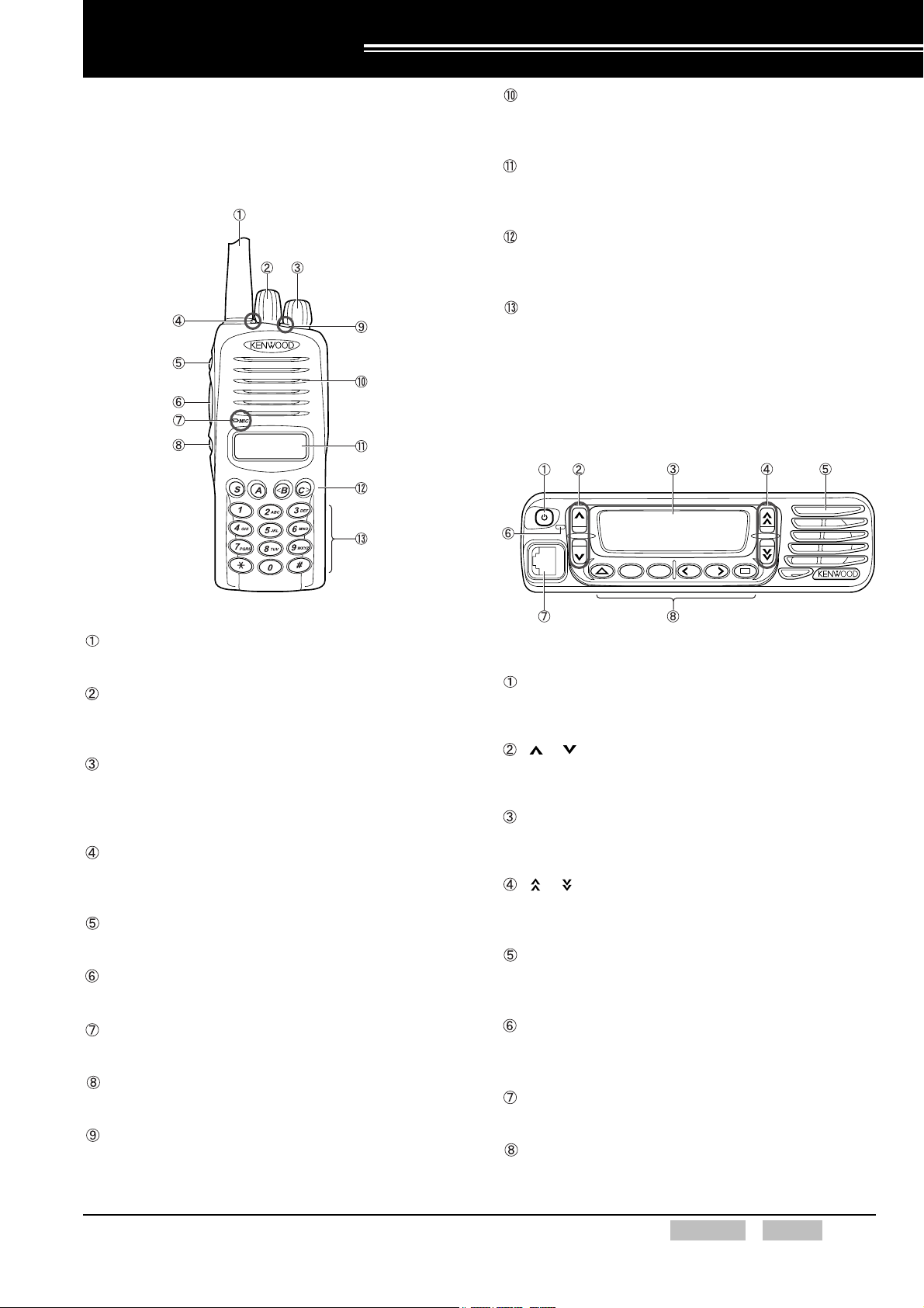
1 DESCRIPTION
1.1 Functions and Panel Layout
1.1.1 TK-2180/ TK-3180
Speaker
The speaker emits the received audio signals and
alert tones.
LCD Display
The channel number and the transceiver’s status
appear on this display.
PF Key
Press a PF key to activate the function assigned to
that function key.
Keypad
Press keys on the keypad to enter characters or
numbers. (The transceivers with a 12-key Keypad only)
1.1.2 TK-7180/ TK-7180H/ TK-8180/ TK-8180H
Figure 1-1 Front View of the TK-2180 and TK-3180
Antenna
This is the antenna of the transceiver.
Selector
This selector can be used to change the Call Address
or channel.
Power Switch/ Volume Control
Turn this switch to turn the transceiver ON.
The Volume control allows a user to adjust the
volume level from the speaker.
Transmit LED/ Busy LED
These LEDs light when the transceiver sends or
receives signals.
Side 1 Key
Press this key to activate the assigned function.
PTT Switch
Press the PTT switch to talk.
Microphone
Speak into the microphone to talk.
Side 2 Key
Press this key to activate the assigned function.
AUX Key
Press this key to activate the assigned function.
SA BC
Figure 1-2 Front View of the
TK-7180/ TK-7180H/ TK-8180/ TK-8180H
Power Switch
Press this switch to turn the transceiver ON and press
this switch again to turn the transceiver OFF.
[ ]/ [ ] Keys
These keys allow a user to adjust the volume level
from the speaker.
LCD Display
The channel number and the transceiver’s status
appear on this display.
[ ]/ [ ] Keys
These keys can be used to change the Call Address
or channel.
Speaker
The speaker emits the received audio signals and
Alert Tones.
Transmit LED/ Busy LED
These LEDs light when the transceiver sends or
receives signals.
Microphone Connector
A microphone can be connected to this connector.
PF Key
Press a PF key to activate the function assigned to
that function key.
FUNC (K)/Ver. 2.00 Confidential CONTENTS INDEX 1
1 DESCRIPTION
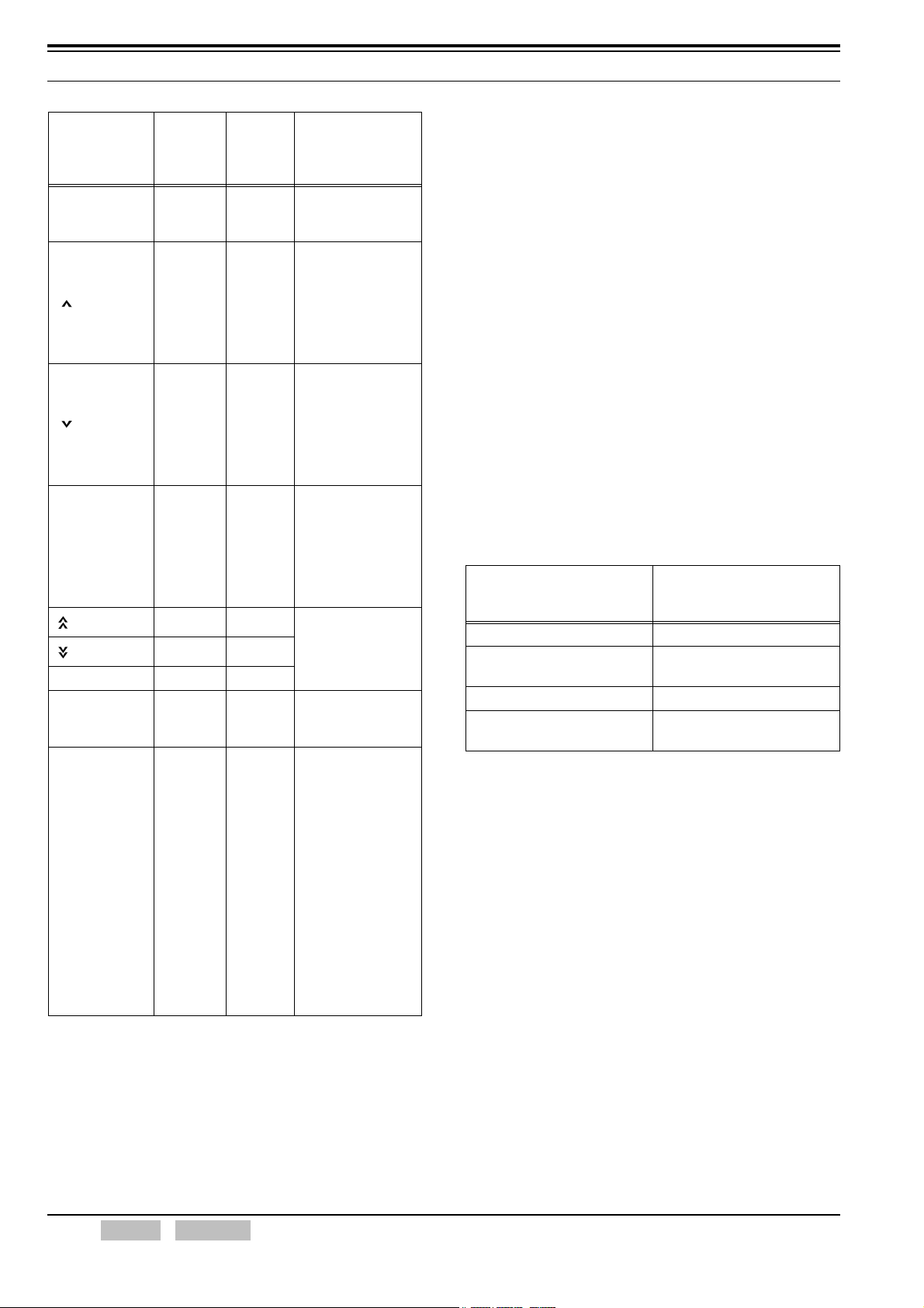
Table 1-1 Function Fixed Keys
TK-7180/
Key Name
Power Switch O -
[] Key
[] Key
Power Switch/
Vol ume Control
[] Key
[] Key
Selector -O
PTT Switch
Keypad
*1
Indicates keys on the external microphone.
TK-7180H/
TK-8180/
TK-8180H
O-
O-
O-
O-
*1
*1
TK-2180/
TK-3180
Turns the
transceiver
ON/ OFF.
Increases the
speaker volume.
Press and hold this
key for 1 second to
increase the volume
level by 1 step every
100 ms.
Decreases the
speaker volume.
Press and hold this
key for 1 second to
decrease the
volume level by
1 step every 100 ms.
Increases or
decreases the
speaker volume.
-O
This switch can also
be used to turn the
transceiver ON or
OFF.
Selects the target
party and status to
be sent.
Press this switch to
O
make a call and
communicate.
Enables dialing and
data entry in
MPT1343 and
DTMF transmission.
A 12-key or 16-key
microphone is
available if the
transceiver is
O
TK-7180/ TK-7180H/
TK-8180/ TK-8180H.
The 16-key keypad
has [A], [B], [C] and
[D] keys and these
keys can be
configured by using
KPG-96D.
Description
1.2 Description of MPT Trunking System
MPT stands for Ministry of Post and Telecommunication
and MPT Trunking Systems utilize signaling compliant
with MPT1327.
1200 bps FFSK is used as the signaling type in an MPT
Trunking System. The control channel is duplex (allowing
transmission and reception at the same time) and half
duplex control channels and full duplex control channels
are used for the transceiver. Dedicated type control
channels and undedicated type control channels can be
used. Communication takes place on the traffic channel.
1.3 Transmit and Receive Frequencies
This is a frequency pair used for transmitting and
receiving data.
Table 1-2 Transmit and Receive Frequencies
Transmit Frequency and
Model
TK-2180 136 to 174
TK-3180
TK-7180/ TK-7180H 136 to 174
TK-8180/ TK-8180H
Receive Frequency Range
[MHz]
400 to 470
450 to 520
400 to 470
450 to 520
1.4 Transmit Power
Low can be configured for the transmit power to reduce
battery consumption if the repeater or the receiving party
is nearby.
This configuration also extends the operating time of the
TK-2180/ TK-3180 transceiver.
Transmit power of the transceiver can be configured for
each channel in Conventional Mode by using KPG-96D.
Transmit power can be configured for the transceiver in
MPT Trunking System.
Following are the available transmit power settings.
2 INDEX CONTENTS Confidential FUNC (K)/Ver. 2.00
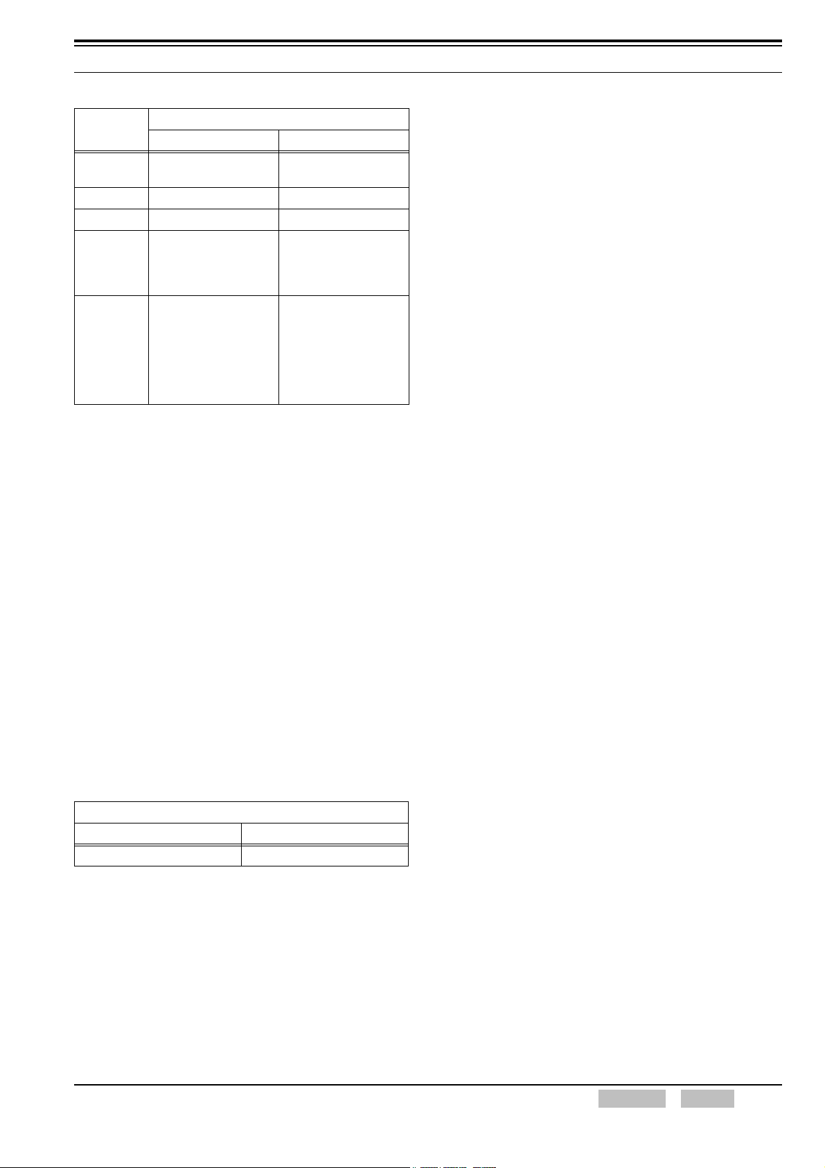
Table 1-3 Transmit Power: Low/ High
1 DESCRIPTION
Model
TK-2180/
TK-3180
TK-7180 30 5
TK-7180H 50 10
30: 400 to 490 MHz
TK-8180
TK-8180H
(including 490 MHz)
25: 490 to 520 MHz
(excluding 490 MHz)
45: 400 to 490 MHz
(490 MHz is included.)
40: 490 to 512 MHz
(490 MHz is excluded.
512 MHz is included.)
35: 512 to 520 MHz
(512 MHz is excluded.)
Transmit Power [W]
High Low
51
5
10
Configuration using KPG-96D
• Configuring the Transmit Power for each channel
(Refer to FPRG 6.3.9 Conventional (Channel)
Window.)
• Configuring the Transmit Power in MPT Trunking
System (Refer to FPRG 6.3.2 Trunking Features
Window.)
1.5 Channel Spacing
Channel Spacing is the channel bandwidth used for
communication.
Channel Spacing of the transceiver can be configured for
each channel in Conventional Mode by using KPG-96D.
Channel Spacing of the transceiver can be configured for
each network system in MPT Trunking System.
Table 1-4 Channel Spacing: Wide/ Narrow
Channel Spacing [kHz]
Wide Narrow
25 12.5
Configuration using KPG-96D
• Configuring the Channel Spacing (Wide or Narrow)
for each Channel (Refer to FPRG 6.3.9
Conventional (Channel) Window.)
• Configuring the Channel Spacing in MPT Trunking
System (Refer to FPRG 6.1.1 Network Information
Window.)
FUNC (K)/Ver. 2.00 Confidential CONTENTS INDEX 3

2 BASIC OPERATION
2.1 Turning the Transceiver ON/ OFF
2.1.1 Power ON
Turn the Power switch clockwise to turn ON the
transceiver if the transceiver is TK-2180 or TK-3180.
Press the Power switch to turn ON the transceiver if the
transceiver is TK-7180/ TK-7180H/ TK-8180/ TK-8180H.
The transceiver emits Power-on Tone for 500 ms when
the transceiver is turned ON and all LCD segments
appear. In this case, the transceiver checks for firmware
and available frequency data.
Turn the transceiver ON.
If no data is available
in the transceiver:
"UNPROGRAM" appears.
If MPT ESN is not correctly
configured:
"ESN ERROR" appears.
If MPT Trunking Option is not
correctly configured:
"UPG ERROR" appears.
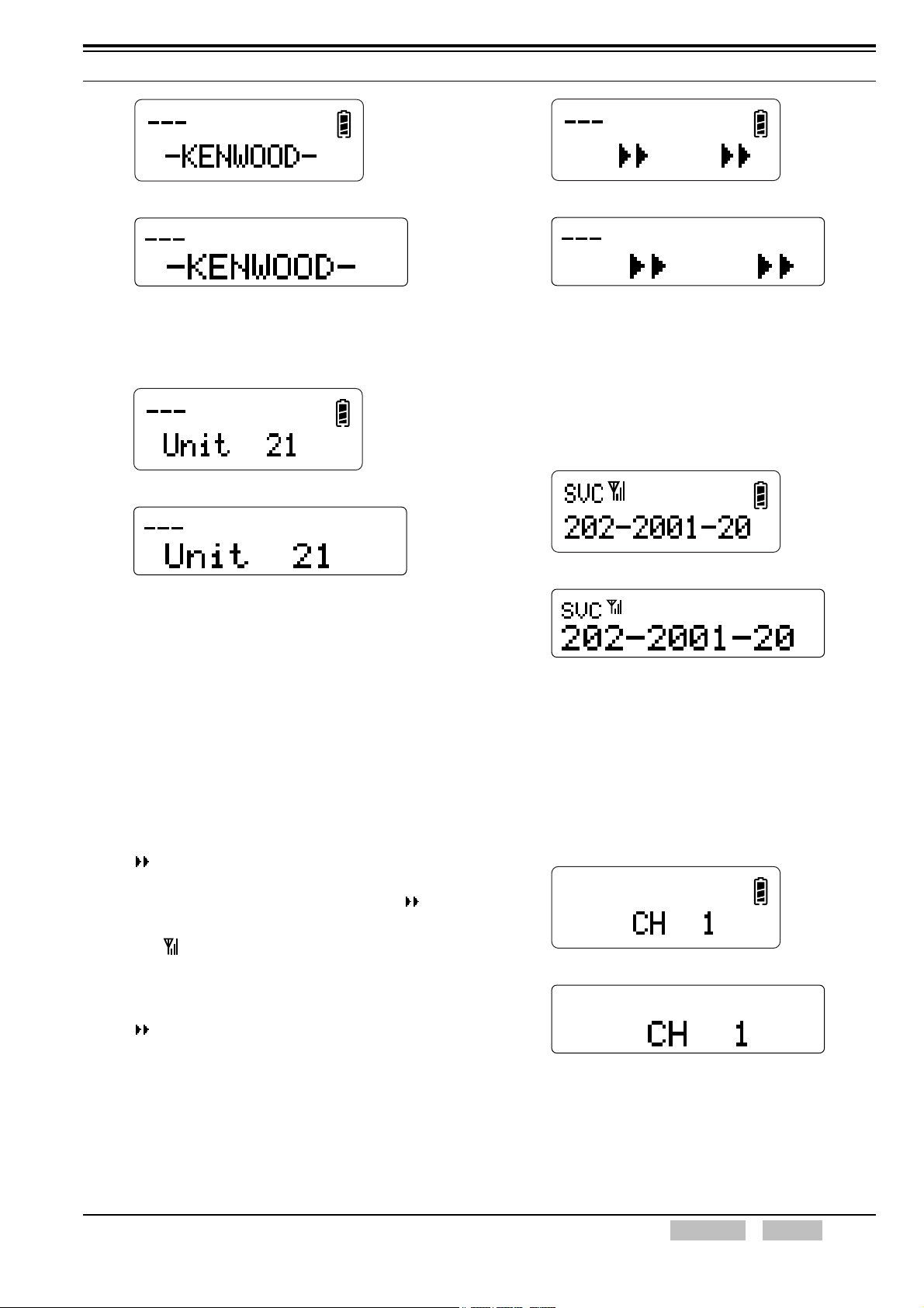
When available data exits
in the transceiver:
Display and Operation
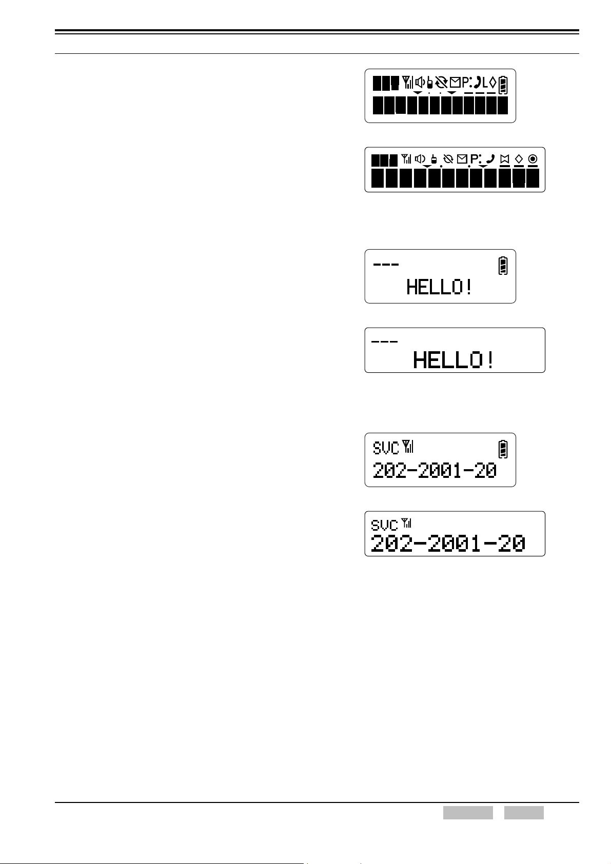
All Segments on the LCD Appear
z
The transceiver emits Power-on Tone A for 500 ms
when the transceiver is turned ON and all
segments on the LCD appear.
TK-2180/ TK-3180
TK-7180/ TK-7180H/ TK-8180/ TK-8180H
Note: Timed Power-off is disabled when the transceiver is
turned ON by pressing and holding the Power switch for
more than 1 second while Ignition Sense is configured
for “Ignition & Switch”. In this case, the transceiver
emits Power-on Tone B to notify a user that Timed
Power-off is disabled. (Refer to 7.2 Timed Power-off
(TK-7180/ TK-7180H/ TK-8180/ TK-8180H only) on
page 26.)
z Unprogram Display
“UNPROGRAM” appears on the main display if
there is no available data.
If the Transceiver Password
is configured:
"PASSWORD" appears.
(Refer to 5.1 Transceiver
Password on page 23.)
If the Power-on Text is
configured:
Display appearing while
searching a control
Call Address Name Display
Note: Transceiver operation may vary depending on the Power
Switch Status Memory configuration if the transceiver is
TK-7180/ TK-7180H/ TK-8180/ TK-8180H. (Refer to
2.1.3 Power Switch Status Memory (TK-7180/ TK-7180H/
TK-8180/ TK-8180H only) on page 6.)
If the Transceiver Password
is not configured:
* The Power-on Tone A
sounds for 500 ms.
* All LCDs light.
If the Power-on Text is not
configured:
The Unit Number appears
for 2 seconds.
TK-2180/ TK-3180
TK-7180/ TK-7180H/ TK-8180/ TK-8180H
z Power-on Text Display
If the Power-on Text is configured for the
transceiver, the message appears on the main
display for 2 seconds. (Refer to 3.6.4 Power-on
Text on page 17.)
4 INDEX CONTENTS Confidential FUNC (K)/Ver. 2.00
2 BASIC OPERATION
TK-2180/ TK-3180
TK-7180/ TK-7180H/ TK-8180/ TK-8180H
z Unit Number Display
The Unit Number appears on the main display for
2 seconds if no Power-on Message is configured.
TK-2180/ TK-3180
TK-7180/ TK-7180H/ TK-8180/ TK-8180H
Note: The clock appears on the display for 2 seconds if Clock
is configured for Power-on Message Type.
(Refer to 15.2 Power-on Clock Display on page 87.)
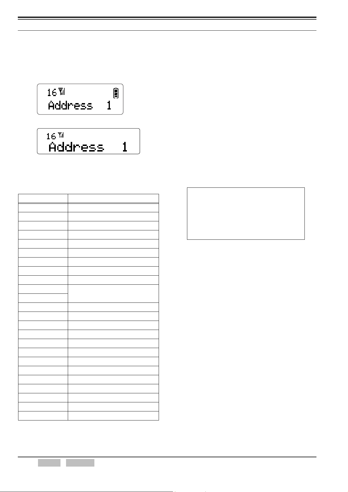
z Display Appearing while Searching a Control
Channel
When the Power-on Message display or Unit
Number display disappears, the transceiver
checks if an available control channel stored in
memory is available.
If the transceiver cannot find a control channel
stored in memory within a certain period, the
transceiver searches for another control channel.
TK-2180/ TK-3180
TK-7180/ TK-7180H/ TK-8180/ TK-8180H
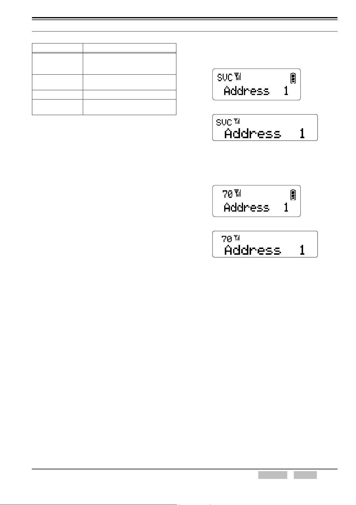
z Call Address Display
The Call Address Name (a maximum of 12
alphanumeric digits) configured for the transceiver
appears on the main display.
If no Call Address Name is configured for the
transceiver, “DR*” (* is a Call Address number)
appears on the display.
TK-2180/ TK-3180
TK-7180/ TK-7180H/ TK-8180/ TK-8180H
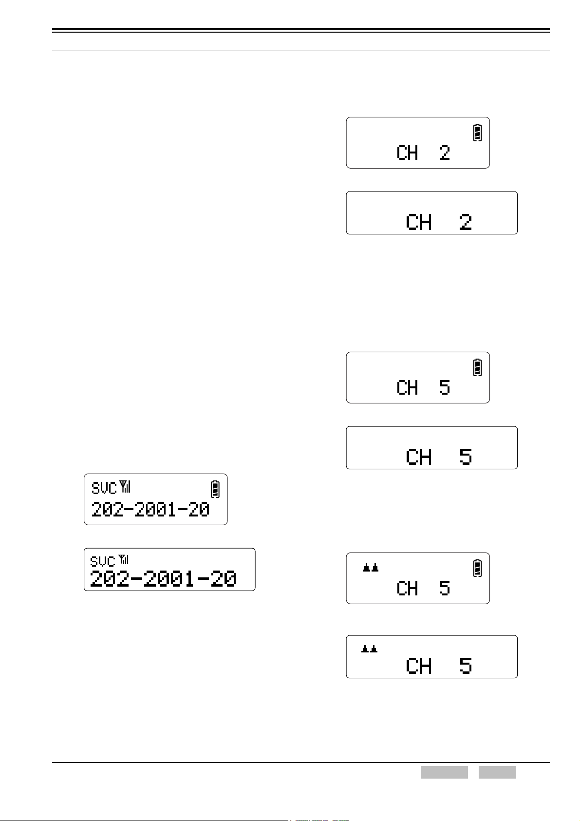
z Channel Name Display
When the transceiver is turned OFF and ON in
Conventional Mode, the Channel Name configured
for the transceiver appears on the main display
after displaying the Unit Number for 2 seconds.
If no Channel Name is configured for the
transceiver, “CH*” (* is a channel number) appears
on the main display.
“ ” scrolls from left to right on the main display if
the transceiver is searching for a control channel.
The transceiver cannot make a call while “ ” is
displayed.
The “ ” icon appears and the Call Address stored
in the transceiver memory appears on the display
TK-2180/ TK-3180
when an available control channel is found. “SVC”
appears on the sub display.
“ ” does not appear during registration.
The triangle mark starts scrolling when registration
fails.
TK-7180/ TK-7180H/ TK-8180/ TK-8180H
FUNC (K)/Ver. 2.00 Confidential CONTENTS INDEX 5

2 BASIC OPERATION
2.1.2 Power OFF
Turn the Power switch fully counterclockwise to turn OFF
the transceiver if the transceiver is TK-2180/ TK-3180.
Press the Power switch while the transceiver is turned
ON to turn OFF the transceiver if the transceiver is
TK-7180/ TK-7180H/ TK-8180/ TK-8180H.
Only the clock function works when the transceiver is
turned OFF.
2.1.3 Power Switch Status Memory
(TK-7180/ TK-7180H/ TK-8180/
TK-8180H only)
When the power connector is connected, this function
can be used to turn the transceiver ON or OFF in
conjunction with the Power switch status stored in the
transceiver.
Power Switch Status Memory can be configured to be
enabled or disabled by using KPG-96D.
Power Switch Status Memory Enabled
The transceiver turns ON and activates if the power
connector is removed while the transceiver is turned
ON, and then the connector is re-connected. The
transceiver remains OFF if the power connector is
removed while the transceiver is turned OFF, and
then the connector is re-connected. The transceiver
does not activate unless the Power switch is pressed.
Power Switch Status Memory Disabled
The transceiver is always turned ON when the power
connector is connected regardless of the transceiver
power status.
Note: Power Switch Status Memory does not work if Ignition
Sense is enabled.
Configuration using KPG-96D
• Configuring the Power Switch Status Memory to
be Enabled or Disabled (Refer to FPRG 6.4.1
Common Page 1 Tab >
Memory (TK-7180/ TK-7180H/ TK-8180/
TK-8180H only).)
Power Switch Status
2.1.4 Searching for Control Channel
Search for the control channel can be executed by
activating the following hunt sequence.
Hunt
This hunt sequence is enabled under the following
conditions:
• When the transceiver is turned ON.
• When the network is changed with Network Select.
• When Random Access fails.
The hunt sequence is enabled in the following order
and the transceiver can receive a control channel if
conditions are met at each hunt sequence.
Table 2-1 Hunt Sequence
Order Hunt Sequence Description
Resuming a Control
1
Channel Sequence
Single Channel Hunt
2
Sequence
Preferential Hunt
3
Sequence
Normal Hunt
4
Sequence
Comprehensive Hunt
5
Sequence
Note: Refer to the MPT-1343’s instruction manual for details of
the hunt sequences.
Background Hunt
This sequence is the hunt sequence executed by the
transceiver in the background.
If a possible channel is found in the Background Hunt,
the hunt sequences shown in Table 2-1 activate and
the tranceiver tries to receive the channel.
This sequence is used to resume
hunting for a control channel.
This sequence is used to receive
a single channel.
This sequence is a preferential
hunt sequence. This sequence
has the following 3 steps.
• Preferential NDD Sub-set Hunt
Stage
• Preferential Sampled Hunt
Stage
• Preferential Area Hunt Stage
This sequence is a normal hunt
sequence.
This sequence is a
comprehensive hunt sequence.
6 INDEX CONTENTS Confidential FUNC (K)/Ver. 2.00

2 BASIC OPERATION
Vote Now
This hunt sequence is enabled when the transceiver
receives the Vote Now Message (Broadcast
Message, SYSDEF = 00101) sent from the TSC. The
transceiver detects the level on the specified channel
when the transceiver receives a Vote Now Message
and receives a control channel.
Following hunt sequences are available in Vote Now:
Normal Vote Now and RegioNet43.
Conditions to receive a control channel vary
depending on the hunt sequence type.
Note: Refer to the Vote Now’s instruction manual for details of
the hunt sequence in Vote Now.
2.2 Adjusting the Volume
The volume level is increased when the Volume control
is turned clockwise and the level is decreased when the
Volume control is turned counterclockwise.
Press the [] key to increase the volume level from the
speaker and the [] key to decrease the volume level
from the speaker if the transceiver is TK-7180/ TK-7180H/
TK-8180/ TK-8180H.
2.3 Using Function Keys
Press any key to activate the function assigned to that
function key. (Refer to 11 KEY ASSIGNMENT on page
77.)
2.4 Changing the Call Address
Use the Selector, Call Address Up key or Call Address
Down key to change the Call Address in MPT Trunking
System. (Refer to 11 KEY ASSIGNMENT on page 77.)
The transceiver skips unregistered Call Addresses when
the Call Address is changed.
The Rollover Tone sounds when the smallest Call
Address is selected. (Refer to 4.1 Tone Patterns on page
18.)
Transceiver Operation
z Using the Selector (TK-2180/ TK-3180 only)
• Turn the Selector clockwise.
The Call Address number is increased by 1
step.
• Turn the Selector counterclockwise.
The Call Address number is decreased by 1
step.
z Using the PF Keys
• Press the Call Address Up key.
The Call Address number is increased by 1
step.
• Press and hold the Call Address Up key for
more than 1 second.
The Call Address number keeps increasing by
1 step every 200 ms.
• Press the Call Address Down key.
The Call Address number is decreased by 1
step.
• Press and hold the Call Address Up key for
more than 1 second.
The Call Address number keeps decreasing by
1 step every 200 ms.
Configuration using KPG-96D
• Assigning the Call Address Up and Call Address
Down to PF keys (Refer to FPRG 6.5 Key
Assignment Window.)
FUNC (K)/Ver. 2.00 Confidential CONTENTS INDEX 7

2 BASIC OPERATION
2.5 Changing the Channel
Use the Selector, Channel Up key or Channel Down
key to change the channel in Conventional Mode.
(Refer to 11 KEY ASSIGNMENT on page 77.)
Although the transceiver pauses scanning if the channel
is changed during the scan, the transceiver resumes
scanning after 1 second. (Refer to 10 SCAN on page 71.)
The transceiver skips unregistered channels if the
channel is changed.
The Rollover Tone sounds when the smallest channel is
selected. (Refer to 4.1 Tone Patterns on page 18.)
Transceiver Operation
z Using the Selector (TK-2180/ TK-3180 only)
• Turn the Selector clockwise.
The channel number is increased by 1 step.
• Turn the Selector counterclockwise.
The channel number is decreased by 1 step.
z Using the PF Keys
• Press the Channel Up key.
The channel number is increased by 1 step.
• Press and hold the Channel Up key for more
than 1 second.
The channel number keeps increasing by 1
step every 200 ms.
• Press the Channel Down key.
The channel number is decreased by 1 step.
• Press and hold the Channel Down key for
more than 1 second.
The channel number keeps decreasing by 1
step every 200 ms.
2.6 Receive
2.6.1 Receiving in MPT Trunking System
Refer to “8 MPT TRUNKING on page 27” for reception in
MPT Trunking System.
2.6.2 Receiving in Conventional Mode
The transceiver unmutes and emits the received audio
when the transceiver receives a carrier. If the QT/DQT
code is configured, the transceiver unmutes and emits
the received audio when the QT/DQT matches.
Receive Frequency and QT/DQT Decode must be
configured by using KPG-96D.
Transceiver Operation
1. Select the target channel. (Refer to 2.5 Changing
the Channel.)
2. Adjust the volume level if needed when the
transceiver receives a call. (Refer to 2.2 Adjusting
the Volume on page 7.)
Configuration using KPG-96D
• Configuring the Receive Frequency
(Refer to FPRG 6.3.9 Conventional (Channel)
Window.)
• Configuring the QT/DQT Decode (Refer to FPRG
6.3.9 Conventional (Channel) Window.)
Configuration using KPG-96D
• Assigning Channel Up and Channel Down to PF
keys (Refer to FPRG 6.5 Key Assignment
Window.)
8 INDEX CONTENTS Confidential FUNC (K)/Ver. 2.00
2 BASIC OPERATION
2.7 Transmit
2.7.1 Transmitting in MPT Trunking System
Refer to “8 MPT TRUNKING on page 27” for transmission
in MPT Trunking System.
2.7.2 Transmitting in Conventional Mode
The transceiver transmits voice when a user speaks while
pressing the PTT switch. When a QT/DQT is configured:
The transceiver sends the QT/DQT code when the PTT
switch is pressed to transmit. If the sent QT/DQT code
matches the QT/DQT code configured in the receiving
party’s transceiver, the caller can communicate with the
receiving party.
The transceiver sends Reverse Burst if QT is used or
sends the Turn-off code if DQT is used to mute the
speaker of the receiving party’s transceiver, when the
PTT switch is released.
Transmit Frequency and QT/DQT Encode not to sound a
Squelch tail, must be configured by using KPG-96D.
2. Press the Conventional key.
The transceiver enters Conventional Mode and the
previously selected channel name appears on the
main display.
TK-2180/ TK-3180
TK-7180/ TK-7180H/ TK-8180/ TK-8180H
Note: If the transceiver has exited from Conventional
Mode during the scan, the transceiver resumes
scanning.
3. Select a channel.
Select a channel using the Selector or Channel
Up or Channel Down key.
Display and Operation
1. Turn the transceiver ON.
The transceiver attempts to register an available
channel in MPT Trunking System. When the
registration completes, the Call Address appears
on the display.
TK-2180/ TK-3180
TK-7180/ TK-7180H/ TK-8180/ TK-8180H
Note: If the transceiver is turned OFF in Conventional Mode,
the transceiver stores the status in the memory. In this
case, the transceiver activates in Conventional Mode
when the transceiver is turned ON.
TK-2180/ TK-3180
TK-7180/ TK-7180H/ TK-8180/ TK-8180H
4. Press the PTT switch.
The transceiver transmits voice on the selected
channel.
LED lights red.
TK-2180/ TK-3180
LED lights red.
TK-7180/ TK-7180H/ TK-8180/ TK-8180H
FUNC (K)/Ver. 2.00 Confidential CONTENTS INDEX 9

2 BASIC OPERATION
Configuration using KPG-96D
• Configuring the Transmit Frequency
(Refer to FPRG 6.3.9 Conventional (Channel)
Window.)
• Configuring the QT/DQT Encode (Refer to FPRG
6.3.9 Conventional (Channel) Window.)
2.8 Mic PTT (TK-7180/ TK-7180H/ TK-8180/ TK-8180H only)
Mic PTT is the PTT switch on the KMC-35/ KMC-36
microphone. This switch can be used for normal
conversation.
Mic PTT can be configured by using KPG-96D.
The following functions are available for Mic PTT.
Note: Mic PTT is compliant with KMC-9C/ KMC-30/ KMC-32/
KMC-35/ KMC-36.
Connect to Modulation Line
Configure the modulation line for the Mic PTT.
Following is the modulation line list. The default
modulation line is the Mic line.
• Mic Line: The audio line of the Mic located on the
front of the transceiver
• MI2 Line: The audio modulation line of the D-sub
connector located on the rear of the transceiver
• DI Line: The data modulation line of the D-sub
connector located on the rear of the transceiver
With QT/DQT
Configure the QT/DQT for a Conventional channel to
be replaced when the transceiver sends code by a
user pressing the Mic PTT. Normally, only QT/DQT is
replaced.
Configuration using KPG-96D
• Configuring the Connect to Modulation Line
(Refer to FPRG 6.7.5 Modulation Line Tab
(TK-7180/ TK-7180H/ TK-8180/ TK-8180H only).)
• Configuring the With QT/DQT (Refer to FPRG
6.7.5 Modulation Line Tab (TK-7180/ TK-7180H/
TK-8180/ TK-8180H only).)
• Configuring the With STE (Refer to FPRG 6.7.5
Modulation Line Tab (TK-7180/ TK-7180H/
TK-8180/ TK-8180H only).)
2.9 Compander
This function improves the quality of the received audio
signal by reducing the amount of electrical noise.
It is used to improve the S/N ratio of voice
communications by compressing the audio of the
transmitting party at the transmit end of the
communication path and expanding the audio of the
receiving party at the receiving end.
Compander can be used in MPT Trunking System and
Conventional Mode.
Compander can be configured for normal voice
communications and voice communications using the
telephone line.
Compander can be configured to be enabled or disabled
by using KPG-96D. The transmitting party and the
receiving party must have the same configuration.
Configuration using KPG-96D
• Configuring the Compander (MPT Trunking) to be
Enabled or Disabled (Refer to FPRG 6.3.2
Trunking Features Window > Option 1 Tab.)
• Configuring the Compander (Conventional Mode)
to be Enabled or Disabled (Refer to FPRG 6.3.9
Conventional (Channel) Window.)
With STE
Configure the STE (Squelch Tail Eliminator) to be sent
after sending the QT/DQT code for a Conventional
channel by a user pressing the Mic PTT. Normally,
the transceiver sends STE.
10 INDEX CONTENTS Confidential FUNC (K)/Ver. 2.00
2 BASIC OPERATION
2.10 Key Lock (TK-2180/ TK-3180 only)
This function disables operation of the transceiver. This
is useful to prevent accidentally changing the transceiver
configuration while using a belt clip, etc.
Key Lock can be assigned to a PF key on the transceiver
by using KPG-96D.
Key Lock is enabled when the Key Lock key is pressed
and held for 1 second. Key Lock is disabled when the
Key Lock key is pressed and held for 1 second again.
Keys other than the PTT switch and Power switch cannot
be used while Key Lock is enabled.
The PF keys assigned with the following functions still
function even if Key Lock is enabled.
Conventional: Key Lock, Squelch Off, Lamp
MPT Trunking: Emergency, Lamp, Key Lock, Clear,
Call
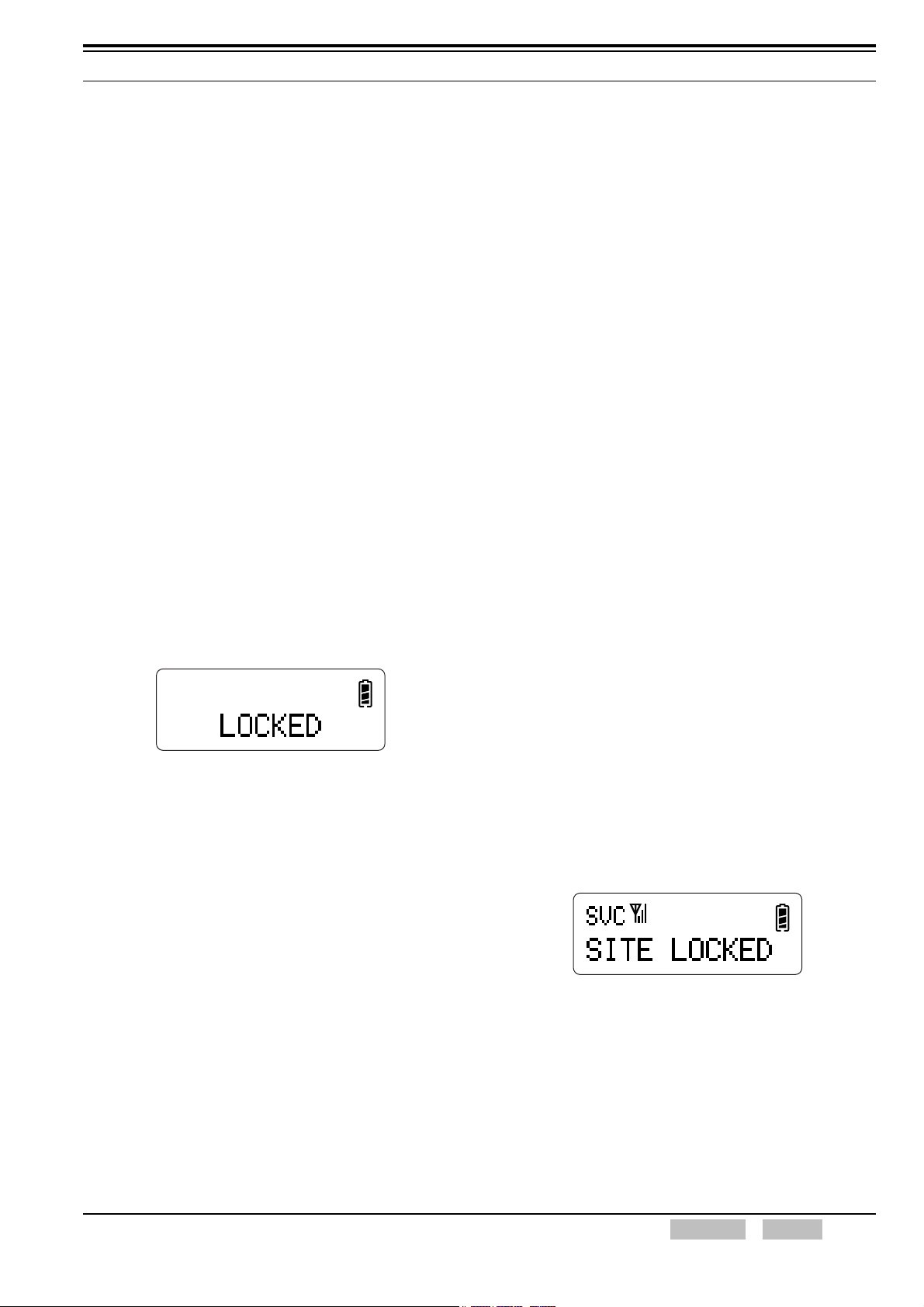
Display and Operation
“LOCKED” appears on the main display for 500 ms
and the Key-entry Error Tone sounds in the following
conditions:
• When pressing and holding the Key Lock key for
1 second.
• When pressing an inoperable key while Key Lock
is enabled.
TK-2180/ TK-3180
Note:
The Key Lock status is stored in the memory even if the
transceiver is turned OFF.
Transceiver Password is enabled before Key Lock is
enabled if the Transceiver Password is configured. Key
Lock is enabled when Transceiver Password is disabled.
2.11 Keypad Operation
Keypad Operation can be configured according to the
usage of the transceiver.
Dialing codes and DTMF codes can be directly entered
using the keypad.
This function can be enabled only if a keypad is equipped
on the TK-2180 or TK-3180.
This function can be enabled when 12-key or 16-key is
configured for Mic Keypad by using KPG-96D if the
transceiver is TK-7180/ TK-7180H/ TK-8180/
TK-8180H.
Keypad Operation can be configured by using KPG-96D.
Configuration using KPG-96D
• Configuring the Keypad Operation
(Refer to FPRG 6.5 Key Assignment Window.)
2.12 Site Lock
Site Lock can be used to remain on the current control
channel.
When Site Lock is enabled, the transceiver remains on
the current control channel even if a control channel
having higher signal strength is detected. If Site Lock is
disabled, the transceiver jumps to another control
channel when a control channel having higher signal
strength is detected.
Site Lock can be assigned to a PF key on the transceiver
by using KPG-96D.
Display and Operation
1. Press and hold the Site Lock key for 1 second.
The transceiver is locked on the current site.
“SITE LOCKED” appears on the main display for
500 ms and the Key Beep A sounds.
Configuration using KPG-96D
• Assigning the Key Lock to a PF Key
(Refer to FPRG 6.5 Key Assignment Window.)
TK-2180/ TK-3180
2. Press and hold the Site Lock key for 1 second
again.
Site Lock is disabled. In this case, the Key Beep B
sounds.
FUNC (K)/Ver. 2.00 Confidential CONTENTS INDEX 11
3 DISPLAY
The transceiver has the following displays and indicators.
• LED (Transmit/ Busy)
• LCD Display
3.1 Busy LED
The Busy LED is used to notify a user that the transceiver
is receiving a carrier. The Busy LED lights green when
the transceiver receives a carrier.
Note: This function is only available in Conventional Mode.
The Busy LED does not light in MPT Trunking System.
3.2 Transmit LED
The Transmit LED is used to notify a user that the
transceiver is transmitting. The Transmit LED lights red
while the transceiver is transmitting.
TK-7180/ TK-7180H/ TK-8180/ TK-8180H
Sub display Icon display area
Main display
Figure 3-2 TK-7180/ TK-7180H/ TK-8180/ TK-8180H
LCD Display
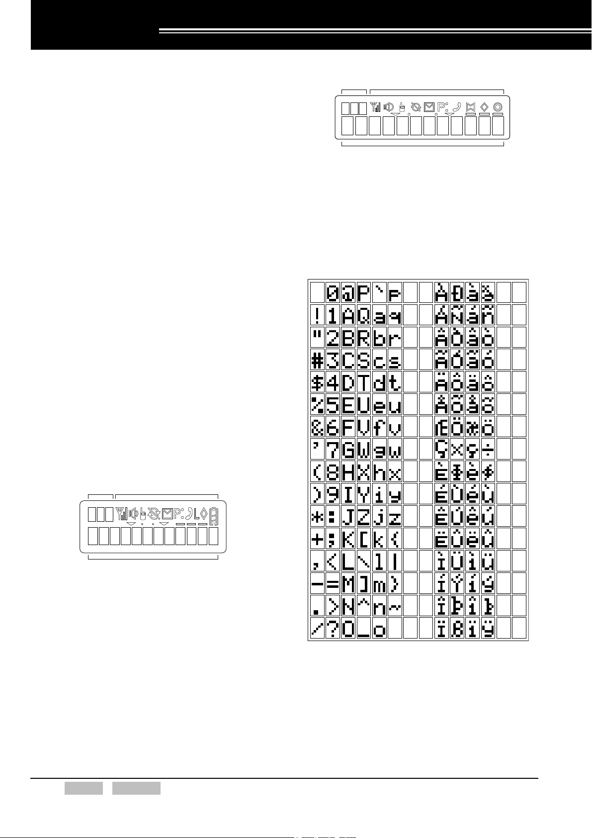
3.3.1 Available Characters on the Main Display and Sub Display
The following characters are available on the main
display and sub display.
3.3 LCD Display
The following displays are available.
TK-2180/ TK-3180
Sub display Icon display area
Main display
Figure 3-1 TK-2180/ TK-3180 LCD Display
Figure 3-3 Available Characters on the Main Display and
Sub Display
12 INDEX CONTENTS Confidential FUNC (K)/Ver. 2.00
3 DISPLAY
3.3.2 Lamp (TK-2180/ TK-3180 only)
The backlight LEDs are located behind the LCD and the
front keypad. With this function, a user can view the LCD
in dark places or at night by using the backlight LEDs.
The LEDs light in the following conditions.
Pressing the Lamp Key
When the Lamp key is pressed, the backlight LED
lights.
Using the Auto Backlight Functions
The backlight LED lights when a key other than the
PTT switch or Volume control is used while Auto
Backlight is enabled.
Note:
The backlight LED lights for 5 seconds and automatically turns
Off if no key is pressed after the backlight LED turns On.
The illumination time is updated every time a key is pressed
while the backlight LED is lit and the illumination time of the
backlight LED extends for 5 seconds.
The backlight LED turns Off when the Lamp key is pressed
while the backlight light LED is lit.
Configuration using KPG-96D
• Assigning the Lamp Function to a PF key
(Refer to FPRG 6.5 Key Assignment Window.)
• Configuring the Auto Backlight to be Enabled or
Disabled (Refer to FPRG 6.4 Optional Features
Window > 6.4.1 Common Page 1 Tab.)
3.3.3 LCD Brightness (TK-7180/ TK-7180H/ TK-8180/ TK-8180H only)
With this function, a user can decrease the brightness of
the backlight LED when using the transceiver in dark
places or at night. When the LCD Brightness key is
pressed, the brightness of the backlight LED changes.
The brightness changes in the following order: High
Low Off.
The brightness status of the backlight configured by using
the LCD Brightness key is retained even if the
transceiver is turned OFF.
The brightness of the backlight LED can be configured
using KPG-96D.
Configuration using KPG-96D
• Assigning the LCD Brightness to a PF key
(Refer to FPRG 6.5 Key Assignment Window.)
• Configuring the LCD Brightness Level
(Refer to FPRG 6.4 Optional Features Window >
6.4.1 Common Page 1 Tab.)
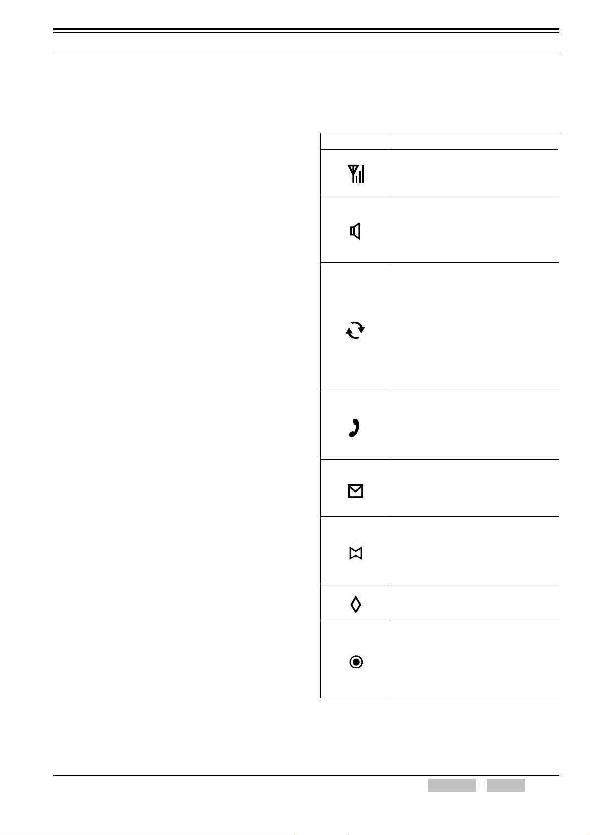
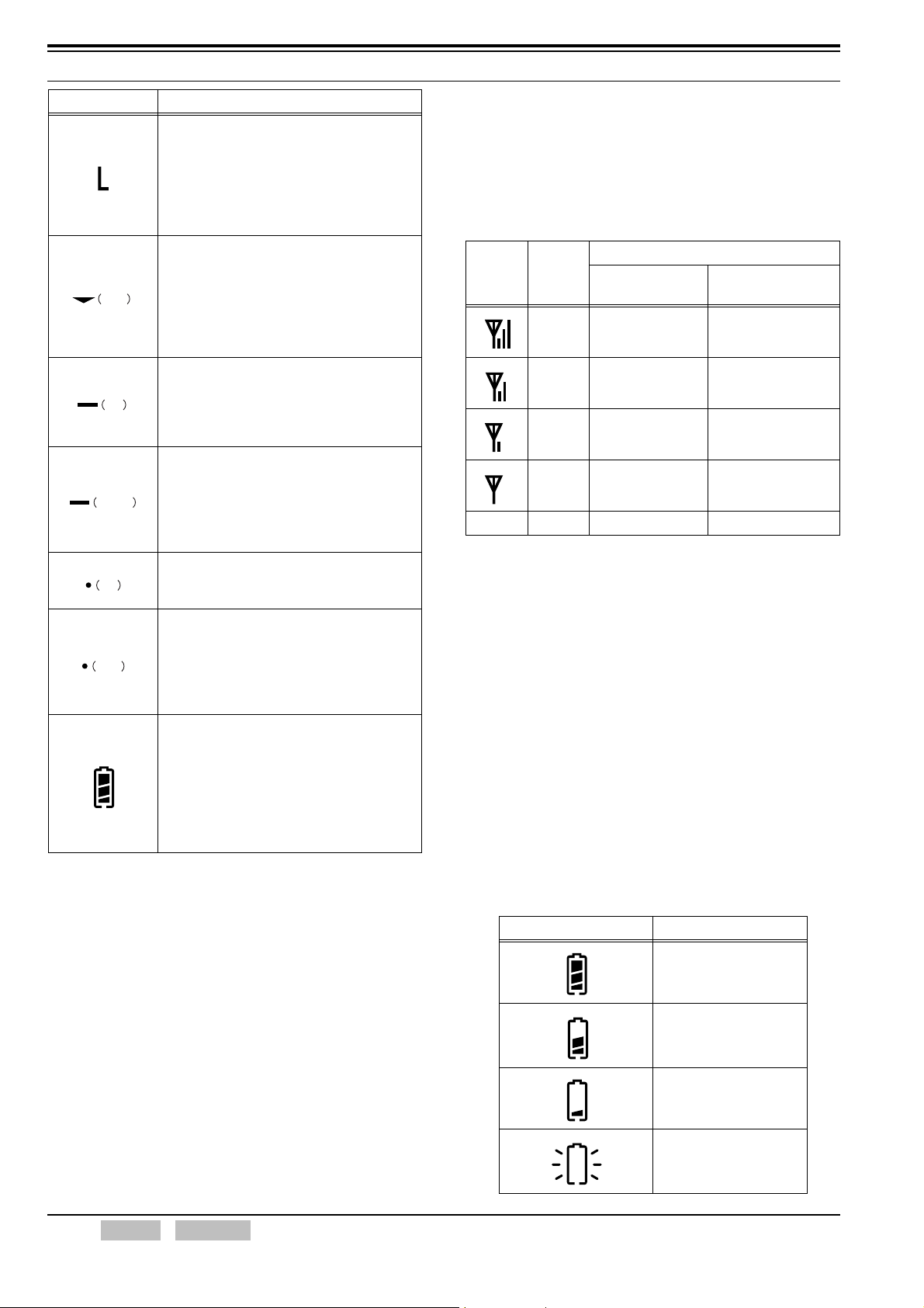
3.4 Icons
The following icons indicate the transceiver’s status.
Each icon appears in the icon display area of the LCD.
Table 3-1 Icon List
Icons Function
• RSSI Icon
Displays the received signal level (RSSI).
This icon does not appear while searching
for a control channel.
• Monitor Open Icon
Conventional:
This icon indicates the transceiver’s
status while Squelch Off is enabled.
MPT Trunking System:
Not used
• Scan Mode Icon
Conventional:
This icon indicates the scan status.
The Scan Mode icon has 2 statuses.
Solid: The transceiver is scanning or has
paused scanning while scanning.
Flashing: When the scan is disabled
while the transceiver is in Scan
Mode.
MPT Trunking System:
Solid: The transceiver is doing a group
scan.
• Telephone ID Icon
Conventional:
Not used
MPT Trunking System:
Flashing: When Own Call Diversion is
enabled.
• Message Stack Icon
This icon indicates Message Stack status.
The Message Stack icon has 2 statuses.
Solid: When a message is stacked.
Flashing: When a new message is stored.
• Horn Alert Icon (TK-7180/ TK-7180H/
TK-8180/ TK-8180H only)
Conventional:
Not used
MPT Trunking System:
This icon indicates the Horn Alert state.
• Scrambler Icon
This icon indicates the status of
Scrambler.
• Public Address Icon (TK-7180/ TK-7180H/
TK-8180/ TK-8180H only)
Conventional:
Not used
MPT Trunking System:
This icon indicates the status of Public
Address.
FUNC (K)/Ver. 2.00 Confidential CONTENTS INDEX 13
3 DISPLAY
Icons Function
• Low Transmit Power Icon (TK-2180/
TK-3180 only)
Conventional:
This icon indicates the status of Low
Transmit Power.
MPT Trunking System:
Not used
• Scan Channel Add Icon
Conventional:
This icon indicates the status of Scan
right
left
center
left
right
Channel Add.
MPT Trunking System:
This icon indicates the status of Group
Scan ID Add.
• AUX A Icon
Conventional:
Not used
MPT Trunking System:
This icon indicates the AUX A status.
• AUX B/ AUX Icon
Conventional:
Not used
MPT Trunking System:
This icon indicates the status of
AUX B and AUX.
• Auto Recording Icon
This icon indicates the status of Auto
Recording.
• Auto Reply Message Icon
Conventional:
Not used
MPT Trunking System:
This icon appears when the transceiver
is in Auto Reply Message Mode.
• Battery Indicator Icon (TK-2180/ TK-3180
only)
This icon indicates the status of Battery
Indicator.
The Battery Indicator icon has 3 statuses.
Solid: High, Sufficient, Low
Flashing: Very Low
Off: When alkaline batteries are used.
3.4.1 Signal Strength Indicator
This function is used to indicate the received signal
strength at the transceiver.
When this function is enabled, the signal strength of the
received signal appears.
Table 3-2 Signal Strength
Signal Strength (dBm)
Icons Status
High Above -80 Above -74
Medium -95 to -80 -92 to -74
Low -110 to -95 -110 to -92
Very
weak
None No signal No carrier No carrier
Note: Value shown represents signal strengths as measured at
room temperature.
TK-2180/ TK-3180
When a carrier is
detected to -110
TK-7180/ TK-7180H/
TK-8180/ TK-8180H
When a carrier is
detected to -110
3.4.2 Battery Status/ Warning (TK-2180/ TK-3180 only)
This function is used to indicate the remaining battery life
of the transceiver battery.
When Battery Status is enabled, the battery status is
displayed in 4 stages according to the remaining battery
capacity.
If Battery Warning is enabled, the transceiver emits a
beep or displays a warning message if the battery voltage
level is low.
Battery Status/ Warning can be configured to be enabled
or disabled by using KPG-96D.
Table 3-3 Battery Status Icon List
Icons Status
High
Sufficient
Low
Very Low
14 INDEX CONTENTS Confidential FUNC (K)/Ver. 2.00
3 DISPLAY
Table 3-4 Battery Warning Operations
Battery Warning Operation
Transmits as usual and no battery
Off
While Transmitting
Always The LED flashes red continuously.
Always with Beep
Note:
The status of alkaline batteries cannot be displayed.
The transceiver operates in conjunction with the “While
Transmitting” configuration if “Always” or “Always with Beep” is
selected while alkaline batteries are used.
warning is given regardless of battery
voltage status.
The LED flashes red while the
transceiver is transmitting.
The LED flashes red continuously and
the Battery Warning Tone sounds.
Configuration using KPG-96D
• Configuring the Battery Warning (Refer to FPRG
6.4 Optional Features Window > 6.4.2 Common
Page 2 Tab.)
• Configuring the Battery Status (Refer to FPRG 6.4
Optional Features Window > 6.4.2 Common Page
2 Tab.)
Display and Operation
z SVC Display
Normally, “SVC” appears on the sub display.
TK-2180/ TK-3180
TK-7180/ TK-7180H/ TK-8180/ TK-8180H
z Signal Strength (dBm) Display
The signal strength (dBm) appears on the sub
display if Signal Strength Level is configured.
TK-2180/ TK-3180
3.5 Sub-LCD Display
A maximum of 3 alphanumeric digits can be displayed on
the sub display.
Normally, “SVC” appears on the sub display.
When the Sub-LCD Display key is pressed, the sub
display switches in the following order: SVC display
Signal Strength display [dBm] Control Channel display
or Traffic Channel display.
Sub-LCD Display can be assigned to a key on the
transceiver by using KPG-96D.
Note: This function is only available in MPT Trunking System.
TK-7180/ TK-7180H/ TK-8180/ TK-8180H
The signal strength appears on the sub display
depending on the signal strength level of the
received signal.
• When the signal strength level of the
received signal is between -120 dBm to
-70 dBm.
A value between “120” (-120 dBm) and “70”
(-70 dBm) appears on the sub display in steps
of 1 dBm every 500 ms.
• When the signal strength level of the
received signal is less than -120 dBm.
“> - -” appears on the display.
• When the signal strength level of the
received signal is larger than -70 dBm.
“>70” appears on the display.
FUNC (K)/Ver. 2.00 Confidential CONTENTS INDEX 15
3 DISPLAY
z Control Channel Display or Traffic Channel
Display
The control channel number appears on the sub
display when a control channel is used and the
traffic channel number appears when a traffic
channel is used.
TK-2180/ TK-3180
TK-7180/ TK-7180H/ TK-8180/ TK-8180H
The following characters appear on the sub display
depending on the specific situation.
Table 3-5 Sub Display List
Sub Display Function
00 to 31 Status No.
R01 to R03 Redial No.
N1 to N8 Network No.
01 to 32 Stack No.
EMG Emergency Call Display (Flash)
CAL Individual Call Display (Flash)
GRP Group Call Display (Flash)
BCC Broadcast Message Display (Flash)
NEW New Status Display
SS
S
HAD Home Address
V01 VGS Recording Mode
ID Own Prefix, Fleet, Ident Display
CNM Control Channel Select
CH Current Control Channel Number
SYS Current System
CEC Codeword Error Counter
B V Beep Volume
R V Ringer Volume
SIL Speaker Mute
LMP Lamp (TK-2180/ TK-3180 only)
C D Current Traffic Channel Number
GR1 to GR7 Temporary Receive/Transmit Group
Transmit Power Display
(SS: High, S: Low)
Configuration using KPG-96D
• Assigning the Sub-LCD Display to a PF key
(Refer to FPRG 6.5 Key Assignment Window.)
3.6 Main Display
The following items relevant to the main display can be
configured:
• Network Name
• Personal Name
• Channel Name
• Power-on Text
Note: The following alphanumeric digits and symbols can be
entered using KPG-96D.
Table 3-6 Available Characters using KPG-96D
0 1 2 3 4 5 6 7 8 9 A B C D E F G H I J K L M N O P
Q R S T U V W X Y Z a b c d e f g h i j k l m n o p q r
s t u v w x y z
À Á Â Ã Ä Å Æ Ç È É Ê Ë Ì Í Î Ï Ð Ñ Ò Ó Ô Õ Ö × Ø
Ù Ú Û Ü Ý Þ ß à á â ã ä å æ ç è é ê ë ì í î ï ð ñ ò ó ô
õ ö ÷ ø ù ú û ü ý þ ÿ
! " # $ % & ' ( ) ~ + - , . / : ; < = > ? @ [ \ ] ^ _ ` { } * |
(space)
3.6.1 Network Name
Network Name can be used to assign a name to the
network. Normally, these icons only appear in the
KPG-96D window.
A maximum of 12 alphanumeric digits can be configured
for each network.
Network Name can be configured by using KPG-96D.
Configuration using KPG-96D
• Configuring the Network Name (Refer to FPRG
6.1.1 Network Information Window.)
16 INDEX CONTENTS Confidential FUNC (K)/Ver. 2.00
3.6.2 Personal Name
Personal Name can be used to assign a name to
personal data. This function is only available in MPT
Trunking System.
The personal name appears on the main display when
selecting a network by using the Network Select key.
A maximum of 12 alphanumeric digits can be configured
for each personal data.
Personal Name can be configured by using KPG-96D.
Configuration using KPG-96D
• Configuring the Personal Name (Refer to FPRG
6.3.1 Personalization Window.)
3.6.3 Channel Name
3 DISPLAY
TK-2180/ TK-3180
TK-7180/ TK-7180H/ TK-8180/ TK-8180H
The configured text appears for 2 seconds after all
segments on the LCD disappear.
Channel Name can be used to assign a name to a
channel. The function is only available in Conventional
Mode.
A maximum of 12 alphanumeric digits can be configured
for each channel. Channel Name can be assigned to
allow easy recognition of each channel.
Channel Name can be configured using KPG-96D.
Configuration using KPG-96D
• Configuring the Channel Name (Refer to FPRG
6.3.9 Conventional (Channel) Window.)
3.6.4 Power-on Text
Power-on Text can be used to display characters on the
display when the transceiver is turned ON.
The message configured for Power-on Text appears for
2 seconds after the transceiver is turned ON.
Power-on Text can be configured using KPG-96D.
Display and Operation
1. Turn the transceiver ON.
Power-on Tone A sounds for 500 ms when the
transceiver is turned ON and all segments on the
LCD appear.
TK-2180/ TK-3180
TK-7180/ TK-7180H/ TK-8180/ TK-8180H
When the registration completes, the Call Address
appears on the main display.
TK-2180/ TK-3180
TK-7180/ TK-7180H/ TK-8180/ TK-8180H
Configuration using KPG-96D
• Configuring the Power-on Text (Refer to FPRG
6.4 Optional Features Window > 6.4.2 Common
Page 2 Tab.)
FUNC (K)/Ver. 2.00 Confidential CONTENTS INDEX 17

4 SOUNDS
4.1 Tone Patterns
The transceiver emits the following tones.
Table 4-1 Tone List
Ton e Type Type
Power-on Tone A
Power-on Tone
Control Tone
Warning Tone
Reception Tone Phone Tone
MPT Tone
Transpond Tone Transpond Tone
Locator Tone Locator Tone
4.1.1 Power-on Tone
The transceiver emits this tone when the transceiver is
turned ON.
Function Description
Power-on Tone A
Power-on Tone B
(TK-7180/ TK-7180H/
TK-8180/ TK-8180H only)
Power-on Tone B (TK-7180/ TK-7180H/
TK-8180/ TK-8180H only)
Key Beep A
Key Beep B
Key Beep C
Key-entry Error Tone
Rollover Tone
Warning Alert Tone
TOT Pre-alert Tone
Battery Warning Tone (TK-2180/ TK-3180
only)
Stack in Tone
Stack Alert Tone A/ B
Pre-alert
Timed Power-off Pre-alert
Trunking Tone
PLL Unlock Tone
CSUIP (Calling)/ Call Queued Tone
(Tone A)
Called Party Ringing Tone (Tone B)
System Busy Tone (Tone C)
Unavailable Tone (Tone D)
Called Party Busy Tone (Tone E)
Number Unobtainable Tone (Tone F)
Call Clear Indication Tone (Tone H)
Alert Tone (Tone I)
Transaction Confirmed Tone (Tone J)
GTC Blip Tone (Tone K)
Table 4-2 Power-on Tone List
The transceiver emits this tone
when the transceiver is turned
ON.
The transceiver emits this tone
to notify a user that Timed
Power-off is disabled when the
transceiver is turned ON by
pressing and holding the Power
switch for more than 1 second.
4.1.2 Control Tone
The transceiver emits this tone when a function activates.
Table 4-3 Control Tone List
Function Description
The transceiver emits this tone when
Key Beep A
Key Beep B
Key Beep C
Key-entry Error Tone
Rollover Tone
a function is enabled by pressing a
key.
The transceiver emits this tone when
a function is disabled by pressing a
key.
The transceiver emits this tone when
the password matches or data, such
as Test Mode adjustment value, is
written to the transceiver by pressing
a key.
The transceiver emits this tone when
the operation activated by pressing a
key is denied.
The transceiver emits this tone when
a key with no function assigned or
an inoperable key is pressed.
The transceiver emits this tone when
the smallest Call Address number or
channel number is selected.
4.1.3 Warning Tone
The transceiver emits this tone to warn a user.
Table 4-4 Warning Tone List
Function Description
The transceiver emits this tone until
the PTT switch is released if
transmission is restricted with the
Time-out Timer or there is no
Warning Alert Tone
TOT Pre-alert Tone
Battery Warning Tone
(TK-2180/ TK-3180 only)
Stack in Tone
Stack Alert Tone A/ B
Pre-alert
transmit frequency. The transceiver
emits this tone until the PTT switch
is released while Busy Channel
Lockout is enabled in Conventional
Mode.
The transceiver emits this tone to
notify a user that the transmission is
going to be restricted by the Timeout Timer.
The transceiver emits this tone when
the battery level reaches low.
The transceiver emits this tone when
a message is stored.
The transceiver emits this tone when
an unread message is stored.
The transceiver emits this tone to
notify a user that the transmission is
going to be restricted in MPT
Trunking System.
18 INDEX CONTENTS Confidential FUNC (K)/Ver. 2.00

4 SOUNDS
Function Description
The transceiver emits this tone to
Timed Power-off
Pre-alert
Trunking Tone
PLL Unlock Tone
notify a user that the transceiver is
going to be turned OFF by Timed
Power-off.
The transceiver emits this tone when
a control channel is found during the
Trunking Search.
The transceiver emits this tone when
the PLL circuit is unlocked.
4.1.4 Reception Tone
The transceiver emits this tone when the transceiver
receives a call.
Table 4-5 Reception Tone List
Function Description
Phone Tone
The transceiver emits this tone when
the transceiver receives a call.
4.1.5 MPT Tone
Function Description
The transceiver emits this tone when
Transaction Confirmed
Tone (Tone J)
GTC Blip Tone (Tone K)
the transceiver receives an ACK
corresponding to a transaction
executed for the TSC.
The transceiver emits this tone when
the transceiver receives a GTC
message from the TSC.
4.1.6 Transpond Tone
When an available channel for the Auto Reply Message is
found, the transceiver sends a Greeting Message (I am
not available. Leave your message.) and transmits the
Transpond Tone (2100 Hz) for 1 second. The transceiver
only modulates this tone and does not emit the tone from
the speaker.
4.1.7 Locator Tone
The transceiver emits this tone before the transceiver
transmits or receives in Emergency Mode.
The transceiver emits the following tones in MPT
Trunking System.
Table 4-6 MPT Tone List
Function Description
The transceiver emits these tones
CSUIP (Calling)/ Call
Queued Tone (Tone A)
Called Party Ringing
Tone (Tone B)
System Busy Tone
(Tone C)
Unavailable Tone
(Tone D)
Called Party Busy Tone
(Tone E)
Number Unobtainable
Tone (Tone F)
Call Clear Indication
Tone (Tone H)
Alert Tone (Tone I)
when the transceiver of the
transmitting party is in CSUIP or the
transceiver is waiting to receive a
call.
The transceiver emits this tone when
the transceiver receives ACKI
(QUAL ‘0’) from TSC.
The transceiver emits this tone when
the transceiver receives a message
indicating a system overload from
the TSC.
The transceiver emits this tone when
the receiving party does not respond.
The transceiver emits this tone when
the transceiver receives a message
indicating a call failure from the TSC.
The transceiver emits this tone to
notify a user that a dialing cannot be
identified or processed.
The transceiver emits this tone to
clear a call.
The transceiver emits this tone to
warn a user.
4.2 Minimum Volume
The Minimum Volume function differs between the
TK-2180/ TK-3180 and TK-7180/ TK-7180H/ TK-8180/
TK-8180H transceivers.
Minimum Volume can be configured by using KPG-96D.
TK-2180/ TK-3180
This function can be used to limit the minimum volume
level if the volume control is turned to its lowest level.
With this function, the user can hear communication
even if the Vol ume control is unintentionally turned to
its lowest level. The volume level does not change
from most counterclockwise position configured for
Minimum Volume. The transceiver mutes completely
if the Vol ume control is turned to the most
counterclockwise position while Minimum Volume is
not configured.
FUNC (K)/Ver. 2.00 Confidential CONTENTS INDEX 19
4 SOUNDS
TK-7180/ TK-7180H/ TK-8180/ TK-8180H
z When Preset is configured for Minimum
Volume Type:
This function can be used to configure the
Minimum Volume level for the volume level when
the transceiver is turned ON even if the volume
level was completely turned down and the
transceiver was turned Off.
z When Lowest Limit is configured for Minimum
Volume Type:
This function can be used to limit the minimum
volume level if the Vol ume control is turned to its
lowest level. With this function, a user can hear
communication even if the Vol ume control is
unintentionally turned to its lowest level. The
volume level increases from the Minimum Volume
Level when turning the Volume control. The
transceiver mutes completely if the Volu me control
is turned to the most counterclockwise position
while Minimum Volume is not configured.
Configuration using KPG-96D
• Configuring the Minimum Volume (Refer to FPRG
6.4 Optional Features Window > 6.4.2 Common
Page 2 Tab.)
• Configuring the Minimum Volume Type
(Refer to FPRG 6.4 Optional Features Window >
6.4.2 Common Page 2 Tab.)
4.4 Tone Level
Tone Level can be used to configure the tone volume.
The transceiver emits tones from the speaker at the
configured volume level.
Tone Level can be configured by using KPG-96D.
The following Tone Levels are available.
Table 4-7 Available Tone Levels
Tone Level Operation
Current
1 to 31
Off The transceiver does not emit any tones.
The transceiver emits tones in conjunction
with the volume level.
The transceiver emits tones with a fixed
tone volume. Larger values result in greater
volume.
Configuration using KPG-96D
• Configuring the Tone Level (Refer to FPRG 6.4
Optional Features Window > 6.4.1 Common Page
1 Tab.)
4.5 Pre-alert (MPT Trunking)
4.3 Maximum Volume (TK-2180/ TK-3180 only)
Maximum Volume restricts the volume level so as not to
exceed the configured volume even if a user attempts to
increase the volume.
This function prevents the user from hearing excessively
loud volume levels when wearing a headset.
Maximum Volume can be configured by using KPG-96D.
Configuration using KPG-96D
• Configuring the Maximum Volume (Refer to FPRG
6.4 Optional Features Window > 6.4.2 Common
Page 2 Tab.)
This function can be used to notify a user that
communication is going to be terminated while the user is
communicating in MPT Trunking System. This function is
only available in MPT Trunking System.
Pre-alert can be configured to be enabled or disabled by
using KPG-96D.
The transceiver emits Alert Tones under the following
conditions if Pre-alert is enabled.
Table 4-8 Timings for Pre-alert Tones
Timing Operation
30 seconds before the
communication is
terminated
6 to 10 seconds before
the communication is
terminated
5 seconds before the
communication is
terminated
The transceiver emits the Alert Tone
once.
The transceiver emits the Alert Tone
every second.
The transceiver stops emitting the
Alert Tone.
Configuration using KPG-96D
• Configuring the Pre-alert to be Enabled or
Disabled (Refer to FPRG 6.3.2 Trunking Features
Window > Option 1 Tab.)
20 INDEX CONTENTS Confidential FUNC (K)/Ver. 2.00
 Loading...