

Kenwood RXD-402W RXD-452, RXD-502, RXD-502E, RXD-502W, RXD-552 Service Manual
...
Q
Q
MINI HiFi COMPONENT SYSTEM
RXD-402/402E/402W/452/452E/452W/502/502E/
RXD-502W/552/552E/552W/572S/A41/A51
7
3
6
SERVICE MANUAL
3
1
5
1
5
0
8
9
2
4
9
8
2
9
9
(XD-402~A51) **
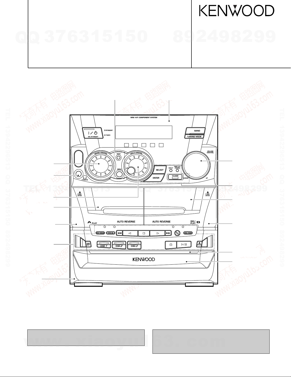
Knob
(K29-7541-02)
TEL 13942296513 QQ 376315150 892498299
Knob
(K29-7545-04)
Phone jack
(E11-0280-05)
TEL
Knob
(K29-7544-04)
Front glass
(B10-3448-02)
13942296513
Q
Q
3
7
Front glass
(B10-)
3
6
1
© 1999-1/B51-5500-00 (K/K) 3590
Knob
(K29-7543-04)
Knob
(K29-7541-02)
4
2
9
8
0
5
1
5
Front glass
(B10-3449-02)
9
8
2
9
TEL 13942296513 QQ 376315150 892498299
9
Cassette lid (L)
(A53-2121-02)
Knob
(K29-7553-01)
Panel *
(A60-)
**Refer to page 2 if you want to know system configuration.
In compliance with Federal Regulations, following are reproductions of labels on, or inside the product relating to laser product
safety.
w
w
w
.
xia
o
y
u
1
Cassette lid (R)
(A53-2122-02)
Front glass
(B10-3471-03)
Panel (CD)
(A29-1046-02)
Illustration is RXD-402.
* Refer to parts list on page 48~.
KENWOOD-Crop. certifies this equipment conforms to DHHS
Regulations No. 21 DFR 1040. 10, Chapter 1, Subchapter J.
6
3
.
c
o
DANGER : Laser radiation when open and interlock defeated.
AVOID DIRECT EXPOSURE TO BEAM
m
SYSTEM MAIN UNIT SPEAKER DESTINATION SYSTEM MAIN UNIT SPEAKER DESTINATION
XD-402 RXD-402 LS-N402 KPET XD-502 RXD-502 LS-N502 KPE
XD-402E RXD-402E LS-N402 E1 XD-502E RXD-502E LS-N502 E1
XD-402W RXD-402W LS-N402 Q XD-502W RXD-502W LS-N502 Q
XD-452 RXD-452 LS-N452 MXYTE XD-552 RXD-552 LS-N552 MXYTE
XD-452E RXD-452E LS-N452 E1 XD-552E RXD-552E LS-N552 E1
XD-452W RXD-452W LS-N452 Q
XD-552W RXD-552W LS-N552 Q
XD-572S RXD-572S LS-N552 M1
XD-A41 RXD-A41 LS-N452 KP
XD-A51 RXD-A51 LS-N552 KP
VOLUME
CD
TAPE
MUTE
RC-552
REMOTE CONTROL UNIT
EX.BASS
TIME
INPUT
BAND
POWER
TAPE
A/B
RANDOM
REPEAT TEXT DISP.
TUNING
6
1 2 3
4 5 6
7 8 9
0 +10
32¡1
4
7
M
U
L
T
I
C
O
N
T
R
O
L
¢
DISC SKIP
SOUND
CONTROL
MENUBACK
SELECT
ENTER
VOLUME
CD
TAPE
MUTE
MENU
RC-552E
REMOTE CONTROL UNIT
EX.BASS
TIME
INPUT
BAND
PTY
TA/NEWS RDS DISP.
POWER
BACK
TAPE
A/B
RANDOM
REPEAT TEXT DISP.
TUNING
6
SET
ENTER
1 2 3
4 5 6
7 8 9
0 +10
32¡1
4
7
M
U
L
T
I
C
O
N
T
R
O
L
¢
DISC SKIP
SOUND
CONTROL
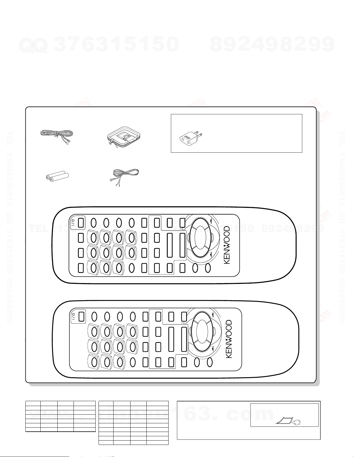
FM indoor antenna
(1)
AM loop antenna
(1)
Speaker cords (2)
Remote control
(A70-1262-05): TEQE1...RC-552E
(A70-1253-05): KPMXYM1...RC-552
unit
(1)
Remote control unit
(1)
Use to adapt the plug on the power cord to
the shape of the wall outlet.
(Accessory only for regions where use is
necesary.)
AC plug adaptor (1)
Provided in the speaker package
Batteries
(T90-0836-05) (T90-0837-05)
(E30-5535-05)
(E03-0115-05)
(R6/AA)
(2)
RXD-402/452/502/552/572S/A41/A51
Unplug the power cord from the power outlet
then, while holding the ENTER key depressed,
plug the power cord again.
÷
Please note that resetting the microcomputer clears
the contents stored in and returns and to condition
when it left the factory.
Operation to reset
The microcomputer may fall into malfunction (impossibility to operate, erroneous display, etc.) when the
power cord is unplugged while power is ON or due to
an external factor. In this case, execute the following
procedure to reset the microcomputer and return it to
normal condition.
(Main unit only)
CONTENTS / ACCESSORIES / CAUTIONS
Contents
Q
Q
CONTENTS/ACCESSORIES/CAUTIONS...................2
EXTERNAL VIEW/DISASSEMBLY FOR REPAIR.......3
BLOCK DIAGRAM.......................................................4
CIRCUIT DESCRIPTION.............................................5
ADJUSTMENT.......................................................... 10
WIRING DIAGRAM....................................................14
Accessories
3
7
6
3
1
5
1
5
0
PC BOARD ................................................................15
SCHEMATIC DIAGRAM............................................23
EXPLODED VIEW .....................................................44
PARTS LIST...............................................................48
SPECIFICATIONS.....................................................59
TEL 13942296513 QQ 376315150 892498299
8
9
2
4
9
8
2
9
9
TEL 13942296513 QQ 376315150 892498299
TEL
System configuration
w
2
13942296513
w
w
.
xia
o
y
u
Q
Q
Cautions
1
6
7
3
3
5
1
3
6
.
c
1
0
5
o
9
8
m
2
4
ENTER
9
8
2
9
9
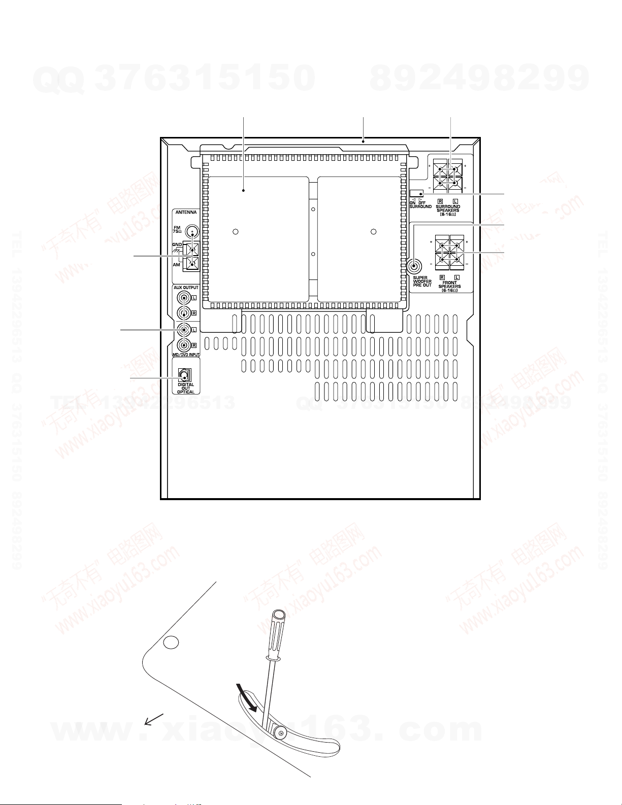
RXD-402/452/502/552/572S/A41/A51
BOTTOM SIDE
FRONT
HOW to open the tray if not comes out.
(1) Turn the friction arm counterclockwise
using a screw driver and the like.
(2) Pull out the tray front wards by hand
when the tray comes just out.
EXTERNAL VIEW / DISASSEMBLY FOR REPAIR
7
EXTERNAL VIEW
Q
Q
TEL 13942296513 QQ 376315150 892498299
Lock terminal board
(E20-0321-05)
Phono jack
(E63-1037-05)
Oscillating module
(W02-1114-05)
3
6
3
1
5
1
Cover
(F07-1655-02)
5
0
Metallic cabinet
(A01-3681-01)
8
9
4
2
Lock terminal board
(E70-0053-05)
9
2
8
Slide switch
(S62-0077-05)
Phono jack
(E63-0116-05)
Lock terminal board
(E70-0053-05)
9
9
TEL 13942296513 QQ 376315150 892498299
TEL
DISASSEMBLY FOR REPAIR
13942296513
5
1
5
1
3
6
7
3
Q
Q
8
9
4
2
9
8
0
Illustration is RXD-402.
2
9
9
w
w
w
.
xia
o
y
u
1
6
3
.
c
o
m
3
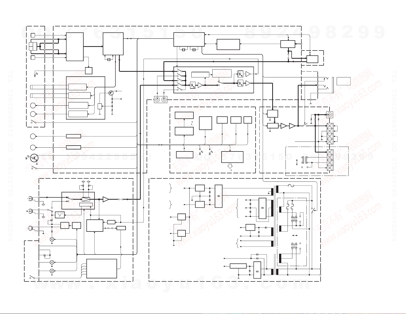
A PB
B R/P
B ERASE
BIAS
OSC CTRL
BIAS
VR5
HA12219NT
IC1
HA12136A
IC2
MPX
DPSS
IC4
HD74HC166P
FL DISPLAY
ED1
M66004SP
IC51
DRIVER
REMOCON
A1
D52
TIMER
D51
STANDBY
KEY
MATRIX
ENHANCED IC
FOR LED
IC52,53
JOG A JOG B VOL.
BU2090
+12V
AVR
Q4
AVR
Q6,7
-12V
-12V
+12V
AVR
IC2
+5V
AVR
IC1
+9V
RDS
CD +9V
-B
GND
+B
+40V
AVR
Q8
(X14- ) +5V
FL -35V
Q2
+5.6V AVR
u-COM
FAST OFF
FL AC
AMP
for
POWER
AC IN
RF AMP
CXA1571M
IC5
E-VOL
TUNER
DECK
TUNER
E-VOL
FL IC +5V
u-COM
PULL UP
DRIVER
TRACKING COIL
4ch BTL DRIVER
BA5979S
DRIVER
FOCUS COIL
DRIVER
FEED MOTOR
DRIVER
DISC MOTOR
IC6
A
B
C
E
F
SW
LD
Q501
DSP.SERVO.
CXD2587Q
IC7
DAC
CD +5V
CD +9V
(DSP,RF)
Q505
FM
DM
TA8409S
(ROTARY TRAY)
TA8409S
(LOADING)
LM
RM
IC8
IC9
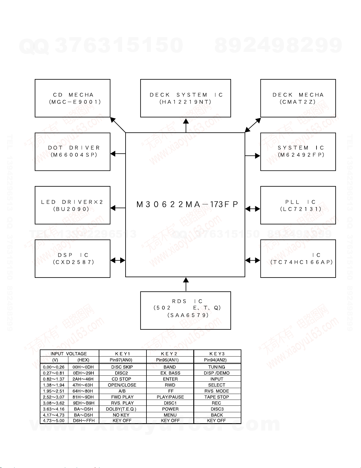
M30622MA-173FP
u-COM IC
IC1
IC2
K1
120V 240V
INPUT
OUTPUT
MD/DVD
MD REC
J1
SURROUND
3BAND TONE
EX-BASS
M62492FP
SELECTOR,SURROUND,TON,E-VOL
RDS
DEMODULATOR
IC3 (T,E,Q TYPE ONLY)
SAA6579T/R
MODULE
TUNER
ANT.
PHONES
HEAD
POLAR
UNIT
-10dB
ATT
AMUTE
S1
OFF
ON
ON/OFF
MATRIX
K1
RELAY
SPEAKER
ch.
OTHER
OUT
SW
Lch
Rch
SPEAKER
MATRIX
SPEAKER
BCLASS
ACLASS
Q1,2
Q3,4
B
A
REQ EQ
BIAS TRAP
PH A,B
MOTOR A
MOTOR B
MOTOR
SOL A,B
SPEED
TAPE
A/B
MOTOR
SOL A,B
VR7,8
LEVEL
B PB
LEVEL
VR1,2
A PB
PH A,B
B.CANCEL
BIAS
NOR
A-N/C
A/B
B1/2
DOLBY
R/P
DPSS
A,B CrCO2
L REC
R REC
A,B PACK
A,B PLAY
PSIN
CLK
PSLOAD
GRID
SEG1635
CLK
CS
DATA
KEY3
KEY2
KEY1
DATA1/2
CLK
15LED
A JOG
1/2 1/2
B JOG
1/2
ENC
+
+
+
+
+
+
RF.FE.TE
16.93MHZ
LOM+/-
ROM+/-
PHTR
TD/TU
CL/OP
PSW
MAIN
10MHz
SUB
32.768kHz
DATA
CLK MPX
TAPE REC
CLK
LATch
DATA
MECHA.
DECK
(X28- )
(X14- )
(X00- )
(X14- )
(X04- )
(X13- )MGC-E9001
CD MECHA.
Q TYPE ONLY
2-71
0-22
X07-3030-21
ONLY
M TYPE ONLY
RXD-402/502
(X07- )
4
RXD-402/452/502/552/572S/A41/A51
7
6
13942
w
.
3
29651
x
Q
Q
3
TEL 13942296513 QQ 376315150 892498299
TEL
w
w
i
1
a
5
3
o
1
y
5
u
0
Q
Q
1
6
5
4
0
m
9
9
8
8
2
5
1
2
o
3
1
9
c
8
6
7
3
3
.
9
4
2
2
8
9
9
9
TEL 13942296513 QQ 376315150 892498299
BLOCK DIAGRAM
9
RXD-402/452/502/552/572S/A41/A51
CIRCUIT DESCRIPTION
7
1. Initialization
Q
Q
1-1 Setting of initial conditions
1-2 Initializing operation
TEL 13942296513 QQ 376315150 892498299
1-3 Initial items and back up data
AMP S. DIRECT OFF
TUNER *FREQUENCY LOWEST FREQUENCY
TEL
CLOCK *PROG. RECORDING ON/OFF TIME
DECK *RVS MODE REVERSE
1-4 Mechanism initialization
1-4-1 CD mechanism
1-4-2 DECK mechanism
1-4-3 Error display
3
While pressing the [ENTER] key, put the plug into an AC
power outlet.
• A microcomputer is initialized for start when the AC
power is turned on when pressing the [ENTER] key. At
that time, CD mechanism and CASSETTE mechanism
are also initialized.
• During the initial operation,the display shows INITIALIZE
and after that it will be returned to STANDBY condition.
*POWER STANDBY
*VOLUME 14
*BALANCE CENTER
MUTING OFF
PROTECTION OFF
DISPLAY MODE AUTO
*AUTO POWER SAVE OFF
*MD/DVD INPUT LEVEL -3
*INPUT SEL. TUNER
*BAND FM
*AUTO/MONO AUTO
*P.CH --CH
*CLOCK 0:00 (E/T/Q) 12:00 (OTHERS)
13942296513
*PROG. TIMER PLAY ON/OFF TIME 0:00 (E/T/Q)
SLEEP TIMER OFF
O.T.T. OFF
*DIRECTION FORWARD
*A/B B
*BACKED UP DATA
• Disc unclamps(traverse down).
• Rotary tray rotates(1/3 rotation).
• If a mechanism error occurs, CD ERR is indicated on the
display.
• When initial condition becomes NG for the third time,
decide the error. The error condition is displayed as X
ERR on the display.
• If both mechanism (CD/DECK) error occur, the display is
indicated as follows. CD & X ERR
6
1
3
5
ITEMS
0:00 (E/T/Q) 12:00 (OTHERS)
12:00 (OTHERS)
1
5
0
Q
Q
2. Destination list of TUNER
Destinat-
ion
K,P K1
M,V,X,Y
AM 530k Hz~1610kHz 10k Hz +450k Hz 10kHz
M K3
M,V,X,Y
AM 531k Hz~1602kHz 9kHz +450kHz 9kHz
M E3
E
T
QQ
2-1 Discrimination of TUNER destination
Destina- R107 Voltage
tion [½] [V]
M1 39k 3.98
M2 22k 3.44
7
3
Q 4.7k 1.60
3. Test mode
3-1 Test mode of the receiver
3-1-1 Setting of the test mode
While pressing the [INPUT] key or [BAND] key, put the
plug into an AC power outlet.
3-1-2 Canceling of the test mode
Unplug an AC power cord from an AC power outlet.
3-1-3 Condition in test mode
• Power • • • • ON
• EX.BASS • • • OFF
• S.W • • • • • • • OFF
• Selector mode or FL indication
KEY
[BAND] TUNER • STANDBY and TIMER LEDs blink up.
+ AC ON • The all illminated state is cleared by
[INPUT] AUX • AUX TEST
+ AC ON
4
2
9
8
Tuner
BAND
type
FM 87.5MHz~108.0MHz 100k Hz +10.7MHz 25kHz
AM 530kHz~1700kHz 10kHz +450kHz 10kHz
K2 FM 87.5MHz~108.0MHz 100k Hz +10.7MHz 25kH
FM 87.5MHz~108.0MHz 100k Hz +10.7MHz 25kHz
MW 530kHz~1610kHz 10k Hz +450k Hz 10kHz
SW 5.9MHz~17.9MHz 5kHz +450k Hz 5kHz
E1 FM 87.5MHz~108.0MHz 50k Hz +10.7MHz 25kHz
FM 87.5MHz~108.0MHz 50kHz +10.7MHz 25kHz
MW 531kHz~1602kHz 9kHz +450k Hz 9kHz
SW 5.9MHz~17.9MHz 5kHz +450k Hz 5kHz
E1 FM 87.5MHz ~108.0MHz 50k Hz +10.7MHz 25kHz
RDS AM 531kHz~1602kHz 9kHz +450kHz 9kHz
FM 87.5MHz ~108.0MHz 50kHz +10.7MHz 25kHz
E2
MW 531kHz~1602kHz 9kHz +450k Hz 9kHz
RDS
LW 153kHz~279k Hz 9kHz +450kHz 9kHz
FM L 65.0 MHz~74.0 MHz 10kHz +10.7 MHz 5kHz
FMH 87.5MHz~108.0MHz 50kHz +10.7MHz 5kHz
MW 531kHz~1602kHz 9kHz +450k Hz 9kHz
LW 153kHz~279kHz 9kHz +450kHz 9kHz
K 91k 4.51
1
3
6
T 13k 2.83
E 8.2k 2.25
SELECTOR
MODE
Receiving
frequency range
0
5
1
5
• All the fluorescent display indicators
and LEDs light on.
pressing any main unit keys or
remocon keys.
9
Channel
space
2
9
8
FL INDICATION
8
AVdd
10
k½
4
R107
2
IF RF
8
9
9
X13
IC1
91pin
(TYPE)
2
9
9
TEL 13942296513 QQ 376315150 892498299
9
w
w
w
.
xia
o
y
u
1
6
3
.
c
o
m
5
RXD-402/452/502/552/572S/A41/A51
CIRCUIT DESCRIPTION
3-1-4 Basic operation in test mode
Q
Q
(1) The muting during mode selection is not controlled in
the test mode.
(2) The test mode is cancelled when the AC power is
turned off.
(3) The operation of the keys in the test mode as follows.
3-1-5 The operation of the keys in the test mode
(1) DISPLAY /DEMO key
When this key is pressed in the test mode, all the fluorescent display indicators and leds light off and normal display are indicated cyclically.
TEL 13942296513 QQ 376315150 892498299
(2) REV.MODE,DOLBY NR,A/B,REC/ARM keys
The volume level settings can be made as follows.
REV.MODE • • • volume min+1step
DOLBY • • • • • • volume 14 *RXD-402(TAPE E.Q.)
A/B • • • • • • • • • volume20
REC/ARM • • • • volume max (50)
(3) DISC SKIP key
With the selector on TUNER, the S level indication
changes cyclically as follows by pressing the [DISC
SKIP] key.
1 ATT is switched off. "ATT off & TUNER S level
XX"
2 ATT is switched on. "ATT on & TUNER S level
XX"
3 ATT is switched off. Normal display.
TEL
w
6
XX means A/D value(HEX) of S.
(4) DECK STOP key
With the selector on TUNER, when the [DECK STOP]
key operated, the preset memory can be changed as
10 steps.
(5) FWD PLAY/RVS key
With the selector on TUNER, the P. CALL is operated
by pressing the [ FWD PLAY] and [ RVS PLAY] keys.
FWD PLAY key • • • • P. CALL up
RVS PLAY key • • • • P. CALL down
(6) CD OPEN /CLOSE key
With the selector on TUNER, the channel space settings can be made cyclically by pressing the [CD
OPEN/CLOSE] key with M version.
(7) DECK STOP key
With the selector on AUX, when the [DECK STOP ]
key operated,the S. direct (ON/OFF) can be changed.
(8) DISC 1 key
With the selector on something other than TUNER,
whenever the [DISC1] key is pressed, the setting of
E.Q changes cyclically as follows.
(9) DISC 2 key
With the selector on AUX, MD/DVD input level can be
made cyclically by pressing the [DISC 2] key .
w
3
7
6
3
1
5
1
13942296513
10 20 30 40 00( )
E.Q MAX E.Q MIN E.Q FLAT
w
INITIALIZED VALUE íî LEVEL MAX
.
xia
o
y
5
u
0
Q
1
(10) DISC 3 key
With the selector on AUX, the balance level setting
can be made cyclically by pressing the [DISC 3] key .
(11) DISC SKIP key
With the selector on something other than TUNER,
the muting (ON/OFF) can be changed.
3-2 Test mode of cassette deck
3-2-1 Setting of the test mode
While pressing the [deck play] key, put the plug into an
AC power outlet.
3-2-2 Canceling of the test mode
Unplug an AC power cord from an AC power outlet.
3-2-3 Condition in test mode
(1) Initial condition
• DOLBY-0FF
• AUDIO-MUTE OFF
(2) Mechanism SW detection
A pack SW E.Q
A -CRO2 PROG.12
B-FWD O.T.T
B pack SW AUTO
B-CRO2 ST
B-RVS ANTENNA
7
3
Q
(3) 4-sec recording
If the REC key is pressed, the system record for 4
sec. Then, it rewinds to the recording starting position
and plays back automatically.
If the REC key is pressed, during the 4-sec recording
operation, the system records further for 4-sec, then
return to the starting position of the first 4-sec recording operation and plays back.
3-3 Test mode of CD player
3-3-1 Setting of the test mode
While the pressing the [PLAY/PAUSE] key, put the plug
into an AC power outlet.
3-3-2 Canceling the test mode
Press the stop key on stop mode or unplug the AC cord
from an AC power outlet.
3-3-3 The operation of the keys in the test mode.
PLAY/PAUSE
PLAY/PAUSE
6
3
4
2
9
8
Lch MAX Rch MAX CENTER
DISPLAY
8
0
5
1
5
1
3
6
KEY DISPLAY OPERATION
• Setting of the test mode.
• Tray 1/3 rotation.
• Tray opens automatically.
• Tray closes.
• Change or cancel the test mode.
• Tray closes/disc clamps.
• T-servo off(03) or on (05).
• Mechanism stops when the
automatic adjustment is finished.
• Display changes cyclically.
• If NG, display blinks up.
• Tray closes.
o
m
• Disc2 clamps.
• Plays track 16.
• Tray closes/disc clamps.
• Plays track 32.
.
CD TEST
03 --:-05**:**
07 EF/FB
08 TG/FG
09 TE/RF
10 TE/VC
c
+AC IN
STOP 0
DOWN FINISH • Tray 1/3 rotation.
DISC3
DISC2 216**:**
DISC1
9
9
8
2
4
2
9
8
9
2
9
9
TEL 13942296513 QQ 376315150 892498299
9
RXD-402/452/502/552/572S/A41/A51
SERIES
EXPANDER
X14, IC51
X14, IC52, 53
X04, IC7
X04, IC3
TUNER PACK IC2
X28, IC4
X04, IC2
X28, IC1
X13, IC1
CIRCUIT DESCRIPTION
7
4. Main microprocessor
Q
Q
4-1 Microprocessor periphery block diagram
TEL 13942296513 QQ 376315150 892498299
3
6
3
1
5
1
5
0
8
9
2
4
9
8
2
9
9
TEL 13942296513 QQ 376315150 892498299
TEL
13942296513
4-2 Key matrix
Q
Q
3
7
5
1
3
6
0
5
1
8
9
2
4
9
8
2
9
9
w
w
w
.
xia
o
y
u
1
6
3
.
c
o
m
7
RXD-402/452/502/552/572S/A41/A51
CIRCUIT DESCRIPTION
4-3 Pin description of microprocessor: M30622MA-173FP (X13, IC1)
Q
Q
Pin No. Name I/O Description Active
1 S.LEVEL I RDS S level input.
2 PLL DO I PLL IC data input.
3 SD I SD detector input.
4 ST I Stereo detector input.
5 PLL CE O PLL IC chip enable.
6 RDS DATA I RDS data input.
7 PLL CLK O PLL IC clock output.
8 BYTE I Ground.
9 CNVSS - Ground.
TEL 13942296513 QQ 376315150 892498299
10 XCIN I Timer clock input(32.768kHz).
11 XCOUT O Timer clock output(32.768kHz).
12 RST I u-com reset signal input. H : normal L : reset
13 XOUT O Main clock output(10MHz).
14 VSS - Ground.
15 XIN I Main clock input(10MHz).
16 VCC(BU) - No used (+5v).
17 HMI - u-com power supply(+5v).
18 REM I Remocon signal input. H : normal L : reset
19 RDS CLK I RDS clock input.
20 SCOR I Sub code synchronism signal input.
21 NC - No connection.
22 CLSW I CD load switch (SW3) input port of CD mechanism.
23 OPEN SW I CD unload switch (SW3) input port of CD mechanism.
24 RTL O Rotary motor opposite direction (CCW) output.
25 BRKM O Rotary motor brake control. H : normal L brake
TEL
26 CLOSE O Load motor opposite direction (taking out) output.
27 OPEN O Load motor positive direction (dragging out) output.
28 SQCK O CD sub code clock output.
29 SQSO I CD sub code input.
30 NC - No connection.
31 FL DATA O FL driver data output.
32 CE I Power failure signal input. H : AC on L : AC off
33 FLCLK O FL driver clock output.
34 FLCS O FL driver strobe output.
35 RTR O Rotary motor positive direction (CW) output.
36 TDSW I Traverse down switch (SW1) input port of CD mechanism. H : off L : on
37 TUSW I Traverse up switch (SW1) input port of CD mechanism. H : off L : on
38 PHTR I CD photo transistor (Q1) detector input.
39 PSSW I
40 XRST O CD DSP IC reset control.
41 CD MUTE - No connection.
42 DC OFF O CD DSP IC power control. H : on L : off
43 MON O Spindle motor (ON/0FF) changeover. H : on L : off
44 LDC O Laser ON/OFF signal output. H : off L : on
45 SCLK O CD sense data read out clock output.
46 SENS I CD sense input.
47 CLOK O CD DSP IC clock.
48 XLAT O CD DSP IC latch.
49 DATA O Data output to DSP IC.
50 EVCLK O Clock output to E. vol(IC2).
51 EVLAT O Latch output to E. vol(IC2).
w
w
52 EVDATA O Data output to E. vol(IC2).
53 A-JOG1 I Jog A (S28) input.
8
7
3
13942296513
w
6
.
xia
1
5
1
y
5
u
0
Q
Q
1
3
6
7
3
3
Tray position & disc detector switch (SW2) input port of
CD mechanism.
o
6
8
3
.
9
1
1
5
c
2
5
o
4
0
m
9
8
9
8
2
4
2
9
8
9
2
9
9
TEL 13942296513 QQ 376315150 892498299
9
RXD-402/452/502/552/572S/A41/A51
CIRCUIT DESCRIPTION
Q
TEL 13942296513 QQ 376315150 892498299
Pin No. Name I/O Description Active
Q
54 A-JOG2 I Jog A (S28) input.
55 B-JOG1 I Jog B (S29) input.
56 B-JOG2 I Jog B (S29) input.
57,58 ENC1,2 I Rotary encoder(S27) input.
59 LEDCLK O Clock output to LED controller(IC52,53).
60,61 LEDDT1,2 O Data output to LED controller(IC52,53).
62 VCC(BU) - u-com power supply(+5v).
63 LMUTE O Deck line mute control.
64 VSS - Ground.
65 B-PH I B deck reel sensor input.
66 A-B2 O Deck A/B changeover control 1.
67 A-B1 O Deck A/B changeover control 2.
68 A120/70 O Play back equalizer control. H :70u L :120u
69 B1/2 O Muting control for recording.
70 D-R/P O Dolby recording/play back control. H : recording L : playback
71 DOLBY O Dolby B ON/OFF changeover. H : on L : off
72 R/P O Deck recording /play back control. H : recording L : playback
73 NOR O NORMAL/CRO2 changeover.
74 BIAS O Deck bias control output. H : on L : off
75 BEAT.C O Deck beat cancel control output. H : on L : off
76 B.SOL O Deck solenoid control output. H : on L : off
77 CPM O Deck motor control output. H : on L : off
78 A.SOL 0 Deck solenoid control output. H : on L : off
79 CLK O Clock output to bias control IC(X28,IC4).
80 PSLOAD O Parallel serial IC load. H : shift L : load
81 AMUTE 0 Audio muting control. H : off L : on
TEL
82 ATT O E. volume attenuation output. H : off L : on
83 POWER O Power relay control. H : on L : off
84 PROTECT I Protection detection input. H : protection on L : off
85 SP.RELAY O Speaker relay control output. H : on L : off
86 LED(STBY) O LED(STANDBY) control output. H : on L : off
87 LED(TIMER) O LED(TIMER) control output. H : on L : off
88 PSIN I Parallel serial IC input data.
89 SPEANA I Music signal input port.
90 MODEL I Model discrimination input. H :XD-502 L :XD-402
91 TYPE I Discrimination port of tuner destination.
92 DPSS I Deck DPSS detection input.
93 A-PH I A deck reel sensor input.
94,95 KEY3,2 I A/D key input (key3,2).
96 AVSS - A/D ground.
97 KEY1 I A/D key input (key1).
98 VREF - A/D reference voltage.
99 AVCC(BU) - Analog power supply(+5V).
100 PLL DATA I PLL IC data input.
7
3
13942296513
6
3
1
5
1
5
0
Q
Q
3
7
6
8
3
9
1
5
1
2
5
4
0
9
8
9
8
2
4
2
9
8
9
2
9
9
TEL 13942296513 QQ 376315150 892498299
9
5. IC controller
5-1 RDS LED driver
Pin No. Name I/O Description
1 VSS - GND
2 DATA I DATA INPUT
3 CLOCK I CLOCK INPUT
4 PTY O PTY ON/OFF LED
w
w
w
5 NC O NO USED
6 EON O EON INT LED
7 NC O NO USED
.
xia
o
y
u
1
Pin No. Name I/O Description
8 TA O TA ON/OFF LED
9 TP O TP ON/OFF LED
10 RDS O RDS ON/OFF LED
11~13 NC O NO USED
6
3
.
c
o
14 NEWS O NEWS ON/OFF LED
15 NC O NO USED
16 VDD - +5V POWER SUPPLY
m
9

RXD-402/452/502/552/572S/A41/A51
No.
ITEM
INPUT
SETTINGS
OUTPUT
SETTINGS
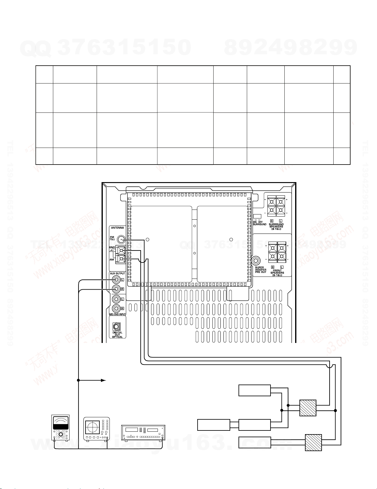
AMPLIFIER
SETTINGS
ALIGNMENT
POINTS
ALIGN FOR
FIG.
Unless otherwise specified, the individual switches should be set as following :
POWER : ON SELECTOR : CD
1
IDLE CURRENT
–
Connect a DC
voltmeter to
CN3 (Lch),
CN4 (Rch)
X07, A/2.
VOLUME : 0
VR1 (L)
VR2 (R)
X07, A/2
6 mV
(a)
Dc voltmeter
6 mV
CN3 (L)
CN4 (R)
(a)
ADJUSTMENT
7
Amp adjustment
Q
Q
TEL 13942296513 QQ 376315150 892498299
3
6
3
1
5
1
5
0
8
9
2
4
9
8
2
9
9
TEL 13942296513 QQ 376315150 892498299
TEL
13942296513
Q
Q
3
7
6
3
1
5
1
5
0
8
9
2
4
9
8
2
9
9
w
w
w
10
.
xia
o
y
u
1
6
3
.
c
o
m
RXD-402/452/502/552/572S/A41/A51
X04-1313 Q TYPE (65MHz~74MHz BAND)
N0.
ITEM
INPUT
SETTINGS
OUTPUT
SETTINGS
TUNER
SETTINGS
ALIGNMENT
POINTS
ALIGN FOR
FIG.
1
VCO
(C)
69 MHz,
70 dBf (ANT INPUT)
1 kHz, 0 kHz DEV
SUB, 0 kHz DEV
Connect a frequency
counter to VCO monitor
X04 (CN2).
AUTO
69 MHz
VR 2
Adjust it the
frequency counter
reads 31.25 kHz
±100 Hz.
(a)
2
RESONANCE
POINT
(C)
69 MHz,
70 dBf (ANT INPUT)
1 kHz, 40 kHz DEV
SUB, 10 kHz DEV
Select : L or R
Connect a oscilloscope
to TUNER OUT(CN6).
AUTO
69 MHz
TC 1
Minimum
crosstalk.
(a)
3
SEPARATION
(C)
SAME AS ABOVE
Connect a oscilloscope
to TUNER OUT(CN6).
AUTO
69 MHz
VR 1
Minimum
crosstalk.
(a)
(A)
(B)
(C)
(D)
AM-SG
FM-MPX-SG
FM-MPX-SG
TO CN6
3pin (Lch)
1pin (Rch)
2pin (GND)
POLAR SG
AC voltmeter
Oscilloscope
Distortion meter
Dummy antenna
Fig (a)
ADJUSTMENT
7
Tuner adjustment
Q
Q
TEL 13942296513 QQ 376315150 892498299
3
6
3
1
5
1
5
0
8
9
2
4
9
8
2
9
9
TEL 13942296513 QQ 376315150 892498299
TEL
13942296513
Q
Q
3
7
6
3
1
5
1
5
0
8
9
2
4
9
8
2
9
9
w
w
w
.
xia
o
y
u
1
6
3
.
c
o
m
11
X13 FOIL SIDE VIEW
VR1
FE. B
RF FE1 FE2 TE2 TE1 VC
RXD-402/452/502/552/572S/A41/A51
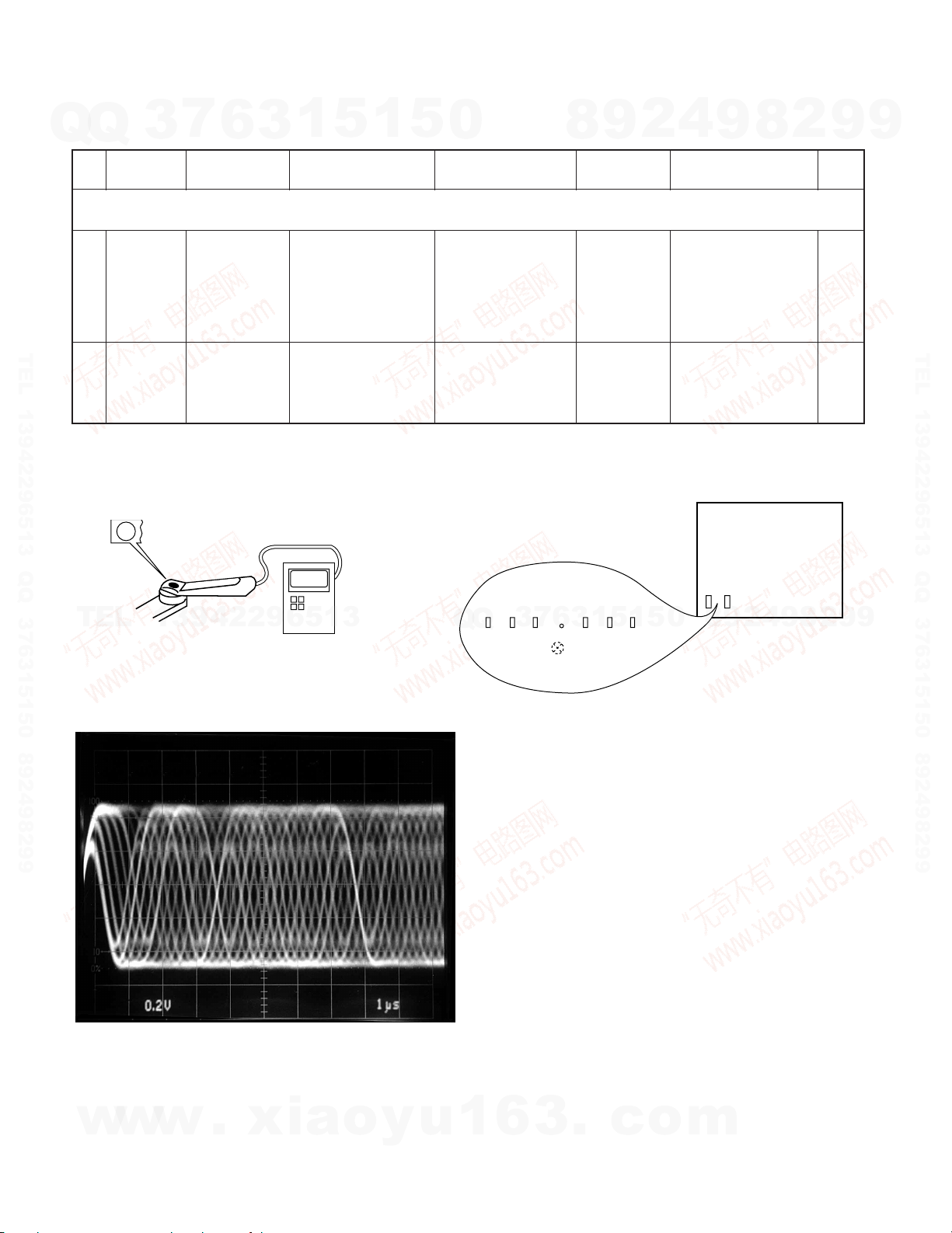
ADJUSTMENT
7
Q
Q
CD player adjustment
No.
Step 1,2 are in TEST MODE
TEST MODE : While pressing the [CD PALY] key, plug the AC power cord into the AC power wall outlet.
1
TEL 13942296513 QQ 376315150 892498299
2
Note:
Type 4disc :SONY YEDS-18 Test Disc or equivalent. (KTD-02)
LPF : Around 47k½ + 390pF or so.
(a) Laser Power (b) Test point
3
ITEM
LASER
POWER
FOCUS
ERROR
BIAS
6
INPUT
SETTING
–
Test disc
Type 4
1
3
0.05~0.15 mW
5
OUTPUT
SETTING
Set the senor section
of the optical power
meter on the pickup
Connect an oscillo-
scope as follows.
CH1 : RF
CH2 : FE1
GND : VC
lens.
1
5
0
PLAYER
SETTING
Press the"PLAY"key
to check that the dis-
play is "03".
Press the "PLAY"
key. Confirm that the
display is”05”
9
8
ALIGNMENT
POINT
FE
BIAS VR1
–
4
2
9
ALIGN FOR
On the power
from.0.05 to 0.15mw.
when the diffraction
grating is correctly
aligned with the RF
level of 0.8Vp-p or
Optimum eye pattern
(DC=±330mV)
more
8
2
9
FIG.
(a)
(b)
(d)
9
TEL 13942296513 QQ 376315150 892498299
TEL
(d)
RF signal in test mode (PLAY).
Perform the tangential and focusing offset are focused
into one point on the display. The crossing points above
and below the center shall also be looked clearly.
13942296513
Pickup
RF signal FAC coupled
Optical power meter
Q
Q
3
7
6
3
1
5
1
5
0
8
9
2
4
9
8
2
9
9
w
w
12
w
.
xia
o
y
u
1
6
3
.
c
o
m
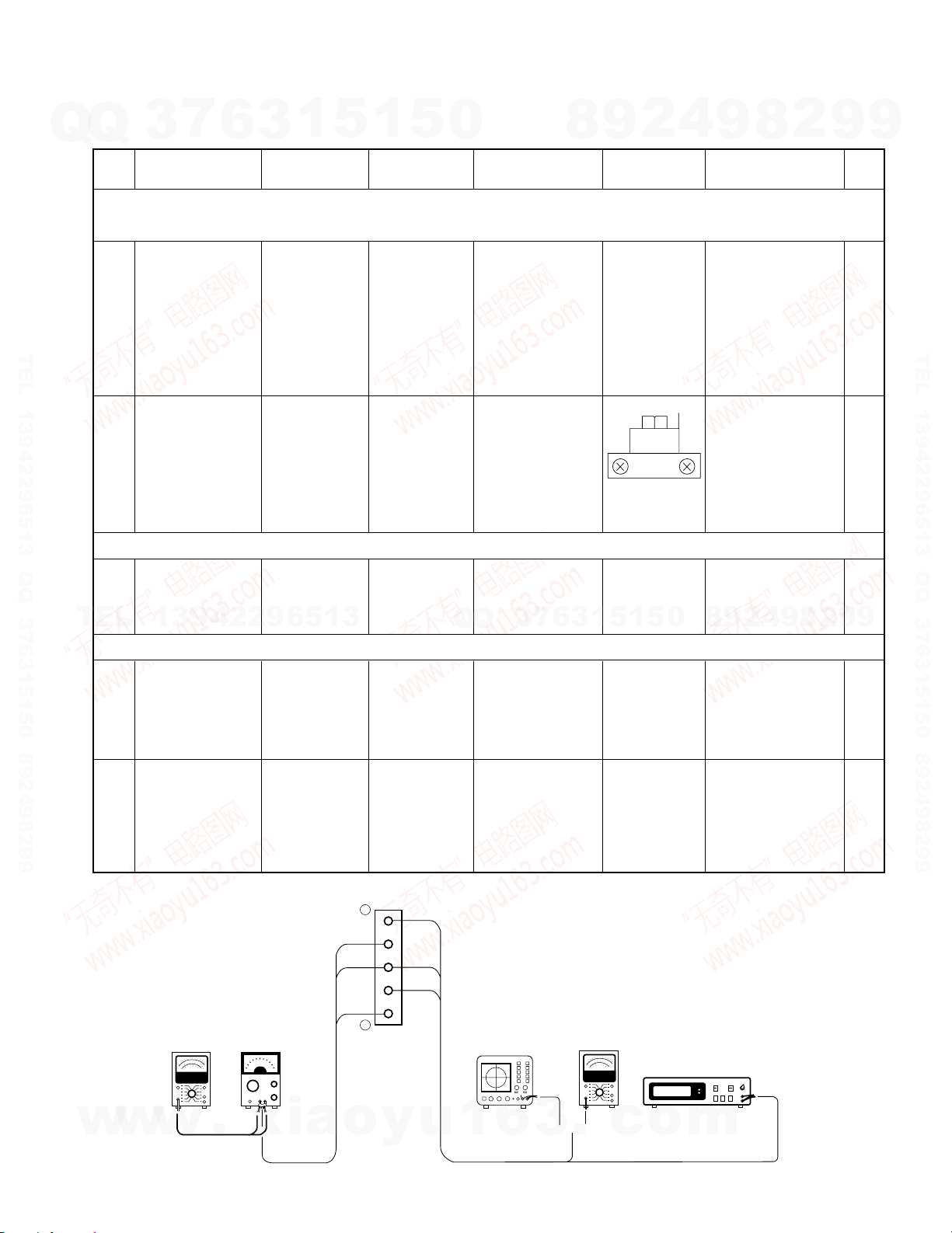
RXD-402/452/502/552/572S/A41/A51
{
(A) (B)
X28, CN6
L IN
L OUT
R OUT
R IN
GND
1
5
AC voltmeter AG
Oscilloscope
AC voltmeter
Frequency counter
ADJUSTMENT
7
Q
Q
Cassette Deck adjustment
TEL 13942296513 QQ 376315150 892498299
TEL
3
No
Unless otherwise specified, set the respective switches as follows: 0dBs=0.775V
TAPE : NORMAL DOLBY : OFF PLAY OUT : Lch (X28,CN6 @pin), Rch (X28,CN6 Cpin)
ø. Cassette mechanism unit (Adjustment of the REC / PLAY head)
Demagnetization
q1 r
q2 r
¿. PC BOARD ADJUSTMENT
q1 r
¡. PC BOARD ADJUSTMENT
and cleaning
Azimuth of the
REC/PLAY head
SPEED(NORMAL)
13942296513
6
ITEM
TAPE
1
3
INPUT
SETTING
\
TCC-153
MTT-114
10kHz, - 10dB
TCC-110
MTT-111
SCC-1727
3kHz
5
1
OUTPUT
SETTING
5
\
iB j
iB j
0
SETTING
Demagnetization:
POWER OFF
Cleaning: PLAY
Q
Q
DECK
PLAY
PLAY
7
3
6
8
3
2
9
ALIGNMENT
POINT
Recording
head, erase
head,capstan
pinch roller
FWD RVS
A/B DECK
1
5
1
VR 5
5
4
9
ALIGN FOR
Demagnetize the
REC / PLAY head
with the head eras-
er.Clean the REC /
PLAY head, erase
head,capstan and
pinch roller using a
cotton swab slightly
damped with alcohol.
Adjust the output to
maximum and adjust
the azimuth adjust-
ment screw for the
Lissajours waveform
pattern of the oscillo-
scope to become
close to a 45°
straight line.
Adjust the tape
speed so that 3kHz
is obtained at the
center of the tape.
2
9
8
0
8
4
2
9
8
9
2
9
9
FIG.
TEL 13942296513 QQ 376315150 892498299
9
q1 r
q2 r
w
w
PLAYBACK
BIAS CURRENT
w
LEVEL
.
xia
MTT-256U,
TCC-160
315Hz, 0dB
(A)
Adjust the AG
for the output of
the DECK to
become
1kHz(-30dBs)/
10kHz(-30dBs).
o
iB j
iB j
y
u
PLAY
Adjust the REC VR
level so that the line
out is -2.6dBs at
1kHz, and record
and playback
1kHz/10kHz alter-
nately.
1
6
3
A DECK
VR 1 (L)
VR 2 (R)
B DECK
VR 7 (L)
VR 8 (R)
VR 3 (L)
VR 4 (R)
.
c
o
Adjust the playback
output to -6.0dBs
Record 1kHz and
10kHz alternately,
and adjust the bias
current adjustment
potentiometer for the
playback levels to
become the same.
m
13
14
CN1
CN2
WH2
E2
CN1
CN1
WH3
E3
CN5
CN4
CN1
E1
WH1
E2
WH1
E1
J4
S1
SURROUND
SW
Rch
Lch
SURROUND
SPEAKERS
GND
J2
AM ANT
FM75
J1
MD REC OUTPUT
MD/DVD INPUT
A501
DIGITAL OUT
E1
WH3
E2
CN2 WH4
WH1
WH2
CN1
CN3 CN2
CN5
CN1
RXD-502E (X28-2980-10)
RXD-502W (X28-2983-81)
DESTINATION
RUSSIA
COUNTRY
Q
3-81
UNIT No.
ABB.
DESTINATION
EUROPE
COUNTRY
E1 0-10
UNIT No.
ABB.
ABB.COUNTRY
ABB.COUNTRY
EUROPE
U.S.A
CANADAEPK0-10
DESTINATION
RXD-502 (X28-2980-10)
RUSSIA
UNIT No.
Q
3-82
DESTINATION
RXD-402W (X28-2983-82)
EUROPE
UNIT No.
E1 0-11
DESTINATION
RXD-402E (X28-2980-11)
COUNTRY
U,K
UNIT No.
ABB.
T
RXD-452W (X28-2983-82)
RXD-572S (X28-2980-10)
RXD-552W (X28-2983-81)
RXD-402 (X28-2980-11)
DESTINATION
CANADA
U.S.A
EUROPE
COUNTRY
P
K
E
0-11
UNIT No.
ABB.
DESTINATION
RUSSIA
COUNTRY
Q
3-81
UNIT No.
ABB.
RXD-552E (X28-2980-10)
DESTINATION
EUROPE
COUNTRY
E1 0-10
UNIT No.
ABB.
DESTINATION
GENERAL MARKET
COUNTRY
M1 0-10
UNIT No.
ABB.
M
GENERAL MARKET
EUROPE
AUSTRALIA
U,K
E
T
X 0-10
DESTINATION
RXD-552 (X28-2980-10)
PX
COUNTRY
UNIT No.
Y
ABB.
RXD-A51 (X28-2980-10)
DESTINATION
U.S.A
CANADA
COUNTRY
K
P
0-10
UNIT No.
ABB.
DESTINATION
RUSSIA
COUNTRY
Q
3-82
UNIT No.
ABB.
RXD-A41 (X28-2980-11)
XAUSTRALIA
RXD-452E (X28-2980-11)
DESTINATION
EUROPE
COUNTRY
E1 0-11
UNIT No.
ABB.
JAPAN
EUROPE
U,K
J
E
T
0-11
GENERAL MARKET
DESTINATION
RXD-452 (X28-2980-11)
COUNTRYPXABB.
Y
M
UNIT No.
DESTINATION
U.S.A
CANADA
COUNTRY
K
P
0-11
UNIT No.
ABB.
RXD-502W (X13-7613-81)
ABB.
RUSSIA
COUNTRY
DESTINATION
3-81
Q
UNIT No.
E1
ABB.
EUROPE
DESTINATION
COUNTRY
2-71
UNIT No.
KU.S.A.
RXD-502E (X13-7612-71)
CANADA
EUROPEPE 2-71
0-10
ABB.
RXD-502 (X13-761X-XX)
COUNTRY
DESTINATION
UNIT No.
ABB.
RXD-402W (X13-7613-81)
DESTINATION
COUNTRY
RUSSIA
UNIT No.
3-81
Q
RXD-402E (X13-7612-71)
ABB.
E1
COUNTRY
EUROPE
DESTINATION
UNIT No.
2-71
U.K.
EUROPE
CANADA
U.S.A.
0-51T
2-71E
0-10
P
K
ABB.
RXD-402 (X13-761X-XX)
COUNTRY
DESTINATION
UNIT No.
ABB.COUNTRY
GENERAL MARKET M 0-21
RXD-572S (X13-7610-22)
ABB.
DESTINATION
COUNTRY
GENERAL MARKET M1
UNIT No.
0-22
ABB.
RXD-552W (X13-7613-81)
COUNTRY
RUSSIA
DESTINATION
UNIT No.
3-81
Q
RXD-552E (X13-7612-71)
E1
ABB.COUNTRY
EUROPE
DESTINATION
2-71
UNIT No.
EUROPE
AUSTRALIA
U.K.
E 2-71
X
T 0-51
DESTINATION
RXD-552 (X13-761X-XX)
ABB.COUNTRY
PX
DESTINATION
Y
UNIT No.
ABB.
CANADA
COUNTRY
U.S.A.
0-10
P
UNIT No.
K
UNIT No.
RXD-A51 (X13-7610-10)
ABB.COUNTRY
RUSSIA 3-81
Q
E1
RXD-452W (X13-7613-81)
DESTINATION
EUROPE 2-71
RXD-A41 (X13-7610-10)
0-01JJAPAN
RXD-452E (X13-7612-71)
DESTINATION
EUROPE
UNIT No.
2-71E
GENERAL MARKET
AUSTRALIA
U.K.
PX
0-21M
0-51T
X
Y
RXD-452 (X13-761X-XX)
ABB.
DESTINATION
COUNTRY
UNIT No.
ABB.COUNTRY
CANADA
U.S.A.
DESTINATION
P
K
0-10
UNIT No.
COUNTRY ABB.
COUNTRY ABB.
Q
ABB.
RXD-552W (X07-3030-21)
E1
RUSSIA
COUNTRY
DESTINATION
EUROPE
0-21
UNIT No.
0-21
RXD-552E (X07-3030-21)
Y
M
E
T
X
DESTINATION
EUROPE
AUSTRALIA
U.K.
GENERAL MARKET
PX
UNIT No.
0-21
RXD-552 (X07-3030-21)
P
K
ABB.
RXD-A51 (X07-3030-10)
DESTINATION
CANADA
U.S.A.
COUNTRY
DESTINATION
0-10
UNIT No.
UNIT No.
RXD-452W (X07-3030-11)
Q
ABB.
E1
RUSSIA
DESTINATION
COUNTRY
EUROPE
0-11
UNIT No.
0-11
ABB.
RXD-452E (X07-3030-11)
J
M
X
T
E
JAPAN
COUNTRY
DESTINATION
EUROPE
U.K.
AUSTRALIA
GENERAL MARKET
UNIT No.
0-22
0-11
ABB.
RXD-452 (X07-303X-XX)
Y
P
K
ABB.
DESTINATION
COUNTRY
PX
U.S.A.
CANADA
COUNTRY
DESTINATION
UNIT No.
0-11
UNIT No.
RXD-A41 (X07-3030-11)
COUNTRY ABB.
RXD-502W (X07-3030-21)
RUSSIA
DESTINATION
COUNTRY
0-21
Q
UNIT No.
ABB.
EUROPE
0-21
E1
DESTINATION
EEUROPE 0-21
RXD-502E (X07-3030-21)
DESTINATION
UNIT No.
CANADA
COUNTRY
U.S.A.
0-10
P
UNIT No.
K
ABB.
RXD-502 (X07-303X-XX)
RUSSIA 0-11
Q
RXD-402W (X07-3030-11)
DESTINATION
COUNTRY
UNIT No.
ABB.
RXD-402E (X07-3030-11)
COUNTRY
EUROPE
DESTINATION
ABB.
0-11E1
UNIT No.
EUROPE
U.K.
CANADA
E
0-11
T
P
RXD-402 (X07-3030-11)
DESTINATION
U.S.A.
COUNTRY
UNIT No.
K
ABB.
GENERAL MARKET
DESTINATION
COUNTRY
0-21
M1
UNIT No.
ABB.
RXD-572S (X07-3030-21)
RXD-552 (X00-293X-XX)
Y
M
ABB.
X
T
EEUROPE
AUSTRALIA
U.K.
COUNTRY
GEMERAL MARKET
PX
DESTINATION
2-71
0-21
UNIT No.
K
P
ABB.
RXD-A51 (X00-2930-10)
Q
CANADA
U.S.A.
COUNTRY
DESTINATION
RUSSIA
0-10
UNIT No.
2-72
UNIT No.
RXD-452E (X00-2932-72)
ABB.
RXD-452W (X00-2932-72)
ABB.
E1
DESTINATION
COUNTRY
COUNTRY
EUROPE
DESTINATION
UNIT No.
2-72
UNIT No.
J
E
T
X
Y
M
ABB.
JAPAN
EUROPE
GEMERAL MARKET
AUSTRALIA
U.K.
COUNTRY
PX
0-01
2-72
0-22
RXD-452 (X00-293X-XX)
RXD-A41 (X00-2930-11)
P
K
ABB.
DESTINATION
CANADA
DESTINATION
U.S.A.
COUNTRY
0-11
UNIT No.
COUNTRY ABB.
RUSSIA 2-72
Q
RXD-402W (X00-2932-72)
DESTINATION
UNIT No.
RXD-402E (X00-2932-72)
COUNTRY
EUROPE
DESTINATION
UNIT No.
2-72
ABB.
E1
UNIT No.
KU.S.A.
EUROPE
U.K.
CANADA
2-72
E
0-11
T
P
RXD-402 (X00-293X-XX)
DESTINATION
COUNTRY
UNIT No.
ABB.
RXD-572S (X00-2930-21)
GEMERAL MARKET
DESTINATION
COUNTRY
0-21M1
UNIT No.
ABB.
COUNTRY
RUSSIA 2-71
Q
ABB.
2-71E1EUROPE
RXD-552W (X00-2932-71)
DESTINATION
RXD-552E (X00-2932-71)
DESTINATION
COUNTRY
UNIT No.
ABB.
RXD-502E (X00-2932-71)
DESTINATION
RXD-502W (X00-2932-71)
DESTINATION
RUSSIA
COUNTRY
COUNTRY
EUROPE
Q
2-71
UNIT No.
ABB.
ABB.
E1 2-71
UNIT No.
RXD-502 (X00-293X-XX)
DESTINATION
EUROPE
CANADA
COUNTRY
U.S.A.
0-10
EP2-71
UNIT No.
K
ABB.
S2
S1
RXD-502 (X14-493X-XX)
RXD-502E (X14-4932-71)
RXD-502W (X14-4932-71)
RXD-402E (X14-4932-72)
E1EUROPE
Q
RUSSIA
DESTINATION
COUNTRY ABB.
DESTINATION
COUNTRY ABB.
EUROPE E
CANADA
COUNTRY
U.S.A
P
ABB.
K
DESTINATION
DESTINATION
COUNTRY
EUROPE
ABB.
E1
2-71
2-71
UNIT No.
UNIT No.
2-71
UNIT No.
0-10
2-72
UNIT No.
RXD-402W (X14-4932-72)
RXD-402 (X14-493X-XX)
RXD-552E (X14-4932-71)
RXD-A51 (X14-4930-10)
RXD-552 (X14-493X-XX)
RXD-552W (X14-4932-71)
RXD-572S (X14-4930-10)
DESTINATION
RUSSIA
COUNTRYQABB.
U,K
EUROPE
CANADA
T
E
P
DESTINATION
U.S.A
COUNTRYKABB.
E1EUROPE
DESTINATION
COUNTRY ABB.
Q
RUSSIA
DESTINATION
COUNTRY ABB.
GENERAL MARKET M1
GENERAL MARKET
EUROPE E
AUSTRALIA
U,K
X
T
M
DESTINATION
PX
COUNTRYYABB.
DESTINATION
COUNTRY ABB.
CANADA P
DESTINATION
U.S.A
COUNTRYKABB.
2-72
UNIT No.
0-11
2-72
UNIT No.
2-71
UNIT No.
2-71
UNIT No.
0-10
2-71
0-10
UNIT No.
0-10
UNIT No.
UNIT No.
RXD-452E (X14-4932-72)
RXD-452W (X14-4932-72)
RXD-A41 (X14-4930-11)
RXD-452 (X14-493X-XX)
Q
RUSSIA
DESTINATION
COUNTRY
EUROPE
ABB.
E1
DESTINATION
COUNTRY ABB.
EUROPE E
ABB.COUNTRY
GENERAL MARKET
AUSTRALIA
U,K
JAPAN
T
X
J
PX Y
M
DESTINATION
CANADA
U.S.APK
DESTINATION
COUNTRY ABB.
2-72
2-72
2-72
UNIT No.
UNIT No.
0-11
UNIT No.
0-11
UNIT No.
WH4
WH3
WH1
WH2
CN3
A
Rch 4
Lch 3
Rch 2
Lch 1
(OPTICAL)
J3
PRE OUT
S.W
Rch 2
Lch 1
J2
SPEAKERS
FRONT
A
NO
A
NO
A
NO
A
YES
A
YES
YES
A
A
NO
A
YES
YES
A
YES
YES
A
NO
A
NO
A
NO
A
YES
NO
A
NO
A
E1
33 33
1
1
12
1
12
1
11
11
1
1
21 21
1
1
112
112
1
4
1
4
ON
OFF
15 15
11
3
1
3
1
1
5
21
2
1
1
15
3
5
1
2
1
20120
1
1
33 33
1
F2
T1
220-240V
110-120V
1
4
1
4
10 10
11
10
1
10
1
11
44
17117
1
(K,P)
(Y,M,M1)
(Q)
(X)
(T,E,E1)
: AC120V 60Hz
: AC110-120V/220-240V~
50/60Hz
: AC220V~ 50Hz
: AC240V~ 50Hz
: AC230V~ 50Hz
(J) : AC100V 50/60Hz
F1
F1
2
4
5
(X13-761X-XX)
(X07-303X-XX) (A/2)
(X07- ) (B/2)
(X00-293X-XX) (A/3)
(X28-298X-XX) (D40-1618-05)
(X04-1313-84)
CD MECHANISM
MPX UNIT
USED (Q) TYPE
MECHANISM
CASSETTE
SURROUND UNIT
MATRIX
(X00- ) (B/3)
(X00- ) (C/3)
PRIMARY UNIT
SECONDARY UNIT
PRIMARY UNIT
(X00- ) (C/3)
USED (M,M1,Y) TYPE
USED EXCEPT (M,M1,Y) TYPE
POWER SUPPLY UNIT
(M,M1,Y) TYPE
USED
(K,P) TYPE
USED (M,M1,Y) TYPE
DISPLAY UNIT
(X14-493X-XX) (A/6)
(VOL)
(X14-) (B/6)
(JOG)
(X14-) (C/6)
(X14-) (D/6)
(CD,DECK)
RECORD/PLAYBACK UNIT
SUB-CIRCUIT UNIT
(MGC-E9001)
POWER AMPLIFIER UNIT
EXCEPT USED
(HEADPHONE)
(X14-) (F/6)
RXD-A41/452/452E/452W
RXD-A51/552/552E/552W/572S
RXD-402/402E/402W
RXD-502/502E/502W
RXD-402/452/502/552/572S/A41/A51
7
13942
w
6
.
3
29651
x
w
3
Q
TEL 13942296513 QQ 376315150 892498299
Q
TEL
w
1
i
5
a
1
3
o
y
5
u
2
9
8
2
4
9
9
9
TEL 13942296513 QQ 376315150 892498299
WIRING DIAGRAM
9
0
5
4
9
9
8
2
m
8
0
Q
3
6
3
Q
1
7
6
8
.
9
1
3
c
2
1
5
o
ACEGIBDFHJ
X04-1313-8X
1
15
1
1
11
2
E
B
B
B
E
B
E
B
E
E
89
1
1
1
2
1
1
4
8
5
2
1
3
20
11011
16
12
15
B-RCH
A-RCH
B-LCH
A-LC
BDECK
ADECK
L-OUT
A.12V
A.GND
L-OUT
R-OUT
R-OUT
B.12V
B.GND
C61
W15
R48
R47
R110
R61
VR4
R62
VR3
R89
C23
W12
R114
R95
C51
C63
C19
C55
C54
C58
C59
C26
C20
C11
C12
W16
C25
C60
W52
R33
C52
R93
R96
C56
C29
C30
C27
C28
R58
R59
R44
C57
W31
C7
C8
C71
C74
C77
C76
C72
W20
C53
C9
C10
R34
C24
C14
C13
R113
W49
C32
C31
L6
W9
R130
C100
W54
R51
R52
R55
R106
R53
R71
R54
R56
R37
R36
R46
R42
R43
R41
R40
R45
R38
R39
R21
W53
R20
R22
R24
R23
R19
R15
R14
R16
R18 R17
R32R31
R35
R30
R26
R25
R27
R29
R28
R94
R97
R100
R99
R98
R88
R87
R90
R92
R91
R101
R112
R111
R121
R124
R123
R122
R104
R103
R102
R105
R109
R108
R107
R86
R63
R64
R69
R68
R67
R125
R50
R49
R57
R60
R70
R81
R79
R82
R85
R84
R83
R74
R73
R72
R75
R78
R77
R76
R4
R5
R6
R1
R2
R3
R7
R13
R8
R9
R10
C15
C16
C1
C3
C2
C4
C68
C22
C21
C35
C34
C33
C70
C75
C36
C69
C6
C5
C67C64
C62
C66
C73
C65
C17
C18
R66
R65
W8
L1
L2
W6
W22
W13
W10
W4
W35
W14
W2
W39
W42
W36
W3
W11
W7
W5
W28
W21
W47
W19
W1
W51
W25
W27
W33
W46
W38
W48
W37
W45
W34
W17
W40
W43
W24
W26
W29
W30
W18
W32
W50
W41
W58
W23
W56
W55
W57
1
BEAT.C
MECHA. CONT.
BIAS. OSC.
DPSS
DOLBY
A/B PB&REC EQ.
SPEED. ADJ.
B-RCH
L5
VR7
L3
L4
VR2
VR5
VR8
VR1
B-LCH
117 211
1
8
111
1
8
22 12
1
8
9
16
EBBEEB
EB
BBE
E
B
E
B
E
EB
BE
9
1
16
31
1
11
E
B
1
16
8
9
B
BE
BE
BEE
E
B
B
B
E
E
EB
EB
E
EB
B
BE
E
E
EB
B
B
BE
BE
B
E
Q23
Q24
Q21
Q22
Q25
Q26
Q19
Q20
D5
D10
D9
Q16
Q15
Q18
Q4
Q5
Q2
Q3
Q11
Q12
Q7
Q9
Q28
Q29
Q27
Q17
D1
D2
D7
D4
D6
D3
Q14
Q13
Q6
Q8
Q10
Q1
D8
IC6
IC5
E2
CN1
IC4
IC2
IC3
IC1
WH2
CN5
CN3
WH3
E1
X28-2980-10
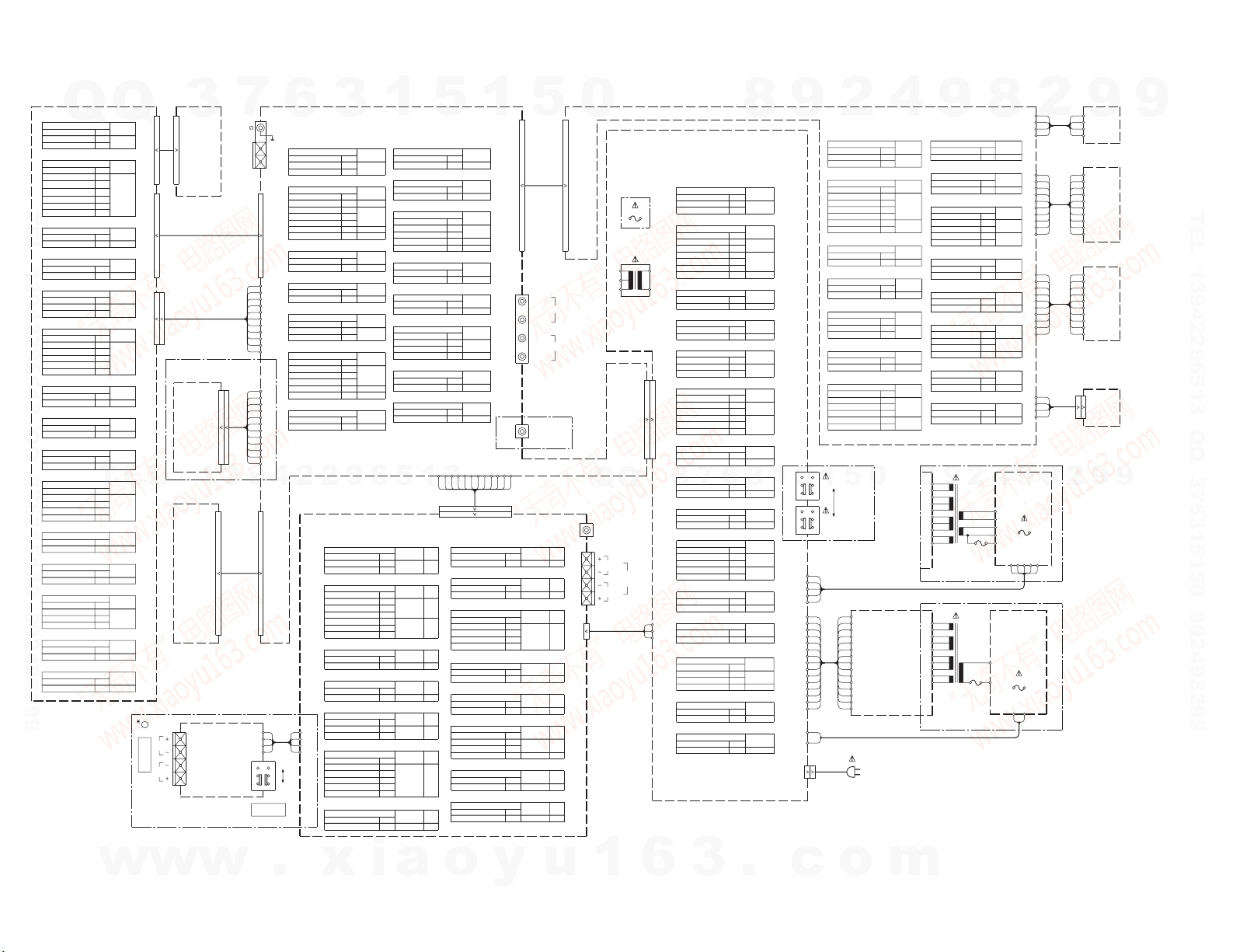
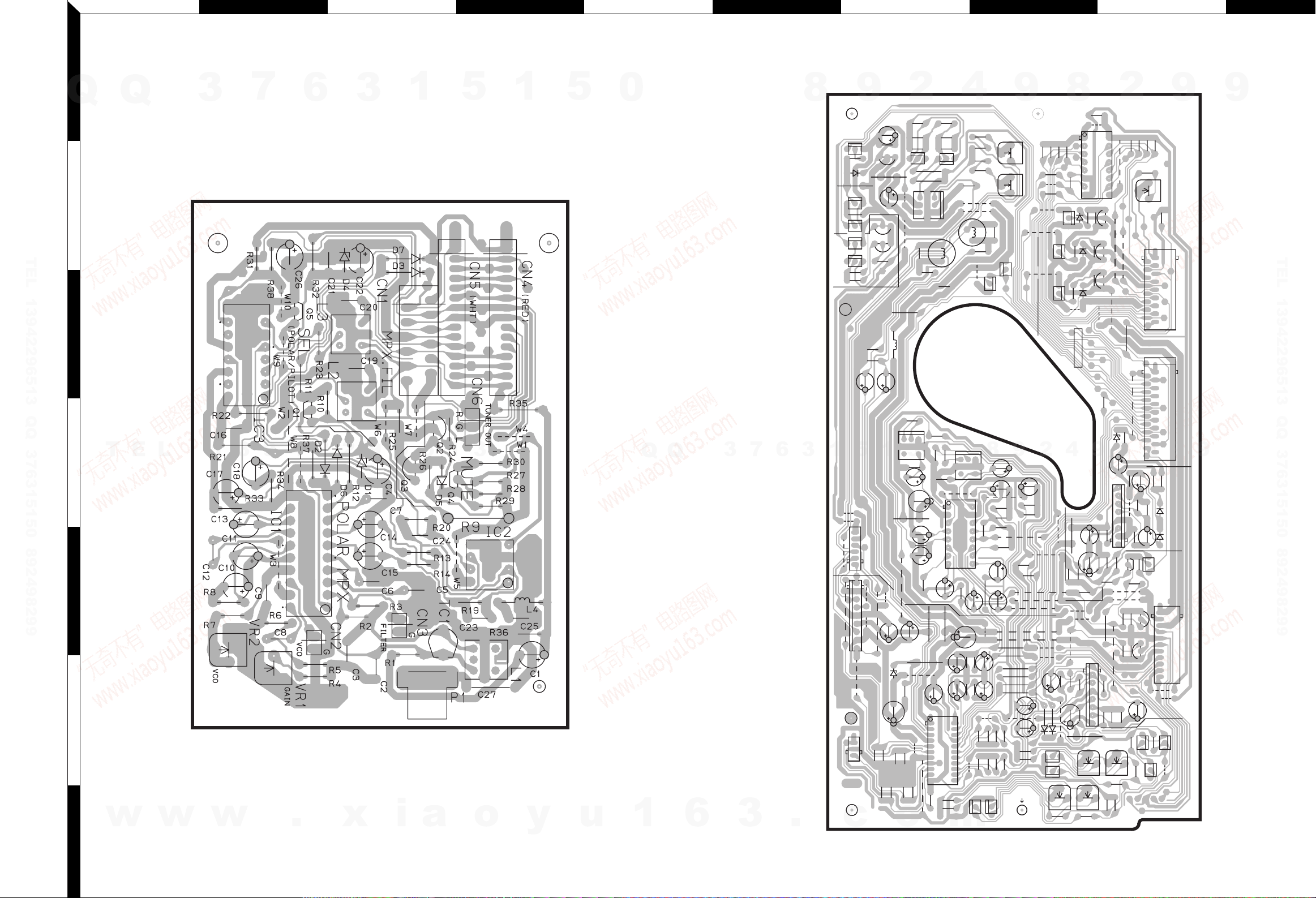
PC BOARD(Component side view
1
7
3
6
9
4
.
2
2
x
3
9
6
i
Q
Q
3
2
TEL 13942296513 QQ 376315150 892498299
3
4
5
6
T
E
w
7
L
w
MPX UNIT
1
w
Refer to the schematic diagram for the value of resistors and capacitors.
)
1
5
a
1
5
3
o
1
y
5
u
0
1
Q
15
Q
6
3
7
3
6
.
RECORD/PLAYBACK UNIT
1
2
5
o
0
8
3
1
9
5
c
4
m
8
9
9
2
8
4
9
2
8
2
9
9
9
TEL 13942296513 QQ 376315150 892498299
9
16
 Loading...