

Page 1
MINI HiFi COMPONENT SYSTEM
70%
RXD-355/355-H/355E
RXD-355E-H/355M/355M-H
SERVICE MANUAL
(XD-355)**
This manual is available for M, X and Y types.
Panel ass'y *
(A60-)
© 2001-9 PRINTED IN KOREA
B51-5757-00 (K/K) 533
Panel(CD)
(A60-2090-08)
FL panel *
(B10-)
Cassette lid(L)
(A21-3958-08)
Knob(VOLUME)
(K29-8047-08)
Dress ring
(A21-3966-08)
Cassette lid(R)
(A21-3959-08)
**Refer to page 2 if you want to know system configuration.
In compliance with Federal Regulations, following are reproduction of labels on, or inside the product relating to laser product safety.
* Refer to parts list on page 27.
KENWOOD-Corp. certifies this equipment conforms to DHHS
Regulations No.21 CFR 1040. 10, Chapter 1, subchapter J.
DANGER : Laser radiation when open and interlock defeated.
AVOID DIRECT EXPOSURE TO BEAM.
Page 2
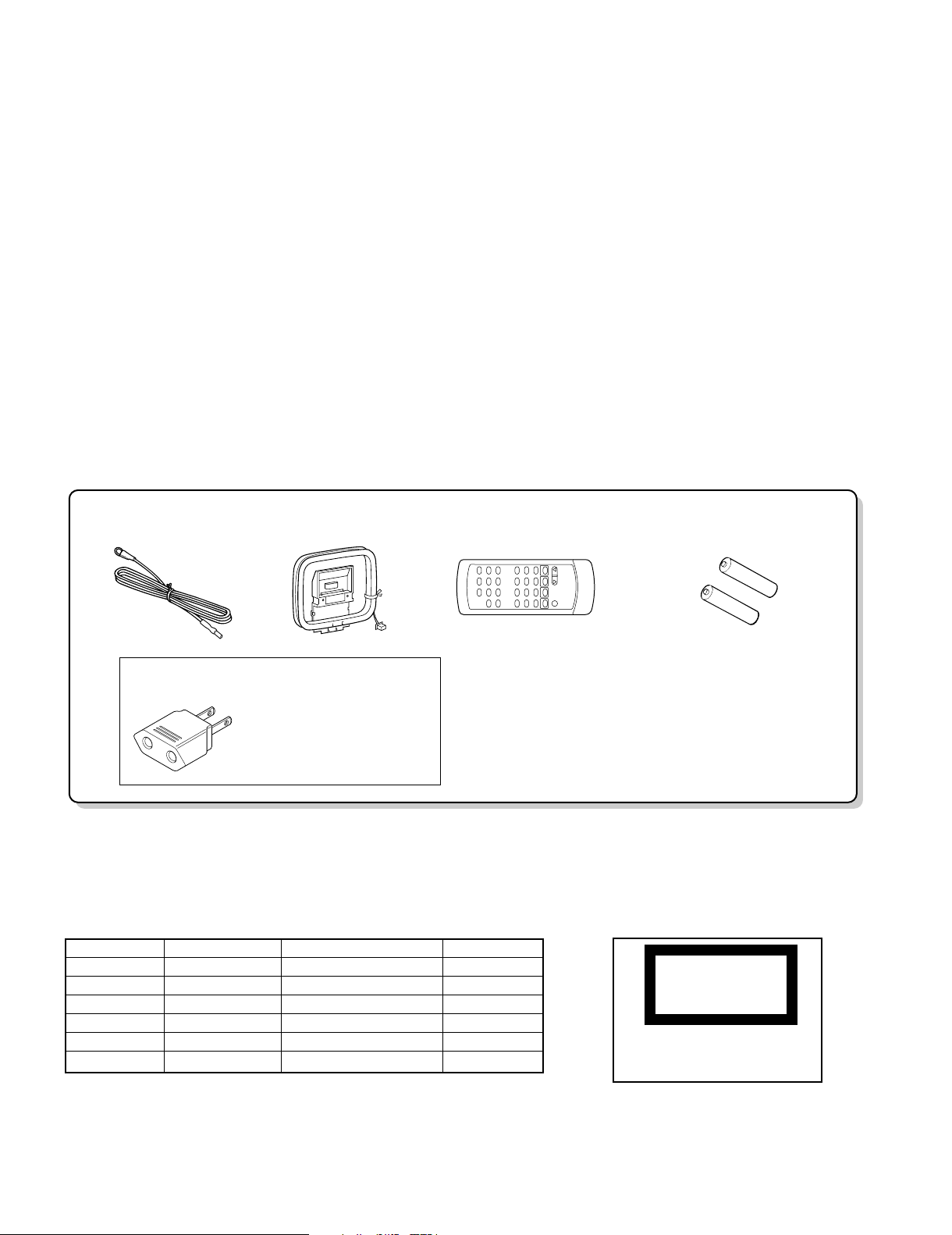
AM Loop Antenna(1)
(T90-0879-08)
“AA” size battery (UM/SUM-3,
R6, HP-7 or similar)(2)
Remote Control(1)
(A70-1531-08): MM1XX1
(A70-1537-08): EE1E2E3T
FM Antenna(1)
(T90-0883-08)
Use to adapt the plug on the
power cord to the shape of the
wall outlet.
(Accessory only for regions where
use is necessary.)
AC Plug Adaptor (1)
(E03-0115-05)
RXD-355
The marking this product has been
classified as Class 1. It means that there
is no danger of hazardous radiati
outside the product.
CONTENTS / ACCESSORIES / CAUTIONS
Contents
CONTENTS / ACCESSORIES / CAUTIONS............. 2
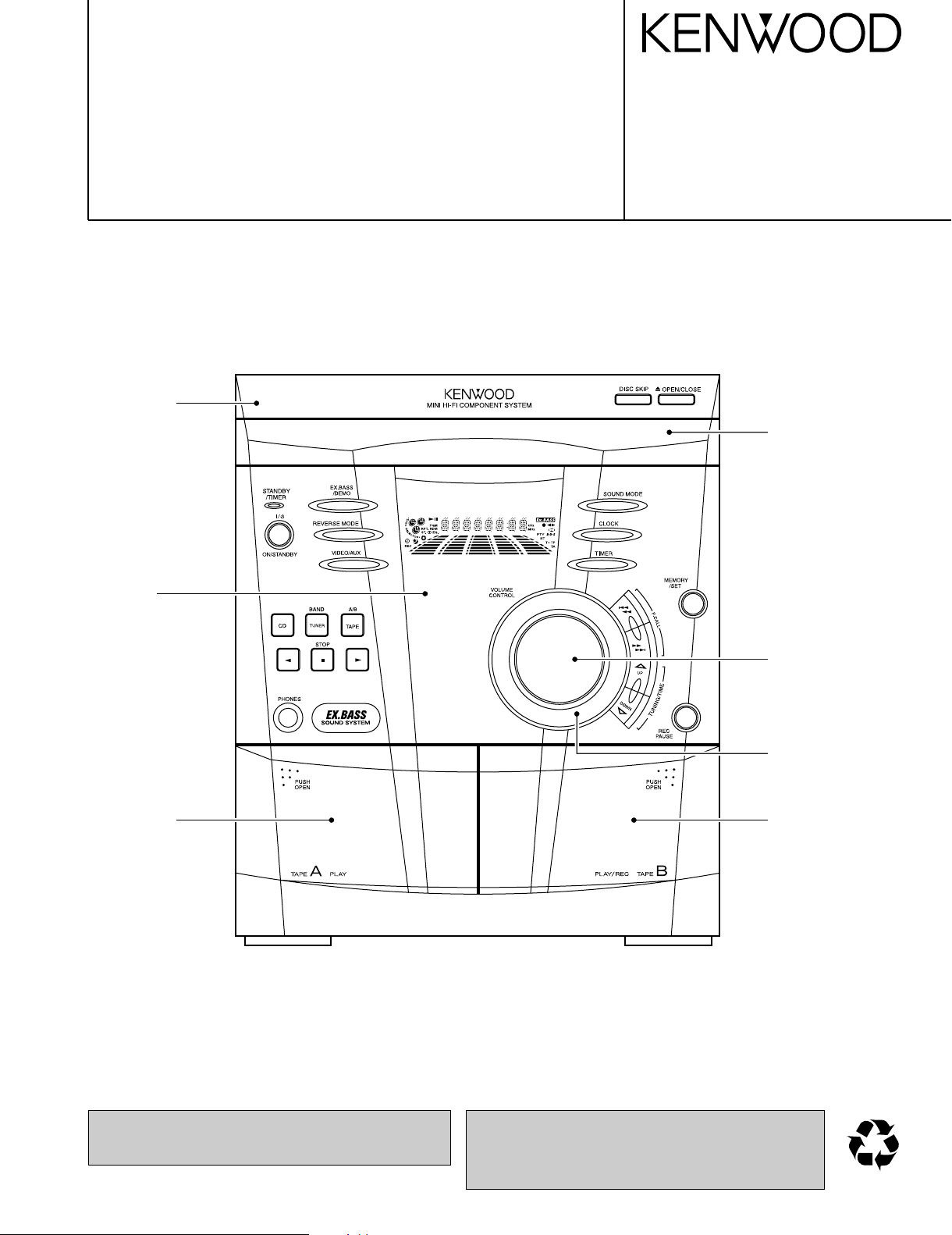
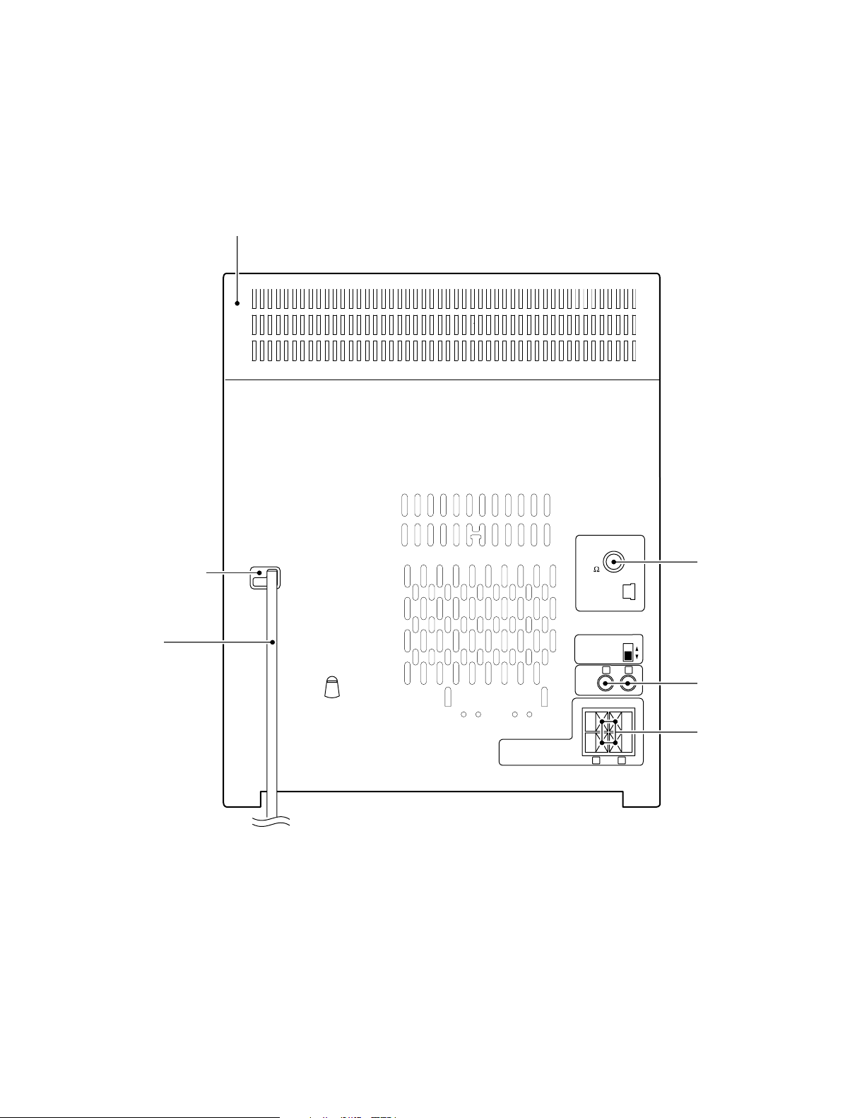
EXTERNAL VIEW .......................................................3
DISASSEMBLY FOR REPAIR....................................4
BLOCK DIAGRAM ......................................................8
CIRCUIT DESCRIPTION ............................................9
ADJUSTMENT ..........................................................12
Attention
Please contact our KENWOOD Service Department in your side if you want the service information; Circuit Description. Full
Described Parts list and so. Information is available to you by internet from us.
Accessories
PC BOARD ...............................................................13
SCHEMATIC DIAGRAM .......................................... 17
EXPLODED VIEW ....................................................25
PARTS LIST..............................................................27
SPECIFICATIONS ......................................Back cover
SYSTEM MAIN UNIT DESTINATIONS SPEAKERS
XD-355 RXD-355 E,T LS-N30S
XD-355 RXD-355M M,X LS-N30S
XD-355E RXD-355E E2 LS-N30S
XD-355E-H RXD-355E-H E3 LS-N30S-H
XD-355-H RXD-355M-H M1,X1,Y1 LS-N30S-H
XD-355-H RXD-355-H E1 LS-N30S-H
2
CautionsSystem Configuration
CLASS 1
LASER PRODUCT
Page 3
ANTENNA
AM
LOOP
FM
75
VIDEO
/AUX
SPAN
SELECTOR
230V
240V
FM 50kHz
AM 9kHz
FM 100kHz
AM 10kHz
++
--
-
L
SPEAKERS
RATED SPEAKER IMPEDANCE:
6 OHMS MIN.
R
LR
Cabinet(TOP)
(A02-3014-08)
RXD-355
EXTERNAL VIEW
AC power cord bushing
(J42-0338-08)
AC power cord
(E30-2881-08)
FM Antenna
(E70-0145-08)
Pin jack
(E63-1219-08)
Lock terminal board
(E70-0151-08)
3
Page 4
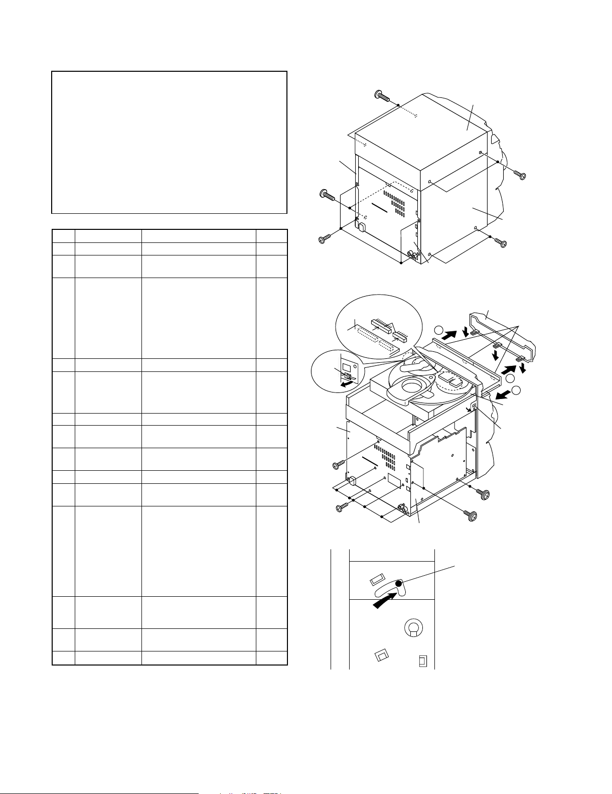
Caution on Disassembly
Follow the below-mentioned notes when disassembling
the unit and reassembling it, to keep it safe and ensure
excellent performance:
1. Take cassette tape and compact disc out of the unit.
2. Be sure to remove the power supply plug from the wall
outlet before starting to disassemble the unit.
3. Take off nylon bands or wire holders where they need be
removed when disassembling the unit. After servicing
the unit, be sure to rearrange the leads where they were
before disassembling.
4. Take suffcient care on static electricity of integrated
circuits and other circuits when servicing.
Figure 7-2
Figure 7-3
1 Top Cabinet 1. Screw ..................... (A1) x4 7-1
2 Side Panel 1. Screw ..................... (B1) x8 7-1
(Left/right)
3 CD Player Unit/ 1. Turn on the power supply, 7-2
CD Tray Cover open the disc tray, take out
the CD cover, and close.
(Note 1)
2. Screw ..................... (C1) x1
3. Hook ....................... (C2) x3
4. Hook ....................... (C3) x2
5. Socket .................... (C4) x2
4 Rear Panel 1. Screw ..................... (D1) x9 7-2
5 Main PWB 1. Screw ..................... (E1) x1 7-2
2. Socket .................... (E2) x3 8-2
3. Flat Cable .............. (E3) x1
4. Tip Wire .................. (E4) x1
6
Power Supply PWB
1. Flat Wire ................. (F3) x1 8-3
7 Display PWB 1. Screw .....................
(H1) x9
8-3
2. Socket .................... (H2) x1
8 Tape Mechanism 1. Open the cassette holder. 8-3
2. Screw...................... (J1) x5
9
Headphones PWB
1. Screw ..................... (K1) x1 8-3
10 Turntable 1. Hook ....................... (L1) x2 8-4
2. Cover ..................... (L2) x1
11 Disc Tray 1.
Turn fully the lock lever in the
7-3
arrow direction.
2.
While holding the lock lever,rotate
8-1
the cam gear until the cam gear
rib engages with the clamp lever.
3.
Push the slide holder backward to
8-5
engage the claw with the groove
and remove it in the direction
of the arrow. ..............
(M1) x6
12 CD Servo PWB 1. Screw ..................... (N1) x1 8-6
(Note 2) 2. Hook ....................... (N2) x2
3. Socket .................... (N3) x4
13 CD Mechanism 1. Hook ....................... (P1) x2 9-1
2. Hook ....................... (P2) x3
14
Loading Motor PWB
1. Hook ....................... (Q1) x5 9-1
STEP
REMOVAL PROCEDURE
FIGURE
Figure 7-1
Note 1:
How to open the changer manually. (Fig. 7-3)
1. In this state, turn fully the lock lever in the arrow direction
through the hole on the loading chassis bottom.
2.
While holding the lock lever, rotate the cam gear anticlockwise
until the cam gear rib engages with the clamp lever.
(Fig. 8-1)
3. After that, push forward the CD slide holder.
Note 2:
1. After removing the connector for the optical pickup from the
connector, wrap the conductive aluminium foil around the
front end of the connector so as to protect the optical pickup
from electrostatic damage.
Note 3:
1. Be careful not to break the claw of the CD mechanism.
2. When fining back the cam gear assembly, let it lock by front
movement.
RXD-355
DISASSEMBLY FOR REPAIR
4
Side Panel
(Right)
(B1)x2
ø3x10mm
(B1)x4
ø3x10mm
(C3) x1
Pull
Rear
Panel
(C1)x1
ø3x10mm
(D1)x7
ø3x10mm
(A1)x2
ø3x12mm
CD Servo
PWB
(C4)x2
Main PWB
Rear
Panel
1
(D1)x2
ø3x10mm
LOCK LEVER
Top Cabinet
DC Tray Cover
(E1)x1
ø3x10mm
(A1)x2
ø3x12mm
Side Panel
(Left)
(B1)x2
ø3x10mm
(C2) x3
1
2
CD Player
Unit
(C3)x1
Page 5
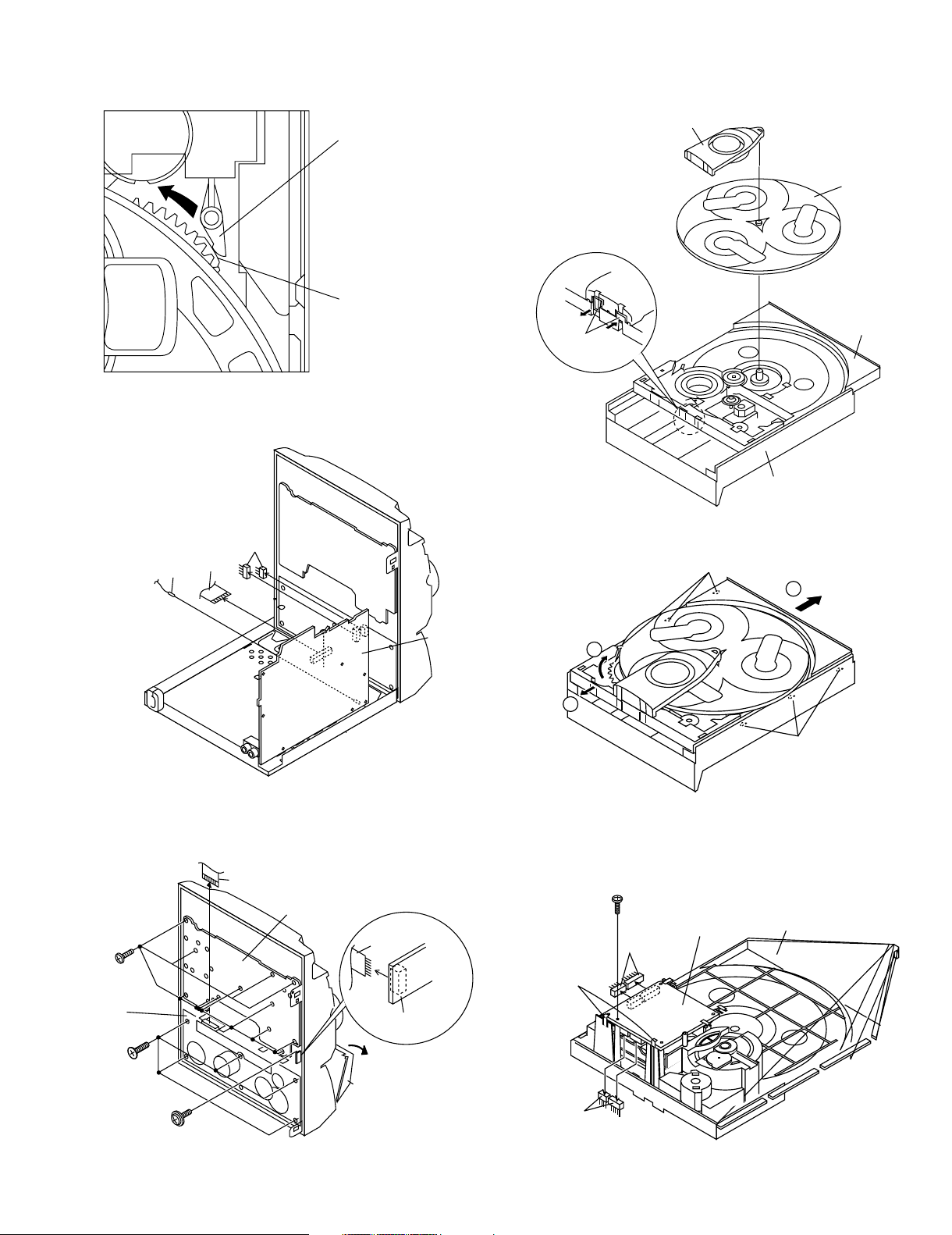
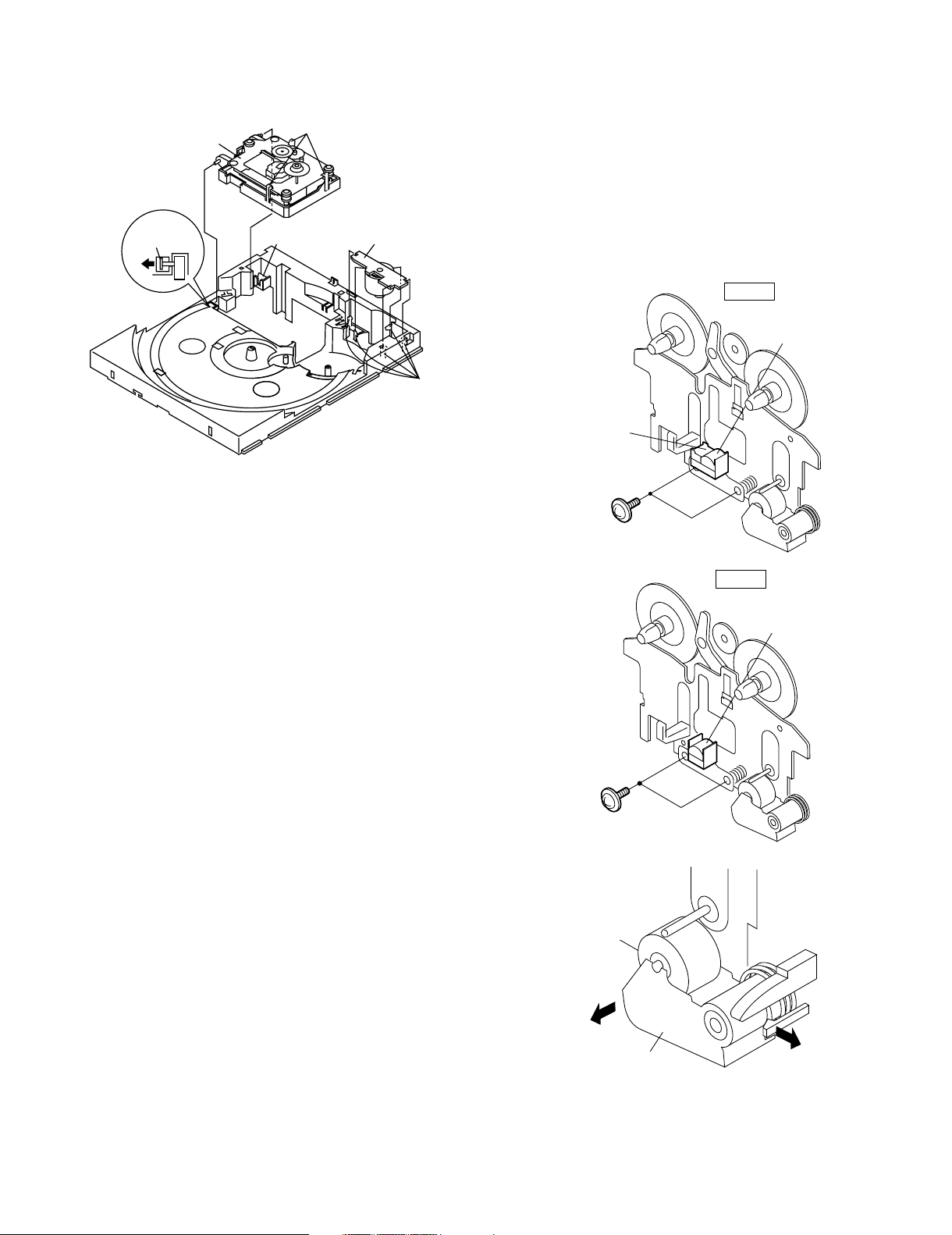
Figure 8-1
Figure 8-2
Figure 8-3
Figure 8-4
Figure 8-5
Figure 8-6
CLAMP LEVER
CAM GEAR RIB
(E3)x1
(E4)x1
(E2)x2
Main PWB
(H1)x9
ø3x10mm
(H2)x1
(J1)x5
ø3x10mm
(K1)x1
ø3x10mm
(F3)x1
Display PWB
Headphones
PWB
Open
Cassette
Holder
Tape
Mechanism
Turntable
Disc Tray
(L2) x1
CD Player Unit
(L1) x2
1
3
2
(M1) x3
(M1) x3
(N3) x2
(N2) x2
(N3) x2
CD Servo
PWB
CD Player
Base
(N1)x1
ø3x8mm
DISASSEMBLY FOR REPAIR
RXD-355
5
Page 6
RXD-355
Figure 9-1
(P2) x3
(P1) x1
(Q1) x5
(P1) x1
Loading
Motor
PWB
CD
Mechanism
REMOVING AND REINSTALLING
THE MAIN PARTS
TAPE MECHANISM SECTION
Perform steps 1 to 7 and 9 of the disassembly method to
remove the tape mechanism.
How to remove the record/playback and erase
heads (TAPE 2) (See Fig. 10-1)
1. When you remove the screw (A1) x 2 pcs., the recording/
playback head and three-dimensional head of the erasing
head can be removesd.
How to remove the playback head (TAPE 1)
(See Fig. 10-2)
1. When you remove the screw (B1) x 2 pcs., the playback
head.
How to remove the pinch roller (TAPE 1/2)
(See Fig. 10-3)
1. Carefully push the inside claw to remove it. The pinch roller
pawl in the direction of the arrow <A>, and remove the pinch
roller (C1) upwards.
Note:
When installing the pinch roller, pay attention to the spring
mounting position.
How to remove the belt (TAPE 1) (See Fig. 10-4)
1. Remove the main belt (D1) x 1 pc., from the motor side.
2. Remove the FF/REW belt (D2) x 1 pc.
Figure 10-1
Figure 10-2
Figure 10-3
(A1)x2
Ø2x9mm
TAPE2
Record/Playback
Head
Erase Head
(B1)x2
Ø2x9mm
TAPE1
Playback
Head
Pinch Roller
(C1)x1
<A>
STEP1
STEP2
DISASSEMBLY FOR REPAIR
6
Page 7
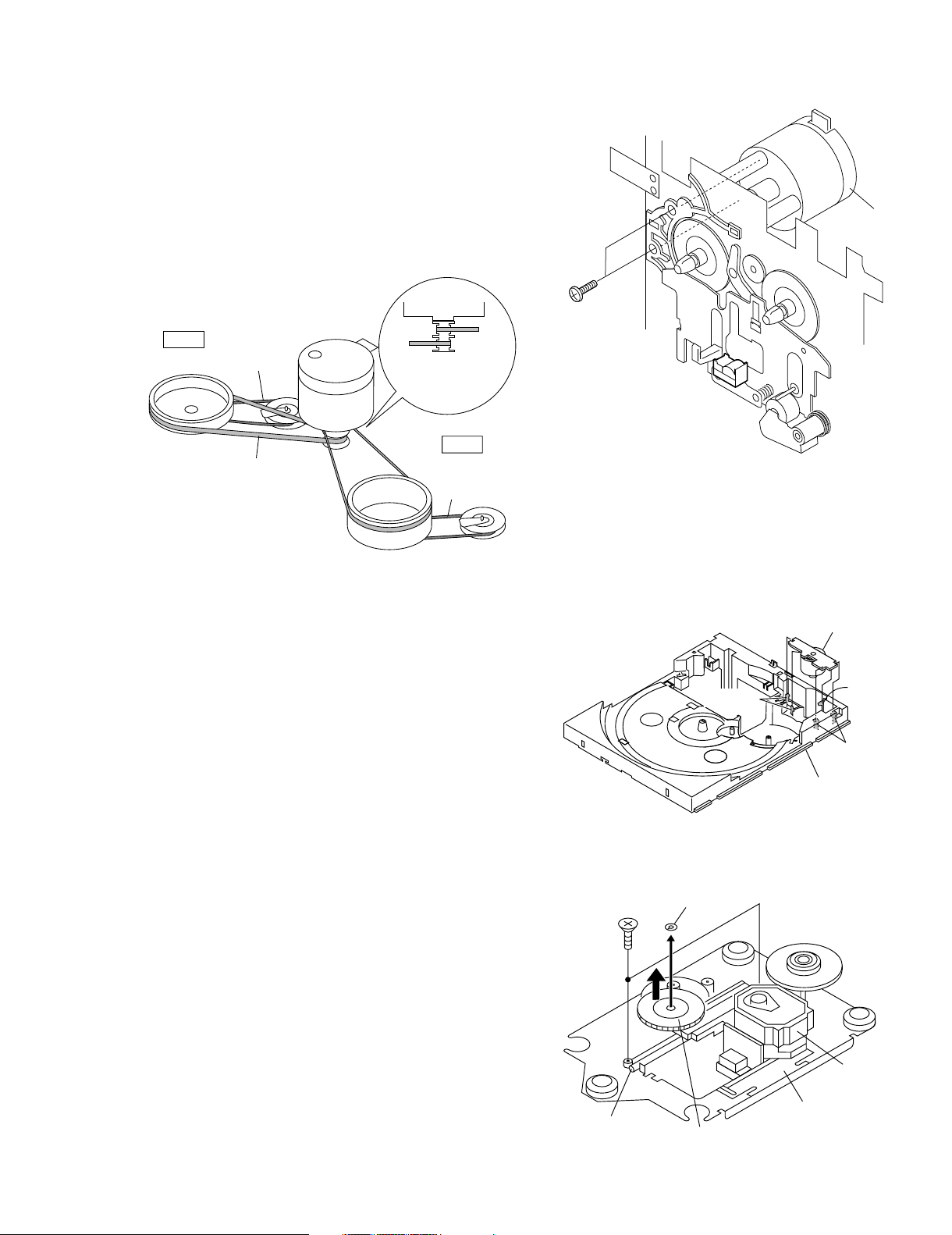
How to remove the pickup (See Fig. 11-2)
1. Remove the stop washer (B1) x 1 pc., to remove the gear
(B2).
2. Remove the screws (B3) x 2 pcs., to remove the shaft (B4).
3. Remove the pickup.
Figure 11-2
CD MECHANISM SECTION
Perform steps 1, 2, 3, 11 and 14 of the disassembly method
to remove the CD mechanism.
How to remove the loading motor
(See Fig. 11-1)
1. Bend the hooks (A1) x 5 pcs., to remove the loading motor.
Figure 11-1
Note
After removing the connector for the optical pickup from the
connector wrap the conductive aluminium foil around the front
end of connector so as to protect the optical pickup from
electrostatic damage.
How to remove the belt (TAPE 2) (See Fig. 10-4)
1. Remove the main belt (E1) x 1 pc., from the motor side.
2. Remove the FF/REW belt (E2) x 1 pc.
How to remove the motor (See Fig. 10-5)
1. Remove the screws (F1) x 2 pcs., to remove the motor.
Figure 10-4
Figure 10-5
TAPE2
TAPE1
Main Belt
(D1)x1
TAPE2
Main Belt
(E1)x1
TAPE1
Main Belt
FF/REW
Belt
(E2)x1
FF/REW
Belt
(D2)x1
Motor
Motor
(F1) x2
Ø2.6x5mm
Motor
DISASSEMBLY FOR REPAIR
RXD-355
Loading Moter
(A1)x1
(A1)x2
(A1)x2
(B3) x2
ø2.6 x6mm
Shaft
(B4) x1
CD Base
Stop Washer
(B1) x1
Pickup
CD Mechanism
Gear
(B2) x1
7
Page 8
2
6
7
4
8
1
5
3
22
23
21
14
4
1
2
9
5
17
16
OUT
IN
GND
VCC
MPX IN
AM OSC IN
AM OSC OUT
AM RF IN
5
3
4
21
20
1
152216
6
OSC
1
3
2
9
10
7
16
15
13
12
14
11
R
L
R
L
R
L
R
L
17
3
+B4
FM
OSC
AM IN
FM IN
FM OSC
FM+B
214R
L
8
18
AUX
TAPE
CD
TUNER
L
R
23
+B4
R
L
24
2
3
4
6
9
16
T1/T2
REC
13
4
5
7
18
VCC
1
+B3
+B3
23
14
12
21
20
P.B
H/N
17
8
15
19
NOR/
HIGH
T1/T2
+B4
L
R
L
R
10
L NF
R NF
ALC
REF
R REC
R NF
L REC
POP REDUCE
R(T2)
L NF
R(T1)
L(T2)
L(T1)
+B4
+B4
REC
VH+
VH-
151R
L
9
13
7
108R-OUT
L-OUT
SP.DET.
12-14
25-36
15-24
4-11
1,2
38,39
10
6
7-9
1
2
21
56
58
59
575554
4950484746
43
42
67-78
79
80-89
90-92
93-100
52
53
51
45
44
41
40
38
39
36
37
25
33-31
34
35
11
16
13
12
17-20
+B7
+B7
+B7
+B7
+B7
VDD
VLOAD
RESET
VDO
22
23
24
CECLDO
DI
VDD
AVDD
+B6
BIAS
T1/T2
REC
1
2
3
+B7
+B3
+B6
-
-
+
+
R-CH
L-CH
+B1
M12V
+B2
A10V
VF2
+B4
63Hz
30
7
-B2
4
1
8
10Hz 1K
29
28
VF1
+5V
CD+B
+B3
T1/T2
P.B
REC
P.B
4
5
TV
FM IF IN
REG
3
+B4
8
192018
FM/AM
OUT
15
L
R
12
11
10
12 IF IN
13
6
SD
10
13
FM MONO/ST
11
7
STEREO
MONO/ST
IF OUT
24
IN
OUT
AFC
AM RF IN
+B4
17FM
+B4
6
CE
DI
CL
DO
16
2
4
8
3
7
151413
11
10
9
63-66
MPX IN
VSSA
VDDA
RDS-ID
RDCL
RDDA
RST
XIN
VDDD
VSSD
XOUT
AM RF
31
31
31
2
POWER AMP.
IC901
TERMINAL
AM LOOP ANT
FM FRONT END
FE301
CF301
FM IF
FM IF
COVERAGETRACKING
AM AM BAND
T303 T306
T351
IC303
FM/AM IF MPX.
LA1832S
X351
456kHz
PLL(TUNER)
LC72131
IC302
4.5MHz
X352
Q360
CNS11
from CD SECTION
CNP1
LC75341
IC401
AUDIO
SO401
VIDEO/
M
IC101
Q703
Q704
Q705
54PIN
IC700
IC700
56PIN
53PIN
IC700
55PIN
IC700
MOTOR
DRIVER
TAPE MECHANISM
ASSEMBLY
SOLM1,SOLM2
SOLENOID
MM1
MOTOR
TAPE
SWM2
T2 PLAY
R.PLAY
SWM4
SWM1
T1 PLAY
SWM3
F.PLAY
AN7345K
/PLAYBACK AMP.
PLAYBACK
Rch
Lch
Rch
Lch
TAPE 1
TAPE2
PB HEAD
REC/PB HEAD
SWITCHING
Q103-106
SWITCHING
108
AC BIAS
Q111
Q109
Q113
Q110
SWITCHING
Q121,122
MUTING
SWITCHING
ERASE
HEAD
Q114,L104
BIAS OSC
SWITCHING
Q112
BIAS
AM IF
-20dB
ATT
SYSTEM
MUTE
604 402
Q901-
FL701
DISPLAY
IC700(1/2)
SYSTEM
UPD780206
708
Q706-
MICROCOMPUTER
Q700
RESET
XL701
4.1943MHz
VR701
JOG
RX701
SENSOR
REMOTE
KEY0-2
to CD
SECTION
JK981
HEADPHONES
M
M901
FAN MOTOR
Q971
DRIVER
Q951
RL951
SO901
TERMINAL
SPEAKER
T801
TRANSFORMER
F801
T4A L 250V
F802
T4A L 250V
D809
D802-805
Q813
F803
T2AL 250V
KIA7810AP
REGULATOR
VOLTAGE
IC812
ZD810
T2AL 250V
F804
KIA4558
MICROCOMPUTER
IC700(2/2)
OPE
AMP.
562
SYSTEM
UPD780206
IC811
Q875
D801
D872-875
T802
SUB POWER
TRANSFORMER
RL801
AC POWER
SUPPLY CORD
AC 230V 50Hz
UNSWITCH 5V
VOLTAGE
MAIN POWER
AUX IN
AND RECORD
Q107,
PROCESSOR
Q603, Q401,
IC561,
904
ANTENNA
SO301A
Q301
AMP
FM IF
CF302
FM IF
CF351
L.P.F
L354
QT21
AMP
L341
BALUN
REGULATOR
LC72723
IC304
4.332MHz
XT21
RDS DECODER
STK402-070
D876
D831
KIA7805AP
VOLTAGE
REGULATOR
REGULATOR
CONSTANT
AN78L05
IC852
VOLTAGE
FILTER
LINE
L801
SOCKET
AC INPUT
SO801
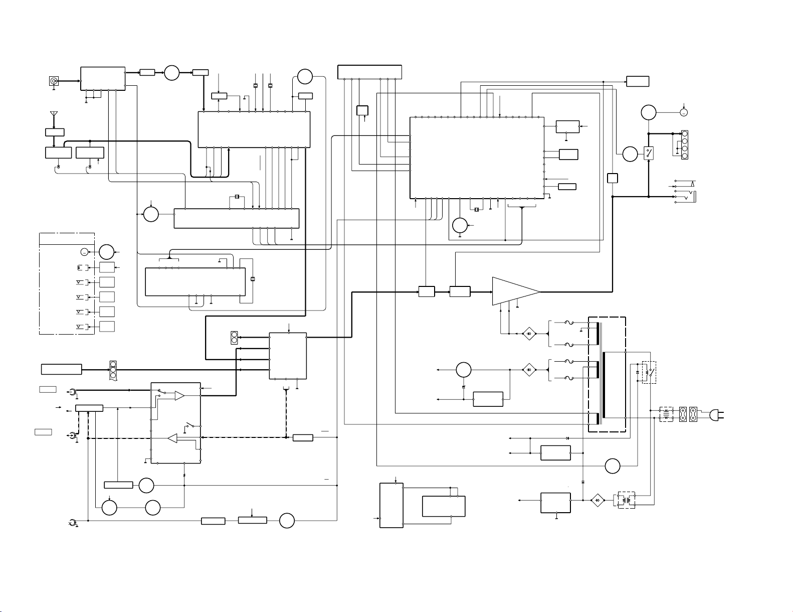
RXD-355(E,T)
8
RXD-355
BLOCK DIAGRAM
Page 9
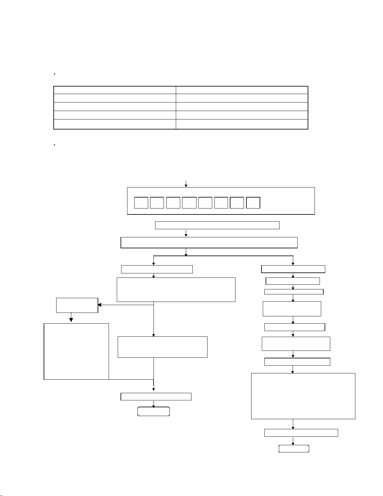
Enter the Test Mode
OPEN/CLOSE operation is using manual
<< $ ! >>, << ⁄ › >> buttons make pick's slide possible.
<< PLAY >> key input << MEMORY >> key input
Do TOC IL. Do normal play
Laser ON.
When these following key is input
into PLAY key, track number can << MEMORY >> key input
be appoint directly
Tracking OFF play at that
specific point
<< MEMORY >> key input
Remote Controller Only
<<DISC 1>> key: Track 4 Tracking ON play from that
<<DISC 2>> key: Track 9
specific point
<<DISC 3>> key: Track 15
<< MEMORY >> key input
<< STOP >> key input
STOP
<< STOP >> key input
STOP
XX :Hex value
Sliding the PICKUP with
<< $ ! >>, << ⁄ › >>button
must only be in STOP mode.
D ST E TC
Adjustment result automatically will
display as below for each 2 sec :
a)"FOFF__XX"
b)"TOFF__XX"
c)"TBAL__XX"
d)"TGAN__XX"
f)"FGAN__XX"
g)"RFLS__XX"
CIRCUIT DESCRIPTION
1. Test Mode
1-1 How to Set up the Test Mode
During POWER OFF mode, push below each 2 keys and [POWER] key.
Then go to each TEST MODE.
KEYS TEST MODE
[ POWER ] [ SOUND ] + [ CD ] CD TEST MODE
[ POWER ] [ SOUND ] + [STOP ] ALL CLEAR (RESET)
[ POWER ] [ TUN DOWN ] + [ TUNER ] PRODUCTION INITIALIZE FOR CHANGER
[ POWER ] [ REC ] + [ CD] CD CHANGER TEST
1-2 Cancelling the Test Mode
Turn the power off.
1-3 Contents of the Test Mode
1-3-1 CD Test Mode
RXD-355
<< MEMORY >>
key input
Adjustment result
automaticallywill
display as below
for each 2 sec :
a)"FOFF__XX"
b)"TOFF__XX"
c)"TBAL__XX"
d)"TGAN__XX"
f)"FGAN__XX"
g)"RFLS__XX"
9
Page 10

RXD-355
Function: - Software RESET.
- All the function condition will be initialize.
- It will jump to A operation in case of power ON.
- After display "CLEAR ALL", power will off.
- Forwarding condition set for CD changer.
- Forwarding condition set for TAPE mecha.
"CLEAR_AL" display
L E A R LAC
Function: The SET will
be set to
"shipping
- All the function, condition are initialized.
- CLEAR ALL TUNER PRESET MEMORY .
- CLOCK INITIAL
- CLEAR CD MEMORY
- Initialize the CD changer mecha and compact cassette mecha.
- For CD changer mecha, set the CD mecha in upward condition.
Display, key input
"WAIT" display
"FINISHED" display
When initialize the mechanism, it will display "WAIT" and will not accept any changes in input
After "shipping condition" setting is ended, "FINISHED" is displayed and any key input will be prohibited.
If there are any troubles and "shipping condition" cannot be set, "ERR" will be displayed.
TW A I
I HN I S DEF
1-3-2 Software Reset
1-3-3 Initializing the CD changer
CIRCUIT DESCRIPTION
10
Page 11

START
" " KEY
TRAY OPEN IF THE ERROR OCCURS,
GO TO ERROR MODE
DISC SKIP
DISC SKIP
DISC SKIP
TRAY CLOSE
DISC X PLAY
DISC SKIP
DISC Y PLAY
DISC SKIP
DISC Z PLAY
2. Standard Specification of Stereo System Error Message Display Contents
Error Contents Display Notes
Output while Device Protection Operation 'PROTECT'
Due to over current detection or unit in protect circuit operation.
DSP Control Error 'ER-AP**'
10:DSP Control Error (general)
TAPE Mechanism Error 'ER-TA**'
00:Tape Mechanism Error
01:Initial Error
CD/VCD
Pick-Up Mechanism Error 'ER-CD**'
00:Pick-up Mechanism Error
01:PU-IN SW Detection NG
CD Changer Mechanism Error 'ER-CD**'
10:Changer Error
11:Initial Error
Tray Error 'ER-CD**'
20:Tray Error
Focus Not Match 'NO DISC'
Micon Communication Error 'ER-CD**'
30:System-VCD
31:Syatem-CD Servo
TUNER
PLL UnLock 'ER-TU**'
00:TUN Error
01:PLL Unlock
RDS Connection WEAK SIG Signal is too weak to receive.
1-3-4 CD Changer Aging Test Mode
RXD-355
CIRCUIT DESCRIPTION
11
Page 12

RXD-355
SO301
FM ANTENNA
AM LOOP
ANTENNA
T303
IC301 í AM
TRACKING
✽
R381
ï
TP301
T306
✽ solder side view
ï
AM BAND
T351 COVERAGE
TP302
ó R357
AM
ADJUSTMENT POINTS
(Component Side View)
TUNER SECTION
fL : Low-range frequency
fH : High-range frequency
• AM IF/RF
Signal generator : 400HZ, 30%, AM modulated
Test Stage Frequency Frequency Display Setting/Adjusting Parts Instrument Connection
AM IF 450kHz 1620kHz T351 ✽1
AM Band Coverage - 522kHz (fL) : T306 1.1±0.1V ✽2
AM Tracking 990kHz 990kHz (fL) : T303
✽ 1. Input Antenna Output : TP302
✽ 2. Input Antenna Output : TP301
ADJUSTMENT
✽1
12
• FM
Notes
1. Description of the "FM IF Adjustment" is not carried on this manual.
It is because the IF coil in the FM front end section has been best adjusted in the factory so that its further adjustment is
not needed at the field. When replacing the FM front end assembly, no adjustment is needed either.
2. The parts in the FM front end section are prepared in a complete unit, so you can't obtain each part individually.
Page 13

C430
C429
C402
C401
C937
C938
C338
C615
C616
C106
C120
C113
C126
C132
C121
C127
C133
C115
C137
C104
C107
C105
C102
C103
C112
C114
C145
C143
C414
C413
C435
R418
R417
C444
C445
MJ413
MJ412
MJ410
MJ414
MJ801
C443
C337
C397
R325
R302
C310
C302
C311
R327
C312
C309
R313
C308
C314
C303
C313
C324
R311
C304
C306
R322
MJ305
C305
C315
R316
C317
C316
C392
C381
C387
C385
C323
C395
C355
C356
C334
C336
C335
C384
C354
C399
C301
C353
C344
C350A
C351
C342
C361
C366
C363
C382
C330
C332
C369
TP302
MJ315
C319
C302
C340
C386
R365
R422
R421
R425
R401
R402
R403
R404
R407
R935
R936
R931
R932
R616
R615
R619
R118
R134
R103
R147
R144
R110
R104
R126
R132
R130
R121
R135
R136
R101
R102
R131
R129
MJ101
R133
R119
R123
R106
R113
R108
R109
R107
R120
R111
R105
R112
R128
R137
R127
R125
R148
R122
R141
R124
C441
R415
C442
R416
R614
R424
C375
R380
R379
R372
R383
R385
R376
R359
R381
R373
R374
R352
R323
R353
R355
R388
R351
R362
R361
R356
R377
R360
R393
R395
R378
TP301
R427
R428
R903
R336
MJ306
R972
C972
EB
E
E
B
B
E
E
B
B
E
B
E
B
E
B
E
1
2
19
20
B
E
B
1
13
19
11
22
12
1
1
BE
BE
24
13
1
1
E
B
E
B
E
71
E
B
GOI
GBEOIGOI
E
B
B
E
B
BEBEBEB
E
B
E
B
E
3
12
6
12
2413
E
B
EB
C933
C928
C922
R973
C920
R982
CF302
C352
T351
T301
T302
C394
X352
L351
R382
R375
J425
J426
R423
J402
J401
C423
J107
R143
J106
C139
L101
C129
C135
C131
R140
R139
C150
C138
C134
R142
J109
C130
C144
C128
C116
L102
C118
R117
R116
R149
C148
C141
C119
R145 J102
J101
R157
J830
J819
J821
J825
J828
J831
J832
J834
J836
J838
J840
J841
J839
J837
J835
J833
J829
J826
J827
J822
J824
J820
R408
J403
C406
C440
J418
J419
J420
J421
J416
J415
J417
10 1
J414
J413
J412
J411
J422
J423
J427
J307
J428
J429
J430
J431
J432
R410
J404
J441
J405
J406
R429
R431
R430
J316
J424
C617
J861
J860
C407
C409
C411
C417
C421
C419
J407
J408
C123
J105
C122
C117
R115
C136
R114
J104
J103
C108
L104
C142
C140
C101
R146
R138
J409
J410
C427
C425
C428
C426
C424
C422
C420
C418
C388
C404
C408
C410
C412
T303
21
C331
C926
R926
R927
C921
R916
R917
C915
R915
R908
J903
J904
C980
J905
R916
C913
R911
C907
R909
R981
R981
J843
C902
J847
R363
R364
C935
C403
C374
C350
J310
J525
R370
X351
CF351
J312
J313
J302
J440
J437
J439
R613
J436
R409
J434
J435
J433
J305
L352
J306
C370
J304
J303
R350
R309
R314
C367
C373
J849
R904
R902
C904
J845
R910
R804
C811
C812
J806
BI901
J807
C813
R807
R806
J812
J863
J811
R833
C836
J808
113
J815
J901
J805
J902
R919
R980
C910
C940
C914
J908
C923
C929
R924
C925
R923
C924
C929
L921L920
R922
R953
C954
C955
C916
R954
HD951
15
R907
R905
LG902
R901
R920
C911
R978
C909
C912
J852
C816
C817
C812
J804
C853
J801
J802
J803
J859
C808
C810
LUG961
C815
C809
LG904
J858
J810
J809
J862
J857
R811
R851
C849
C873
R834
J853
C936
R934
R933
C906
C905
C901
C372
R357
C365
C364
R358
J317
J308
1
CF352
J318
J309
C326
C393
TP301
C380
R387
R392
C398
C357
C358
R391
R384
R386
C391
C396
C307
C362
L312
T306
C368
C371
1
12
115
24
13
J850
C818
R814
R815
C852
R906
C908
C820
R912
R979
C903
R913
C917
J906
R420
R419
C971
R971
RL951
C927
C934
R921
J910
240V 220V
127V110V
FH808
FH806
FH804
J854
C803
C802
FH802
FH801
FH803FH805
FH807
5
R951
J856
J855
C806
C805
R884
R885
F804
F803
F802
T4A L 250V
T4A L 250V
T2A L 250V
T2A L 250V
F801
R952
J927
1
1
6
13
1
K801
K802
J918
J917
J916
J915
J920
J914
J919
IC401
BI11
BI403
CNP101
Q103
Q109
CNP701
Q111
IC852
Q603
Q604
Q401
CNP901
CNP951
JK951
PHONES
D803
D805
D804
D802
D809
S0801
CNP905
Q971
CNP302
S0301A
D303
D304
Q360
E
B
Q302
VD302
IC302
D302
D301
BF301
VD301
VD303
IC301
FW951A
ZD351
S0901
L
SPEAKERS
R
AUX-IN
SPAN
SELECTOR
AM
FM
ANTENNA
S0401
SW601
CNP2
D951
Q951
Q904
IC303
Q903
D971
D305
Q901
IC812
Q813
ZD810
Q902
IC811
D901
IC901
D902
ZD904
D903
IC101
CNS102
Q102
Q101
Q107
Q105
Q104
Q106
Q114
Q110
Q112
Q113
Q108
Q801
ZD801
ZD802
ZD803
D808
D807
D806
Q402
D851
BI901
D831
D833
ACEG IBDFHJ
PC BOARD(Component side view)
1
2
3
4
5
6
7
Refer to the schematic diagram for the value of resistors and capacitors.
13 14
Page 14

IC700
R744
R761
R765
R763
R772
RD03
RD02
R783
R778
R779
R780
R747
R771
R766
R767
R768
R769
R770
R756
R752
R706
R705
R704
R575
R577
R572
R569
R578
R565
R567
R576
R568
R566
R777
R776
R759
R758
R757
R773
R745R743
R742
RD05
RD01
R561
R570
R571
R562
R574
R580
RD08
RD09
RD15
RD07
RD10
RD12
RD06
RD13
RD16
RD11
R787
R731
R774
R760
R762
R764
R700
R573
R741
R740
R739
RD04
R790
C703
C705
C706
C573
C572
C569
C710
C715
C711
C716
C709
C568
C567
C562
C561
C566
C565
C571
MJ6
MJ3
MJ2
MJ5
MJ7
MJ1
MJ4
R750
1
30
31
50
51
80
81
100
RD17
RD18
Q706
Q708
Q707
SW703
SW701
SW706
SW702
SW715
DISPLAY SECTION
SW707
SW708
SW720
FW701 B
SW721
SW709 SW710
SW705
SW719
SW717
SW704
SW716
SW711
SW712
SW713
SW714
ZD561
IC561
IC562
LED712
RX701
Q712
D700
D702
D701
D703
FL701
D718
D516
D514
D513
D717
D707
D706
D709
D710
D708
D515
BI2
BI8
Q704
Q705
BI905
SW718
FW701 A
CNS701
CNS702
D711
Q700
Q703
Q709
Q713
LED700
LED709
C704
C700
C702
C701
C707
C563
C564
C570
C708
R563
R564
C717
XL700
VR701
J717
J718
J719
J723 J721
J728
R579
J701
J702
J703
J704
J705
J707
J708
J779
J780
R701
R703
R702
R709
R710
R711
R712
R713
R714
R715
R716
R708
J720J722
J724
R720
R718
R719
J748
R726
R727
R728
R725
R781
R724
J749
J706
R729
R733
R734
R737
R738
R736
R775
R735
J744
J745
J746
J737
J743
J755
R788
R717
J754
J736
J757
J758
J759
J752
J756
R786
J761
J751
J786
R707
J713
J716
J711
J753
J732
J735
J734
R784
J714
J733
R804
R805
J725
R801
R802
R803
J709
J710
J700
J712
R794
R791
R792
R793
J742
R730
RD14
J762
J739
J740
J771
J770
R721
J738
J727
J726
J784
J783
J782
J781
J776
J777
J772
J715
J741
J763
J731
J730
J729
R782
J769
J768
J767
J764
J765
R746
J778
J785
J773
J774
J775
L700
J760
R732
R748
J750
J766
C719
R723
R722
J747
R789
R749
C712
R751
C713
A75
A55
A35
755M
655M
355M
755L
655L
355L
R785
755/E
655/E
355/E
POWER
EX-BASS
REVERSE
MODE
AUX
CD
TUNER
TAPE
REC
TUNING
DOWN
TUNING UP
VOLUME
MEMORY
TIMER
CLOCK
EQU
1
2
9
10
13
16
1
2
25
26
1
39 38 24136
9
EB
EB
B
IOG
E
BE
BE
BE
BE
BE
BE
BE
C718
14
85
1
4
8
5
13
DISC SKIP
O/C
K LNPRTMOQS
PC BOARD(Component side view
)
1
2
3
4
5
6
7
15 16
Refer to the schematic diagram for the value of resistors and capacitors.
Page 15

ACEG IBDFHJ
IC1
IC2
CD MOTOR PWB-D
PICKUP UNIT
CD SECTION
FOCUS/TRACKING/
SPIN/SLED DRIVER
D2
D1
Q3
SERVO/SIGNAL
CONTROL
CNP8
CNP7
ZD2
Q2
CONSTANT
VOLTAGE
CNS4CNP4
OPEN/
CLOSE
DISC
NO
CLAMP
LOADING
CNS1ACNS1B CNP1
CNS2ACNS2B CNP2
CNS3ACNS3B CNP3
M
M
SPINDLE
MOTOR
SLED
MOTOR
PICKUP IN
LASER
DRIVER
Q1
CNP3A
IC1 : LC78645E
IC2 : M63001FP
Q1 : KTA1266GR
Q2 : KTC3203Y
Q3 : KRC102M
D1,2 : 1SS133
ZD1 : MTZJ3.3B
ZD2 : MTZJ3.9B
B LINE
B LINE
GND LINE
SIGNAL LINE
RECORDING LINE
ZD1
M
1
2
8079787776
75747372717069
68
67
66
65
64
63
62
61
60
59
58
57
56
55
54
53
52
51
50
49
48
47
46
45
44
43
42
41
21
22
232425
2627282930
31
32
333435
3637383940
1
2
3
4
5
6
7
8
9
10
11
12
13
14
15
16
17
18
19
20
LDD
LDS
FR
VVDD
PCKIST
VVSS
PDO2
PDO1
NC
CONT2
CONT3
VSS
VDD5
DRF
RES
WRQ
DO
DI
CL
CE
NC
NC
NC
ASDFIN
ASDACK
ASLRCK
NC
NC
NC
XVSS
FSX/16MIN
XIN
XOUT
XVDD
RVDD
RCHO
RVSS
LVSS
LCHO
LVDD
FDO
SPDO
SLDONCCONT4
CONT5NCSBCK/FGNCNCNCNCNCNCNCNC
VSS
VDD
DOUT
TEST
SLC0
SLCIST
EFMIN
RF
RFVDD
RSVSS
FIN1 A
FIN2 B
TIN1 E
TIN2 F
VREF
REF1
NC
TEC
NC
NC
JITTC
ADAVDD
ADAVSS
TDO
212019
18
17161514131211109876543
2
1
MUTE
VREF
STAND
VCC
SLDO
SL+
SL-
GND
GND
GND
GND
GND
GND
TR-
TR+
FO-
FO+
NC
FD
TO
22
23
24
25
2627282930
31
32
333435
36
37
383940
41
42
GND
VCC
VCC2
SPO
SP+
SP-
VCC3
GND
GND
GND
GND
GND
GND
GNDNCNC
M-M+VCC4
LD M-
LD M+
GND
BY
4
5
6
7
21
20
15
16
220u6.3
C40
+
R44
12K
+
C39
100u10
27
26
39
38
R45
470
470
R46
70
71
R11
10K
0.047
C5
0.1
C6
C7
100P R12
330C84700PC50
22P
TP1
TP2
100u10
+
C9
10u10
+
C10
0.22u50
+
C11
100P
C12
R13
1K
R10
27K
TP3
1K
R14
1K
R15
R16
1K
1K
R17
1K
R18
100u10
C14
+
0.022
C13
R20
10K
15P
C20
15P
C19
220
R43
XL1
33.8688MHz
0.82uH
L1
R22
100
2.2K
R25
10u50
+
C24
1500P
C26
R27
10K
10u50
+
C23
2.2K
R24
1500P
C25
10K
R26
1000P
C44
+
C49
47u25
1000P
C4
+
C3
47u25
3.3
R9
R42
1.2K
12K
R41
0.1
C37
680
R40
2.2u50
C36
+
R39
680
C35
0.047
R28
2.2K
2.2K
R29
71
70
0.022
C27
C34
100P
1K
R38
67
66
100P
C33
R37
1K
64
65
100P
C32
R35
R36
1K
1K
62
61
100P
C28
C30
100P
63
R34
1K
R33
R32
1K
1K
R31
1K
1
2
3
4
5
6
7
8
9
WRQ
DRF
CE
DO
DI
CL
CD RES
CLAMP
O/C. DISC NO
65
67
61
64
63
62
66
8
9
5 +5V
6 +5V
4 DGND
3 L-CH
12R-CH
AGND
0.01
C42
0.022
C51
R23
220
+
C18
100u10
Q2
R49
1
23
20
21
23
1
2
3
4
5
6
1
2
3
4
5
66
3
4
5
1
2
38
39
R19
15K
R30
8.2K
8
9
R7
47
7
6
5
4
3
2
1
VCC
VREF
E
A
B
F
C
7
6
5
4
3
2
11
7
4
2
3
5
6
1
7
4
3
2
6
5
8
LD
6
5
4
PD
GND
FO-
3
2
1
TR+
FO+
TR-
7
VR
1
2
3
4
5
6
7
88
7
6
5
4
3
2
11
2
3
4
5
6
7
8
FO-
FO+
TR+
TR-
11
GND
11
2
3
4
2
PUIN
22
SL-
33
4
SL+
4
3
4
5
6
SP+
5
SP-
5
66
5
6
M1
M2
SW4
12K
R2
R6 33K
R1
12K
R5 12K
R3 33K
R4 12K
6
5
4
7
0.01
C38
0
R48
+
C1
47u25
0.01
C2
16
15
27
26
C48
0.022
100u10
+
C41
B
+B
AC TUATOR
330u16
+
C16
+5V
+5V
+5V
+5V
+5V
+5V
+5V
+5V
+5V
+5V
+5V
+5V
+5V
+5V
+5V
+5V
+5V
5.0V
3.2V
3.2V
5.0V
3.2V
3.5V
3.5V
3.9V
3.2V
4.7V
4.7V
5.0V
5.0V
AM-1
V-2
The DC voltage is an actual reading measured with a high impedance type
voltmeter with a cassette loaded at playback mode. The measurement
value may vary depending on the measuring instruments used or on the
1
product. Bias circuit DC voltage is measured while in the record mode.
DOLBY and the double-D symbol are trademarks of Dolby Laboratories
Licensing Corporation. Noise reduction circuit made under license from
Dolby Laboratories Licensing Corporation.
2
3
4
CAUTION: For continued safety, replace safety critical components only
with manufacturer's recommended parts (refer to parts list). indicates
safety critical components. For continued protection against risk of fire,
replace only with same type and rating fuse(s). To reduce the risk of electric shock, leakage-current or resistance measurements shall be carried
out (exposed parts are acceptably insulated from the supply circuit) before
the appliance is returned to the customer.
5
The DC voltage is an actual reading measured with a high impedance
type voltmeter. The measurement value may vary depending on the measuring instruments used or on the product. Refer to the voltage during
PLAY unless otherwise specified; The value shown in ( ) is the voltage
measured at the moment of STOP.
The DC voltage is an actual reading measured with a high impedance type volt-
6
meter as the AM/FM signal generator is specified to the conditions as shown in the
list below. The measurement value may vary depending on the measuring instruments used or on the product. The value shown in ( ) is actual reading measured
in the AM mode.
MODE CARRIER
FREQUENCY DEVIATION
MODULATION
FM 98MHz 1kHz STEREO 67.5kHz 7.5kHz(Pilot) 60dB
AM 1000(999)kHz 400Hz MONO 30% MOD 60dB
7
ANT INPUT
Page 16

K LNPRTMOQS
IC401
MECHA BASE
IC302
IC303
TUNER/MAIN SECTION
IC304
FE301
IC301
AUDIO PROCESSOR
Q603
Q604
Q401
Q402
SYSTEM MUTE
-20dB ATT
Q102
Q103
Q101
REC/PLAY
Q108
Q109
Q104
Q106
Q107
Q105
CNS102
CNP101
SWITCHING
ERASE
Rch
Lch
Rch
Lch
PLAYBACK
HEAD
RECORD/
PLAYBACK
HEAD
TAPE 2
TAPE 1
ZD351
PLL
SW
FM
Q360
IF
MPX/AM
DET/FM
FM IF
CNP701
AM IFT
ERASE
HEAD
ZDT21
QT21
RDS
DEMODULATOR
CNP302
AM
3
CHASSISCHASSIS
CNS101
CNS102
FM FRONT END
Q301
ANTENNA
SO301
FM
TRACKING
AM
VD301
AM BAND
COVERAGE
FM FRONT END
D305
VD302
VD303
(M,X,Y)TYPE ONLY
ANTENNA
FM
ANTENNA
AM
BF301
(E,T)TYPE
RDS SECTION
(E,T)TYPE
ONLY
(E,T)TYPE ONLY
SW601
(M,X,Y)TYPE ONLY
ONLY
(E,T)TYPE
ONLY
(E,T)TYPE ONLY
ANTENNA
Q302
(W02-2876-08)
CCB
INTERFACE
AUX
DECK
CD
TUNER
D1
1
CE
2
3
VSS
L OUT
4
L BASS
5
6
L TRE
L IN
7
L SELO
8
L4
9
L3
L2
11
10
L1
12
1
T1 T1
24
2
T2
NF
3
T2
23
22
NF
1u50
+
C425
1u50
+
C421
1u50
+
C417
47P
C441
10K
R417
R427
1u50
+
C427
1u50
+
C423
4.7u50
+
C419
3.9K
R415
0.15
C411
0.1
C409
10u50
+
C407
C413
1500P
1
2
10K
1000P
C616
1000P
C615
2.2K
R616
2.2K
R615
2.2K
R408
330
R614
3.9K
R404
1000P
C402
1000P
C401
3.9K
R403
2.2K
R407
330
R613
22K
R425
+
C403
22u50
+
C617
2.2u50
22K
R619
330
R401
330
R402
100K
R118
1K
R114
330P
C114
330P
C112
+
C108
100u16
56
R116
100u25
+
C116
0.033
C118
4.7K
R103
10K
R101
10K
R102
0.033
C119
100K
R119
330P
C113
100u25
+
C117
1K
R115
330P
C115
5.6K
R123
56
R117
5.6K
R125
560P
C107
560P
C106
2.2K
R107
3.3K
R109
3.3K
R108
4.7K
R111
47K
R113
4.7K
R112
2.2K
R106
47K
R110
180P
C104
180P
C105
1
2
3
4
5
6
7
M GND
ERASE
T2 R2
A GND
T2 R1
T2 L1
T2 L2
T1 R
A GND
T1 L
2
3
1
560P
C102
560P
C103
1K
R105
1K
R104
150
R157
Q101,104-109
6
7
3
5
4
2
1
3
2
1
5.6K
C385
X352
FM IN
VDD
A OUT
X OUT
R387
15P
5
6
3
4
1K
R372
1K
R373
R374
1K
R386
22K
R378
1K
C382
FM/AM
DO
CL
CE
NC
X IN
5
DI
4
3
2
1
7
6
C381
12P
VSS
202122
PD
A IN
16
17
18
19
+
R379
2.2K
150
R382
C387
C392
1000P
C380
10u16
R380
1.5K
TP301
C393
1u50
R381
10K
+
+
C394
47u16
C397
0.022
AM IN
R359
1.8K
4.7K
R360
R376
47u16
C391
R384
5.6K
8
9
10
1K
+
5.6K
ST IND
MO/ST
FM/AM
IF CONT
11
10
9
8
R385
R383
5.6K
R391
270
R392
270
IF IN
SD
NC
12
13
14
15
330P
0.01
C386
C396
100u10
C395
0.022
R377
47K
0.022
L351
100uH
+
R351 5.6K
PHASE(FM/AM)
AM MIX OUT
R393 1K
CF352
C353 0.022
C350 0.022
10u16
C352
T351
+
R352
1K
3
2
1
6
5
4
REG
FM IF IN
SD
GND
AM IF IN
R388
C356
1000P
C399 0.022
C354 0.022
8
9
10
C398
CF351
22P
C355
100u10
+
R355
3.3K
+
R353
270
3.9K
+
C357
2.2u50
9
8
7
C358
1u50
11
10
VCC
FM DET
STEREO
PHASE
IF OUT
12
1u50 2.7K
C365 0.022
C366 1000P
C363 0.022
C364
4.7u50
R358
C361 0.022
AM LOW CUT
AM RF IN
AM OSC IN
AM OSC OUT
FM AFC
VSM
3.9K
21
22
23
24
19
20
+
C367
C342
0.022
R365
10K
+
C362
3.3u50
R350
2.7K
R363
R364
2.7K
0.027
0.027
C369 27P
C374
C373
Lch OUT
Rch OUT
MPX VCO
FM/AM OUT
MPX IN
MO/ST
16
17
18
14
15
C372
X351
+
C368
1u50
+
+
1u50
+
C371
1u50
13
R361
2.2K
R362
2.2K
R356
1K
TP302
R357
470K
SP DET
16 2019
NC
NC
1817
SPAN
SP RLY
1514
SW +5V
- 20dB
131211
- 15V
M +12V
A GND
REC/
8109
SPA SIG
S MUTE
7
T T1 T2
CLK2DO
465
T BIAS
D GND
3
DI
1
CE
24
1
R431 1K
2
R430 1K
R429 1K
6
3
4
5
6
7
8
C150
22u25
+
10
16
17
1u50
+
47K
R395
1000P
C388
15K
R137
15V
15V
15V
+12V
+12V
+B
+B +B
+B
+B
+B
+B
+B
+B
+B
+B
+B
+B
+B
+12V
+B
L354
TUN SM
RDS-
21 22
RDS-
RDS-
RDS-
NC
23 24 25 26
9
10
11
12
13
14
15
16
XIN
VSSD
VDDD
MODE
RST
RDDA
RDCL
RDS-ID/
8
7
6
5
4
3
2
1
XOUT
TEST
CIN
FLOUT
VSSA
VDDA
MPXIN
VREF
READY
22P
CT23
4.332MHz
22P
CT25
XT21
CT22
0.022
47u10
CT21
+
1K
RT27
RT28
1K
1K
RT29RT32
6.8K
10K
RT31
13
RT21
10K 1K
RT30
2.2uH
LT21
560P
CT26
0.022
CT27
47u10
CT31
+
0.022
CT28
0.022
CT29
LT22
2.2uH
47u10
+
CT32
390
RT22
390
RT23
1/4W
1/4W
10u16
CT24
+
RT25
10K
56K
RT24
56K
RT26
6
4
212
1
2
L341
1
3
0.022
CT30
20
131415
16
1K
16
15
14
20
2.2uH
L102
2.2uH
L101
6.8K
R409
8
C445
220P
220P
C444
24
READY
RDCL
RDDA
RST
PLAY
IF OUT
470
R375
C341
0.022
R348 680
C348
0.01
R349 33
L342
2.2uH
R347
6.8K
C346 0.022
C321 100u16
C345 0.022
R345 4.7K
R301 0
C347 0.022
R344 470
CF301
4
R346
1
330
GND
F OUT
VT
2
3
6
VCC
GND
+
R369
15
5
GND
ANT
7
8
+B
3
5
1
26
4
T306
560P
C335
R323 68K
C334 27P
0.047
C331
0.022
C332
T303
C323
0.022
6
1
C330
4
5
15P
32
R336
10K
1
243
567
9
3
2
1
11
22
33
10P
C303
8
0.01
C304
C305
4.7P
10u16
C307
+
C306
0.022
L312
4.7P
C308
100K
R311
1000P
C309
R314
22
4700P
C314
C315
4700P
1000P
0.022
C317
C316
R313
33K
R327
33
R325
47K
100P
C318
T301
0.022
C312
T302
15P
C310
10
R302
18P
C311
C324
3.9P
C313
22P
10K
R309
4.7K
R316
CF302
9kHz 10kHz
50kHz 100kHz
CF302
R322
680
+B
+B
+B
+B
+B
+B
+B
+B
R370
C370
1000P
C337
C375
1000P
1000P
C319
1000P
C326
L352
1000P
C302
C101
0.047
0V
3.4V(3.6V)
2.3V(2.0V)
(2.0V)
1.8V
5.0V
2.3V
0V (2.4V)
2.4V
(1.8V)
2.3V (0.2V)
2.0V
1.2V
1.2V
FM ST : 3.9V
MONO : 2.2V
2.0V
5.0V
2.0V
2.0V
0V
MONO : 5.0V
2.9V (3.7V)
0V
FM ST : 0V
4.9V (5.1V)
3.8V(1.2V)
(1.9V)
3.8V
2.5V
0.7V
0.7V
5.0V
2.5V (0V)
(2.5V)
0V
0.1V
2.4V
2.4V
(9.9V)
0V
(0V)
3.8V
3.9V
MONO :
0V
FM ST :
5.0V
0V
8.3V (0V)
(10.0V)
9.3V
10.0V
12.2V
5.0V
5.0V
5.0V
5.0V
5.0V
5.0V
5.0V
5.0V
5.0V
REC : 9.8V
PLAY : 8.0V
REC : 9.8V
PLAY : 7.3V
PLAY : 0V
REC : 9.8V
REC : 0V
PLAY : 4.0V
0.5V
0V
0V
0.6V
ON : 0V
OFF : 5.1V
ST IND
3.0V 3.1V
6.2V
5.5V
8.3V
3.1V
6.2V
3.1V
3.0V
2.5V
6.2V
7-30 : 0V
VOL.
0-6 : 1.4V
OFF : 0V
MUTE ON : 1.3V
10.0V
PLAY : 0V
REC : 3.7V
PLAY : 7.9V
0V
0V
0V
0V
0V
0V
0V : 0.7V
PLAY
5.0V
3.0V
0V
0V
0V
0.7V
7.8V
: 4.2V
FM 98MHz
7.7V
8.3V
4.9V(5.1V)
AM-3
Page 17

ADUWYAAACVXZAB
IC101
IC901
POWER SECTION
HEADPHONES OUT
TUNER/MAIN SECTION
IC812
IC811
IC852
M
PLAYBACK
REC EQ.
Q110 Q111
Q113
Q112
Q114
BIAS
OSC
BIAS
MUTING
BI11
Lch 1
Rch 2
AUX IN
SO401
POWER
AMP
Lch
6 ohm
SP
SO901
D951
Q951 D971
Q971
M
M901
FW951
D809
D805
D803
D804
D802
D801
CNP905
SP.
RELAY
DRIVER
FAN
MOTOR
TAPE MECHA.
ASSEMBLY
CNP901BI901
BI801 CNP801
D877 ZD871
D876
D872D875
D873D874
ZD810
Q813
+10V
AVR
D833 ZD803
D831
D851
D806 D807
D808
ZD802
D901
Q901
Q902
D902
D903
Q903
Q904
ZD904
AVR
+5.6V
+5V AVR
Q801
-30V
AVR
AVR
+12V
SP. DET.
SP.RELAY
CNP951
GND
GND
Rch
HEADPHONES
2
4
IC301 : TA7358AP
IC302 : LC72131
IC303 : LA1832S
IC304 : LC72723M
IC401 : LC75341
IC852 : AN78L05
IC812 : KIA7810AP
IC901 : STK40270N
Q101,360 : KTA1266GR
Q102,103,113 : KRC104M
Q104-107 : 2SC1845F
: KTC3199GR
Q112 : 2SA1015GR
Q114,971 : KTC3203Y
Q301 : 2SC380-0
Q801 : KTA1274Y
Q813 : KTC2026
Q951 : KRC107M
D801,831,833,851,876,
877,901-903,951,971
: 1SS133
D802-808,872-875
: 1N404S
D809 : TS6B04GM
ZD810 : MTZJ2.4B
ZD904 : MTZJ13B
ZD803 : MTZJ11B
ZD801 : MTZJ30B
ZD871 : MTZJ4.3B
ZD351 : MTZJ5.1B
ZDT21 : MTZJ13B
:QT21 KTC3199GR
CHASSIS
ZD801
Q875
AC
CONT.
RELAY
POWER
RELAY
ZD802 MTZJ6R2B:
VD301 C02-0303-08:
ONLY
(E,T)TYPE
SW801
ONLY
(,X,YM)TYPE
IC101 AN7345K:
Q302 KTC3194Y:
VD302,303 : C02-0000-08
K801
K802
IC811 KIA7805AP:
Q108-111,401,402,603,
604,875,901-904
PLAY SWB
GND
T2 RUN
T MOTOR
T SOL B
T SOL A
FPA
T1 RUN
FPB
PLAY SWA
1
2
3
4
5
6
7
8
9
10
F-REC
END SW1
R-REC
SOL1
MTR +
END SW2
SOL2
GND
PLAY SW2
PLAY SW1
CLK
24
VREF
22
R OUT
21
R BASS
20
R TRE
19
R IN
18
R SELO
17
R4
16
R3
15
R2
R1
13
14
VDD
23
Hich=T1
112K
112K
OUT4NC
5
6
21
OUT
SELECT
19
NC
20
56K
56K
Hich=CHROME
REC IN
7
8
OUT
9
REC IN
18
17
OUT
16
T1/T2
15
N or/CrO2
NC10ALC
11
14
RIPPLE
13
VCC
GND
12
22u50
+
C406
1u50
+
C426
1u50
+
C422
1u50
+
C418
0.15
C412
0.1
C410
6.8K
1u50
+
C428
10K
R418
1u50
+
C424
4.7u50
+
C420
10K
R410
10u50
+
C408
3.9K
C414
1500P
5.6K
R122
1u50
+
C122
3.9K
R120
560P
C120
5.6K
R124
R126
C126 270P
22u50
+
R130
6.8K
R128
C134 47u25
+
C132 3300P
C136 22u50
+
C138 220u10
+
1.2K
10K
R141
10K
R140
560P
C121
3.9K
R121
1u50
+
C123
C127 270P
R129
6.8K
R127
+
C139
3.3u50
0.022
C137
1.2K
0.022 100
+
22u25
10K
R135
+
C135
47u25
3300P
C133
R133C131
R131 C129
4.7K
220
R139
15K
R138
+
C142
47u25
8200P
C140
330uH
L104
0.039
C141
4.7
R149
0.047
C148
22K
R148
47K
R147
82
R146
4.7K
R145
47K
R144
1/2W
1
2
3
4
5
6
R-ch
A GND
L-ch
CD GND
CD +B
1
2
3
4
5
6
2.7K
R420
2.7K
R419
680P
C430
15K
R422
680P
C429
15K
R421
470K
R424
220K
R142
1
2
3
4
5
6
7
8
9
10
11
12
13
14
15
ch.1 IN
BIAS
ch.1+VE
ch.1-VE
+VCC
-VCC
ch.2+VE
ch.2-VE
PRE -VCC
SUB GND
ch.2 NF
680P
C901
22u16
+
C905
0.22u50
+
C935
1K
R931
820
R903
R901
56K
4.7
1/4W
C915
0.22
C913
0.22
RL951
R954 2.2K
R953 2.2K
1K
R971
4.7
R982
15K
R973
+
C972
10u50
68K
R972
+
C971
47u50
1
2
3
4
5
150 C
TF801
T801
FH801
T4.0A L 250V
FH802
F801
FH803FH804
T4.0A L 250V
F802
FH805FH806
T2.0A L 250V
F803
FH808FH807
T2.0A L 250V
F804
0.1
C803
0.1
C802C806
0.047
C805
0.047
RL801
T802
C801
4700P
: AC240V~ 50Hz
AC230V~ 50Hz
(X)
: AC110-120V/220-240V~
50/60Hz
(Y,M)
-VP
5
AC RLY
VF2
UNSW
P IN
2431
VF1
6
10
220K
R143
470K
R423
100
C130
0.022
C128 R132
R134
R136
10K
5
4
3
2
1
JK951
Q951
68K
4.7K
+B
+B
+B
+B
+B
+B
+B
C925
0.022
0.0223.9
R921
R924
5.6
0.022
C927
0.022
0.29uH
L920
0.022
C926
0.022
0.022 3.9
R922
C924
0.022
R923
5.6
0.29uH
L921
1000P
C928
1000P
C929
2W
2W
2W
2W
68
681000P
C933
1000P
C934
L801
EQ
REC
EQ
REC
R416
R428
47P
C442
7
1
2
3
4
5
6
7
8
9
10
11
12
13
V+
V-
GND
P IN
REG+B
REG GND
CD+B
-VP
UNSW+5V
P IN
1
2
3
4
5
6
7
8
9
10
11
12
13
SW+5V
AC RLY CTRL
5V+B
UNSW+5V
3
2
1
6
4
1
2
3
6
4
P IN
55
GND
47
R885
47
R884
CTRL
+5V
R881 100
R883 1K
0.1
C875
47K
R882
0.1
C874
1000u6.3
C876
+
0.047
C872
3.3
R811
1/2W
OUT
GND
IN
100P
C817
0.1
C816
560
R814
2200u35
C815
+
22K
R812
R815 22K
C818 0.047
+12V
+B
R834 220K
OUT IN
GND
10K
R851
1000P
C852
+
4700u16
C853
1000P
C849
OUT IN
GND
470u16
C873
+
47K
R833
C809 220u50
+
220u50
C808
+
+
C810 220u50
R804 1K
47u50
+
C811
R806 10
+
C812
47u50
+
C813
100u35
12K
R807
+B
ch.1NFNCPRE +VCC
82P
C937
68K
R933
C903
15P
100K
R935
L-CH
ch.2 IN
R-CH
ch1 ch2
100 1/4W
R919
10u50
+
C911+C912
10u50 100 1/4W
R918
100u50
+
C910
22K
R920
0.22u50
C940
+
0.22 3W
R981
0.22 3W
R980
15K
R911
0.022
C907
0.1 1W
R907
1K
R909
1K
R905
R978
0.22 3W
R979
0.22 3W
100u50
+
C909
R908
0.022
15K
0.1 1W
R912
C908
1K
R910
C917 47u50
+
56K
R914
56K
R913
R915 56K
+
R936
100K
C936
0.22u50
C906
22u16
+
C938
1K
R934
68K
82P
R906
R902
56K
R932
1K
R904
820
C902
680P15P
C904
6
R917
R916
4.7 C914
0.22
C916
0.221/4W
C923 C921C920C922
R927
R926
+12V +12V
+B +B +B
+B
15V
1.8K 1/2W
16
17
3300u50 3300u50
++
C954 C955
R816
220u25
+
C820
L922
2.2uH
R951
330 1/2W
R952
330 1/2W
220P
C978
220P
C979
+B
+B
+B
+5.6V
+B
+B
+12V
+B
+B
+B
+B
+B
+B
+B
+5.6V
B
+5.6V
+B
+B
B
B
B
+5.6V
B
B
+B
B
+B
+B
BB
+B
B
B
+B
+B
+B
C443
220P
100u16
+
C404
+5V
3.3 1/2W
R813
0.1u50
C980
+
+12V
J
230-240V
220V
127V
110V
(E,T)TYPE
ONLY
+B +B
ONLY
(M,X,Y)TYPE
0.7V0.7V
0V
0V
10.0V
5.0V
5.0V
5.0V
5.0V
5.0V
5.0V
5.0V
5.0V
5.0V
5.0V
5.0V
2.0V
B DECK : 0V
A DECK : 2.7V
0V 0.6V
4.2V
2.0V
1.3V
0V
0.6V
3.5V
REC : 6.0V
: 0.5V
REC : 9.8V
PLAY : 0.2V
10.0V
REC : 9.2V
PLAY : 9.9V
PLAY : 9.9V
REC : 0V
REC : 4.7V
PLAY : 0V
5.0V
3.5V
7.0V
REC
33.4V -31.8V 34.2V -34.2V -33.0V
5.7V
TUNER : 10.0V
DECK : 9.9V
CD : 9.6V
20.3V19.9V
5.0V
9.3V
12.2V
34.2V
-34.1V
10.0V
10.0V
2.7V
5.7V
3.8V
-28.7V
-22.8V
POWER ON : 2.7V
5.0V
5.7V
9.3V
12.2V
0.6V
ON : 4.4V
SP.RLY
12.2V
H/P JACK IN : 0V
-12.8V
10.0V
3.8V
12.8V
I-3
AM-2
Page 18

AE AF AH AJ AL ANAG AI AK AM
IC700
RX701
DISPLAY SECTION
RXD-355
(BOTTOM VIEW)
LED700
Q708 Q707 Q706
FL701
GRID
DRIVER
u-COM
BI8
BI905
CNS701
D706
D707
Q700
D709
D710
RESET
REMOTE SENSOR
D711
(2/2)
D513
IC561
D514
(1/2)
IC561
(1/2)
IC562
D516
(2/2)
IC562
D515
ZD561
CNS702
OPE AMP
Q704
SOL.
DRIVER
MOTOR
DRIVER
Q703
Q705
D717D718
SW711 SW712
UP
TUNING
SW713
TUNING
DOWN
SW714
REC
SW715
SET
MEMORY/
SW716
TIMER
SW717 SW719
CLOCK
SW718
EQUALIZER
SW705
TAPE TUNER
SW706CDSW707 SW708 SW709 SW710
POWER VIDEO
SW701 SW702
REVERSE
MODE
X-BASS
SW703 SW704
FW701 BFW701 A
SKIP
DISC
SW720
OPEN/
CLOSE
SW721
VOLUME
LED709
D708
IC561,562 : KIA4558P
IC700 :
Q700,709,712 : KRC102M
Q703 : KTA1273Y
Q704,705 : KTA1271Y
Q706-708 : KTC3199GR
D513-516,700-702,
706-711,717,718
: 1SS133
ZD561 : MTZJ6R2B
LED700 : B30-2613-08(YELLOW)
LED709 : B30-2614-08(RED)
Q709
1
3
4
RX701 W02-2689-08:
ONLY
(E,T)TYPE
KARAOKE
ONLY
(M,X,Y)TYPE ONLY
(E,T)TYPE ONLY
(E,T)TYPE ONLY
TYPE
ONLY
IX0450
(M,X,Y)
818283848586878889
90
91
92
93949596979899
100
1
2
3
4
5
6
7
8
9
10
11
12
13
14
15
16
17
18
19
20
21
22
23
24
25
26
27
28
29
30
50
49
484746
454443
42
41
40
39
38
37
36
35
34
33
32
31
80
79
78
77
76
75
74
73
72
71
70
69
68
67
66
65
64
63
62
61
60
59
58
57
56
55
54
53
52
51
P9
P8P7P6
P5P4P3
P2
P1
G11
G10
G9
G8G7G6
G5G4G3
G2
G1
VDD
-20dB
NO USE/DSA STB
T-BIAS
T T1/T2
REC/PLAY
RES OUT
DRF
WRQ
RESET
X2
X1
VPP/IC
NC
NC
VDD
CD CLK
CD DI
CD DO
CD CE
CE
CLK
DI
DO
AVSS
/DSA DATA
/DSA ACK/TUN SM
SPEANA2
SPEANA1
SPEANA0
T1 RUN
SP DET
SPRLY
AC RLY CONT
VDD
TIMER LED
T MOTOR
T SOL A
T SOL B
SMUTE
VSS
REMOCON
JOG 0
JOG 1
P-IN
AVREF
AVDD
KEY0
KEY1
KEY2
P10
VLOAD
P11
P12
P13
P14
P15
P16
P17
P18
P19/DEST0
P20/DEST1
P21/DEST2
P22/DEST3
RDS-READY/ESS DO/NO USE
RDS-RDCL/ESS DI/NO USE
RDS-RDDA/ESS STB/NO USE
RDS-RST/ESS ACK/NO USE
NO USE/MPEG POW
NC
STAND BY LED
DEST OUT
MP3 LED
MIC IN
FPB
FPA
PLAY SW B
PLAY SW A
SW
T2 RUN
R794 4.7K
XL700
2
C705
15P
C706
18P
4
R701 1K
5
R702 1K
6
R703 1K
7
R704 1K
8
R705 1K
9
R706 1K
R707 1K
17
R709 1K
18
R710 1K
19
R711 1K
20
R712 1K
21
R713 1K
22
R714 1K
23
R715 1K
24
R716 1K
26
R717
28
R791 1K
29
R792 1K
30
R793 1K
1K
R749 10K
220u10
+
C701
NO USE
O/C SW
1K
49
R733
1K
R775
47K
48
10K
1K
R732
R731
R774
10K
47
1K
R730
R734
1.8K
R729
R728 2.2K44R727 2.2K43R726 2.2K
42
41
4.7K
1K
R725
R781
R724 1K
VR701
C715 1000P
C716 1000P
R776 10K
R777 10K
1K
R721
2.2M
R750
10K
R780
R7201KR719
R779
10K 1K
R718
R778
10K 1K
G5
G6
G7G8G4
G3
G2
G1
P9P9P8
P8
P7
P7
P6P6P5
P5
P4
P4
P3
P3
P2
P2
P1
P1
ARRAY
RESISTOR
P9
P8
P7
P6
P5
P3
P4
P2
P1
P22
P10
P11
P12
P13
P14
P15
P16
P21
P20
P19
P18
P17
1K
R765
R764
100K
R763
1K
R762
100K
R761
1K
R760
100K
10
R751
393836
353433
32
31
3029282726
252423
22
21
2019181716
151413
12
11
10
9
876
5
4
2
1
F2F2P22
P21
P20
P19
P18
P17
P16
P15
P14
P13
P12
P11
P10
P09
P08
P07
P06
P05
P04
P03
P02
P01
G11
G10
G09
G08
G07
G06
G05
G04
G03
G02
G01F1F1
G8G7G6
G5G4G3
G2
G1
P7
P8P5P6
P3
P4
P1
P2
P9
P18
P21
P22
P20
P19
P17
P16
P15
P14
P13
P12
P11
P10
57
R771 1K
1K
R741
R766 10K
1K
R740
56
1K
55
R767 10K
R739
22K
54
R768 10K
R738
1K
53
R769 10K
R737
1K
52
R770 10K
R736
1K
51
R756 10K
R735
R782
10K
50
10K
R752
33u50
+
C702
C712
100u35
+
47K
33
R784
Q706-708
WRQ(DSP)
DRF
CD CE
CD DO
CD DI
CD CLK
RES OUT
CLAMP SW
O/C SW
VF1
-VP
VF2
AC RLY CONT
UN SW 5V
P-IN
1
2
3
4
5
6
7
8
9
1
2
3
4
5
6
7
8
9
6
5
4
3
2
1
6
5
4
3
2
1
1
2
3
4
5
6
7
8
9
10
11
12
13
14
15
16
17
18
19
20
CE
CLK
DI
DO
D GND
T BIAS
T T1/T2
REC/PLAY
SMUTE
SPA SIG
A GND
M+12V
-15V
-20dB
SW 5V
SP DET
SP RLY
SPAN
MIC IN
KARAOKE LATCH
33u50
C700
+
26
52
7
8
19
17
18
20
9
47
4
6
41
5
24
23
22
21
2
48
57
49
33
32
31
INOUT
GND
R747
100
100uH
L700
+
C708
47u25
C709
1000P
47K
R746
0.01
C711
100P
C710
7
6
8
5
+
C563
2.2u50
100K
R569
R566
220K
820K
R562
33K
R565
270P
C562
C561
270P
10K
R561
4
1
2
3
R568
220K
R572
100K
2.2u50
C564
C565
2700P
R570
12K
R567
68K 2700P
C566
R571
390K
4
R578
100K
C570
2.2u50
1
2
3
R576
2.2M
7
5
6
8
6800P
C568
6800P
R574
1M
C567
56K
R573
470K
R575 0.022
180K
0.022
C571
R580
C569
15K
R579
++
150K
R577
270
R563
R564
270
0.022
C573
1
2
3
4
5
6
7
8
9
10
R758
10K
R757
10K
R759
10K
+
C717
47u25
55
56
53
50
43
42
44
51
54
RD09 680 RD10 820 RD11 1K RD12 1.5K RD13 2.2K RD14 2.7K RD15 3.9K RD16 5.6K
680
RD04
820
RD05 RD06
1K
RD07
1.5K 2.2K
RD08
RD01
680
RD02
820
RD03
1K
28
29
30
36
39
36
39
32
33
31
3
1
2
3
1
2
RD17
10K
RD18
18K
+
C704
47u50
2.2K
R785
R722
1K
1K
R723
3.3u50
+
C707
15V
+12V
+5V
+12V
+5V
+5V
+5V
+5V
B
B
B
+12V
+12V
+5V
+5V
+5V
+12V
+5V
+5V
B
+5V
+5V
B
B
0.022
C572
26
25
24
23
22
21
NC
RDS-READY
RDS-RDCL
RDS-RDDA
RDS-RST
TUN SM
65
66
64
63
27
R745 1K
R744 1K
R743 1K
R742 1K
66
65
64
63
1K
27
R788
1K
R773
R772
CD CLAMP
10K
R700 1K
15
R708 1K
R783 47K
15
PLAY : 12.1V
-28.7V
-28.7V
5.7V
12.2V
5.0V
5.0V
-12.8V
6.3V
-10.5V
0V
0V
11.4V
12.1V
12.1V
5.1V
5.1V
4.8V
4.8V
4.9V
3.8V
-26.0V -26.0V -26.0V
-26.0V
-26.0V
-26.0V
-28.7V
4.9V
2.7V
4.8V
4.9V
12.2V
POWER ON :
1G
9G
10G
11G
2G 3G 4G 5G 6G 7G 8G
K14
K13
K12
K11
K10
K9
K8
K21
K20
K19
K18
K17
K16
K15
col
K1
J1
J2
J3
J4
J5
J6
J7J8
K2
K3
K4
K5
K6
K7
L1
L2
L3
L4
L5
L6
L7
L8
K22
C713
22u 50
P-1 Z-6 I-2
Y39-4000-54
RXD-355
Page 19

RXD-355
52
39
34
39
45
55
46
51
50
x4
64
48
49
40
AM
42
63
60
47
56
62
41
38
844
6
5
5
5
1
2
FM
DM
SW4
AN
AN
AR
AS
AQ
x2
AQx2
803
804
858
859
AL
AL SCREW
AM ø3x8
AN ø2.6x6
AQ ø2x3
AR WASHER
AS ø2x5
: N09-5335-08
: N09-5332-08
: N32-2606-46
: N30-2003-46
: N19-1435-05
: N86-2005-46
24
43
35
66
M3
SW1
SW2
SW3
54
32
57
53
39
39
39
39
39
PWB-C
PWB-F
PWB-B
EXPLODED VIEW (CD MECHANISM)
A B
1
2
3
Parts with exploded numbers larger than 700 are not supplied.
25
Page 20

26
RXD-355
SW716
MEMORY
ED701
SW701
POWER
SW702
AUX
SW704
EX-BASS
SW705
TAPE
SW706
TUNER
SW707
CD
SW717
TIMER
SW718
CLOCK
SW719
EQU
SW715
REC
VR701
VOLUME
SW714
TUNING
DOWN
SW713
TUNING UP
SW711
SW712
SW708 SW710
SW703
REVERSE
MODE
SW709
SW720
DISC SKIP
SW721
O/C
P
P
P
P
D
D
K
K
K
x2
K
K
K
x2
Kx2
K
F
F
K
K
C
B
B
x2
B
A
A
A
A
E
x2
Ex2
Ex2
629
791
705
747
681
624
643
643
620
639
640
748
706
628
655
629
787
630
624
615
780
614
616
675
627
676
782
610
611
609
608
612
613
642
641
660
607
BM
BS1
BS2
601
603
602
643
643
PR1
RPEH
PR2
PF
A
B
C
:
:
:
N09-5330-08
N09-5331-08
N09-5334-08
3x12
3x10
D
E
F
:
:
:
N09-5335-08
N09-5338-08
N09-5345-08
3x10
3x6
G
H
J
:
:
:
N09-5346-08
N09-5347-08
N09-5348-08
2x4
3x14
4x8
K
L
M
:
:
:
N09-5349-08
N09-5222-08
N09-5337-08
3x8
3x10
3x10
P N09-5336-082.6x4
SCREW
SCREW
φ
φ
φ
φ
φ
φ
φ
φ
φ
M
M
Gx2
M901
753
656
635
734
735
SO301A
FM ANT.
SO401
CNP302
AM LOOP
VIDEO/AUX
SPEAKERS
717
786
630
T802
704
Bx4
B
B
B
B
x2
B
B
B
B
B
B
B
B
J
J
J
J
M
M
M
L
L
H
H
B
B
B
L
L
x2
Lx2
SO901
RXD-355
Parts with exploded numbers larger than 700 are not supplied.
C
1
2
D
E
EXPLODED VIEW
Page 21

✽ New Parts
Parts without Parts No. are not supplied.
Les articles non mentionnes dans le Parts No. ne sont pas fournis.
Teile ohne Parts No. werden nicht geliefert.
Ref. No
Add-
ress
New
Parts
Parts No.
Description
Desti-
nation
RXD-355
601 1C A02-3014-08 CABINET(TOP) GCAB-1195AWSA
602 1C A02-3015-08 CABINET(R) GITAS0092AWSA
603 1C A02-3016-08 CABINET(L) GITAS0075AWSA
607 2C ✽ A21-3966-08 DRESS RING(KNOB,HDECQ0703AWSB
608 2C A21-3958-08 CASSETTE LID(L) GCOVA1365AWSA
609 2C A21-3959-08 CASSETTE LID(R) GCOVA1366AWSA
610 2C A53-2251-08 CASS HOLDER(L) GDORF0104AWSA
611 2C A53-2252-08 CASS HOLDER(R) GDORF0105AWSA
612 2C A53-2254-08 FG(CAS L) HDECQ0700AWSA EE2TMX
612 2C A53-2282-08 FG(CAS L) HDECQ0700AWSB E1E3
612 2C A53-2282-08 FG(CAS L) HDECQ0700AWSB M1X1Y1
613 2C A53-2255-08 FG(CAS R) HDECQ0701AWSA EE2MXT
613 2C A53-2283-08 FG(CAS R) HDECQ0701AWSB E1E3
613 2C A53-2283-08 FG(CAS R) HDECQ0701AWSB M1X1Y1
614 2C A60-2090-08 PANEL(CD) GCOVA1376AWSA
615 2D ✽ A60-2124-08 PANEL ASSY CAB3583AASY2 EE2T
615 2D ✽ A60-2162-08 PANEL ASSY CAB3584AASY2 MX
615 2D ✽ A60-2164-08 PANEL ASSY CAB3595AASY2 E1E3
615 2D ✽ A60-2165-08 PANEL ASSY CAB3596AASY2 M1X1Y1
616 1C A70-1531-08 REMOTE CONTROLRRMCG0273AWSA MM1XX1
616 1C A70-1537-08 REMOTE CONTROLRRMCG0274AWSA EE1E2
616 1C A70-1537-08 REMOTE CONTROLRRMCG0274AWSA E3T
620 2C ✽ B10-3750-08 FL PANEL HDECQ0740AWSA EE2T
620 2C ✽ B10-3754-08 FL PANEL HDECQ0740AWSB E1E3
620 2C ✽ B10-3781-08 FL PANEL HDECQ0764AWSA MX
620 2C ✽ B10-3782-08 FL PANEL HDECQ0764AWSB M1X1Y1
- B60-5009-00 INST MANUAL(5) TINSZ0670AWZZ EE3T
- B60-5010-00 INST MANUAL(EN) TINSE0370AWZZ EE2E3T
- B60-5011-00 INST MANUAL(4) TINSZ0671AWZZ E2E3
- ✽ B60-5048-00 INST MANUAL(EN) TINSE0372AWZZ MM1XX1
- ✽ B60-5048-00 INST MANUAL(EN) TINSE0372AWZZ Y1
- ✽ B60-5049-00 INST MANUAL(A/T) INSZ0688AWZZ MM1XX1
- ✽ B60-5049-00 INST MANUAL(A/T) INSZ0688AWZZ Y1
624 2C,2D D39-0355-08 DAMPER MLIFP0008AWZZ
BM 2D D16-0780-08 MAIN BELT FF19N-11
BS1 2D D16-0782-08 SUB BELT FF19S-51
BS2 2D D16-0781-08 SUB BELT FF19S-12
PF 2D D14-0821-08 PINCH ASSY F514-134
PR1 2D D14-0822-08 PINCH ASSY F514-135
PR2 2D D14-0820-08 PINCH ASSY F514-133
RPEH 2D T39-0046-08 ROTATION HEAD F513-853
627 2C E03-0115-05 AC PLUG QPLGA0004AWZZ
628 1E E30-2881-08 AC POWER CORD QACCE0008AW00
629 2D E35-2991-08 FFC WIRE10P QCNWN1913AWZZ
630 1E,2D E35-3070-08 FFC WIRE26P QCNWN1915AWZZ
635 1E F09-0163-08 FAN NFANP0001AWZZ
639 2D G01-4280-08 SPRING MSPRD0109AWFJ
640 2E G01-4281-08 SPRING MSPRD0110AWFJ
641 2C ✽ G01-4293-08 SPRING MSPRD0151AWFJ
642 2C ✽ G01-4294-08 SPRING MSPRD0152AWFJ
643 2C,2D G13-2514-08 CUSHION(FOOT) PCUSG0022AWZZ
1
Re-
marks
✽ New Parts
Parts without Parts No. are not supplied.
Les articles non mentionnes dans le Parts No. ne sont pas fournis.
Teile ohne Parts No. werden nicht geliefert.
New
Ref. No
- H10-7771-08 POLY FOAM FIXTU SPAKA0307AWZZ
- H10-7772-08 P-ADD(TOP) SPAKA0107AWZZ
- H10-7773-08 P-ADD(BTM) SPAKA0108AWZZ
- H25-1706-08 BAG(UNIT) SSAKH0061AWZZ
- H25-1707-08 BAG CAUTION CAUT1513A
- H25-1708-08 BAG(ACCES)) SSAKA0007AWZZ
- ✽ H50-4218-08 ITEM CARTON SPAKC0378AWZZ
- ✽ H50-4227-08 ITEM CARTON SPAKC1200AWZZ ET
- ✽ H50-4228-08 ITEM CARTON SPAKC1278AWZZ ET
- ✽ H50-4238-08 ITEM CARTON SPAKC1201AWZZ E2
- ✽ H50-4239-08 ITEM CARTON SPAKC1206AWZZ E1
- ✽ H50-4240-08 ITEM CARTON SPAKC1207AWZZ E3
- ✽ H50-4293-08 ITEM CARTON SPAKC1202AWZZ MX
- ✽ H50-4294-08 ITEM CARTON SPAKC1208AWZZ M1X1Y1
- ✽ H50-4295-08 ITEM CARTON SPAKC1231AWZZ MX
- ✽ H50-4296-08 ITEM CARTON SPAKC1234AWZZ M1X1Y1
655 2E J42-0338-08 POWER CORD BUSHLBSHC0002AWZZ
656 1E J69-0223-08 RING(FAN) CSPR1431C
660 2C ✽ K29-8047-08 KNOB (VOLUME) JKNBZ0794AWSB
A N09-5330-08 MACHINE SCREW XEBSD30P12000
B N09-5331-08 MACHINE SCREW XJBSD30P10000
C N09-5334-08 MACHINE SCREW LX-BZ2222AXZZ
D N09-5335-08 MACHINE SCREW LX-HZ0009AWFD
E N09-5338-08 MACHINE SCREW XESSD30P10000
F N09-5345-08 MACHINE SCREW XBHBSD30P6000
G N09-5346-08 MACHINE SCREW XBBSD20P04000
H N09-5347-08 MACHINE SCREW XJBSD30P14000
J N09-5348-08 MACHINE SCREW XHBSD40P08000
K N09-5349-08 MACHINE SCREW XEBSD30P08000
L N09-5222-08 MACHINE SCREW LX-JZ0010AFFD
M N09-5337-08 MACHINE SCREW XJSSD30P10000
P N09-5336-08 MACHINE SCREW XHBSD26P04000
675 2C T90-0879-08 LOOP ANTENNA QANTL0008AWZZ
676 1C T90-0883-08 FM LEAD ANTENNA FANT1535A
M901 1E T41-0142-08 MOTOR(FAN) RMOTV0027AWZZ
681 2D W04-0019-08 MECHANISM(CAS) KMECB0020AWZZ
Add-
ress
Parts
Parts No.
Description
Desti-
nation
ELECTRICAL PARTS
FL701 NA11MM36 FL TUBE VVKNA11MM36-1
LED700 B30-2613-08 LED(YELLOW) VHP3105UYT1-1T
LED709 B30-2614-08 LED VHP31URT21+-1+
C1 CE04KW1E470M ELECTRO 47UF 25WV
C2 CK73FB1C103K CHIP C 0.010UF K
C3 CE04KW1E470M ELECTRO 47UF 25WV
C4 CK73EB1H102K CHIP C 1000PF K
C5 CQ93FMG1H473J MYLAR 0.047UF J
C6 CK45FB1C104K CERAMIC 0.10UF K
C7 CC45FSL1H101J CERAMIC 100PF J
C8 CK73EB1H472K CHIP C 4700PF K
C9 CE04KW1A101M ELECTRO 100UF 10WV
C10 CE04KW1A100M ELECTRO 10UF 10WV
C11 CE04KW1HR22M ELECTRO 0.22UF 50WV
2
Re-
marks
PARTS LIST
RXD-355
L : Scandinavia K : USA P : Canada R : Mexico C : China I : Malaysia
Y : PX(Far East,Hawaii) T : England E : Europe G : Germany V : China(Shanghai)
Y : AAFES(Europe) X : Australia Q : Russia H : Korea M : Other Areas indicates safety critical components .
27
L : Scandinavia K : USA P : Canada R : Mexico C : China I : Malaysia
Y : PX(Far East,Hawaii) T : England E : Europe G : Germany V : China(Shanghai)
Y : AAFES(Europe) X : Australia Q : Russia H : Korea M : Other Areas indicates safety critical components .
Page 22

28
RXD-355
✽ New Parts
Parts without Parts No. are not supplied.
Les articles non mentionnes dans le Parts No. ne sont pas fournis.
Teile ohne Parts No. werden nicht geliefert.
New
Ref. No
C12 CC45FSL1H101J CERAMIC 100PF J
C13 CK73EB1E223K CHIP C 0.022UF K
C14 CE04KW1A101M ELECTRO 100UF 10WV
C15 CC73ECH1H150J CHIP C 15PF J
C16 CE04KW1C331M ELECTRO 330UF 16WV
C18 CE04KW1A101M ELECTRO 100UF 10WV
C19 ,20 CC73ECH1H150J CHIP C 15PF J
C23 ,24 CE04KW1H100M ELECTRO 10UF 50WV
C25 ,26 CK73EB1H152K CHIP C 1500PF K
C27 CK73EB1E223K CHIP C 0.022UF K
C28 CC73ECH1H101J CHIP C 100PF J
C30 CC73ECH1H101J CHIP C 100PF J
C32 -34 CC73ECH1H101J CHIP C 100PF J
C35 CQ93FMG1H473J MYLAR 0.047UF J
C36 CE04KW1H2R2M ELECTRO 2.2UF 50WV
C37 CK45FB1C104K CERAMIC 0.10UF K
C38 CK73FB1C103K CHIP C 0.010UF K
C39 CE04KW1A101M ELECTRO 100UF 10WV
C40 CE04KW0J221M ELECTRO 220UF 6.3WV
C41 CE04KW1A101M ELECTRO 100UF 10WV
C42 CK73FB1C103K CHIP C 0.010UF K
C44 CK73EB1H102K CHIP C 1000PF K
C48 CK45FF1H223Z CERAMIC 0.022UF Z
C49 CE04KW1E470M ELECTRO 47UF 25WV
C50 CC45FSL1H220J CERAMIC 22PF J
C51 CK73EB1E223K CHIP C 0.022UF K
C101 CK45FB1H473Z CERAMIC 0.047UF Z
C102,103 CK73EB1H561K CHIP C 560PF K
C104,105 CK73EB1H181K CHIP C 180PF K
C106,107 CK73EB1H561K CHIP C 560PF K
C108 CE04KW1C101M ELECTRO 100UF 16WV
C112-115 CK73EB1H331K CHIP C 330PF K
C116,117 CE04KW1E101M ELECTRO 100UF 25WV
C118,119 CK45FB1H333K CERAMIC 0.033UF K
C120,121 CK73FB1H561K CHIP C 560PF K
C122,123 CE04KW1H010M ELECTRO 1.0UF 50WV
C126,127 CC73ECH1H271J CHIP C 270PF J
C128 CE04KW1H220M ELECTRO 22UF 50WV
C129 CE04KW1E220M ELECTRO 22UF 25WV
C130,131 CK45FB1H223K CERAMIC 0.022UF K
C132,133 CK73EB1E332K CHIP C 3300PF K
C134,135 CE04KW1E470M ELECTRO 47UF 25WV
C136 CE04KW1H220M ELECTRO 22UF 50WV
C137 CK73EB1E223K CHIP C 0.022UF K
C138 CE04KW1A221M ELECTRO 220UF 10WV
C139 CE04KW1H3R3M ELECTRO 3.3UF 50WV
C140 C92-0248-08 MYLAR 8200PF J
C141 CQ93FMG1H393J MYLAR 0.039UF J
C142 CE04KW1E470M ELECTRO 47UF 25WV
C148 CQ93FMG1H473J MYLAR 0.047UF J
C150 CE04KW1E220M ELECTRO 22UF 25WV
C302 CK73EB1H102K CHIP C 1000PF K
C303 CC45FCH1H100J CERAMIC 10PF J MXY
C304 CK73FB1C103K CHIP C 0.010UF K MXY
C305 C91-0717-05 CERAMIC 4.7PF K MXY
Add-
ress
Parts
Parts No.
Description
nation
Desti-
3
Re-
marks
✽ New Parts
Parts without Parts No. are not supplied.
Les articles non mentionnes dans le Parts No. ne sont pas fournis.
Teile ohne Parts No. werden nicht geliefert.
New
Ref. No
C306 CK73EB1E223K CHIP C 0.022UF K MXY
C307 CE04KW1C100M ELECTRO 10UF 16WV MXY
C308 C91-0717-05 CERAMIC 4.7PF K MXY
C309 CK73EB1H102K CHIP C 1000PF K MXY
C310 CC73ECH1H150J CHIP C 15PF J MXY
C311 CC45FCH1H180J CERAMIC 18PF J MXY
C312 CK73EB1E223K CHIP C 0.022UF K MXY
C313 CC73ECH1H220J CHIP C 22PF J MXY
C314,315 CK73EB1H472K CHIP C 4700PF K MXY
C316 CK73EB1E223K CHIP C 0.022UF K MXY
C317 CK73EB1H102K CHIP C 1000PF K MXY
C318 CK45FB1H101K CERAMIC 100PF K MXY
C319 CK73EB1H102K CHIP C 1000PF K MXY
C320 RK73EB2B000J CHIP R 0 J 1/8W MXY
C321 CE04KW1C101M ELECTRO 100UF 16WV ET
C323 CK73EB1E223K CHIP C 0.022UF K
C324 C91-0716-05 CERAMIC 3.9PF K MXY
C326 CK45FB1H102K CERAMIC 1000PF K
C330 CC73ECH1H150J CHIP C 15PF J
C331 CK45FB1H473Z CERAMIC 0.047UF Z
C332 CK73EB1E223K CHIP C 0.022UF K
C334 CC73ECH1H270J CHIP C 27PF J
C335 CK73EB1H561J CHIP C 560PF J
C337 CC73ECH1H270J CHIP C 27PF J
C341 CK73EB1E223K CHIP C 0.022UF K ET
C342 CK73EB1E223K CHIP C 0.022UF K
C345-347 CK73EB1E223K CHIP C 0.022UF K ET
C348 CK73EB1H103K CHIP C 0.010UF K ET
C350 CK73EB1E223K CHIP C 0.022UF K
C352 CE04KW1C100M ELECTRO 10UF 16WV
C353,354 CK73EB1E223K CHIP C 0.022UF K
C355 CC73ECH1H220J CHIP C 22PF J
C356 CK73EB1H102K CHIP C 1000PF K
C357 CE04KW1H2R2M ELECTRO 2.2UF 50WV
C358 CE04KW1H010M ELECTRO 1.0UF 50WV
C361 CK73EB1E223K CHIP C 0.022UF K
C362 CE04KW1H3R3M ELECTRO 3.3UF 50WV
C363 CK73EB1E223K CHIP C 0.022UF K
C364 CE04KW1H2R2M ELECTRO 2.2UF 50WV
C365 CK45FB1H223K CERAMIC 0.022UF K
C366 CK73EB1H102K CHIP C 1000PF K
C367,368 CE04KW1H010M ELECTRO 1.0UF 50WV
C369 CC73ECH1H270J CHIP C 27PF J
C370-372 CE04KW1H010M ELECTRO 1.0UF 50WV
C373,374 CK45FB1H273K CERAMIC 0.027UF K
C375 CK73EB1H102K CHIP C 1000PF K
C380 CE04KW1C100M ELECTRO 10UF 16WV
C381 CC73ECH1H120J CHIP C 12PF J
C382 CC73ECH1H150J CHIP C 15PF J
C385 CK73FB1C103K CHIP C 0.010UF K
C386 CK73EB1H331K CHIP C 330PF K
C387 CK73EB1E223K CHIP C 0.022UF K
C388 CK45FB1H102K CERAMIC 1000PF K
C391 CE04KW1C470M ELECTRO 47UF 16WV
C392 CK73EB1H102K CHIP C 1000PF K
Add-
ress
Parts
Parts No.
Description
Desti-
nation
4
Re-
marks
PARTS LIST
L : Scandinavia K : USA P : Canada R : Mexico C : China I : Malaysia
Y : PX(Far East,Hawaii) T : England E : Europe G : Germany V : China(Shanghai)
Y : AAFES(Europe) X : Australia Q : Russia H : Korea M : Other Areas indicates safety critical components .
L : Scandinavia K : USA P : Canada R : Mexico C : China I : Malaysia
Y : PX(Far East,Hawaii) T : England E : Europe G : Germany V : China(Shanghai)
Y : AAFES(Europe) X : Australia Q : Russia H : Korea M : Other Areas indicates safety critical components .
Page 23

✽ New Parts
Parts without Parts No. are not supplied.
Les articles non mentionnes dans le Parts No. ne sont pas fournis.
Teile ohne Parts No. werden nicht geliefert.
New
Ref. No
C393 CE04KW1H010M ELECTRO 1.0UF 50WV
C394 CE04KW1C470M ELECTRO 47UF 16WV
C395 CK73EB1H223K CHIP C 0.022UF K
C396 CE04KW1A101M ELECTRO 100UF 10WV
C397 CK73EB1E223K CHIP C 0.022UF K
C398 CE04KW1A101M ELECTRO 100UF 10WV
C399 CK73EB1E223K CHIP C 0.022UF K
C401,402 CK73EB1H102K CHIP C 1000PF K
C403 CE04KW1H220M ELECTRO 22UF 50WV
C404 CE04KW1C101M ELECTRO 100UF 16WV
C406 CE04KW1H220M ELECTRO 22UF 50WV
C407,408 CE04KW1H100M ELECTRO 10UF 50WV
C409,410 CQ93FMG1H104K MYLAR 0.10UF K
C411,412 CQ93FMG1H154J MYLAR 0.15UF J
C413,414 CK73FB1H152K CHIP C 1500PF K
C417,418 CE04KW1H010M ELECTRO 1.0UF 50WV
C419,420 CE04KW1H4R7M ELECTRO 4.7UF 50WV
C421-428 CE04KW1H010M ELECTRO 1.0UF 50WV
C429,430 CK73FB1H681K CHIP C 680PF K
C435 CK73FB1C103K CHIP C 0.010UF K
C441,442 CC45FSL1H470J CERAMIC 47PF J
C443-445 CK73FB1H221K CHIP C 220PF K
C561,562 CC73ECH1H271J CHIP C 270PF J
C563,564 CE04KW1H2R2M ELECTRO 2.2UF 50WV
C565,566 CK73EB1H272K CHIP C 2700PF K
C567,568 CK73EB1H682K CHIP C 6800PF K
C569 CK73EB1E223K CHIP C 0.022UF K
C570 CE04KW1H2R2M ELECTRO 2.2UF 50WV
C571-573 CK73EB1E223K CHIP C 0.022UF K
C615,616 CK73EB1H102K CHIP C 1000PF K
C617 CE04KW1H2R2M ELECTRO 2.2UF 50WV
C700 CE04KW1H330M ELECTRO 33UF 50WV
C701 CE04KW1A221M ELECTRO 220UF 10WV
C702 CE04KW1H330M ELECTRO 33UF 50WV
C704 CE04KW1H470M ELECTRO 47UF 50WV
C705 CC73ECH1H150J CHIP C 15PF J
C706 CC73ECH1H180J CHIP C 18PF J
C707 CE04KW1H3R3M ELECTRO 3.3UF 50WV
C708 CE04KW1E470M ELECTRO 47UF 25WV
C709 CK73EB1H102K CHIP C 1000PF K
C710 CK73FB1H101K CHIP C 100PF K
C711 CK73FB1C103K CHIP C 0.010UF K
C712 CE04KW1V101M ELECTRO 100UF 35WV
C713 CE04KW1H220M ELECTRO 22UF 50WV
C715,716 CK73EB1H102K CHIP C 1000PF K
C717 CE04KW1E470M ELECTRO 47UF 25WV
C801 C92-0172-08 CHIP-C 10UF K ET
C802,803 CQ93FMG1H104K MYLAR 0.10UF K
C805,806 CQ93FMG1H473J MYLAR 0.047UF J
C808-810 CE04KW1H221M ELECTRO 220UF 50WV
C811,812 CE04KW1H470M ELECTRO 47UF 50WV
C813 CE04KW1V101M ELECTRO 100UF 35WV
C815 CE04KW1V222M ELECTRO 2200UF 35WV
C816 CQ93FMG1H104K MYLAR 0.10UF K
C817 CK45FB1H101K CERAMIC 100PF K
Add-
ress
Parts
Parts No.
Description
Desti-
nation
5
Re-
marks
✽ New Parts
Parts without Parts No. are not supplied.
Les articles non mentionnes dans le Parts No. ne sont pas fournis.
Teile ohne Parts No. werden nicht geliefert.
New
Ref. No
C818 CQ93FMG1H473J MYLAR 0.047UF J
C820 CE04KW1E221M ELECTRO 220UF 25WV
C836 CQ93FMG1H222J MYLAR 2200PF J
C849 CQ93FMG1H102J MYLAR 1000PF J
C852 CQ93FMG1H102J MYLAR 1000PF J
C853 CE04KW1C472M ELECTRO 4700UF 16WV
C872 CK73EB1H473K CHIP C 0.047UF K ET
C873 CE04KW1C471M ELECTRO 470UF 16WV
C874,875 CK73EB1H104K CHIP C 0.10UF K ET
C876 CE04KW0J102M ELECTRO 1000UF 6.3WV ET
C901,902 CK45FB1H681K CERAMIC 680PF K
C903,904 CC45FCH1H150J CERAMIC 15PF J
C905,906 CE04KW1C220M ELECTRO 22UF 16WV
C907,908 CK45FB1H223Z CERAMIC 0.022UF Z
C909,910 CE04KW1H101M ELECTRO 100UF 50WV
C911,912 CE04KW1H100M ELECTRO 10UF 50WV
C913-916 CQ93FMG1H224J MYLAR 0.22UF J
C917 CE04KW1H470M ELECTRO 47UF 50WV
C920-927 CK45FB1H223Z CERAMIC 0.022UF Z
C928,929 CK45FB1H102K CERAMIC 1000PF K
C933,934 CK45FB1H102K CERAMIC 1000PF K
C935,936 CE04KW1HR22M ELECTRO 0.22UF 50WV
C937,938 CC73ECH1H820J CHIP C 82PF J
C940 CE04KW1HR22M ELECTRO 0.22UF 50WV
C954,955 CE04KW1H332M ELECTRO 3300UF 50WV
C971 CE04KW1H470M ELECTRO 47UF 50WV
C972 CE04KW1H100M ELECTRO 10UF 50WV
C978,979 CK45FB1H221K CERAMIC 220PF K ET
C980 CE04KW1H0R1M ELECTRO 0.1UF 50WV
CT1 ,2 CK45FB1H102K CERAMIC 1000PF K
CT21 CE04KW1A470M ELECTRO 47UF 10WV ET
CT22 CK73EB1E223K CHIP C 0.022UF K ET
CT23 CC73ECH1H220J CHIP C 22PF J ET
CT24 CE04KW1C100M ELECTRO 10UF 16WV ET
CT25 CC73ECH1H220J CHIP C 22PF J ET
CT26 CK73EB1H561K CHIP C 560PF K ET
CT27,28 CK73EB1E223K CHIP C 0.022UF K ET
CT29 ,30 CK73EB1E223K CHIP C 0.022UF K ET
CT31 ,32 CE04KW1A470M ELECTRO 47UF 10WV ET
VD301 C02-0303-08 VARICAP(AM) VHCSVC348S/-1T
VD302,303
BI8 E40-8932-08 FLAT CABLE CON QCNWN1923AWZZ
CNP701 E40-8992-08 PIN ASSY(FFC) QCNCWZX20AWZZ MXY
CNP701 ✽ E41-0713-08 PIN ASSY(FFC) QCNCWZG26AWZZ ET
CNS701 E40-8930-08 PIN ASSY(FFC) QCNCWZY20AWZZ MXY
CNS701 ✽ E41-0714-08 PIN ASSY(FFC) QCNCWZF26AWZZ ET
CNS702 E40-8929-08 PIN ASSY(FFC) QCNCWZY10AWZZ
JK951 E11-0942-08 PHONE JACK QJAKM0004AWZZ
SO301 E70-0145-08 FM ANT QTANC0105AWZZ ET
SO401 E63-1219-08 PIN JACK QSOCJ0224AWZZ
SO901 ✽ E70-0151-08 LOCK TERMINAL QTANA0417AWZZ
F801,802 ✽ F50-0199-08 FUSE(5X20)4A250 QFS-D402CAWNI
F803,804 ✽ F50-0200-08 FUSE(5X20)2A250 QFS-D202CAWNI
Add-
ress
Parts No.
Parts
C02-0302-08 VARICAP(AM) VHCSVC211C/-1T MXY
Description
Desti-
nation
6
Re-
marks
PARTS LIST
RXD-355
L : Scandinavia K : USA P : Canada R : Mexico C : China I : Malaysia
Y : PX(Far East,Hawaii) T : England E : Europe G : Germany V : China(Shanghai)
Y : AAFES(Europe) X : Australia Q : Russia H : Korea M : Other Areas indicates safety critical components .
29
L : Scandinavia K : USA P : Canada R : Mexico C : China I : Malaysia
Y : PX(Far East,Hawaii) T : England E : Europe G : Germany V : China(Shanghai)
Y : AAFES(Europe) X : Australia Q : Russia H : Korea M : Other Areas indicates safety critical components .
Page 24

30
RXD-355
✽ New Parts
Parts without Parts No. are not supplied.
Les articles non mentionnes dans le Parts No. ne sont pas fournis.
Teile ohne Parts No. werden nicht geliefert.
New
Ref. No
BF301 L32-1040-08 FM BPF RFILR0008AWZZ MXY
CF301,302
CF302 ✽ L72-0645-08 CERAMIC FILTER RFILF0124AFZZ MXY
CF351 L79-1287-08 LINE FILTER RFILF0003AWZZT
CF352 L79-1286-08 LINE FILTER RFILA0009AWZZ
L1 L90-0387-08 COIL VP-XHR82K0000T
L101,102 ✽ L90-0390-08 COIL VP-MK2R2K0000T
L104 L90-0389-08 COIL VP-MK331K0000T
L312 L90-0391-08 FM TRACKING RCILR0056AWZZ MXY
L341 ✽ L90-0394-08 BALUN RBLN-0002AWZZ ET
L342 ✽ L90-0390-08 COIL VP-MK2R2K0000T ET
L351,352 L90-0388-08 COIL VP-DH101K0000T
L354 L79-1289-08 FILTER RFILL0001AWZZ ET
L700 L90-0388-08 COIL VP-DH101K0000T
L801 ✽ L33-1644-08 COIL RCILZ0022AWZZ ET
L920,921 L39-1342-08 COIL RCILZ0137AFZZ
L922 ✽ L90-0390-08 COIL VP-MK2R2K0000T ET
LT21 ,22 ✽ L90-0390-08 COIL ET
T301 L33-1634-08 FM COVERAGE RCILB0065AWZZ MXY
T302 L31-0662-08 COIL RCILI0017AWZZ MXY
T303 L31-0661-08 FM-RF COIL RCILA0052AWZZ
T306 L32-1039-08 OSC COIL(AM) RCILB0067AWZZ
T351 L30-0985-08 IFT COIL(AM) RCILI0019AWZZ
T801 ✽ L07-3153-08 POWER TRANS RTRNP0369AWZZ ET
T801 ✽ L07-3154-08 POWER TRANS RTRNP0370AWZZ MXY
T802 ✽ L07-3151-08 SUB TRANS RTRNP0313AWZZ ET
X351 L77-2351-08 CRYSTAL RESONA CRSTL1425A
X352 L77-2352-08 CRYSTAL RESONA RCRSP0019AWZZ
XL1 L78-0739-08 RESONATOR RCRM-0041AWZZT
XL700 L77-2230-08 CRYSTAL RESONA RCRSP0003AWZZ
XT21 L77-2374-08 CRYSTAL RESONA RCRSP0018AWZZ ET
J903 RK73EB2B332J CHIP R 3.3K J 1/8W ET
MJ1 -7 RK73EB2B000J CHIP R 0 J 1/8W MXY
MJ101 RK73EB2B000J CHIP R 0 J 1/8W
MJ304 RK73EB2B000J CHIP R 0 J 1/8W
MJ305 RK73EB2B000J CHIP R 0 J 1/8W MXY
MJ306 RK73EB2B000J CHIP R 0 J 1/8W
MJ308-310
MJ311-315
MJ318 RK73EB2B000J CHIP R 0 J 1/8W MXY
MJ402 RK73EB2B000J CHIP R 0 J 1/8W MXY
MJ411 RK73EB2B000J CHIP R 0 J 1/8W MXY
MJ412-414
R11 RK73EB2B103J CHIP R 10K J 1/8W
R12 RK73EB2B331J CHIP R 330 J 1/8W
R13 -17 RK73EB2B102J CHIP R 1.0K J 1/8W
R23 RK73EB2B221J CHIP R 220 J 1/8W
R24 ,25 RK73EB2B222J CHIP R 2.2K J 1/8W
R26 ,27 RK73EB2B103J CHIP R 10K J 1/8W
R39 ,40 RK73EB2B681J CHIP R 680 J 1/8W
R41 RK73EB2B123J CHIP R 12K J 1/8W
R42 RK73EB2B122J CHIP R 1.2K J 1/8W
R43 RK73EB2B221J CHIP R 220 J 1/8W
R45 ,46 RK73EB2B471J CHIP R 470 J 1/8W
Add-
ress
Parts No.
Parts
✽ L72-1290-08 CERAMIC FILTER RFILF0072AFZZ ET
RK73EB2B000J CHIP R 0 J 1/8W
RK73EB2B000J CHIP R 0 J 1/8W ET
RK73EB2B000J CHIP R 0 J 1/8W
Description
nation
Desti-
7
Re-
marks
✽ New Parts
Parts without Parts No. are not supplied.
Les articles non mentionnes dans le Parts No. ne sont pas fournis.
Teile ohne Parts No. werden nicht geliefert.
New
Ref. No
R48 RK73EB2B000J CHIP R 0 J 1/8W
R101,102 RK73EB2B103J CHIP R 10K J 1/8W
R103 RK73EB2B472J CHIP R 4.7K J 1/8W
R104,105 RK73EB2B102J CHIP R 1.0K J 1/8W
R106,107 RK73EB2B222J CHIP R 2.2K J 1/8W
R108,109 RK73EB2B332J CHIP R 3.3K J 1/8W
R110 RK73EB2B473J CHIP R 47K J 1/8W
R111,112 RK73EB2B472J CHIP R 4.7K J 1/8W
R113 RK73EB2B473J CHIP R 47K J 1/8W
R118,119 RK73EB2B104J CHIP R 100K J 1/8W
R120,121 RK73EB2B392J CHIP R 3.9K J 1/8W
R122-125 RK73EB2B562J CHIP R 5.6K J 1/8W
R126 RK73EB2B683J CHIP R 68K J 1/8W
R127,128 RK73EB2B682J CHIP R 6.8K J 1/8W
R129,130 RK73EB2B472J CHIP R 4.7K J 1/8W
R131,132 RK73EB2B122J CHIP R 1.2K J 1/8W
R133,134 RK73EB2B101J CHIP R 100 J 1/8W
R135,136 RK73EB2B103J CHIP R 10K J 1/8W
R137 RK73EB2B153J CHIP R 15K J 1/8W
R141 RK73EB2B103J CHIP R 10K J 1/8W
R144 RK73EB2B473J CHIP R 47K J 1/8W
R146 RN14BK2H82R0F RN 82 F 1/2W
R147 RK73EB2B473J CHIP R 47K J 1/8W
R148 RK73EB2B223J CHIP R 22K J 1/8W
R301 RK73EB2B000J CHIP R 0 J 1/8W ET
R302 RK73EB2B100J CHIP R 10 J 1/8W MXY
R311 RK73EB2B104J CHIP R 100K J 1/8W MXY
R313 RK73EB2B333J CHIP R 33K J 1/8W MXY
R316 RK73EB2B472J CHIP R 4.7K J 1/8W MXY
R322 RK73EB2B681J CHIP R 680 J 1/8W MXY
R323 RK73EB2B683J CHIP R 68K J 1/8W
R325 RK73EB2B473J CHIP R 47K J 1/8W MXY
R327 RK73EB2B330J CHIP R 33 J 1/8W MXY
R336 RK73EB2B103J CHIP R 10K J 1/8W
R344 RK73EB2B471J CHIP R 470 J 1/8W ET
R345 RK73EB2B472J CHIP R 4.7K J 1/8W ET
R346 RK73EB2B331J CHIP R 330 J 1/8W ET
R347 RK73EB2B682J CHIP R 6.8K J 1/8W ET
R348 RK73EB2B681J CHIP R 680 J 1/8W ET
R349 RK73EB2B330J CHIP R 33 J 1/8W ET
R351 RK73EB2B562J CHIP R 5.6K J 1/8W
R352 RK73EB2B102J CHIP R 1.0K J 1/8W
R353 RK73EB2B271J CHIP R 270 J 1/8W
R355 RK73EB2B332J CHIP R 3.3K J 1/8W
R356 RK73EB2B102J CHIP R 1.0K J 1/8W
R359 RK73EB2B182J CHIP R 1.8K J 1/8W
R360 RK73EB2B472J CHIP R 4.7K J 1/8W
R361,362 RK73EB2B222J CHIP R 2.2K J 1/8W
R365 RK73EB2B103J CHIP R 10K J 1/8W
R369 RK73EB2B150J CHIP R 15 J 1/8W ET
R372-374 RK73EB2B102J CHIP R 1.0K J 1/8W
R376 RK73EB2B102J CHIP R 1.0K J 1/8W
R377 RK73EB2B473J CHIP R 47K J 1/8W
R378 RK73EB2B102J CHIP R 1.0K J 1/8W
R379 RK73EB2B222J CHIP R 2.2K J 1/8W
Add-
ress
Parts
Parts No.
Description
Desti-
nation
8
Re-
marks
PARTS LIST
L : Scandinavia K : USA P : Canada R : Mexico C : China I : Malaysia
Y : PX(Far East,Hawaii) T : England E : Europe G : Germany V : China(Shanghai)
Y : AAFES(Europe) X : Australia Q : Russia H : Korea M : Other Areas indicates safety critical components .
L : Scandinavia K : USA P : Canada R : Mexico C : China I : Malaysia
Y : PX(Far East,Hawaii) T : England E : Europe G : Germany V : China(Shanghai)
Y : AAFES(Europe) X : Australia Q : Russia H : Korea M : Other Areas indicates safety critical components .
Page 25

✽ New Parts
Parts without Parts No. are not supplied.
Les articles non mentionnes dans le Parts No. ne sont pas fournis.
Teile ohne Parts No. werden nicht geliefert.
New
Ref. No
R380 RK73EB2B152J CHIP R 1.5K J 1/8W
R381 RK73EB2B103J CHIP R 10K J 1/8W
R383 RK73EB2B562J CHIP R 5.6K J 1/8W
R385 RK73EB2B562J CHIP R 5.6K J 1/8W
R388 RK73EB2B392J CHIP R 3.9K J 1/8W
R393 RK73EB2B102J CHIP R 1.0K J 1/8W
R395 RK73EB2B473J CHIP R 47K J 1/8W
R399 RK73EB2B330J CHIP R 33 J 1/8W
R401,402 RK73EB2B331J CHIP R 330 J 1/8W
R403,404 RK73EB2B392J CHIP R 3.9K J 1/8W
R407,408 RK73EB2B222J CHIP R 2.2K J 1/8W
R415,416 RK73EB2B392J CHIP R 3.9K J 1/8W
R417,418 RK73EB2B103J CHIP R 10K J 1/8W
R421,422 RK73EB2B153J CHIP R 15K J 1/8W
R424 RK73EB2B474J CHIP R 470K J 1/8W
R425 RK73EB2B223J CHIP R 22K J 1/8W
R427,428 RK73EB2B682J CHIP R 6.8K J 1/8W
R429-431 RK73EB2B102J CHIP R 1.0K J 1/8W
R561 RK73EB2B103J CHIP R 10K J 1/8W
R562 RK73EB2B824J CHIP R 820K J 1/8W
R565 RK73EB2B333J CHIP R 33K J 1/8W
R566 RK73EB2B224J CHIP R 220K J 1/8W
R567 RK73EB2B683J CHIP R 68K J 1/8W
R568 RK73EB2B224J CHIP R 220K J 1/8W
R569 RK73EB2B104J CHIP R 100K J 1/8W
R570 RK73EB2B123J CHIP R 12K J 1/8W
R571 RK73EB2B394J CHIP R 390K J 1/8W
R572 RK73EB2B104J CHIP R 100K J 1/8W
R573 RK73EB2B563J CHIP R 56K J 1/8W
R574 RK73EB2B105J CHIP R 1.0M J 1/8W
R575 RK73EB2B474J CHIP R 470K J 1/8W
R576 RK73EB2B225J CHIP R 2.2M J 1/8W
R577 RK73EB2B154J CHIP R 150K J 1/8W
R578 RK73EB2B104J CHIP R 100K J 1/8W
R580 RK73EB2B184J CHIP R 180K J 1/8W
R613,614 RK73EB2B331J CHIP R 330 J 1/8W
R615,616 RK73EB2B222J CHIP R 2.2K J 1/8W
R619 RK73EB2B223J CHIP R 22K J 1/8W
R700 RK73EB2B102J CHIP R 1.0K J 1/8W
R704-706 RK73EB2B102J CHIP R 1.0K J 1/8W
R731 RK73EB2B103J CHIP R 10K J 1/8W
R739-745 RK73EB2B102J CHIP R 1.0K J 1/8W
R747 RK73EB2B101J CHIP R 100 J 1/8W
R750 RK73EB2B225J CHIP R 2.2M J 1/8W
R752 RK73EB2B103J CHIP R 10K J 1/8W
R756-759 RK73EB2B103J CHIP R 10K J 1/8W
R760 RK73EB2B104J CHIP R 100K J 1/8W
R761 RK73EB2B102J CHIP R 1.0K J 1/8W
R762 RK73EB2B104J CHIP R 100K J 1/8W
R763 RK73EB2B102J CHIP R 1.0K J 1/8W
R764 RK73EB2B104J CHIP R 100K J 1/8W
R765 RK73EB2B102J CHIP R 1.0K J 1/8W
R766-770 RK73EB2B103J CHIP R 10K J 1/8W
R771 RK73EB2B102J CHIP R 1.0K J 1/8W
R772 RK73EB2B103J CHIP R 10K J 1/8W
Add-
ress
Parts
Parts No.
Description
Desti-
nation
9
Re-
marks
✽ New Parts
Parts without Parts No. are not supplied.
Les articles non mentionnes dans le Parts No. ne sont pas fournis.
Teile ohne Parts No. werden nicht geliefert.
New
Ref. No
R773 RK73EB2B102J CHIP R 1.0K J 1/8W
R774 RK73EB2B103J CHIP R 10K J 1/8W
R776-780 RK73EB2B103J CHIP R 10K J 1/8W
R783 RK73EB2B473J CHIP R 47K J 1/8W
R787 RK73EB2B102J CHIP R 1.0K J 1/8W
R811 RD14BB2H3R3J RD 3.3 J 1/2W
R813 RD14BB2H3R3J RD 3.3 J 1/2W ET
R816 RD14BB2H182J RD 1.8K J 1/2W
R903 RK73EB2B821J CHIP R 820 J 1/8W
R907,908 RS14AB3AR10J FL-PROOF RS 0.1 J 1W
R918,919 ✽ R92-4565-08 FUSE R 100 J 1/4W
R921,922 RS14GB3D3R9J FL-PROOF RS 3.9 J 2W
R923,924 RS14GB3D5R6J FL-PROOF RS 5.6 J 2W
R931,932 RK73EB2B102J CHIP R 1.0K J 1/8W
R935,936 RK73EB2B104J CHIP R 100K J 1/8W
R951,952 RD14BB2H331J RD 330 J 1/2W
R978-981 ✽ R92-4566-08 FL-PROOF RS 0.22 J 3W
RD01 RK73EB2B681J CHIP R 680 J 1/8W
RD02 RK73EB2B821J CHIP R 820 J 1/8W
RD03 RK73EB2B102J CHIP R 1.0K J 1/8W
RD04 RK73EB2B681J CHIP R 680 J 1/8W
RD05 RK73EB2B821J CHIP R 820 J 1/8W
RD06 RK73EB2B102J CHIP R 1.0K J 1/8W
RD07 RK73EB2B152J CHIP R 1.5K J 1/8W
RD08 RK73EB2B222J CHIP R 2.2K J 1/8W
RD09 RK73EB2B681J CHIP R 680 J 1/8W
RD10 RK73EB2B821J CHIP R 820 J 1/8W
RD11 RK73EB2B102J CHIP R 1.0K J 1/8W
RD12 RK73EB2B152J CHIP R 1.5K J 1/8W
RD13 RK73EB2B222J CHIP R 2.2K J 1/8W
RD15 RK73EB2B392J CHIP R 3.9K J 1/8W
RD16 RK73EB2B562J CHIP R 5.6K J 1/8W
RD17 RK73EB2B103J CHIP R 10K J 1/8W
RD18 RK73EB2B183J CHIP R 18K J 1/8W
RT21 RK73EB2B103J CHIP R 10K J 1/8W ET
RT24 RK73EB2B563J CHIP R 56K J 1/8W ET
RT25 RK73EB2B103J CHIP R 10K J 1/8W ET
RT26 RK73EB2B563J CHIP R 56K J 1/8W ET
RT27-30 RK73EB2B102J CHIP R 1.0K J 1/8W ET
RT31 RK73EB2B103J CHIP R 10K J 1/8W ET
RT32 RK73EB2B682J CHIP R 6.8K J 1/8W ET
VR701 R32-0106-08 VR(JOG) QSW-Z0013AWZZ
RL801 ✽ S76-0130-08 MAGNETIC RELAY RRLYD0011AWZZ ET
RL951 S76-0125-08 MAGNETIC RELAY RRLYD0014AWZZ
SW601 S62-0086-08 SWITCH,CH-SPACEQSW-S0024AWZZ MXY
SW701-721
SW801 ✽ S62-0106-08 SLIDE SWITCH QSOCE0008AWZZ
D1,D2 1SS133 DIODE VHDDS1SS133-1T
D301-304 1SS133 DIODE
D305 1SS133 DIODE MXY
D513-516 1SS133 DIODE VHDDS1SS133-1T
D700,701 1SS133 DIODE VHDDS1SS133-1T MXY
D702 1SS133 DIODE VHDDS1SS133-1T ET
D706-711 1SS133 DIODE VHDDS1SS133-1T
Add-
ress
Parts No.
Parts
S70-0091-08 TACT SWITCH SWICH1401AT
Description
Desti-
nation
0
Re-
marks
PARTS LIST
RXD-355
L : Scandinavia K : USA P : Canada R : Mexico C : China I : Malaysia
Y : PX(Far East,Hawaii) T : England E : Europe G : Germany V : China(Shanghai)
Y : AAFES(Europe) X : Australia Q : Russia H : Korea M : Other Areas indicates safety critical components .
31
L : Scandinavia K : USA P : Canada R : Mexico C : China I : Malaysia
Y : PX(Far East,Hawaii) T : England E : Europe G : Germany V : China(Shanghai)
Y : AAFES(Europe) X : Australia Q : Russia H : Korea M : Other Areas indicates safety critical components .
Page 26

32
RXD-355
✽ New Parts
Parts without Parts No. are not supplied.
Les articles non mentionnes dans le Parts No. ne sont pas fournis.
Teile ohne Parts No. werden nicht geliefert.
New
Ref. No
D717,718 1SS133 DIODE VHDDS1SS133-1T
D801 1SS133 DIODE VHDDS1N404S-1T ET
D802-808 DS1N404S DIODE VHDDS1N404S-1T
D809 TS6B04GM DIODE VHDTS6B04GM-1
D831 1SS133 DIODE VHDDS1SS133-1T
D833 1SS133 DIODE VHDDS1SS133-1T
D851 1SS133 DIODE VHDDS1SS133-1T
D872-875 DS1N404S DIODE VHDDS1N404S-1T ET
D876,877 1SS133 DIODE VHDDS1SS133-1T ET
D901-903 1SS133 DIODE VHDDS1N404S-1T
D951 1SS133 DIODE VHDDS1SS133-1T
D971 1SS133 DIODE VHDDS1SS133-1T
IC1 LC78645E MI-COM IC VHILC78645E-1
IC2 M63001FP MOS-IC VHIM63001FP-1
IC101 AN7345K MOS-IC VHIAN7345K/-1
IC301 TA7358AP IC(FM FRONT END) MXY
IC302 LC72131 MOS-IC VHILC72131/-1
IC303 LA1832S MOS-IC VHILA1832S/-1
IC304 LC72723M IC(RDS DEMODULATOR IC) ET
IC401 LC75341 MOS-IC VHILC75341/-1
IC561,562 KIA4558P ANALOGUE IC VHIKIA4558P-1
IC700 IX0450 MI-COM IC RH-IX0450AWZZ
IC811 KIA7805AP IC
IC812 KIA7810AP IC
IC852 AN78L05 IC(VOLTAGE REGULATOR/ +5V)
IC901 ✽ STK40270N IC VHISTK40270N1
Q1 KTA1266GR TRANSISTOT VSKTA1266GR-1T
Q2 KTC3203Y TRANSISTOR VSKTC3203Y/-1T
Q3 KRC102M TRANSISTOR VSKRC102M//-1T
Q101 KTA1266GR TRANSISTOT VSKTA1266GR-1T
Q102,103 KRC104M TRANSISTOR VSKRC104M//-1T
Q104-107 2SC1845F TRANSISTOR VS2SC1845F/-1T
Q108-111 KTC3199GR TRANSISTOR VSKTC3199GR-1T
Q112 2SA1015GR TRANSISTOR VS2SA1015GR-1T
Q113 KRC104M TRANSISTOR VSKRC104M//-1T
Q114 KTC3203Y TRANSISTOR VSKTC3203Y/-1T
Q301 2SC380-O TRANSISTOR ET
Q302 KTC3194Y TRANSISTOR MXY
Q360 KTA1266GR TRANSISTOT VSKTA1266GR-1T
Q401,402 KTC3199GR TRANSISTOR VSKTC3199GR-1T
Q603,604 KTC3199GR TRANSISTOR VSKTC3199GR-1T
Q700 KRC102M TRANSISTOR VSKRC102M//-1T
Q703 KTA1273Y TRANSISTOR VSKTA1273Y/-1T
Q704,705 KTA1271Y TRANSISTOR VSKTA1271Y/-1T
Q706-708 KTC3199GR TRANSISTOR VSKTC3199GR-1T
Q709 KRC102M TRANSISTOR VSKRC102M//-1T
Q801 KTA1274Y TRANSISTOR
Q813 KTC2026 TRANSISTOR VSKTC2026//-1
Q875 KTC3199GR TRANSISTOR VSKTC3199GR-1T ET
Q901-904 KTC3199GR TRANSISTOR VSKTC3199GR-1T
Q951 KRC107M TRANSISTOR VSKRC107M//-1T
Q971 KTC3203Y TRANSISTOR VSKTC3203Y/-1T
QT21 KTC3199GR TRANSISTOR VSKTC3199GR-1T ET
ZD1 MTZJ3.3B ZENER DIODE VHEDZ3R3BSB-1T
ZD2 MTZJ3.9B ZENER DIODE VHEDZ3R9BSB-1T
Add-
ress
Parts
Parts No.
Description
nation
Desti-
!
Re-
marks
✽ New Parts
Parts without Parts No. are not supplied.
Les articles non mentionnes dans le Parts No. ne sont pas fournis.
Teile ohne Parts No. werden nicht geliefert.
New
Ref. No
ZDT21 MTZJ13B ZENER DIODE VHEDZ130BSB-1T ET
ZD351 MTZJ5.1B ZENER DIODE
ZD561 MTZJ6R2B ZENER DIODE VHEDZ6R2BSC-1T
ZD801 MTZJ30B ZENER DIODE VHEDZ300BSB-1T
ZD802 MTZJ6R2B ZENER DIODE VHEDZ6R2BSA-1T
ZD803 MTZJ11B ZENER DIODE VHEDZ110BSB-1T
ZD810 MTZJ2.4B ZENER DIODE VHEDZ2R4BSB-1T
ZD871 MTZJ4.3B ZENER DIODE VHEDZ4R3BSB-1T ET
ZD904 MTZJ13B ZENER DIODE VHEDZ130BSB-1T
FE301 W02-2876-08 FRONT END RTUNS0012AWZZ ET
RX701 W02-2689-08 OPTICAL MODULE VHLN63H380A-1
Add-
ress
Parts
Parts No.
Description
CD MECHANISM
1 2A D13-1869-08 GEAR NGERH0011AWZZ
2 2A D13-1870-08 GEAR NGERH0012AWZZ
5 2A G13-2515-08 GUSHION MCUSN1524A
6 2A T25-0115-08 OPTICAL PICKUP HPC1LXASY
24 1A D02-0145-08 TURNTABLE
32 2B D16-0776-08 BELT BE231616
34 3B J39-1037-08 SPACER EVA0330702
35 1A T99-0656-08 MAGNET MAG0104302
38 2A J39-1036-08 SPACER NM0305401
39 2A,3A D14-0818-08 ROLLER PT0303002
40 3B D10-5013-08 LEVER(STOP) PT0304303
41 2A D32-0370-08 STOPPER PT0304304
42 3B D10-5012-08 LEVER(LOCK) PT0304305
43 1A J19-6229-08 STABILIZER PT0304306
45 2A D19-0329-08 PIN(LOCK) PT0304308
46 2B F09-0162-08 CAP PT0304309
47 2A D13-2565-08 GEAR PT0305413
48 2A D13-2559-08 GEAR PT0309506
49 2A D13-2561-08 GEAR PT0309507
50 2A D13-2563-08 GEAR PT0309508
51 2A D13-2560-08 GEAR PT0309509
52 2B D15-0445-08 PULLEY(GEAR) PT0309510
53 2A D13-2562-08 GEAR PT0309511
54 2B D10-5014-08 LEVER(CLAMP) PT0311101
55 2A D10-5015-08 LEVER(DISC ) PT0311102
56 2A D13-2564-08 GEAR(CAM) PT0312005
57 1A J19-6227-08 HOLDER PT0320201
60 3A J99-0834-08 TRAY(SLIDE) PT0331003
62 2A G01-4278-08 SPRING(STOP) SP0304303
63 3B G01-4277-08 SPRING(LOCK) SP0304305
64 2A G01-4279-08 SPRING SP0304306
66 1A D19-0330-08 METAL PLATE MT0304302
AL 2A N09-5335-08 MACHINE SCREW LX-BZ2222AXZZ
AM 3A N09-5332-08 MACHINE SCREW SC0308MBZI
AR N19-1526-08 FLAT WASHER LX-WZ1070AFZZ
DM 2A ✽ T42-1120-08 MOTOR ASSY MMTR1651B
FM 2A T42-1114-08 MOTOR ASSY MMTR1854A
M3 2B T41-0140-08 MOTOR ASS’Y TWMEN7E6Y
Desti-
nation
@
Re-
marks
PARTS LIST
L : Scandinavia K : USA P : Canada R : Mexico C : China I : Malaysia
Y : PX(Far East,Hawaii) T : England E : Europe G : Germany V : China(Shanghai)
Y : AAFES(Europe) X : Australia Q : Russia H : Korea M : Other Areas indicates safety critical components .
L : Scandinavia K : USA P : Canada R : Mexico C : China I : Malaysia
Y : PX(Far East,Hawaii) T : England E : Europe G : Germany V : China(Shanghai)
Y : AAFES(Europe) X : Australia Q : Russia H : Korea M : Other Areas indicates safety critical components .
Page 27

HOW TO READ THE PARTS LIST
ABBREVIATION OF MODEL AND MASS PRODUCTION'S DESTINATIONS
Australia Canada China England Europe Germany Korea Malaysia
XPCT EGH I
RXD-355
---T E-- -
RXD-355-H
-
E1
RXD-355E
--- -- -
-
--- -- -
-
--- -- -
RXD-355E-H
----E3E2-- -
RXD-355M
X
-
-
---- ---
RXD-355M-H
RXD-355
RXD-355-H
RXD-355E
RXD-355E-H
RXD-355M
RXD-355M-H
X1
-
-
Mexico PX/AAFES Russia Scandinavia Shanghai USA Other area
ABB.
ABB.
RYQL VKM
---- --- -
---- --- -
---- --- -
---- --- -
---- --M-
-Y1- - --M1-
MODEL
MODEL
H
H
H
-
-
-
H
H
H
PARTS LIST
RXD-355
33
Page 28

Main Unit
[Amplifier section]
Rated power output
1 kHz, 1% T.H.D., 6 Ω ... (RMS) 38.5 W + 38.5W
Effective output power during STEREO operation
1 kHz, 10% T.H.D., 6 Ω ........(RMS) 50W + 50W
Signal to noise ratio
VIDEO/AUX INPUT ................... 88 dB (IHF’ 66)
Input sensitivity / impedance
VIDEO/AUX INPUT ................... 600 mV / 47 kΩ
[Tuner section]
FM tuner section
Tuning frequency range ...... 87.5 MHz ~ 108 MHz
MW (AM) Tuner section
Tuning frequency range
9 kHz step ....................... 531kHz ~ 1,602kHz
10 kHz step ..................... 530kHz ~ 1,620kHz
[Cassette deck section]
Track ............................. 4-track, 2-channel stereo
Recording system ........................ AC bias system
(Frequency: 100 kHz)
Heads
A deck : Playback head.................................... 1
B deck : Playback / recording head ................. 1
Erasing head ...................................... 1
Fast winding time ................ Approx. 100 seconds
(C-60 tape)
[CD player section]
Laser wave length ..........................770 to 795 nm
Laser power class ..................................... 1 (IEC)
Wow & Flutter......... Less than unmeasurable limit
[General]
Power consumption..................................... 100W
Dimensions ......................... W : 270 mm (10-5/8")
H : 330 mm (13")
D : 390 mm (15-3/8")
Weight (net)....................................... 7kg (15.4 lb)
Speakers (LS-N30S)
Enclosure .................................... Bass-reflex type
Speaker configuration
Woofer................................. 160 mm, cone type
Tweeter ................................. 50 mm, cone type
Super-tweeter ...................... 20 mm, dome type
Impedance ...................................................... 6 Ω
Maximum input power ................................... 50W
Dimensions ........................... W : 226 mm (8-7/8")
H : 330 mm (13")
D : 225 mm (8-7/8")
Weight (net).......................
3.1kg (6.8 lb) (1 piece)
RXD-355
SPECIFICATIONS
Note:
Component and circuit are subject to modification to insure best operation under differing local conditions. This manual is based on Europe (E) standard, and provides
information on regional circuit modification through use of alternate schematic diagrams, and information on regional component variations through use of parts list.
14-6,Dogenzaka 1-chome, Shibuya-ku, Tokyo, 150-8501 Japan
KENWOOD SERVICE CORPORATION
P.O BOX 22745, 2201 East Dominguez St., Long Beach, CA 90801-5745, U.S.A.
KENWOOD ELECTRONICS CANADA INC.
6070 Kestrel Road, Mississauga, Ontario, Canada L5T 1S8
KENWOOD ELECTRONICS LATIN AMERICA S.A.
P.O BOX 55-2791, Piso 6 plaza Chase, Cl. 47 y Aquilino de la Guardia Panama, Republic de Panama
KENWOOD ELECTRONICS BRASIL LTDA.
Alameda Ministro Rocha Azevedo No. 456, Edificio Jaú, 10o Andar, Cerqueira César,
Cep 0140-001, São Paulo-SP-Brasil
KENWOOD ELECTRONICS U.K. LIMITED
KENWOOD House, Dwight Road, Watford, Herts., WD1 8EB., United Kingdom
KENWOOD ELECTRONICS BELGIUM N.V.
Leuvensesteenweg 248 J 1800 Vilvoorde, Belgium
KENWOOD ELECTRONICS DEUTSCHLAND GMBH
Rembrücker Str. 15, 63150 Heusenstamm, Germany
KENWOOD ELECTRONICS FRANCE S.A.
13 Boulevard Ney, 75018 Paris, France
KENWOOD ELECTRONICS ITALIA S.p.A.
Via G. Sirtori, 7/9 20129, Milano, ltaly
KENWOOD IBÉRICA S.A.
Bolivia, 239-08020 Barcelona, Spain
KENWOOD ELECTRONICS AUSTRALIA PTY. LTD.
(A.C.N. 001 499 074)
16 Giffnock Avenue, North Ryde, N.S.W. 2113, Australia
KENWOOD ELECTRONICS (HONG KONG) LTD.
Unit 3712-3724, Level 37, Tower 1, Metroplaza, 223 Hing Fong Road, Kwai Fong N.T., Hong Kong
KENWOOD ELECTRONICS GULF FZE
P.O.Box 61318, Jebel Ali, Dubai, U.A.E.
KENWOOD ELECTRONICS SINGAPORE PTE LTD.
No. 1 Genting Lane #02-02, KENWOOD Building, Singapore, 349544
KENWOOD ELECTRONICS (MALAYSIA) SDN BHD.
#4.01 Level 4, Wisma Academy Lot 4A, Jalan 19/1 46300 Petaling Jaya Selangor Darul Ehsan
Malaysia
KENWOOD ELECTRONICS (THAILAND) CO., LTD.
2019 New Pechburi Road, Bangkapi, Huaykwang, Bangkok, 10320 Thailand
 Loading...