

Page 1
70%
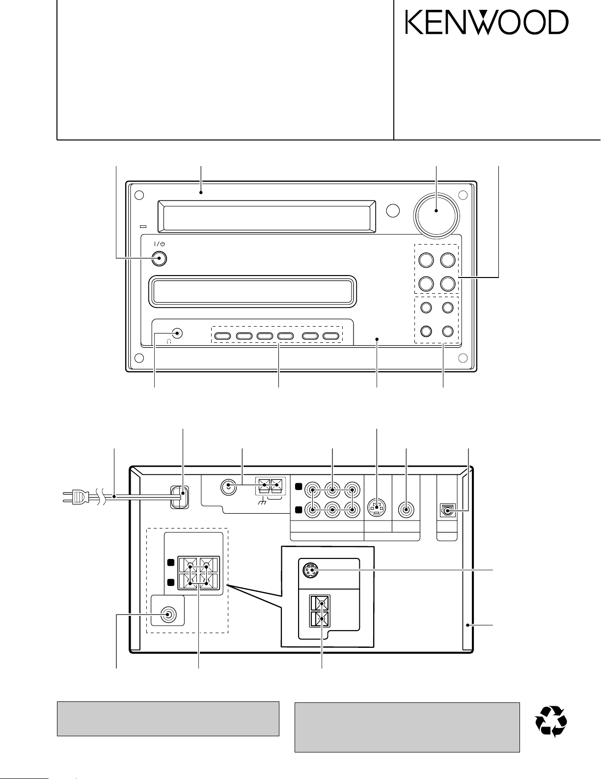
MICRO HiFi COMPONENT SYSTEM
VOLUME/
MULTI CONTROL
STANDBY
/TIMER
DVD/CD 6TUNER/
BAND
41¢
¡
DVD/CD 0STOP
7
TUNING MODE
AUX
PHONES
SOUND MODE SET/DEMO REPEAT RANDOM
P.CALL
R
L
GND
FM75 Ω
AM
SUB WOOFER
PRE OUT
ANTENNA
AUDIO
AUXINCD - R
OUT
S-VIDEO VIDEO
VIDEO OUT
OPTICAL
DIGITAL OUT
PCM/BIT
STREAM
CD - R
IN
+
-
R
L
SPEAKERS
( 6
-16 Ω
)
RD-DV5
TO OPM-DV7
SATELLITE
SPEAKER
SUB
WOOFER
+
-
( 8
-16
)
Ω
RD-DV7
RD-DV5-S/DV7-L
RD-DV5MD-S
SERVICE MANUAL
Knob *
(K29-)
Phone jack
(E11-0941-05)
AC power cord bushing
(J42-0083-05)
AC power cord *
(E30-)
Panel *
(A60-)
Knob
(K29-7999-03)
Tuner assy *
(W02-)
Dressing panel *
(A21-)
Cylindrical receptacle
(E56-0032-05)
Pin jack *
(E63-)
© 2001-9 PRINTED IN KOREA
B51-5754-00 (K/K) 2345
Knob
(K29-8001-14)
Knob *
(K29-)
Pin jack
(E63-1220-05)
Knob
(K29-7997-03)
Oscillating module
(W02-2803-05)
Pin jack
(E63-1162-05)
In compliance with Federal Regulations, following are reproduction of labels on, or inside the product relating to laser
product safety.
Lock terminal board
(E70-0148-05)
Lock terminal board
(E70-0146-05)
KENWOOD-Corp. certifies this equipment conforms to DHHS
Regulations No.21 CFR 1040. 10, Chapter 1, subchapter J.
* Refer to parts list on page 48 .
Illustration is RD-DV5-S/DV7-L.
DANGER : Laser radiation when open and interlock defeated.
AVOID DIRECT EXPOSURE TO BEAM.
Cylindrical receptacle
(E56-0038-05)
Metallic cabinet
(A01-3820-11)
Page 2
RD-DV5-S/DV7-L/DV5MD-S
The marking this product has been
classified as Class 1. It means that
there is no danger of hazardous radiation outside the product.
Location: Back panel
CLASS 1
LASER PRODUCT
The marking of products using lasers
(For countries other than U.S.A., U.S.-Military and Canada)
Inside this laser product, a laser diode classified as Class 2 laser radiation is contained as alerted by
the internal caution label shown
above. Do not stare into beam.
Location: DVD laser pick-up unit
cover inside this product
CAUTION
VISIBLE LASER RADIATION
WHEN OPEN. DO NOT
STARE INTO BEAM.
Inside this laser product, a laser diode classified as Class 3B laser radiation is contained as alerted by
the internal caution label shown
above. Avoid exposure to laser
beams.
Location: MD laser pick-up unit
cover inside this product
CAUTION
VISIBLE LASER
RADIATION WHEN OPEN.
AVOID EXPOSURE TO BEAM.
Operation to reset
The microcomputer may fall into malfunction (impossibility to
operate, erroneous display, etc.) when the power cord is unplugged while unit is ON or due to an external factor. In this
case, execute the following procedure to reset the microcomputer and return it to normal condition.
Unplug the power cord from the power outlet
then, while holding the STOP 7 /TUNING MODE
key depressed, plug the power cord again.
÷ Please note that resetting the microcomputer clears
the contents stored in and it returns to condition
when it left the factory.
REMOTE MODEL
MAIN UNIT DESTINATION
CONTOROLLER NAME
A70-1521-05 RC-M0513 RD-DV5MD-S M
A70-1522-05 RC-F0504E RD-DV5-S TE
A70-1524-05 RC-F0505 RD-DV7-L M2X2V2
A70-1525-05 RC-F0505E RD-DV7-L T2E2
SYSTEM MAIN UNIT DESTINATION SPEAKER SP CORD PARTS No.
HM-DV6MD RD-DV5MD-S M LS-DV6-S E30-5500-05
HM-DV5 RD-DV5-S TE LS-DV5-S E30-5941-04
HM-DV6 RD-DV5-S E LS-DV6-S E30-5500-05
HM-DV7 RD-DV7-L T2E2M2X2V2 OPM-DV7-L E30-5943-08
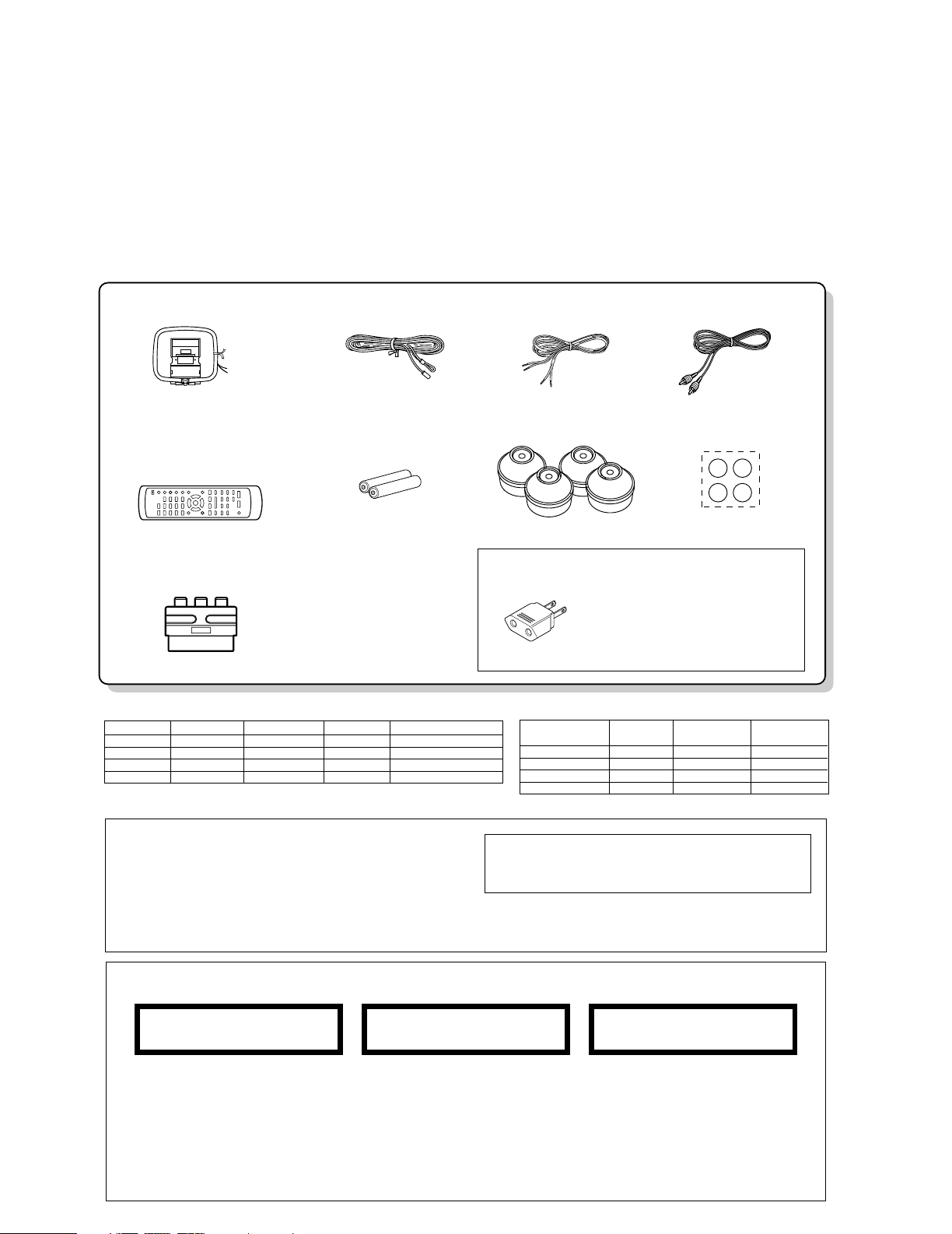
Remote controller
System configurations
FM indoor antenna (1)
(T90-0855-05)
AM loop antenna(1)
(T90-0852-05)
Video cord(1)
(E30-7226-05)
Speaker cord(2)
Remote control unit(1)
(A70-1521-05): M
(A70-1522-05): TE
(A70-1524-05): M2X2V2
(A70-1525-05): T2E2
Batteries (R6/AA)(2)
SCAT plug adaptor for TV(1)
(For EUROPE and U.K.)
(E69-0012-05)
Cushion for satellite speaker(4)
(W01-1178-08)
Feet for speaker(4)
(J02-0034-08)
AC Plug Adaptor (1)
(E03-0115-05)
Use to adapt the plug on the
power cord to the shape of the
wall outlet.
(Accessory only for regions where
use is necessary.)
CONTENTS / ACCESSORIES / CAUTIONS
Contents
CONTENTS / ACCESSORIES / CAUTIONS............. 2
DISASSEMBLY FOR REPAIR....................................3
BLOCK DIAGRAM ......................................................6
CIRCUIT DESCRIPTION ............................................7
ADJUSTMENT ..........................................................14
WIRING DIAGRAM ...................................................15
Accessories
PARTS DESCRIPTIONS ..........................................16
PC BOARD .............................................................. 17
SCHEMATIC DIAGRAM .......................................... 25
EXPLODED VIEW ....................................................45
PARTS LIST..............................................................48
SPECIFICATIONS ......................................Back cover
Cautions
2
Page 3
DISASSEMBLY FOR REPAIR
5cm以上
(HEX DRIVER)
2mm
2mm
GEAR
DVD(CD) MECHA
GEAR
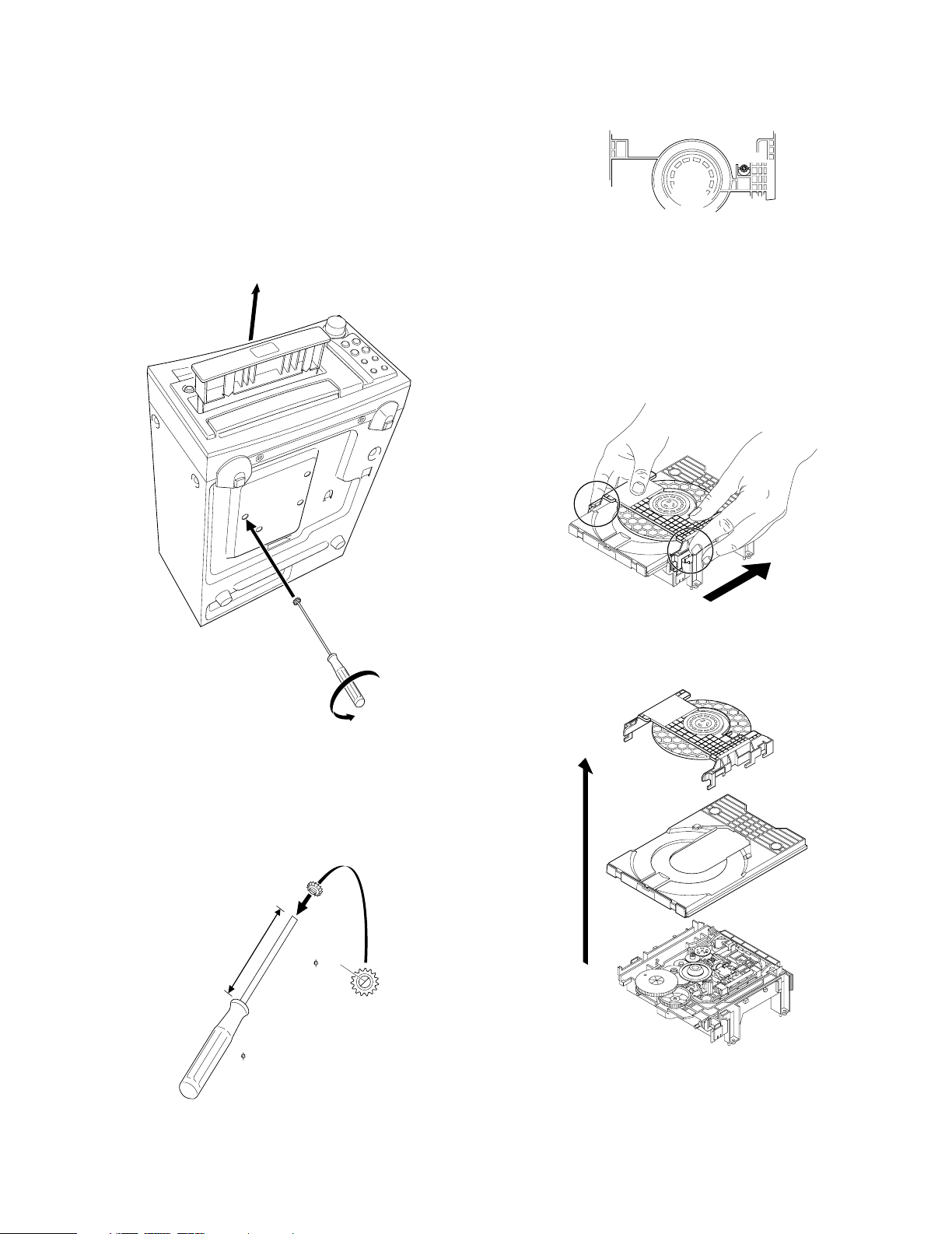
How to open the tray if it does not come out.
1. Insert a jig and turn it fully ccw in the drawing through the
hole on the loading chassis bottom.
2. Pull out the tray frontward by hand when it comes just out.
RD-DV5-S/DV7-L/DV5MD-S
Fig. 3
How to open the tray and a clamper.
1. Pull out the tray slightly frontward by hand.
(Refer to Fig .1)
2. Remove the tray.
3. Remove the clamper in the arrow direction.
Fig .1
* How to make a jig
Insert a hex wrench to a hole of gear (W05-0881-00) in
the drawing below.
If you lost the gear use it which located on DVD mechanism in the drawing (Fig .3).
Fig. 4
4. Remove the tray and clamper upward.
Fig. 5
Fig. 2
3
Page 4
RD-DV5-S/DV7-L/DV5MD-S
TRAVERSE
GEAR A
GEAR B
CUT
MECHA.
CHASSIS
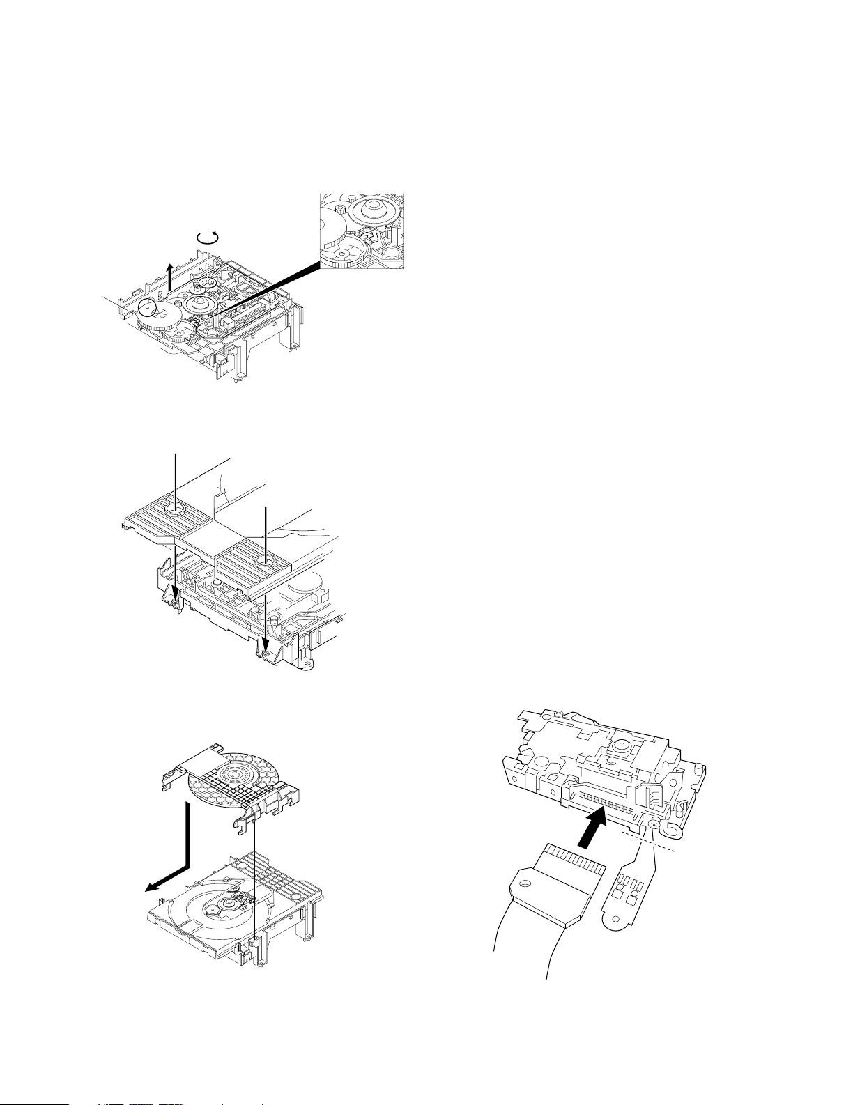
DISASSEMBLY FOR REPAIR
How to attach the tray and the clamper.
1. Turn the traverse gear A in the direction of the arrow in
the drawing so that the traverse
unit will reach the highest position.
Fig. 6
2. Attach the tray in the arrow direction.
Fig. 7
Assembling and Disassembling the Optical Pickup
The optical pickup can be damaged by static electricity
from your body.
Be sure to take static electricity countermeasures when
working around the optical pickup.
Handling the Optical Pickup
1. The optical pickup is an extremely high-precision mechanism. Do not subject it to strong damage.
2. Testers cannot be used to check the laser diode of the
optical pickup. The power supply in side the tester can
easily damage the laser diode.
3. Take care when handling the flexible cable because
excessive force can cause it to break.
4. To preserve the quality of the optical pickup replacement
parts during transport and installation, the terminals of the
laser diode are short-circuited. After replacing the parts,
use the proper procedure to return the laser diode to its
original condition.
Static Electricity Countermeasures
The laser diode inside the traverse unit (optical pickup )
can be damaged by static electricity from your body. Be
sure to take static electricity countermeasures when working around the optical pickup.
Static Electricity Countermeasure Methods
1. Ground yourself
Use an anti-static wrist strap to discharge static electricity
from your body.
2. Ground the workbench
Lay a conductive material (sheet) or steel sheet on the
surface where the traverse unit (optical pickup)is to be
placed, then ground the sheet.
Assembling the Optical Pickup
1. Insert a flexible cable in the arrow direction in the drawing.
2. Cut the flexible cable.
3. Attach the clamper in the arrow direction.
Fig. 8
4
Page 5
RD-DV5-S/DV7-L/DV5MD-S
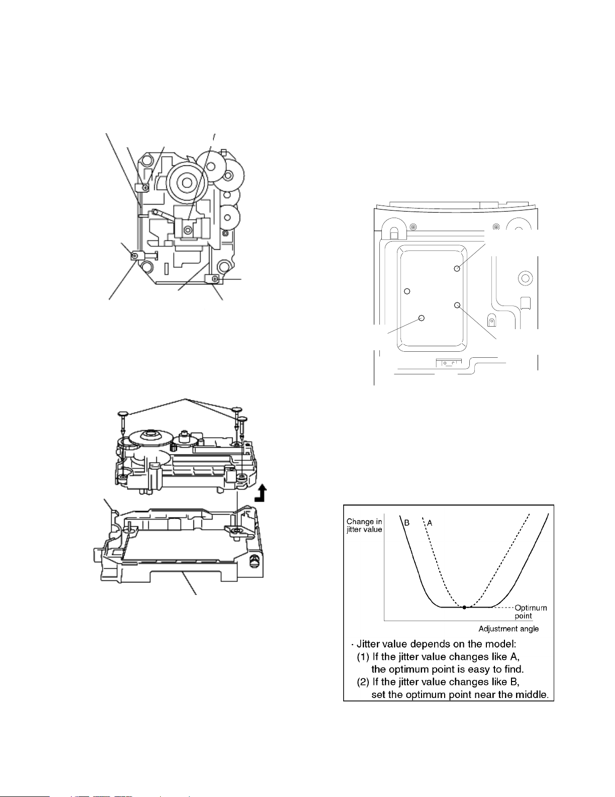
TILT ADJ.
SCREW 1
BOTTOM VIEW
TILT ADJ.
SCREW 2
TANGENTIAL
ADJ.SCREW
FRONT
DISASSEMBLY FOR REPAIR
Disassembling the Optical Pickup
1. Remove screws.
2. Remove spring holder and spring.
3. Pull out the drive-shaft and guide shaft.
GUIDE SHAFT
SCREW
SCREW
SPRING HOLDER SPRING HOLDER
SPRING HOLDER
DRIVE SHFT
OPTICAL PICKUP
SCREW
Disassembling the Middle Chassis
1. Remove 3 push rivets.
2. Remove the hooks.
3. Lift the traverse unit upward to remove the middle chassis.
HOOKS
PUSH RIVETS
*6. Play DVD disc last chapter (outer periphery).
7. Adjust to the minimum jitter value.
(Tilt adjustment screw1)
*8. Play DVD disc last chapter (outer periphery).
9. Adjust to the minimum jitter value.
(Tilt adjustment screw2)
10. Repeat adjusting tilt adjustment screws 1 and 2 alternately, two or three times.
* Press "SKIP UP/SKIP DOWN" keys for Tno. up or
down.
Do item 5~10 from the bottom of the main unit using a
hex wrench.
1-2 Point
1. First of all adjust tangential adjustment then adjust tilt
adjustment.
2. To get optimum point, repeat item 1 adjustment alternately, two or three times.
3. Finally, adjust the tilt adjustment.
MIDDLE CHASSIS
1. Optical pickup Tilt Adjustment
1-1 Adjustment
1. Insert the AC power plug to AC wall outlet with pressing the DVD/CD play key.
(The tray opens automatically)
2. Load a DVD disc and press DVD/CD play key.
3. Press "SOUND" key.
(Jitter value is displayed.)
JITT XXX % XXX is present jitter value
*4. Play DVD disc first chapter (inner periphery).
5. Adjust to the minimum jitter value.
(Tangential adjustment screw)
1-3 Check condition after adjustment
1. Play the disc to make sure there is no picture degradation in the inner, middle and outer peripheries, and no
audio skipping.
2. Lock the adjustment screw in position using screw lock.
5
Page 6
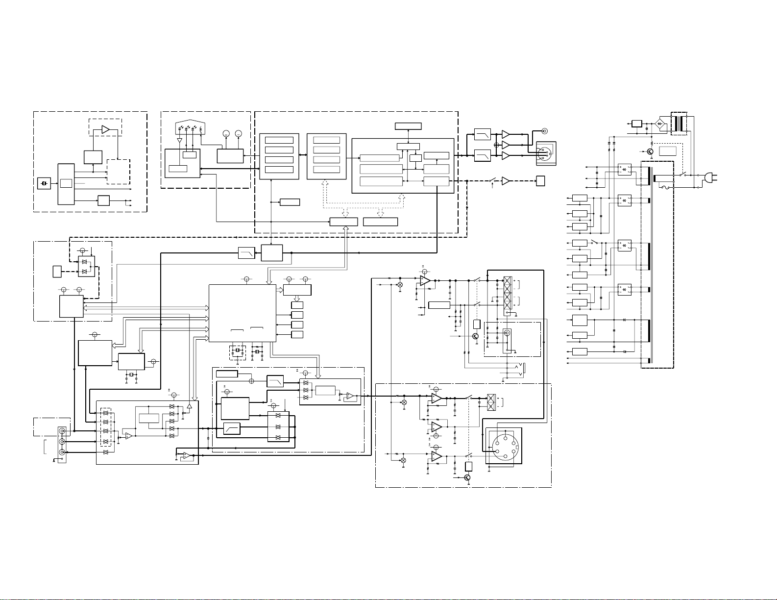
TRACKING
FOCUS
DVD
CD
16.9344MHz33.8688MHz
768Fs
512Fs
27MHz
384Fs
13.5MHz
ODC
ADSC
AUDIO
DAC
C
COMP
Y
+3.3V
D. IN/CD
MD D+5V MD A+3.15V
MD H+5V
ANALOG REC
PLAY
AUDIO DAC
u+5V
DVD u-COM
TUNER
RDS
XIN
L,Rch-VR
XCIN
XOUT
XCOUT
C,SWch-VR
(10MHz)
(32.768kHz)
CLOCK
COLCK
TIMMER
MAIN
-30V +5V
Lch-OUT
Rch-OUT
+9V
DET-OUT
D5V
+5V
4.332MHz
7.5V
8V
8V
C12,C34 OFF
8V
4ch
2ch
HP
C,SWch
L,Rch
B
B
MUTE
B
B
D. OUT SW
A CLASS
CONT
TH LEVEL
L,R RELAY
SP LEVEL
Cch
C,SW RELAY
SWch
+
+5.1V
POWER
RELAY
+B
++
-B
AMP
GND
AMP
+
MD HEAD.
MD
OTHER
DIGITAL
ANALOG
++
E. VOL
VIDEO
TUNER
E. VOL
DVD
+
DVD
FAN
CONT.
DVD
MOTOR
+
DRIVER
FL
+
FL
TUNER
DVD u-COM
RF AMP
AN8708
FRONT-END
PROCESSOR
EEPROM
IC201
PLL/DSL
HF
SERVO CONT
CIRC/DAC
SERVO CONTROLLER
ADVANCED DISC
AN8499
AN8708
TRAVERSE/
DRIVER
M
APC
PICKUP
LOADINGMSPDL
IC1
ECC
MN67706
MN103S13B
ATAPI
ROM DEC
IC101
OPTICAL DISC
CONTROLLER
4MDRAM
8M FLASH ROM
IC207
ADDRESS DATA BUS
AV DECODER
IC301
AC3,LPCM,MP3
AUDIO DECODER PCM &
SPDIF
SDRAM I/F
64M SDRAM
CSS DISSCRAMBLE
VIDEO DECODER
MPEG,SUB PICTURE
VIDEO DAC
ENCODER
NTSC/PAL
OSD
MN677533MP
IC401
AVDEC
IC207
1/2
SM8703AV
PLL
X202
27MHz
IC211
IC210
IC213
1/2
DVD u-COM
IC201
GENERATOR
CLOCK
S OUT
COMPOSIT
6.75MHz
6.75MHz
X29,J2
OUT
OPT OUT
X29,A2
X29,J1
X29,IC7
VIDEO
AMP
X29,IC5
X29,A1
OPT IN
MD MECHA
MDM-15AL
X29,IC5
96k 24bit
2ch DAC
X29,IC17
PCM1748
60kHz
M30624MGA356F
MAIN u-COM
X29,IC15
FL DRIVER
M66005-001FP
FL
LED
KEY
REM
X14,IC1
X14,ED1
TUNER PACK
RDS IC
X29,IC16
IN
OUT
VIDEO2
IN
VIDEO1
(AUDIO)
X29,J3
X29,IC1
M62492FP
TONE
EX. BASS
INPUT
MAIN
REC
OUT
VOL.
VOL.
ATT.
PSS-3200
A3
OTHER ch
IC3
IC4
TONE
EX. BASS
C,SW VR
PROCESSOR
STEREO AUDIO
DIGITAL CONTROLLED
TC9215AP
PAROUND
PROCESSOR
MODULE
AUDIO SEL.
POINT SOURCE
X07,J3
SATELLITE
SPEAKER
E. VOLUME
Rch
Lch
J1
S. W. PRE-OUT
X14,J1
H. P.
K2
OTHER ch
AMP
X07,IC1
Q1,2
MUTE
J4
SWch
K3
IC2
AMP
Q3
MUTE
AMP
MUTE
Q5
AMP
IC3
K3
+5V
IC11
u-COM
R/C SENSOR
R/C VDD
D10
X07,
Q302
X07,D1
S1
S2
X07,D4
+3.15V
+5V
X07,IC14
X29,IC12
POWER
RELAY
X07,D3
-8V
+8V
X29,IC11
X29,IC14
+9V
X29,IC10
S3
S4
X07,D2
X07,Q311
+3.3V
X07,IC13
+5V
X07,Q13
FAN
DRIVE
S5
X07,IC12
+9V
-30V
X07,Q14
S6
K1
PICKUP UNIT(X35-2302-72)
CLK SYSTEM
(X35-2302-72)
RD-DV5MD
ONLY
E/T ONLY
RD-DV5/DV7
ONLY
RD-DV7
ONLY
RD-DV5/
ONLY
RD-DV7
ONLY
DV5MD
RD-DV5MD/DV5/DV7
6
RD-DV5-S/DV7-L/DV5MD-S
BLOCK DIAGRAM
Page 7
RD-DV5-S/DV7-L/DV5MD-S
CIRCUIT DESCRIPTION
1. Initializing
1-1 Initialization Method
• While pressing the [STOP] key, turn the AC on.
1-2 Initialization Operation
• During the initial operation, the display shows "INITIALIZE"and after that it will be returned to standby condition.
• If any mechanisms error occurred, the error indication is
displayed as "ERR" on the display.
1-3 Mechanism Initializations
DVD Mechanism
• If a mechanism error occurred, the error indication is displayed as "DVD ERR" on the display.
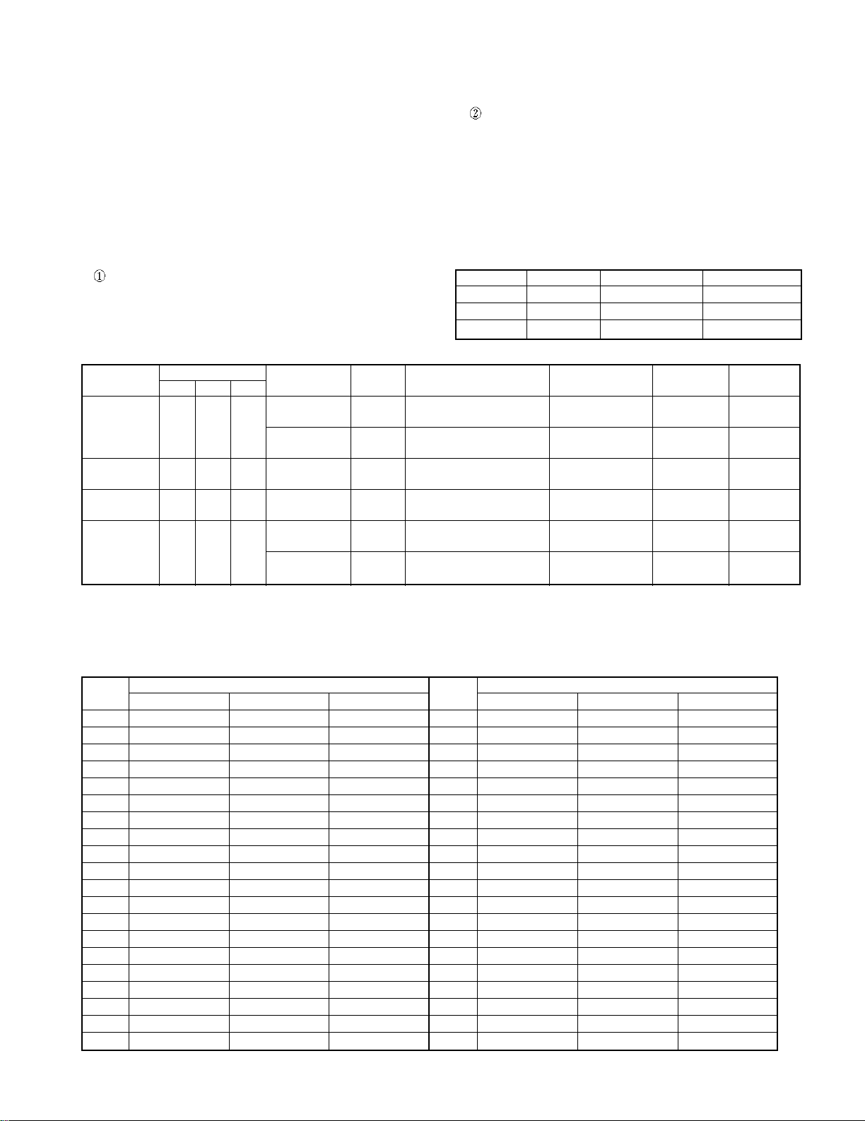
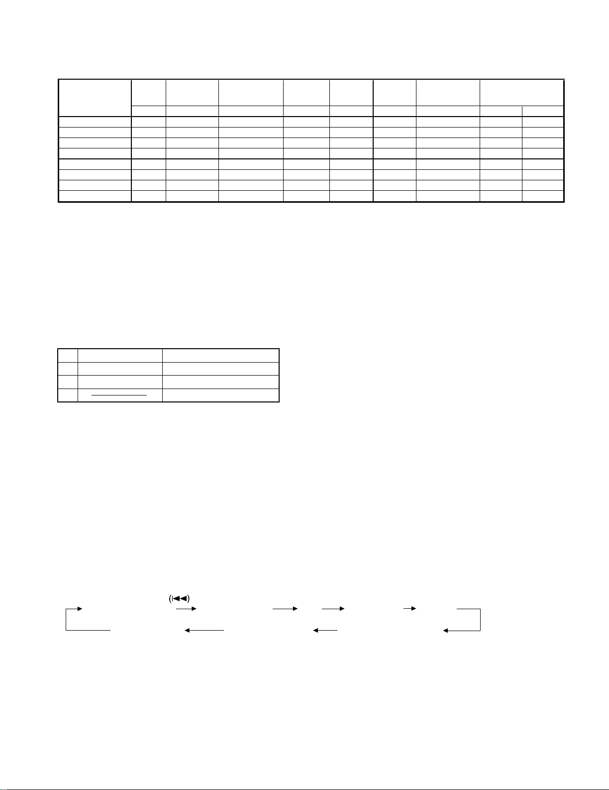
2-2Tuner Destination
Destination Destination SW u-COM
2 1 0 Destination Range
K2
M011
E1
X001E1
E/T (RDS) 1 0 1 E3
K2
V111
E1
BAND
FM 87.5MHz~108.0MHz 100kHz +10.7MHz 25kHz
AM 530kHz~1610kHz 10kHz +450kHz 10kHz
FM 87.5MHz~108.0MHz 50kHz +10.7MHz 25kHz
AM 531kHz~1602kHz 9kHz +450kHz 9kHz
FM 87.5MHz~108.0MHz 50kHz +10.7MHz 25kHz
AM 531kHz~1602kHz 9kHz +450kHz 9kHz
FM 87.5MHz~108.0MHz 50kHz +10.7MHz 25kHz
AM 531kHz~1602kHz 9kHz +450kHz 9kHz
FM 87.5MHz~108.0MHz 100kHz +10.7MHz 25kHz
AM 530kHz~1610kHz 10kHz +450kHz 10kHz
FM 87.5MHz~108.0MHz 50kHz +10.7MHz 25kHz
AM 531kHz~1602kHz 9kHz +450kHz 9kHz
MD Mechanism
• If a mechanism error occurred, the error indication is displayed as "MD ERR" on the display.
• The disc will be unloaded from MD mechanism automatically, if a disc is its in.
2. Discrimination of the Model and Destination
for Tuner
2-1 Discrimination of the Model
Models Destination Destination SW3 Destination SW4
RD-DV5MD M 0 0
RD-DV5 E/T 0 0
RD-DV7 T/E1/M1/X/V 1 1
Receiving Frequency
Channel Space IF RF
✽ Destination SW
SW0 : (78)Pin SW1 : (77)Pin SW2 : (76)Pin SW3 : (75)Pin SW4 : (74)Pin
( ) Pin No. of System Microcomputer : X29,IC15
3. Tuner Preset Frequency
P.CH
1 FM 87.50MHz FM 87.50MHz FM 87.50MHz 21 AM 530kHz AM 530kHz AM 531kHz
2 FM 108.0MHz FM 108.0MHz FM 108.0MHz 22 FM 87.50MHz FM 87.50MHz FM 87.50MHz
3 FM 98.00MHz FM 98.00MHz FM 98.00MHz 23 FM 87.50MHz FM 87.50MHz FM 87.50MHz
4 FM 108.0MHz FM 108.0MHz FM 89.10MHz 24 FM 87.50MHz FM 87.50MHz FM 87.50MHz
5 FM 90.00MHz FM 90.00MHz FM 90.00MHz 25 FM 87.50MHz FM 87.50MHz FM 87.50MHz
6 FM 87.50MHz FM 87.50MHz FM 87.50MHz 26 FM 87.50MHz FM 87.50MHz FM 87.50MHz
7 FM 87.50MHz FM 87.50MHz FM 87.50MHz 27 FM 87.50MHz FM 87.50MHz FM 87.50MHz
8 AM 530kHz AM 530kHz AM 531kHz 28 FM 87.50MHz FM 87.50MHz FM 87.50MHz
9 AM 1700kHz AM 1610kHz AM 1602kHz 29 FM 87.50MHz FM 87.50MHz FM 87.50MHz
10 AM 1000kHz AM 1000kHz AM 999kHz 30 FM 106.0MHz FM 106.0MHz FM 106.0MHz
11 AM 530kHz AM 630kHz AM 531kHz 31 FM 87.50MHz FM 87.50MHz FM 87.50MHz
12 AM 1440kHz AM 1440kHz AM 1440kHz 32 FM 87.50MHz FM 87.50MHz FM 87.50MHz
13 FM 106.0MHz FM 106.0MHz FM 106.0MHz 33 FM 87.50MHz FM 87.50MHz FM 87.50MHz
14 AM 530kHz AM 530kHz AM 531kHz 34 FM 87.50MHz FM 87.50MHz FM 87.50MHz
15 FM 87.50MHz FM 87.50MHz FM 87.50MHz 35 FM 87.50MHz FM 87.50MHz FM 87.50MHz
16 FM 98.00MHz FM 98.00MHz FM 98.00MHz 36 FM 87.50MHz FM 87.50MHz FM 87.50MHz
17 FM 98.50MHz FM 98.50MHz FM 98.50MHz 37 FM 87.50MHz FM 87.50MHz FM 87.50MHz
18 FM 87.50MHz FM 87.50MHz FM 87.50MHz 38 FM 87.50MHz FM 87.50MHz FM 87.50MHz
19 AM 990kHz AM 990kHz AM 990kHz 39 FM 108.0MHz FM 108.0MHz FM 108.0MHz
20 FM 97.40MHz FM 97.40MHz FM 97.70MHz 40 AM 1000kHz AM 1000kHz AM 945kHz
K1 K2 E1/E3
Frequency Frequency
P.CH
K1 K2 E1/E3
7
Page 8
RD-DV5-S/DV7-L/DV5MD-S
CIRCUIT DESCRIPTION
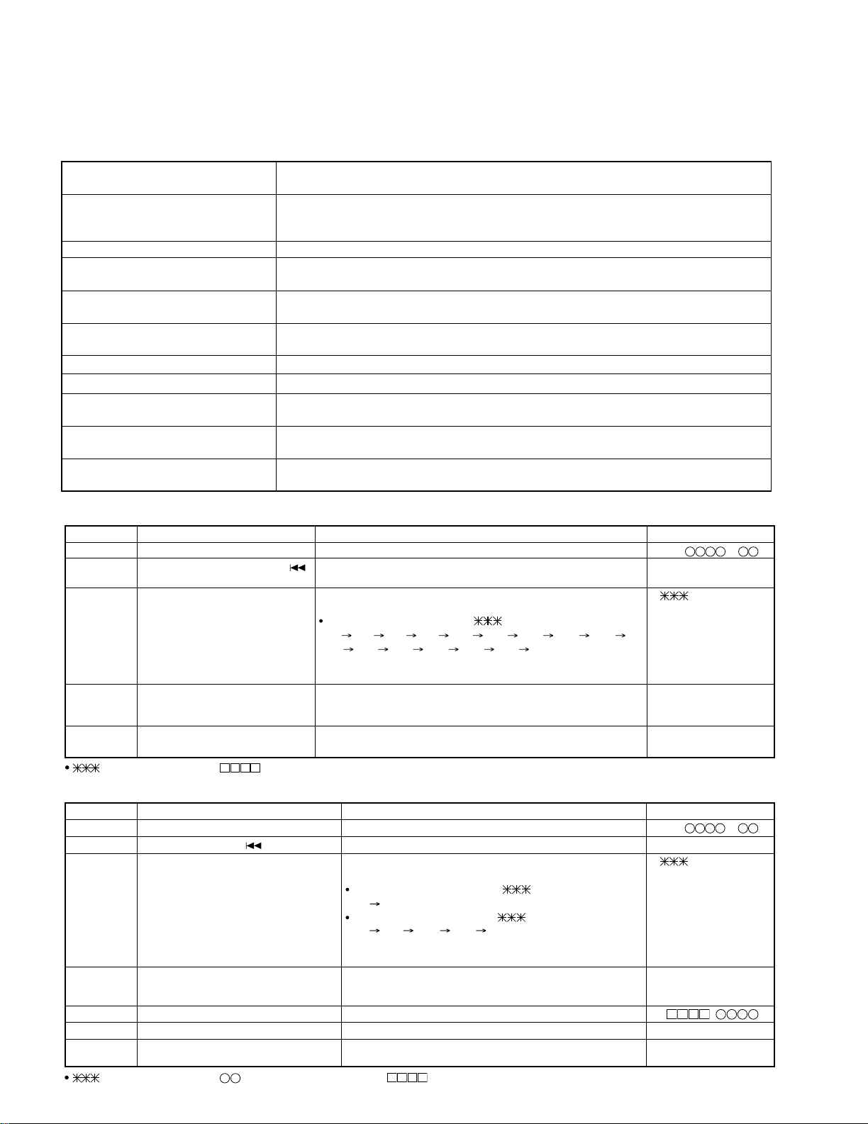
4. Test Mode
4-1 Setting method of the Test Mode
TEST MODE KEY SETTING
DVD TEST MODE DVD PLAY/PAUSE
MD TEST MODE MD PLAY/PAUSE Insert the AC cord to
MD MECHA. ADJ. MODE MD REC AC wall outlet with
FCT & SUB CLOCK SET/DEMO pressing the left key.
OSC DIAGNOSIS
4-2 Cancel of the test mode
• By turning the AC off, the system is initialized and the
test mode is canceled.
• Cancel the test mode only if the power switch is turned
off.
4-3 Contents of the Test Mode
• The muting during mode selection is not controlled in
the test mode.
• During the test mode, it can be operated in a special
manner that is different from an ordinary operation by
using the keys on the main body, specifically as shown
in the following tables.
4-4 FCT(Factory) and Sub clock OSC Diagnosis
Mode
4-4-1 Sub clock OSC Diagnosis Mode
The oscillation diagnosis (existence of oscillation and
measurement of period) of a sub clock is performed
before the test mode is entered. If the diagnosis result
is OK, the system enters the test mode.
If the diagnosis result is NG, the oscillation of the sub
clock is diagnosed again. If the result is OK, the system
enters the test mode. If the diagnosis result is continuously NG 5 times, the system stops with "ERR1"and
"ERR2"displayed.
4-4-2 Operation in the Test Mode
KEY LCD OPERATION
REPEAT OK or
✽✽✽✽ ERROR
Ex : ADSC ERROR
(Advanced Digital Servo Controller) ••• X35, IC1
✽✽✽✽ ERROR
Self diagnosis mode
(Refer to servo error code)
4-5 DVD Test Mode
KEYS DISPLAY OPERATION
DVD PLAY/PAUSE
(Cyclically changed the mode play Usual Indication Disc playback
and pause by pressing the key.)
STOP(in playback mode) DVD TEST Stop the playback and return to first step of this test mode
STOP(in stop mode) Region code Indicated the region code
SKIP UP/SKIP DOWN Usual Indication Skip up/down operation in the DVD playback.
SOUND J ITT ✽✽✽ % Shows jitter value (binary values vs time deviation of PLL clock).
MD REC Usual Indication FF Operation (triple speed)
REC MODE Usual Indication FB Operation (triple speed)
4-6 MD Test Mode
KEYS DISPLAY OPERATION
MD PLAY/PAUSE Usual Indication MD playback/pause
STOP MD TEST Stop the MD operation.
SKIP UP/DOWN Usual Indication MD track up/down
REC MODE Usual Indication Hi-speed O.T.E.(DVD î MD) operation in the stop mode.
Start the MD recording with LP4 mode.
MD REC Usual Indication Start analog recording (DVD î MD).
MODE Usual Indication Start digital recording (D. AUX î MD).
SET ALL ERASE Stop the MD operation , and start operation of ALL- ERASE if disc is recordable.
4-7 MD Mecha. Adjustment
1. Preparation for Adjustment You have to carry out the following test mode items if replace MD mechanism, pickup, head and pc board.
1-1 Procedure
1. Short-circuit #4(vss) and #7(wp) of IC1402(EEPROM).
2. Set the unit to test mode and carry out the every adjustment in test mode.
3. Stop the test mode by pressing the STOP key for 3 secs
4. Remove the short circuit of IC1402. Carry out reset start.
8
Page 9
RD-DV5-S/DV7-L/DV5MD-S
TEMP EEPROM
✽ EEPROM
AUTO
AUTO
AUTO
✽ EEPROM ✽ ✽ Operation
Standard Set
data write
Pre
adjustment
AFB
data write check
Repair (replace)
Set value check adjustment adjustment
TEMP EEPROM SET Cancel Test Mode AUTO YOBI AUTO ADJ AUTO AFB Cancel Test Mode TEST PLAY TEST REC
Pickup - 12345678
Recording head - - - - - - - - 1
Mechanism - 12345678
PCB parts 12 3 4 56 7 89
MD microprocessor - 12--- - 34
MD LSI - - - 123 4 56
RF IC 12 3 4 56 7 89
EEPROM 12 3 4 56 7 89
1-2 Test disc
Type Test disc
1 High reflection disc TGYS1 (SONY)
2 Low reflection disc Recording minidisc
3 Head Adjusting transparent
Entering the specific mode
Whenever the button SKIP DOWN
is pressed, the mode is changed.
AUTO
(AUT YOBI) (AUTO AJST) (AUT AFB) (RST YOBI) (RESULT)
(MNU YOBI)(EEPROM SET) (MNU AJST)
pre-adjustment AUTO adjustment RESULT SUB RESULT
EEPROM setting MANUAL adjustment MANUAL pre-adjustment
AUT
CIRCUIT DESCRIPTION
note: figures order of steps." –" no need.
* Result of EEPROM
OK_EEPROM Write the data of setting values and AUTO-pre adjustment perfectly.
WR_EEPROM Write the data of setting values perfectly however not write AUTO pre-adjustment.
Carry out AUTO pre-adjustment and write data to EEPROM.
NG_EEPROM Not write the data of setting values.
Check the connection of MD microprocessor and EEPROM.
** Carry out the TEST-PLAY , TEST-REC and C1 error in test mode after AUTO_ADJ and AUTO_AFB.
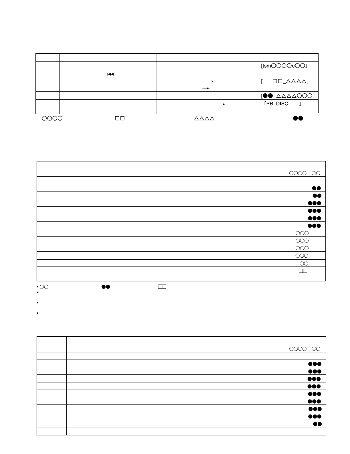
2. Test Mode
1. Holding down the MD rec button and turn the power on. (State A)
2. To enter the test mode stop state(State B), press the STOP button.
3. Load the playback disc 1(high reflection disc) or recording disc 2(low reflection disc).
A MECHA TEST
B tsm
C LOADING
D AUTO AJST
ó (Press STOP key)
‡‡‡‡e‡‡
ó (MD DISC LOAD IN)
ó
---- TEST MODE STOP STATE
(When the STOP button is pressed in the D state, the indication B state is
restored.
To restore D state again, press the SKIP DOWN key once.
represents version of MD microcomputer
‡‡
9
Page 10
RD-DV5-S/DV7-L/DV5MD-S
• Canceling the test mode
When the POWER button is pressed, the test mode is canceled, and the POWER OFF state is set.
• Test Mode
1. AUTO pre-adjustment mode • Automatic pre-adjustment is performed. (After adjustment the grating adjustment mode is set.)
• The adjustment value is output with the aid of system controller interface.
2. AUTO adjustment mode • Automatic adjustment is performed.
• The adjustment value is output with the aid of system controller interface.
• Continuous playback is performed. (Error rate indication, jump test)
4. RESULT sub-mode • The measurement value, set value and calculated value are indicated.
• The set value is changed manually (in servo OFF state).
3. AFB adjustment • Focus Balance adjustment is performed auto matically.
5. RESULT mode (final adjustment) • The set value (after calculation) is indicated.
• The set value is changed manually (in servo OFF state).
6. MANUAL pre-adjustment mode • RF side manual adjustment is performed.
• Focus and tracking signal offset setting is performed.
7. MANUAL adjustment mode • Focus and tracking signal ATT manual adjustment is performed.
8. EEPROM setting mode • EEPROM setting
9. TEST-PLAY mode • Continuous playback from the specified address is performed.
• C1 error rate measurement.
10. TEST-REC mode • Continuous recording from the specified address is performed.
• Change of record laser output (servo gain is also changed according to laser output)
11. EJECT mode • TEMP
• Laser power adjustment
setting (of EEPROM setting)
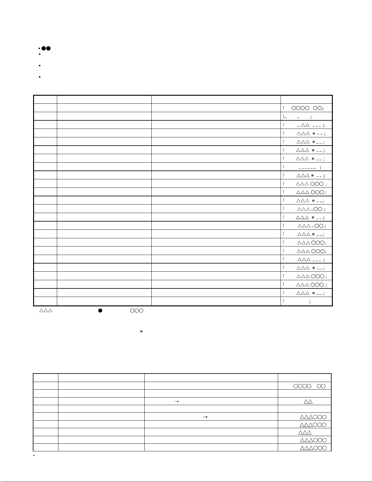
1. AUTO pre-adjustment mode (Low reflection disc only)
Step No.
Setting Method
Remarks Display
Step 1 Test mode STOP state [ t s m e ]
Step 2 Press once the SKIP DOWN( )
button eight times.
AUTO pre-adjustment menu [ AUT_ YOBI_ _ _ ]
Step 3 Press once the MD PLAY button. The slide moves to the innermost periphery, and automatic [ : _ _ _ _ _ _ _ ]
pre-adjustment is started.
During automatic adjustment changes as follows.
HAo
RFg SAg SBg PTG PCH GTG GCH RCG
SEG RFG SAG HAO HEO TCO LAO
End of adjustment If adjustment is OK, Step 4.
If adjustment is NG, Step 5.
Step 4 Grating adjustment, [ _ C O M P L E T E _ ]
adjustment value output
Press once the MD STOP button. STEP 2
Step 5 Adjustment value output [ AUT YOBI ]
Press once the MD STOP button. STEP 2 AUTO pre-adjustment menu
: Adjustment name, : Address
2. AUTO adjustment mode
Step No.
Setting Method
Remarks Display
Step 1 Test mode STOP state [ t s m e ]
Step 2
Press the SKIP DOWN( ) button one times.
AUTO adjustment menu [ A U T O _ A J S T _ ]
Step 3 Press once the MD PLAY button. The slide moves to the innermost periphery, and automatic [ : _ _ _ _ _ _ ]
adjustment is started.
In case of high reflection disc changes as follows.
PEG
HAG
In case of low reflection disc changes as follows.
PEG LAG GCG GEG LAG
End of adjustment If adjustment is OK, Step 4.
If adjustment is NG, Step 7.
Step 4 Adjustment value output
[ C O M P L E T E ]
Press the MD PLAY button. STEP 5
Press the MD STOP button. STEP 2
Step 5
Continuous playback (groove section)
[ a c ]
Step 6
Press the MD STOP button. STEP 2 AUTO adjustment menu
Step 7 Adjustment value output [ C a n ' t _ A D J . ]
Press the MD STOP button. STEP 2 AUTO adjustment menu
: Adjustment name, : Measurement value, : Address
CIRCUIT DESCRIPTION
10
Page 11
RD-DV5-S/DV7-L/DV5MD-S
3. AUTO FAB adjusting mode
Step No. Setting Method Remarks Display
Step 1 Test mode STOP state
Step 2
Press the SKIP DOWN( ) button two times
AUTO FAB adjustment menu [_AUT_AFB_ _]
Step 3 Press the MD PLAY button 1 time
Step 4 Press the MD STOP button AUTO AFB adjustment menu, step 2
Step 5
• : measurement value : AFB value in measurement, : C1 error value in measurement, : AFB
value
• If the STOP button is pressed twice while the AUTO AFB adjustment is displayed, the state is change to the TEST mode
STOP state.
AFB
Step 1 Test mode STOP state [ t s m e ]
Step 2
Press the SKIP DOWN(4) button three times.
RESULT sub-menu [ _ R S T _ Y O B I _ ]
Step 3 Press once the MD PLAY button. Indication of measurement value [ P C H : _ _ _ _ ]
Step 4
Press once the SKIP DOWN(4) button.
Indication of measurement value [ G C H : _ _ _ _ ]
Step 5
Press once the SKIP DOWN(4) button.
Indication of measurement value [ S A G : _ _ _ ]
Step 6
Press once the SKIP DOWN(4) button.
Indication of measurement value [ S B G : _ _ _ ]
Step 7
Press once the SKIP DOWN(4) button.
Indication of measurement value [ S E G : _ _ _ ]
Step 8
Press once the SKIP DOWN(4) button.
Indication of measurement value [ S F G : _ _ _ ]
Step 9
Press once the SKIP DOWN(4) button.
Indication of measurement value [ H A O : _ _ _]
Step 10
Press once the SKIP DOWN(4) button.
Indication of measurement value [ H B O : _ _ _]
Step 11
Press once the SKIP DOWN(4) button.
Indication of measurement value [ H E O : _ _ _]
Step 12
Press once the SKIP DOWN(4) button.
Indication of measurement value [ H F O : _ _ _]
Step 13
Press once the SKIP DOWN(4) button.
Indication of measurement value [ T C O : _ _ _ _]
Step 14
Press once the SKIP DOWN(4) button.
Indication of pre-adjustment not completed (00)/completed (4B) [ A D J : _ _ _ _]
Step 15 Press once the MD STOP button. RESULT sub-menu state [ _ R S T _ Y O B I _ ]
4. RESULT sub-mode
Step No.
Setting Method
Remarks Display
: Measurement value, : Adjustment value, : Other various informations
When the (¡)button in remote controller is pressed while the setting is displayed, the setting increases,
and a new setting is stored in RAM.
When the (1)button in remote controller is pressed while the setting is displayed, the setting increases,
and a new setting is stored in RAM.
When the (¡) or (1)button in remote controller is pressed continously, steps is change by 100ms period.
Step 1 Test mode STOP state [ t s m e ]
Step 2 Press the SKIP DOWN(4) button four times. RESULT menu [ _ R S T U L T _ _ _ ]
Step 3 Press once the MD PLAY button. Indication of set value [ H A G : _ _ _ ]
Step 4
Press once the SKIP DOWN(4) button.
Indication of set value [ H B G : _ _ _ ]
Step 5
Press once the SKIP DOWN(4) button.
Indication of set value [ L A G : _ _ _ ]
Step 6
Press once the SKIP DOWN(4) button.
Indication of set value [ L B G : _ _ _ ]
Step 7
Press once the SKIP DOWN(4) button.
Indication of set value [ P E G : _ _ _ ]
Step 8
Press once the SKIP DOWN(4) button.
Indication of set value [ P F G : _ _ _ ]
Step 9
Press once the SKIP DOWN(4) button.
Indication of set value [ G E G : _ _ _ ]
Step 10
Press once the SKIP DOWN(4) button.
Indication of set value [ G F G : _ _ _ ]
Step 11
Press once the SKIP DOWN(4) button.
Indication of set value [ G C G : _ _ _ _ ]
Step 12 Press once the MD STOP button. RESULT menu state [ _ R E S U L T _ _ _ ]
5. RESULT mode (final adjustment)
Step No.
Setting Method
Remarks Display
CIRCUIT DESCRIPTION
End of automatic adj. step 4
High reflection disc step 5
Message output for 1 sec. AUTO AFB.
Adjustment menu(high reflection disc)
11
Page 12
RD-DV5-S/DV7-L/DV5MD-S
When the (¡)button in remote controller is pressed while the setting is displayed, the setting increases,
and a new setting is stored in RAM.
When the (1)button in remote controller is pressed while the setting is displayed, the setting increases,
and a new setting is stored in RAM.
When the (¡) or (1)button in remote controller is pressed continously, steps is change by 100ms period.
: Measurement value
6. MANUAL auxiliary adjustment mode (only low reflection disc)
Step No. Setting Method Remarks Display
Step 1 Test mode STOP state tsm e
Step 2 Press SKIP DOWN (4) button five times. MANUAL auxiliary adjustment mode
Step 3 Press once the MD PLAY button. Initial setting î Temperature measuring mode TMP :
Step 4 Press SKIP DOWN (4) button. Offset "0" setting î A signal offset tentative measurement HAo :
Step 5 Press SKIP DOWN (4) button. B signal offset tentative measurement HBo :
Step 6 Press SKIP DOWN (4) button. E signal offset tentative measurement HEo :
Step 7 Press SKIP DOWN (4) button. F signal offset tentative measurement HFo :
Step 8 Press SKIP DOWN (4) button. Laser ON LON :
Step 9 Press SKIP DOWN (4) button. ABMAXO measurement ABM :
Step 10 Press SKIP DOWN (4) button. Focus ATT (A signal) tentative setting SAg :
Step 11 Press SKIP DOWN (4) button. Focus ATT (B signal) tentative setting SBg :
Step 12 Press SKIP DOWN (4) button. Pit section LPFEFO measurement PEF :
Step 13 Press SKIP DOWN (4) button. Pit section COUT measurement
Step 14 Press SKIP DOWN (4) button. Groove section LPFEFO measurement
Step 15 Press SKIP DOWN (4) button. Groove section COUT level measurement
Step 16 Press SKIP DOWN (4) button. TCRMIO measurement TCR :
Step 17 Press SKIP DOWN (4) button. Tracking ATT (E signal) setting SEG :
Step 18 Press SKIP DOWN (4) button. Tracking ATT (F signal) setting
Step 19 Press SKIP DOWN (4) button. Indication of tracking EFMIO measurement g MI :
Step 20 Press SKIP DOWN (4) button. LPFABO measurement ABL :
Step 21 Press SKIP DOWN (4) button. Focus ATT (A signal) setting SAG :
Step 22 Press SKIP DOWN (4) button. Focus ATT (B signal) setting SAB :
Step 23 Press SKIP DOWN (4) button.
TCO :
Step 24 Press once the MD STOP button. MNU YOBI state
–
MNU–YOBI
-
• : Measurement value, : Set value : Account value
• When the (⁄) or (!) button in remote controller is pressed while the setting is displayed, the setting increases or decreases,
and a new setting is stored in ROM.
• When the (⁄) or (!) button in remote controller is pressed continuously, steps is change by 100ms period.
If the measurement value is within the OK range, " " appears on the 8th character.
OK range HAO, HB0, HEO, HFO : 0 0 0 h±2 0 0 h
ABM : 1E2h ∼ 9C7h PEF : 20Dh ∼ 785h
GEF : 20Dh ∼ 785h TCR : 030h ∼ 239h
ABL : 1E2h ∼ 9C7h TCO : 00h±20h
Step 1
Test mode STOP state
[ t s m e ]
Step 2
Press the SKIP DOWN(4) button six times.
MANUAL adjustment menu [ _ M N U _ A J S T _ ]
Step 3
Press once the MD PLAY button.
Initial setting Temperature measuring mode [ T M P : _ _ _ _ ]
Step 4
Press once the SKIP DOWN(4) button.
Laser ON [ L O N : _ _ _ _ _ _ ]
Step 5
Press once the SKIP DOWN(4) button.
Innermost periphery move Tracking ATT (E signal) setting [ P E G : ]
Step 6
Press once the SKIP DOWN(4) button.
Tracking ATT (F signal) setting [ P F G : ]
Step 7
Press once the SKIP DOWN(4) button.
Indication of tracking EFMIO measurement [ P M I : _ _ _ ]
Step 8
Press once the SKIP DOWN(4) button.
Focus ATT (A signal) setting [ H A G : ]
Step 9
Press once the SKIP DOWN(4) button.
Focus ATT (B signal) setting [ H B G : ]
7. MANUAL adjustment mode High reflection disc
Step No.
Setting Method
Remarks Display
If the MD STOP button is pressed twice while the MANUAL adjustment menu is displayed, the state is changed to the TEST
mode STOP state.
CIRCUIT DESCRIPTION
12
TCRS signal offset measurement
MNU YOBI
PCH :
GEF :
GCH :
SFG :
-
Page 13
RD-DV5-S/DV7-L/DV5MD-S
8. TEST-PLAY mode
Step 1 Test mode STOP state [ t s m e ]
Step 2
Press once the SKIP UP(¢)button.
Press MD PLAY button.
Press MD PLAY button.
[ T E S T _ P L A Y _ ]
Step 4
Press
Step 3
Press the STOP button.
once the MD PLAY button.
During search the search output is set to "H", and it is
returned to "L" when continuous playback is started.
Continuous playback (groove section)
(Address + C1 error indication)
[a
c ]
Step 5
Press once the MD STOP button. TEST-PLAY menu [ T E S T _ P L A Y _ ]
[ T E S T _ P L A Y _ ]
Step No.
Setting Method
Remarks Display
If the MD STOP button is pressed while the TEST-PLAY menu is displayed, TEST mode STOP state is set.
If the MD PLAY button is pressed while the TEST-PLAY menu is displayed, continuous playback is started from the current pickup position.
: Adress, : Error late
Step 1 Test mode STOP state [ t s m e ]
Step 2
Press the SKIP DOWN(4) button six times.
MANUAL adjustment menu [ _ M N U _ A J S T _ ]
Step 3 Press once the MD PLAY button. Initial setting → Temperature measuring mode [ T M P : _ _ _ _ ]
Step 4
Press once the SKIP DOWN(4) button.
Laser ON [ L O N : _ _ _ _ _ _ ]
Step 5
Press once the SKIP DOWN(4) button.
Innermost periphery move → Tracking ATT (E signal) setting [ P E G : ]
Step 6
Press once the SKIP DOWN(4) button.
Tracking ATT (F signal) setting [ P F G : ]
Step 7
Press once the SKIP DOWN(4) button.
Indication of tracking EFMIO measurement (pit section) [ P M I : _ _ _ ]
Step 8
Press once the SKIP DOWN(4) button.
Focus ATT (A signal) setting [ L A g : ]
Step 9
Press once the SKIP DOWN(4) button.
Focus ATT (B signal) setting [ L B g : ]
Step 10
Press once the SKIP DOWN(4) button.
Outside periphery move → Track closs setting [ G C G : ]
Step 11
Press once the SKIP DOWN(4) button.
Tracking ATT (E signal) setting [ G E G : ]
Step 12
Press once the SKIP DOWN(4) button.
Tracking ATT (F signal) setting [ G F G : ]
Step 13
Press once the SKIP DOWN(4) button.
Indication of tracking EFMIO measurement (groove section) [ G M I : _ _ _ ]
Step 14
Press once the SKIP DOWN(4) button.
Focus ATT (A signal) setting [ L A G : ]
Step 15
Press once the SKIP DOWN(4) button.
Focus ATT (B signal) setting [ L B G : ]
Low reflection disc
Step No.
Setting Method
Remarks Display
If the MD STOP button is pressed twice while the MANUAL adjustment menu is displayed, the state is changed to the TEST mode
STOP state.
SKIP UP(¢)button twice.
9. TEST-REC mode
Step 1 Test mode STOP state [ t s m e ]
Step 2
Press the
[ T E S T _ R E C _ _ ]
Step 3 Press the STOP button.
Step 4 Press
Continuous playback
(groove section)
once the MD PLAY button. During search the search output is set to "H", and it is
returned on "L" when continuous playback is started. (Address
+
C1 error indication) [ a
p w ]
[ a
p w ]
Step 5 Press once the MD STOP button. TEST-REC menu [ T E S T _ R E C _ _ ]
[ T E S T _ R E C _ _ ]
Step No.
Setting Method
Remarks Display
If the MD STOP button is pressed while the TEST-PLAY menu is displayed, TEST mode STOP state is set.
If the MD PLAY button is pressed while the TEST-REC menu is displayed, continuous record is started from the current pickup position.
If
: Measurement value, : Setting value.
the (¡) or (1) button in remote controller is pressed in TEST-REC mode and continuous record mode,
the laser record power changes.
(Servo gain changes also according to the record power.)
: Adress, : Laser power cord
10. EJECT mode
Step 2
Step 1
Test mode
Test mode STOP state
EJECT Eject of MD discstate [ _ _ E J E C T _ _ _ ]
Step 3 Press
SKIP UP(¢)
button. Temperature standard value setting. [ TEMP ]
Step 4 Press STOP button. [ _ _ EJECT _ _ _ _ ]
Step No.
Setting Method
Remarks Display
CIRCUIT DESCRIPTION
13
Page 14

RD-DV5-S/DV7-L/DV5MD-S
CIRCUIT DESCRIPTION
5. Port Description of Microcomputer (X29, IC15)
Port No. Port Name I/O Function
1 FL DATA O Data output to FL driver.
2 FL CLK O Clock output to FL driver.
3 FAN CONT O Fan control port.
4 DVD MUTE4 O Mute control port for DVD.
5 ROM DATA - Unused.
6 ROM CLK - Unused.
7 NC - Unused.
8 BYTE - Connected to ground.
9 CNVSS - Connected to ground.
10 XCIN I Clock input (32.768kHz).
11 XCOUT O Clock output (32.768kHz).
12 RESET I Reset signal input.
13 XOUT O Main clock output (10MHz).
14 VSS - Connected to ground.
15 XIN I Main clock input (10MHz).
16 VCC - Supply voltage (+5V)
17 NMI - Connected to VCC.
18 u-COM CE I Detection port for power failure
19 REMOCON I Remote control signal input.
20 RDS CLK I RDS clock signal input. (E/T type only)
21 FL STB O Strobe signal output to FL driver.
22 DVD NRST I Reset signal input of DAC for DVD. (Unused)
23 DVD POWER O DVD power on port.
24 DVD A O On/off port of high voltage for DVD tray motor.
25 DVD TRAY/TRV O Control port that sense of rotation for DVD motor driver.
26 DVD B O On/off port of low voltage for DVD tray motor.
27 DVD OPEN SW I Input port of tray switch for DVD.
28 DVD CLK I Clock signal input for DVD communication.
29 DVD SIN I Data input for DVD communication.
30 DVD SO0 O Data output for DVD communication.
31~34 NC - Unused.
35 KDATA O Data output for MD communication.
36 MD DATA I Data input for MD communication.
37 MD DSCK O Clock output for MD communication.
38 MD DSTR O Strobe output for MD communication.
39 MD SEARCH O MD search output.
40 MD RST O Reset signal output to MD mecha. Microprocessor.
41 NC - Unused.
42 MD ST O Strobe signal output to MD mecha. Microprocessor.
43 NC - Unused.
44 HP IN I Detection port of headphones jack.
45 ENPH CONT - Unused.
46 NC - Unused.
47 RDS DT O RDS synchronized data output. (E/T type only)
48 CS-SP O
49 F-SP O Relay control port of front speaker.
50 AMUTE O Audio mute control port. Mute off Mute on
51 MD MUTE O MD search mute. MD search Others
52 AMP SW O Control port of A class amplifier.
53 POWER O Control port of power relay. Power on Power off
54 S VIDEO SW2 O Change-over the video switch 2.
Relay control port of center and sub woofer speakers. 4ch SP. 4ch SP.
(RD-DV7 only) On Off
Active
HL
Front SP. Front SP.
On Off
14
Page 15

RD-DV5-S/DV7-L/DV5MD-S
CIRCUIT DESCRIPTION
Port No. Port Name I/O Function
55 S VIDEO SW1 O Change-over the video switch 1.
56 ST I Detection port of stereo signal for tuner. mono stereo
57 SD I Detection port of SD signal for tuner.
58 PLL DO I IF count input of PLL IC for tuner.
59 PLL CE O CE output of PLL IC for tuner.
60 PLL CLK O Clock output of PLL IC for tuner.
61 PLL DATA O Data output of PLL IC for tuner.
62 VCC - Supply voltage (+5V)
63 TU PROT(9V) - Protection signal input for tuner.
64 GND - Ground port.
65 V MUTE O Video mute control port.
66 TU DC OFF O Port of supply voltage for tuner.
67~69 SEL SW(0~2) O Control port of TC9215AF (X29, IC3). (RD-DV7 only)
70 DIG SEL1 O Digital selector 1 output.
71 CVOL CLK O Clock output to TDA7309 (X29, IC4). (RD-DV7 only)
72 CVOL DATA O Data output to TDA7309 (X29, IC4). (RD-DV7 only)
73 PROTECT I Protection signal input.
74 INI SW4 I Discrimination port of MD. without MD with MD
75 INI SW3 I Discrimination port of 4ch /2ch for amplifier. 4ch mode 2ch mode
76~78 INI SW2~INI SW0 I Discrimination port of tuner destination.
79 DIN ON/OFF SW O Control port of digital input on/off. analog input digital input
80 DOUT ON/OFF SW O Control port of digital output.
81 DIG SEL2 O Change-over the digital input selector for MD.
82 PVOL STB O Strobe signal output to M62492 (X29, IC1).
83 PVOL CLK O Clock output to M62492 (X29, IC1).
84 PVOL DATA O Data output to M62492 (X29, IC1).
85 STANDBY LED O Control port of standby led (red). power off power on
86 TIMER LED O Control port of timer led (green).
87 ENCODER CW I Encoder (Vol/Multi Cont.) signal input for CW.
88 ENCODER CCW I Encoder (Vol/Multi Cont.) signal input for CCW.
89 TH PROT2 I Detection port for temperature.
90 PROT(3.3V) I Detection port of protection for current.
91 TU SLEVEL I Signal level input for tuner.
92 TH PROT2 I Detection port of protection for temperature.
93 SP LEVEL I Signal level input for audio.
94,95 KEY0,KEY1 I A/D key signal input.
96 GND - Ground port.
97 DVD IN SW I Close switch input of tray for DVD mecha.
98 VREF - Port for the A/D, D/A reference voltage (+5.0V).
99 AVCC - Port for the A/D, D/A supply voltage (+5.0V).
100 FL RES O Reset signal output to FL driver.
No digital digital
Active
HL
output output
Timer
standby
Others
15
Page 16

RD-DV5-S/DV7-L/DV5MD-S
CIRCUIT DESCRIPTION
6. Port Function of DVD Microcomputer : MN102L62GGB (X35, IC201)
Port No. Port Name I/O Function
1 WAIT I Bus wait port.
2 NRD(ODC/AVDEC/SRAM) O Bus read port.
3 NWEL O Unused.
4
(ODC/AVDEC/SRAM/ROM)
5 RAMCS(SRAM) O SRAM chip select.
6 ODCCS O ODC chip select.
7 AVCS(AVDEC) O AV decoder chip select.
8 ROMCS(ROM) O Flash ROM chip select.
9 SCLOCK(VDAC) O Clock output to VDAC (X35, IC600).
10 SDATA(VDAC) O Data output to VDAC (X35, IC600)
11 FRD(ROM) O Flash ROM read port.
12 WORD - Connected to VDD (+3.3V).
13~16 CPUADR0~3 O Bus address (0~3).
17 VDD - Supply voltage (+3.3V).
18 SYSCLK(AVDEC) O Clock output to AV decoder (X35, IC300).
19 VSS - Connected to GND.
20 XI I Connected to GND.
21 XO O Unused.
22 VDD - Supply voltage (+3.3V).
23 OSCI(CLK135) I System clock input (13.5MHz).
24 OSCO O Unused.
25 MODE I Processor mode selection.
26~33 CPUADR4~11 O Bus address (4~11).
34 AVDD - Supply voltage (+3.3V).
35~42 CPUADR12~19 O Bus address (12~19).
43 VSS - Connected to GND.
44 CPUADR20 O Bus address (20).
45 25BSY O Busy data output. Normal Busy
46 STBPSL O Unused.
47 HFMON O HF monitor output.
48 KMODE O Selection for writing the ROM. Writing Normal
49 AMUTE O Audio mute control.
50 CIRCEN(ENC) O Enable to Digital Servo Controller (X35, IC1).
51 PROGSW I Change-over the component terminal.
52 STBTI O Strobe output to MP3 decoder (X35, IC900).
53 FRSW O Flash ROM 1, 2 (X35, IC207, 215) change-over. Default
54 VDD - Supply voltage (+3.3V).
55 FEPEN O Enable to FEP (traverse).
56 CLKSEL O Clock selection.
57 STBDAC2 O Strobe output to ADAC (X25, IC205).
58 STBSP1 O Strobe output to serial-parallel converter (X25, IC224).
59 STBDAC1 O Strobe output to ADAC (X25, IC204).
60 ADSCEN(ENS) O Enable to Digital Servo Controller (X35, IC1).
61 VSS - Connected to GND.
62 WMINT I Interruption port from Water Mark Detector (X35, IC500).
63 E2CS O Chip select to EEPROM (X33, IC206).
64 SCSIBN O Enable control to jig for writing the ROM.
65 196BSY I Busy data input. Normal Busy
66 VDD - Supply voltage (+3.3V).
67 SCLK0 O
NWEH
16
O Bus read port.
SIO0 clock output to communicate between main
microcomputer and DVD system microcomputer.
Active
HL
Expan
Mode
Page 17

RD-DV5-S/DV7-L/DV5MD-S
CIRCUIT DESCRIPTION
Port No. Port Name I/O Function
68 SI0 I
69 SO0 O
70 SCLK1 O SIO1 clock output for control ICs.
71 SI1 I SIO1 data input for control ICs.
72 SO1 O SIO1 data output for control ICs.
73 PULL UP0 I Unused.
74 PULL UP1 I Unused.
75 NMI I Unused.
76 ADSCINT I Interruption port from Digital Servo Controller (X33, IC1).
77 ODCINT I Interruption port from Optical Disc Controller (X33, IC101).
78 AVINT I Interruption port from AV decoder (X33, IC301).
79 ICRST O Reset signal output to periphery ICs.
80 MP3INT I Interruption port from MP3 decoder (X33, IC900).
81 ADSEP I Unused.
82 RST I Reset signal input.
83 VDD - Supply voltage (+3.3V).
84~91 CPUDT0~7 I/O Bus data (0~7) input and output.
92 VSS - Connected to GND.
93~100 CPUDT8~15 I/O Bus data (8~15) input and output.
SIO0 data input to communicate between main
microcomputer and DVD system microcomputer.
SIO0 data output to communicate between main
microcomputer and DVD system microcomputer.
Active
HL
17
Page 18

RD-DV5-S/DV7-L/DV5MD-S
CIRCUIT DESCRIPTION
7. Port Function of AV decoder : MN677533MP (X35, IC301)
Port No. Port Name I/O Function
1,9,32,46,53,73,104
116,142,156,160,166
172,179,184,191,197
205
2~4,6~8,10,201
203,204,206,207
5,14,27,42,52,60,70
83,92,105,120,147
157,163,169,176,182
186,194,200,208
12,37,66,79,96,112
145,174,188,202
23,24 HMD1,HMD0 - Connected to digital supply voltage (+3.3V).
33~36,38~41
43~45
47~51,54~59
61~65
74~78,80~82 STD0~STD7 I Bit stream parallel input 0~7.
18
11 CLK121 - Connected to digital ground.
13 XRST I System reset input. L : Reset
15 CLK81 - Connected to digital ground.
16 PLLAVDD - Main PLL supply voltage (+3.3v).
17 TCPOUT O Unused.
18 PLLAVSS - Connected to digital ground.
19 CLK27 I System clock input (27MHz).
20 PLLTEST I Test input port for main PLL. L : Fixed
21 CKIO I Decode clock change-over.
22 PLLVDD - Supply voltage (+2.5V) of internal logic for main PLL..
25 XHINT O Interruption to DVD microcomputer. L : Active
26 XDK O Acknowledgment to DVD microcomputer. L : Active
28 XWR I Write enable from DVD microcomputer.
29 XRD I Read enable from DVD microcomputer.
30 XCS I Chip select from DVD microcomputer.
31 HCLK I Clock input from DVD microcomputer.
67 AUDSTR I Valid signal of bit stream input data.
68 ARQ O Unused.
69 VSTR I Clock signal input for bit stream.
71 VRQ O Request of program stream.
72 AVRTM I Signal input of punctuation for sector.
84 EXTCK I fs= 192kHz: 192fs= 36.864MHz output
85 APLLVDD - Supply voltage (+2.5V) of internal logic for Audio PLL..
86 P5481 - Audio PLL ground.
87 PHCOPMO O Audio PLL phase comparison output.
88 APLLAVSS - Audio PLL ground.
89 NC - Unused.
90 APLLAVDD - Supply voltage (+3.3V) for Audio PLL..
91 ACKIO - Connected to digital ground.
92 VSS - Digital ground.
93 DCTEST - Connected to digital ground.
VDD - Digital supply voltage (+3.3V).
MA0~MA11 O SDRAM address 0~11
VSS - Digital ground.
LVDD - Digital supply voltage (+2.5V) for internal logic.
HA1~HA11 I Address input from DVD microcomputer.
HD0~HD15 I/O DVD microcomputer data bus 0~15.
Audio clock input.
fs= 48kHz: 768fs= 36.864MHz output
fs= 96kHz: 384fs= 36.864MHz output
fs= 44.1kHz: 768fs= 33.8688MHz output
fs= 88.2kHz: 384fs= 33.8688MHz output
fs= 176.4kHz: 192fs= 33.8688MHz output
Page 19

RD-DV5-S/DV7-L/DV5MD-S
CIRCUIT DESCRIPTION
Port No. Port Name I/O Function
94,95 TESTSEL1,0 - Connected to digital ground.
97~102,106,108 TEST4~TEST9
109 TEST3,1,0
103 CLKMON O Unused.
107 RFF O Unused.
110 IECOUT O IEC958 format data output.
111 DMIX O Audio down mix signal output.
113 DACCK O fs= 192kHz: 192fs= 36.864MHz output
114 LRCK O LR clock output.
115 SRCK O Bit clock output.
117~119 ADOUT(0~2) O Audio data output (0~2).
121 XPOWD I DAC power down control input.
122 VREFC I DAC reference voltage input for C signal.
123 IREFC I DAC bias current setting port for C signal.
124 COMPC I Capacitance connection for DAC (C signal) stabilization.
125 VCOUT O Unused.
126,136 AVDD - Analog supply voltage (+3.3V) for DAC.
127 VREFCB I DAC reference voltage input for CB signal.
128 IREFCB I DAC bias current setting port for CB signal.
129 COMPCB I Capacitance connection for DAC (CB signal) stabilization.
130 VCBOUT O Unused.
131,141 AVSS - Analog ground for DAC.
132 VREFCR I DAC reference voltage input for CR signal.
133 IREFCR I DAC bias current setting port for CR signal.
134 COMPCR I Capacitance connection for DAC (CR signal) stabilization.
135 VCROUT O Unused.
137 VREFY I DAC reference voltage input for Y signal.
138 IREFY I DAC bias current setting port for Y signal.
139 COMPY I Capacitance connection for DAC (Y signal) stabilization.
140 VYOUT O Unused.
143 XYSYNCO I/O Vertical synchronizing signal input/output.
144 XHSYNCO I/O Horizontal synchronizing signal input/output.
146 VCLK O Clock output for digital video data output.
148~155 VD0~VD7 O Digital video data output (0~7).
158,159,161,162,164
165,167,168,170,171
173,175,177,178,180
181
183 MCKI I Clock input from SDRAM.
185 MCK O Clock output to SDRAM.
187 DQMLE O Lower bite data, mask signal of expander SDRAM.
189 DQMLM O Lower bite data, mask signal of main SDRAM.
190 DQMUE O Upper bite data, mask signal of expander SDRAM.
192 DQMUM O Upper bite data, mask signal of main SDRAM.
193 XWE O Write enable signal of SDRAM.
195 XCAS O CAS signal of SDRAM.
196 XRAS O RAS signal of SDRAM.
198 XCSE O Chip select signal of expander SDARM.
199 XCSM O Chip select signal of main SDARM.
✽ MN677521HB X35-229, IC300 DV-5900M/DVF-R9050
✽ MN677533MP X35-230, IC301 DV-5050M/DVF-J6050
MDQ0~MDQ15 I/O SDRAM data bus (0~15).
O Unused.
Over sampling DAC clock output.
fs= 48kHz: 384fs= 18.432MHz output
fs= 96kHz: 384fs= 36.864MHz output
fs= 44.1kHz: 384fs= 16.9344MHz output
fs= 88.2kHz: 384fs= 33.8688MHz output
fs= 176.4kHz: 192fs= 33.8688MHz output
RMD-SJ5, RD-DV5/7
19
Page 20

RD-DV5-S/DV7-L/DV5MD-S
CIRCUIT DESCRIPTION
8. IC Port Function
8-1 4ch/2ch/HP Control Port
Port Function List
u-com
Port
TC9215 Port Name HP/4ch 2ch 2ch
P.S.A. OFF (2ch) L H H
P.S.A. ON (4ch) H L L
Port No. 67 68 69
Name SEL. SEL. SEL.
SW0 SW1 SW2
HP L L L
8-2 S Video Control Port
Port Function List
u-com
Port
Port No. 55 54
Name
Video Signal L L
Letter Box L H
16 : 9 H H
S VIDEO S VIDEO
SW1 SW2
8-3 System IC : M62492FP (X29, IC1)
Port Function List
Port No. Port Name Function
1 TU L TUNER Lch input
2 DVD L DVD Lch input
3 MD/AUX2 L MD Lch input
4 AUX1 L AUX Lch input
5 A OUT L AUX Lch REC output
26 REC OUT MD analog Lch REC output
29 VOUT Front Vol. Lch output
36 VOUT Front Vol. Rch output
39 REC OUT MD analog Rch REC output
60 A OUT R AUX Lch REC output
61 AUX1 R AUX Rch input
62 MD/AUX2 R MD Rch input
63 DVD R DVD Rch input
64 TU R TUNER Rch input
8-4 Paround Processor Module : PSS3200 (X29, A3)
Port Function List
Port No. Port Name I/O Function
1 VEE I Supply voltage (-8.0V)
2 GND O GND
3 VCC I Supply voltage (+8.0V)
4 SB00 I Ope amp (-) input of 1st LPF and gain setting for sub woofer
5 SB01 O Ope amp (+) input of 1st LPF and gain setting for sub woofer
6 SB02 I Ope amp (+) input of 2nd LPF for sub woofer
7 SB03 O Ope amp output of 2nd LPF for sub woofer
8 SB04 I Ope amp (+) input of 2nd HPF for sub woofer
9 SB05 O Ope amp output of 2nd HPF for sub woofer
10 PHSEL - GND
11 SBOUT O Sub woofer output
12 CPC - Center channel phase correction
13 CENT.OUT O Center channel output
14 ROUT O Rch output
15 CX - Capacitance connection for enhance band setting
16 LOUT O Lch output
17 RX - Resistance connection for enhance level setting
18 TEST - Unused
19 REQ - Rch gain balance adjusting port
20 LEQ - Lch gain balance adjusting port
21 RG - Unused
22 RIN I Rch input
23 LG - Unused
24 LIN I Lch input
20
Page 21

CIRCUIT DESCRIPTION
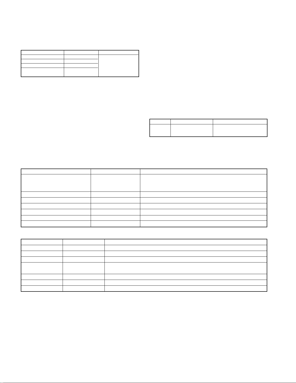
Display
Value Voltage
TOC
recording
power
Actual power output
00H 2.50 mW 6E H 1.354 V
01H 2.60 mW 74 H 1.427 V
02H 2.70 mW 7B H 1.513 V
03H 2.85 mW 83 H 1.612 V
04H 3.00 mW 8A H 1.698 V
05H 3.15 mW 93 H 1.809 V
06H 3.30 mW 93 H 1.809 V
07H 3.45 mW 9C H 1.920 V
08H 3.60 mW A6 H 2.043 V
09H 3.75 mW AE H 2.141 V
0AH 3.95 mW B9 H 2.289 V
0BH 4.15 mW B9 H 2.289 V
0CH 4.35 mW C4 H 2.412 V
0DH 4.55 mW CF H 2.547 V
0EH 4.75 mW DB H 2.695 V
0FH 5.00 mW DB H 2.695 V
• POWER
DISPLAY DESCRIPTION
BLANK DISC Non Recorded disc
CAN'T COPY Inhibit to record by SCMS
CAN'T EDIT Inhibit to edit by MD standard
CAN'T REC Inhibit to record by disc damage(10 or more
defects/recordable cluster is 0)
DISC ERROR**
OR : UTOC read error or FTNO>LTNO
(edit/record) permit ALL ERASE only
DO : Start address TNO>endless TNO
(playback) handle poor TNO as 1SG
(edit/record) permit ALL ERASE only
C0 : Write poor data in UTOC0
C1 : Write poor data in UTOC1
C2 : Write poor data in UTOC2
C4 : Write poor data in UTOC4
(play back) playback even if address
roof(C0)
(edit/record) permit ALL ERASE only
DISC FULL
No recordable area
MECH ERR**
10-13 : head poor down
20-23 : head poor up
no disc No disc in the unit
NO TRACKS Disc recorded title only
NOT AUDIO Disc recorded audio signal.
PLAY ONLY Record to music disc
PROTECTED Record disc inhibited to record
READING In mode of reading TOC or UTOC
SRCH ERR** 30 : Search time over in playback, FF or FB
31 : Search time over in REC-PAUSE
32 : Search time over in record
TEMP OVER High temperature
TITLE FULL Input over letter of title
UNIT ERROR Hardware damage
UTOC W ERR Error of writing to UTOC
WRITING In writing to UTOC
9. MD mechanism error message
8-5 Digital Controlled Stereo Audio Processor :
TDA7309 (X29, IC4)
Port Function List
Port No. Port Name I/O Function
1 RECOUTL O Unused
2 SW OUT O Sub woofer output
3 CSM - Soft mute port
4 SDA I Data input
5 SCL I Clock input
6 DGND - GND
7 GND - GND
8 ADD - GND
9 COUT O Center speaker output
10 RECOUTR O Unused
11 NC I Unused
12 LOUDR - Unused
13 NC I Unused
14 CIN I Center speaker input
15 CREF I Reference voltage
16 VS - Supply voltage
17 SW IN1 I Sub woofer 1 output
18 SW IN2 I Sub woofer 2 output
19 NC - Unused
20 NC - Unused
RD-DV5-S/DV7-L/DV5MD-S
21
Page 22

RD-DV5-S/DV7-L/DV5MD-S
DEFINITION CONTENTS CODE BLOCK TIMING
SERVO
TRAY_LOADING_ERR
Tray Loading Error. 0x4000
DCM_TRAYCTL_T(time out 5secs)
FOCUS_SVERR Focus Servo Error. 0x4100
SPINDLE_SVERR Spindle Servo Error. 0x4101
ADSC, Driver LSI, disc
Motor
DCM_DMON_T(time out 10
secs),Time out of checking
stop,Time out of start to turn.
DSC_DM_ERR
DSC Disc Motor Error.
Abnormal FG-period in
DVD, Abnormal turn of
disc motor,
0x4102
ADSC, Driver LSI, disc
Motor
DCM_DMOF_T(time out 10secs),
DCM_DMMODE_T(time
out100ms) Abnormal turn of
disc motor.,
CDC_CLV_ERR
6626 CLVS Failure.
Abnormal FG-period inCD0x4103
ADSC, Driver LSI, disc
Motor
DCM_DMOF_T(time out 10secs)
Setting abnormal CLV
TRAVERSE_ERR Traverse Motor Error. 0x4104
DCM_INNER_T(time out 5secs)
TRACK_SVERR Tracking Servo Error 0x4105
DCM_TRON_T(time out 1sec)
Command error,Focus jump
Lock NG (ReSartServo) NG of
SEEK_TIMEOUT_ERR Seek Time Out Error 0x4106
Over 200 seek times
DSC_ERROR
ADSC
ERROR
ADSC
ERROR
ADSC
ERROR
ADSC
ERROR
ADSC
ERROR
FEP
ERROR
ADSC Command error
DSC_NOTREADY
DSC Not Ready Error
ADSC ADSC REDY time out
DSC_TIM_ERR DSC TimeOut Error. ADSC
Over of CLV OK Over
of command end
DSC_COM_ERR
ADSC No use
DSC_ATN_ERR DSC Attention Error. ADSC
Error of CD-trick play and CD/DVD
seek. FC jump in DVD-play.
INVALID_MDTYP Out of Media 0x4300 ADSC
No check of media, Error after
servo retry. Abnormal disc.
DONOT_QREAD_ERR
0x4302 ADSC
Read error in Cue or
Rev play of CD
DSC_ESCAPE DSC Command Escape - ADSC
Stop servo operation after setting
the ESC flug in mode register of
ADSC.
FEP_IC_ERR
ADSC ,FEP
jitter and data slice offset
adjustment error
FEP
DEFINITION CONTENTS CODE BLOCK TIMING
ODC(Optical Device Control)
MOD_NOT_CRCOK No CRCOK signal 0x4303 (ADSC,ODC,disc ,pickup) Read address error at lead in or focus jump.
MAS_ECC_ERR Abnormal ODC
ODC
ERROR
ODC No emission OK on disc and host in 5 secs.
LAYER_CMP_ERR Abnormal LAYER in seek mode OUT_PB_AREA_NG OUT of PB AREA DATA_TR_PLAY_NG DATA Track Play SEEK_NG_CHGNV No data caused seek error -
UNCORRECT_ERR
No control data by demodulator
error
-
INVALID_CMD_ERR Out of secter ID 0xD601
Over data from disc(DVD : 0xFFF)(VCD :
00:02:00 less)(CD : 0xFFF)
UNCORRECT_LEADIN
No lead-in data by demodulator
error
0xD602 Time over in lead-in.
UNCORRECT_
KEYDET
No lead-in data by demodulator
error
0xD603
(ADSC,ODC,disc ,pickup)
ODC,disc
ERROR CODE OF CIRCUIT BY SELF CHECK MODE (TEST MODE)
CIRCUIT DESCRIPTION
DSC Error
(status data error)
DSC Communication
Failure.
6626 QCODE do not
Read Error.
Adjustment error on data
slice offset
ADSC, TRAY
Mechanism, Motor LSI
ADSC, pickup &
actuator, Driver LSI
ADSC, Driver LSI, feed
actuator, Driver LSI
actuator, Driver LSI
Motor
ADSC, pickup &
ADSC, pickup &
DCM_FCON_T(time out 5secs),
Lock NG, NG of seek.
22
Page 23

RD-DV5-S/DV7-L/DV5MD-S
DEFINITION CONTENTS CODE BLOCK TIMING
DISC
1. No CD-ROM Volume Descriptor
Set, No Primary Volume Descriptor
2. No Beginning Extended Area
Descriptor
3. No NSR Descriptor of "NSR02"
4. Length error of Main Volume
Descriptor Sequence
5. Directry of length error on
VIDEO_TS/AUDIO_TS after root
DISERR_TT_SRP_NO TT_SRP=0 0x2111 Disc format
ISERR_TT_SRP_OVER Value >TT_SRP 0x2112
DISERR_TT_SRP_MISS
0x2113
DISERR_TT_SRP_
PTT_OVER
Value >TT_SRP.PTT_Ns 0x2114
DISERR_TTU_SRP_NO TTU_SRP=0
0x2120 Disc format
DISERR_TTU_SRP_OVER Value >TTU_SRP 0x2121 Disc code
DISERR_PGCI_SRP_NO
PGCI_SRP=0 0x2131
Disc format
DISERR_PGCI_SRP_OVER Value>PGCI_SRP 0x2132
DISERR_TMAP_
SRP_OVER
Value>TMAP_SRP 0x2141
DISERR_TMAP_SA_NO TMAP_SA=0 0x2142
DISERR_TMAP_EN_NO MAP_EN=0
0x2143
DISERR_PGC_PGMAP_NO
C_POSIT is OK,
No PGMAP in PGC
0x2150
DISERR_PGC_PG_NO
C_POSIT is OK, PG=0 in PGC. 0x2151
DISERR_PGC_PG_OVER Value >PG in PGC 0x2152 Disc code
DISERR_PGC_C_PBIT_NO
C_POSIT is OK,
No C_PBIT in PGC
0x2153
DISERR_PGC_C_NO C_POSITis OK, Cell=0 in PGC 0x2154
DISERR_PGC_CN_NO Cell=0 0x2155
DISERR_PGC_C_OVER Value >Cell in PGC 0x2156 Disc code
DISERR_PGC_BLK_NO Block Cell only 0x2157
DISERR_SEARCH_CN_NO
No Cell# in search.
0x2160
Disc format
Disc code
UDF Bridge NG 0x2100
Disc code
Disc format
Disc format
CIRCUIT DESCRIPTION
DISERR_UDF
SRP is not meet with VTSN or
VTS_TTN
23
Disc format
Page 24

RD-DV5-S/DV7-L/DV5MD-S
No. ITEM INPUT SETTING
OUTPUT SETTING
ALIGNMENT
POINT
ALIGNMENT
FOR
FIG.
1
Y LEVEL
100% COLOR BAR DISC
Connect the oscilloscope to
COMPOSITE(X29, J1) output
with 75-ohms resistor
VR301
Y-signal =
1000mV
30mV
FIG.1
2
CHROM LEVEL
100% COLOR BAR DISC
PAL DISC (PAL MODE)
Connect the oscilloscope to
COMPOSITE output(X29, J1)
with 75- ohms resistor
VR304
Chrom-signal =
286mV
14mV
FIG.2
1000mV
30mV
Y
4.7 s
-2.86
0
714
(100IRE)
[mV]
white
yellow
cyan
green
magenta
red
blue
black
714
641
516
443
324
252
127
54
286mV
120
100
14mV
IRE'
Peak white
Blank
Sync. chip
0
-40
ADJUSTMENT
Fig. 1
24
Fig. 2
Page 25

5
1
31
5
3
3
31
19
1
1919
1
19
E35-2877- 5
5
51
5
15
GND
GND
51
5
115
15
13
1
13
1
12
12
1
12
12
1
15
15
27 1
27
23
23
1
21
121
2
1
2
121 23 1
50 1
50
2
15012
50
21 23 27
27 1
E35-2964- 5 E35-2875- 5
E35-2876- 5
E35-2965- 5
E35-2880- 5
DESTINATION
UNIT No.
2-71
COUNTRY ABB.
COUNTRY
DESTINATION
0-22
UNIT No.
ABB.
M2GENERAL MARKET
2
1
1171
17
15
15 1
13
1
13
E35-2878- 5
E35-3147- 5
15 1
15
COLD
HOT
12
2
15
5
VIOLET
VIOLET
ORANGE
ORANGE
YELLOW
BLUE
BLACK
YELLOW
RED
RED
BLACK
GRAY
BLUE
GRAY
19
9
2
1
WHITE
YELLOW
2
13
113
113
13
E35-2879- 5
: AC220V~ 50Hz
: AC240V~ 50Hz
: AC230V~ 50Hz
(V)
(X)
(T,E)
: AC110-120V/
50/60Hz
(M)
ABB.
DESTINATION
GENERAL MARKET
COUNTRY
UNIT No.
0-21M
AUSTRALIA X2 0-71
U.K. T2
2-72
EUROPE E2
U.K. T
EUROPE E
SHANGHAI V2 2-10
ABB.
ABB.
ABB.
DESTINATION
SHANGHAI
EUROPE
U.K.
AUSTRALIA
GENERAL MARKET
COUNTRY
COUNTRY
GENERAL MARKET
DESTINATION
COUNTRY
DESTINATION
UNIT No.
02-72
32-10
00-22
E2
V2
T2
X2
M2
02-71
00-21
UNIT No.
M
UNIT No.
220-240V~
EUROPE
U.K. T
E
WH2-2
WH3
WH4
WH2-1
CN1 CN5
WH1-2
WH1-1
WH5
CN4
WH1
CN3
CN2 WH2
CN6
CN1CN7CN8
CN9
CN603CN604
CN1
CN9
VIDEO
J1
J2
S-VIDEO
P1
RD-DV5-S (X29-2762-71)
RD-DV7-L (X29-276X-XX)
J3
A1
A2
OPT.
IN
OUT
OPT.
J3
SPEAKER
SATELLITE
Lch
Rch
SUB
J2
J1
CN1
FAN
HEADPHONE
J1
CN12 CN14
CN17
CN18
CN5
CN3 CN4
CN2
CN16
WH1
J4
SUB
WOOFER
L
R
AUX
IN
OUT
AUX
R
L
SPEAKERS
WOOFER
PRE OUT
R
L
OUT
CD-R
CD-R
IN
IN
AUX
RD-DV5MD-S (X29-2760-21)
RD-DV5-S (X07-3402-71)
RD-DV5MD-S (X07-3400-21)
RD-DV7-L (X07-34XX-XX)
(X14-7330-00) (C/3)
(X14- )
(A/3)
(X14- )
(B/3)
(X29-276X-XX)
(X35-2302-72)
MD MECHANISM
(D40-1724- 5)
(W02-2783-05) : M,X,V TYPE
TUNER ASS'Y
5)(D40-1723-
DVD(CD) MECHANISM
(X07- )
(A/3)
(X07-34XX-XX) (B/3)
(X07- ) (C/3)
RD-DV7-L ONLY
RD-DV5MD-S
RD-DV5-S
ONLY
(W02-2762-05) : T,E TYPE
RD-DV5MD-S
ONLY
RD-DV7-L
ONLY
RD-DV5-S
RD-DV5MD-S
ONLY
25
WIRING DIAGRAM
RD-DV5-S/DV7-L/DV5MD-S
Page 26

A BDFHJCEG I
R1515
R1516
C1720
R1403
R1408
R1420
C1405
R1803
R1435
C1263
R1118
R1119
C1115
C1113
C1118
C1117
C1119
R1120
R1113
R1117
C1260
R1634
C1619
R1631
R1207
C1262
R1266
R1201
R1203
C1602
R1601
C1611
R1616
C1603
C1607
C1206
XL1201
R1605
C1633
R1633
C1613
R1618
R1205
R1230
C1230
R1231
R1102
C1124
R1121
R1124
R1125
C1121
C1123
C1122
R1122
R1123
C1261
R1264
R1265
R1262
C1107
R1115
R1116
R1112
R1261
R1110
R1111
C1110
C1116
C1114
C1112
R1114
C1111
R1263
C1125
C1265
C1264
L1101
L1201
L1200
L1202
L1100
R1612
R1614
R1802
C1721
R1705
R1703
C1716
C1616
C1700 C1704
R1704
C1305
R1300
C1300
C1301
R1301
R1701
C1303
R1809
R1806
R1716
Q1501
CN1300
IC1302
IC1300
IC1101
D1300
IC1301
Q1807
Q1631
MD MECHANISM (D40-1724-x5)
C1540
C1802
FL1524
R1532
Q1804
IC1801
CN1501
IC1701
IC1802
IC1402
IC1401
IC1201
IC1202
IC1601
CN1101
CN1401
C1530
R1537
C1536
R1538
R1807
R1804
R1407
C1404
R1414
R1463
R1460
C1403
R1534
R1536
R1304
C1340
C1750
C1708
R1443
R1406
R1417
R1418
R1105
C1211
C1161
R1430
C1205
R1211
C1202
C1207
R1214
R1702
C1407
C1806
R1415
C1538
C1534
C1563
C1304
R1529
R1521
C1523
R1535
R1533
C1524
C1510
C1512
R1517
C1715
C1706
C1703
R1441
C1409
R1209
C1266
C1200
C1100
R1101
R1250
R1210
R1215
R1217
C1209
C1208
R1621
C1655
R1624
R1623
R1622
R1401
R1446
R1518
FL1523
FL1525
FL1520
FL1509
FL1512
FL1507
FL1501
FL1518
R1811
C1801
C1201
R1100
C1302
L1300
C1606
C1610
MD MECHANISM (D40-1724-x5)
PC BOARD (Parts layout) Side-A PC BOARD (Parts layout) Side-B
1
2
3
4
5
6
7
2726
Refer to the schematic diagram for the value of resistors and capacitors.
Page 27

1
R1934
R1931
R1932
R1933
CW1933
CW1931
CW1932
SW1932
SW1930
SW1933
SW1936
S
W
19
3
4
C28
R101
R102
R8
C27
C26
C25
C24
R29
R30
R35
R18
C4
R17
R41
R34
R39
R38
R40
R37
C8
C15
C16
C23
C21
C22
C20
C19
C18
C17
R32
R33
C13
C14
R24
R23
C101
C102
R13
R12
R11
R10
R9
R14
R15
C3
C2
R16
R3
R4
R5
R6
R7
R1
R2
R27
R28
R20
R19
C9
C10
C11
C12
C103
R42
C29
132
33 64
4
6
3
1
4613
EB EB
D4
Q1
Q2
IC1
Q3
Q4
D5
POWER
ORANGE
AUX
SOUND
SET/DEMO
/STOP
MD EJECT
STOP
RED
WHITE
BLUE
WHITE
PHONE JACK
VOL/
MULTI
CON.
ST-BY
REC MODE
MD REC
MENU
/RANDOM
/REPEAT
TIMER
TUNER/BAND
/TUNER/BAND
MD PLAY/PAUSE
YEL
ORANGE
OPEN/CLOSE
CD PLAY/PAUSE
BLK
W33
W7
W29
R25
R26
R21
R22
D3
C7
C5
C1
W6
W30W30
W31W31
W11W11
W15
W19
W18W18
W17W17
W13
W14
W36W36
W35W35
W34
W32
W16
W27
W26
W24W24
W12W12
W25
W22W22
W28W28
W23
W21
W20W20
W10W10
W9
W8
W2
W3
W1
W5
W4
1
5
13
1
3
52
2
1
18
19
54
1
3
3
1
6
4
1
5
1
5
E2
WH2-1
J1
A1
WH1-2
D2
D1
E1
CN1
WH5
WH4
S13
S12S12
S11
S10
S9
S8
S14S14
S15
S16
S5
S2
S3
S4
S6
S7
S1
WH1-1
WH2-2
WH3
X14-733/740 A/3 (J70-1535-02)
X14 C/3
ED1
X14 B/3
2
3
KMOQSLNPRT
PC BOARD (Parts layout) MD MECHANISM PC BOARD (Component side view)
4
5
6
7
Refer to the schematic diagram for the value of resistors and capacitors.
28
Page 28

U VXZABADWYAAAC
C3
C43
C121
L628
L634
L636
L638
L632
L630
L640
L642
L646
L644
C233
R106
L213
L208
C229
C228
L209
C230
R238
L203
C231
R239
R237
C237
R110
R107
R109
R108
L211
C129
C41
C39
R30
R29
C49
C240
C220
R226
L204
R233
R232
C232
R225
L212
CF203
C35
C34
C38
R28
C21
R14
R22
R25
R227
C211
R228
C11
C15
C14
C12
C16
L205
R12
R111
C212
R112
C47
C29
R23
C45
C28
R27
C36
C40
C46
C37
R17
C33
C31
R24
C30
C25
R9
L620
L622
L624
L618
L626
L605
C238
C205
C204
C106
C207
R208
C116
C115
R115
C102
C101
R122
C102
R101
R102
R118
R104
R103
R117
C104
C103
R113
R116
R114
R119
C318
L301
L903
L902
L303
L302
L901
C903
C902
C901
C319
C320
R241
C201
R203
R201
L304
R316
C236
C322
C117
C118
R120
R121
R21
R102
C109
C107
C108
C112
C113
C119
C114
C120
C22
L32
L34
C24
R2
R1
C23
C2
C1
L22
L20
L30
L24
L26
L28
R19
R18
C44
R20
R219
C208
R218
R220
C209
C210
R204
R205
R221
L14
L12
L10
L16
L8
C234
L6
R244
C344
C312
C335
C334
C333
R326
C324
C317
C323
R338
R335
R314
R323
R320
R902
R903
R312
R901
R313
R311
C352
L306
R327
C350
C327
R340
R331
C325
C316
C315
C314
C313
C329
C326
C328
R322
R321
C336
C338
R329
L305
R339
R332
R325
R324
R330
R334
R333
R328
CP302
C339
C337
C340
C332
R341
C342
C341
C343
C308
C307
R207
C309
R310
C311
C310
C215
R223
CP307
C506
C505
R505
R507
C348
C347
C349
C346
C305
C345
R309
C306
C304
C303
R506
R406
R409
C406
C503
R502
C401
C407
R407
C402
C403
R402
R403
C502
C501
R501
R401
R7
C42
R11
C19
C18
C20
C8
C7
R10
R13
R8
C17
R5
R4
R3
R6
C6
C4
C5
CF3
CF1
L3
L1
C214
R245
C239
C409
R503
R504
C504
R224
C235
C404
R404
C410
C411
L401
CP301
CF202
CF201
CF607
CF301
C612
CF601
CF602
CF603
CF604
CF605
CF606
1
24
25
48
1
4
5
8
1
8
5
4
3
1
5
4
1
3
5
4
1
5
EB
E
BEBEBEB
W301
D101
IC218
D3
Q201
D203
D102
D4
IC214
IC603
Q304
IC302
Q302
Q303
Q301
D301
IC206
IC215
R248
R206
W609
C13
CP308
C203
C351
VR303
R124
R123
R337
W302
C26
C408
C110
C111
C227
C601
C609
L617
C602
C331
C603
C606
C301
C302
VR304
L906
L907
L905
L645
L641
L643
L904
L647
L648
R26
R34
R31
R32
R33
R15
R16
L206
L27
L29
L25
L35
L202
L33
L31
L631
L629
L627
L637
L639
L633
L635
L616
L649
L615
L613
L614
L623
L625
L619
L621
R317
R318
R315
R408
L307
R405
R202
R209
R240
R236
R214
R215
R216
R213
R210
R211
R212
R222
R217
C216
C226
C206
C123
C124
C122
C202
C126
C127
C128
C321
C32
C9
C10
C605
L17
C405
L9
L11
L5
L7
L13
C608
L15
C330
C353
L19
L21
CP305
CP306
CP304
CP303
L207
L37
L36
L201
L101
L602
L601
L650
W201
C221
X202
C27
R35
R246
C48
CF4
R247
W610
R229
C604
CP309
Cb
C
METAL
MASK
Cr
Y
L651
1
1
27
25
28
26
50
54
209
1
52
53
104
105
156
157
1
24
25
48
1
8
9
16
1
9
10
2
EB
1
25
26
50
51
75
76
100
50
1
1
36
37
72
73
108
109
144
1
25
26
50
51
75
76
100
C125
1
4
5
8
1
8
5
4
8
5
1
4
1
12
13
24
13
4
2
1
2
(2)
(1)
(20)
34
35
(21)
1
2
29
30
1
5
1
3
4
6
1
3
4
5
EB
IC602
IC202
D202
Q203
Q202
D201
D601
D1
IC101
IC210
IC211
IC301
IC501
IC601
IC207
IC216
IC401
IC1
IC201
VR302
VR301
IC217
X35-230/232 (J70-1521-12)
CN603
CN601
CN602
CN604
CN901
IC213
CN201
CN1
C63
R241
R173
C51
C36
C52
C61
R10
R9
R210
R310
R130
R129
R142
R143
R131
C62
R60
R61
R59
R57
R58
R62
R66
R65
R63
R64
R55
R56
R54
R53
R119
R120
R118
R116
R117
R121
R124
R123
R108
R109
R107
R103
R106
R114
R115
C218
R233
R234
R246
R317
R318
R315
R316
R244
R158
R161
R162
R153
R152
R163
R203
R205
R211
R209
R201
R202
R204
C129
C130
C120
C121C122
C219
C143
C37
C281
C205
C38
C87
C86
C90
C91
C89
C3
C50
C107
C49
C114
C103
C96
C97
C54
C95
C100
C53
C98
C99
R21
R23
R22
R26
R27
R24
R25
R14
R13
R12
R11
R16
R15
R38
R37
R31
R32
R29
R30
R35
R36
R33
R34
C15
C7
C8
C16
C30
C24
C19
C20
C23
R2
R252
C1
C2
R253
R212
R112
C282
C225
L2
L3
L5
C229
C215
C228
C227
R240
R239
R321
R69
R1
C75
C73
R3
C140
C102
C203
R237
W7
C144
R113
R74
R73
R43
R41
C69
R67
R42
C70
C83
R48
C79
R49
R50
C80
C84
R179
C81
R52
C82
R51
C77
R47
R187
R185
R191
C112
R248
C139
R258
R171
R172
C29
R243
C145
W3
W4
R259
C152
C151
C68
C142C141
R255
R256
R302
R303
C146
R301
R181
R182
R183
R184
R186
R188
R190
R304
R192
R167
R166
R176
C119
R218
R250
R247
R249
C64
C283
R157
R156
R308
R251
R322
C113
C285
W12
C210
C207
L4
R242
R224
R223
C211
C214
W11
R70
R72
C56
C4
R71
L1
W5
W6
C108
C105
R220
R219
R221
R222
W8
C66
C35
R68
1
8
5
4
1
8
5
4
EB
EB
EB
EB
EB
EB
EB
EB
EBEB
EB
Q3
Q1
Q4
Q2
D1
D12
IC9
D6
Q13
D14
D3
D7
Q14
Q12
Q11
D2
Q9
Q7
Q8
D19
D17
D16
IC21
D11
R4
R309
C60
C28
C27
C59
C66
C65
R127
R128
R140
R139
R138
R141
R137
R133
R132
R135
R134
R102
R45
R101
R126
C284
R312
R313
R311
R314
R235
R154
R155
R159
R160
R146
R147
R144
R145
R148
R151
R149
R150
R170
R169
R164
R165
R168
C42
C128
C133
C134
C131
C132
C126
C44
C124
C125
C41
C135
C46
C43
C45
R19
R20
R18
R17
R28
R46
R44
C13
C14
C12
C11
C74
R7
R8
R5
R6
W1
W2
R180
R76
C76
R245
R236
R238
R254
C137
R306
R178
R325
R305
R208
C138
R206
R207
R319
R320
C222
R257
C233
R40
R39
R260
R189
R193
R174
R197
R198
R194
R195
R199
W13
R177
R213
R307
R200
R196
R217
R215
R216
W10
R122
C208
R323
R324
R232
C209
C55
C212
L6
R125
R75
W14
W15
X2
C13
P2
C104
C101
C136
C10
C18
C25
C26
C6
C217
C32
C31
C226
C5
C17
C22
C21
C110
10MHz
32.768KHz
4.332MHz
C72
C71
C85
C78
C204
C224
C223
C57
C48
C115
C47
C109
C127
C202
C123
C116
C118
C93
C92
C94
C117
C220
C286
C106
C206
C88
C221
R104
C58
C201
C34
C33
C216
C147
C148
C150
C213
C111
R105
X1
X3
P1
R136
R175
12
1
2
27
26
1
2
21
20
1
2
23
22
1
2
19
18
1
5
B
E
1
2
12
13
1
5
4
2
I
G
O
1
15
1
5
4
2
1
2
14
15
1
10
11
20
12
9
1
1
24
13
12
G
I
O
G
I
O
E
B
E
B
E
B
1
7
8
14
1
8
9
16
1
4
5
8
1
7
8
14
1
7
8
14
1
30
31
50
51 80
81
100
1
24
25
40
41
64
65
80
1
14
15
28
18
9
16
1
4
5
8
1
8
16
9
W9
IC7
IC15
IC1
IC3
D5
D4
D9
D8
IC8
IC6
IC18
IC16
D10
IC5
IC17
IC20
Q10
D15
D13
Q6
D20
D18
Q15
CN5
PROTECTION
IC19
Q5
H-VDD
CD-DATA
CN1
CN9
CN8
IN-SW
NRST
B/Cb
M+9V
NC
KEY1
CN4
GND
HPLch
CN7
IC12
CN3
HPRch
MD+5V
IC13
-30V
WH1
IC14
CN6
ST
PLLCE
IC4
X29-276/283 (J70-1534-11)
IC11
IC10
E3
CN2
C-SW
TEMP-P
A3
J3
J2
J1
A1
A2
OUT
IN
SVIDEO
VIDEO
VIDEO OUT
IN
OUT
OPTICAL
AUX
OUT
IN
IN
CD-R
AUX
PC BOARD(Component side view
)
1
2
3
4
5
6
7
21 22
Refer to the schematic diagram for the value of resistors and capacitors.
Page 29

AE AG AI AK AMAF AH AJ AL AN
C522
C516
TH1
C51
C1
R153
C15
R63
R110
R109
C16
R152
R151
C13
R209
R59
R210
R61
C14
R204
R74
R73
R80
R84
R82
C18
R70
C17
R68
R69
R86
R65
R105
R106
R108
R107
R67
R101
R102
R104
R103
R403
R504
R354
R353
R355
R402
R356
R516
R506
R219
C10
R220
R251
R212
C12
R217
C11
R252
R306
R305
C7
C3
C4
C9
R253
C8
R304
R303
C305
C208
C220
R517
R520
R521
R518
R519
C80
C102
C62
C63
C104
C107
C207
C105
C106
C306
R527
C520
R529
R532
R533
R530
R531
C355
C356
R523
R526
C512
C61
R20
R19
R23
C23
R18
R15
R14
R17
R16
R24
R53
R51
R57
R55
R29
R26
R25
R28
R27
R13
C57
R6
C59
R2
R4
R3
C53
R5
R7
R10
R11
R12
R9
R1
R8
R522
C27
C204
W603
W602
W903
W901
W902
C219
C203
R222
C307
C308
W652
C506
C519
R155
C521
W904
C24
C26
C25
W998
R208
R223
C81
R81
R513
R112
C403
1
5
4
3
C101
C2
R221
1
8
5
4
R213
C60
W601
BE
EB
BE
EB
EB
EB
EB
BE
BEBEBE
BE
EB
B
E
B
E
BE
BE
BE
EB
EB
C601
TH2
R601
Q303
Q15
Q5
Q304
Q16
Q301
Q302
Q17
Q18
Q3
Q307
Q306
Q308
Q1
Q2
D317
D301
D8
D319
D9
D318
D302
D309
D313
D310
D312
D305
D304
D303
D307
D314
D306
D5
D6
D7
IC11
D10
D3
IC4
D323
D320
Q9
Q8
Q7
Q6
Q10
D321
D322
D311
MD5V
DVD5V
DVD3.3V
DVD9V
FL
3.3&5V
S6
S4
S3
S2
SWch+
GND
Rch
GND
Lch
SWch-
CN7
CN6
D103
D102
D101
D105
D104
Q13
Q14
J1
D2
D4
D1
IC2
IC1
D16
D15
D18
D17
D12
D13
D14
D11
D316
D19
D315
L&R&C&SWch
AMP OUT
SPEAKER
POWER SUPPLY
5.1VAVR
PROTECT
J4
-3 0VAVR
(J70-1502-11)
L&Rch
C&SWch
C&SWchMUTE
L&RchMUTE
CN1
CN2
CN5
CN4
CN3
IC3
J2
CN12
CN14
D308
E1
Q11
J3
E2
CN16
CN18
IC15
CN17
2A 125V
+9&+8&-9V
MD5&3.15V
X07 B/3
WH2
AC
SATELLITE
PRE OUT
SUB WOOFER
WOOFER
SUB
SPEAKERS
DVD9VAVR
DVD3.3VAVR
DVD5VAVR
Q311
IC13
IC12
WH1
E3
MD5VAVR
IC14
X07C/3
X07-340/343 A/3
E B C
O G I
O G I
G I O
15
15
2
1
C6
C5
C55
C103
W407
R216
C218
R211
R218
C206
R505
R503
C523
C513
R514
R515
R512
W424
W15
R214
C21
C351
C352
C302
C301
C304
C303
C603
C402
C607
C605
C401
C354
C353
C209
C205
C22
C518
C514
C20
C82
C211
C213
C215
C214
C216
R352
R307
R202
R351
R534
R308
R524
R302
R401
R528
R71
R21
R22
R111
R525
R72
C253
C210
C504
C505
C502
C503
C507
C221
C511
C508
C701
C19
C509
C517
C212
C251
C252
W413
W412
W416
W411
W7
W92
W88
W3
W14
W16
W35
W414
W13
W415
W47
W53
W58
W36
W8
W5
W9
W98
W417
W420
W44
W423
W422
W419
W418
W11
W17
W21
W27
W28
W32
W402
W401
W59
W38
W72
W70
W71
W61
W42
W69
W68
W77
W66
W67
W46
W65
W64
W76
W63
W57
W73
W74
W54
W6
W453
W29
W454
W458
W456
W252
W251
W34
W25
W79
W33
W52
W39
W23
W20
W62
W30
W87
W31
W24
W26
W48
W10
W41
W40
W51
W91
W60
W56
W85
W50
W37
W45
W501
W84
W82
W81
W321
W322
W341
W342
W343
NF
NF
C524
C217
C510
T1
K2
K3
W460
K1
W18
W403
W12
W19
W22
W408
W409
W410
W405
W406
W421
W55
C515
C254
C202
W43
R154
R201
R215
W457
W253
W254
W461
W455
W459
W256
W255
C255
C256
W452
W1
W75
W99
W78
W100
C702
C703
P1
W80
W404
W83
F1
R301
PT
15
1
1
13
12
2
1
2
1
2
1
9
1
13
1
17
O
G
I
1
5
4
2
W4
1
17
B
E
1
9
12
E
B
E
B
1
5
1
2
14
1
2
14
W49
E
1
C
B
O G I
13
W94
W93
I O G
10
C606
C604
C608
W97
W96
W95
O G I
PC BOARD (Component side view)
1
2
3
4
5
6
7
Refer to the schematic diagram for the value of resistors and capacitors.
24
23
Page 30

A BDFHJCEG I
REC HEAD
D1300
CN1101
CN1401
CN1300
RECORDING(DIGITAL)
GND LINE
PLAYBACK(DIGITAL OUTPUT)
RECORDING
PLAYBACK
HEAD
DRIVER
4 BIT
D-RAM
Q1807
EN DEC/ATRAC
EE-PROM
Q1631
CONVERTER
AD/DA
M
M
M
SPN
SLD
LOD
5CH MOTOR DRIVE
AD DATA
DA DATA
ANALOG
OUT(Lch)
DIGITAL
IN
DIGITAL
REC
B LINE
RF SIGNAL
PROCESSOR
EFM OUT
CW1903
CW1931
484746
454443424140393837
36
35
34
33
32
31
30
29
28
27
26
25
131415
16
17
181920
21
22
23
24
1
2
3
4
5
6
7
8
9
10
11
12
1234
1+2
P IN
3+4
PITG
N IN
GND
BIAS
VCC 1
EFMAGC
DCNF
EFMO
2-1
AD AGI
AD AGC
ADIPNF
ADIPO
GND 2
WBO
VCC2
OPICPW
DISC
SGAIN
DTEMP
E OUT
E SW
E IN
F IN
F SW
F OUT
E OUT
B OUT
A OUT
TCGO
TCGI
RF ADD
RF1
RF2
RF3
RF4
REFI
REFO
A OUT
A SW
A IN
B IN
B SW
B OUT
100999897969594939291908988878685848382818079787776
75
74
73
72
71
70
69
68
67
66
65
64
63
62
61
60
59
58
57
56
55
54
53
52
51
2627282930
31
32
333435
3637383940
41
42
434445
4647484950
1
2
3
4
5
6
7
8
9
10
11
12
13
14
15
16
17
18
19
20
21
22
23
24
25
SYRS
SYRDX
SYWRX
SYD7
SYD6
SYD5
SYD4
SYD3
SYD2
SYD1
SYD0
RSTX
D GND
VDD1
DINTX
MCCK
C OUT
SENSE
FOK
SFSY
SBSY
SBO
SBCK
TEMON
TOTMON
FEMON
DA DATA
AD DATA
DFCK
BCLK
LRCK
D GND
VDD3
D OUT
D IN
XO
XI
D GND
VDD1
VPD
VXI
CD BCLK
CD LRCK
CD DATA
D IN2
DI LOCK
TEST1
TEST0
TCRS
X700KO
RAA3
RAA2
RAA1
RAA0
RAA10
VDD2
RAA4
RAA5
RAA6
RAA7
RAA8
RAOEX
D GND
RACASX
RAD2
RAD3
RAA9
RARASX
RAWEX
RAD1
RAD0
TCRS
ACRCER
PLCK
EFMO
EFMMON
A VCC
EFMI
A GND1
AVCC2
VREF
WBI
TCG
A IN
B IN
E IN
F IN
V BAT
VDD1
D GND
TEST2
X176KO
FODRF
FODRR
TRDRF
TRDRR
SLDRF
SLDRR
SPDRF
SPDRR
31
1
2
3
4
5
6
7
8
9
10
11
12
13
14
15
16
17
18
19
20
21
22
23
24
25
26
27
28
29
30
MD D ATA
4M/16M
64M
LDVAR
ADJS
C IN
UN LOCK
BYTE
CN VSS
STID OUT
SEACH OUT
RESET
VSS
MCCK
VCC
DINT
SFSY
ST-ID
SERCH
MDR SW
CDB SEL
D SENSE
P-DOWN
HD ON
EEPRO
HF ON
EEPK
EEPD
1098765432
1
VCC
A3
A2
A1
A0
A9
RAS
WE
I/02
I/01
11
12
131415
1617181920
A4A5A6A7A8OECAS
I/03
I/04
GND
1
2
3
4
5
6
7
8
9
10
11
12
13
14
15
16
17
18
19
20
21
CH3 IN
OUT3
IN3-
VSS 2
VM2
NC
GND
IN3+
VM3-
VMBF
GND
VM4+
VM4-
VM5+
VM5-
OUT5
IN5-
IN5+
IN4+
IN4-
OUT4
42
41
40
39
38
37
36
35
34
33
32
31
30
29
28
27
26
25
24
23
22
REG+
REGR
IN1+
VBS1
VM1
IN1-
OUT1
VM1-
VM1+
GND
VM2+
VM2-
OUT2
GND
IN2-
IN2+
MUTE1
MUTE2
SS.GND
VREF
VRRFO
1
2
3
4
D1
S1
S1
G1
8
7
6
5
D2
S2
S2
G2
1
2
D1
D2
5
4
3
G1
S
G2
543
1
2
1
2
3
4
A0
A1
A2
VSS
8
7
6
5
VCC
WP
SCL
SDA
14
131211
10
9
8
VCC
1
2
3
4
5
6
7
GND
28
27
26
25
24
23
22
21
20
19
18
17
16
15
14
13
12
11
10
9
8
7
6
5
4
3
2
1
SW
+2.8V
B
LVV OUT
APC OUT
LD VCC
D GND
D GND
LD ON
LD VAE
A
COM
RF1
F
E
RF3
RF4
VCC
A GND
MP/R
RF2
APC IN
D GND
LV V IN
F-
T+
F+
T-
9
8
7
6
5
4
3
2
1
MINF
GND
TRY-
TRY+
SP-
SP+
LEAD IN
SLD+
SLD-
2
1
AGC
ADIP AGC
BPF
DIFF
AND
R
SW
BIAS
SW
MODE
32
35
31
34
R1100 27
10K
R1102
3
72
R1101
1
4.7
C1100
28
0.47uH
L1100
39
R1105
1.2K
0.022
C1107
R1110 680K
100K
R112
680K
R1113
R1111
100K
1
C1111
1
C1110
47K
R1116
330K
R1115
47K
R1117
R1118
330K
R1121
100K
R1120
560K
C1124
0.1
19
20
21
18
22
2.2K
R1124
2.2K
R1125
12K
R1123
12K
R1122
1
C1122
0.22
C1121
0.1
C1123
42
92
38
1
C1116
1
C1113
0.033
C1115
5P
C1112
12K
R1114
0.033
C1114
1
C1117
0.47
C1118
220K
R1119
0.47
C1119
68P
C1305
10
R1301
0.022
C1301
150P
C1300
C1302 10
C1303 1
C1340 100P
56K
R1612
33K
R1614
47uH
L1300
150
R1304
6.8
R1300
220P
C1304
R1266 27K
R1261 27K
R1262 27K
R1264 27K
R1263 27K
C1263 220P
C1264 220P
C1265 220P
R1265 27K
68K
R1205
39K
R1207
100K
R1203
56K
R1201
23
25
21
19
0.1
C1211
10
C1201
22P
C1266
C1261
220P
220P
C1262
1
C1200
18
19
22
20
21
1
C1205
R1209
100
R1211
220
72
70
71
73
74
C1206
0.01
1
C1207
R1215
1M
R1217
150 12P
C1209
12P
C1208
XL1201
C0001AW
10K
R1214
R1250
00
32
262729
28
333435
363739
40
42
41
42
29
282726
32
40
393736
353433
41
1
C1202
0.47uH
L1201
0.1
C1260
4.7uH
L1200
4700P
C1611
12K
R1616
4.7
C1610
C1619
330P
0.01
C1613
22K
R1618
R1624
6.8K
C1655
0.01
R1623
22K
R1622
22K
6.8K
R1621
12
14
15
13
10
9
12K
R1605
680P
C1603
19
31
32
34
35
470P
C1602
R1601
12K
21
10K
R1460
10K
R1463
R1418 1K
R1417 1K
R1406
10K
0.1
C1403
R1414
220K
0.01
C1404
R1415
1K
20
21
3
31
2.7K
R1401
3.3K
R1407
12
0.047
C1633
68K
R1633
100K
R1634
+
C1616
100u10
300K
R1631
10K
R1230
1
C1230
10K
R1231
82
83
1
C1607
66
57
58
59
10uH
L1101
1
C1125
98
99
100
96
95
97
92
93
94
80
86
90
89
91
858483
81
827879
28
26
26
25
9
14
15
10
12
13
93
C1700
47u4
0.01
C1706
C1708
0.01
R1703
3.9
330P 330P
C1720
R1704
3.9
+
C1721
R1705
3.9
C1750
0.1
0.1
C1703
47u4
C1704
+
VADCP
VADCN
V IN R
VREFA
V IN L
VDDA2VSSA
1
543
876
MC1
V OUT R
VDDO
V OUT L
VSSO
VREFD
2728242526
MC2
A VSS
A VDD
212223
84
85
81
86
83
23
91
24
2
1
3
4
5
6
7
8
9
10
11
12
14
13
15
16
21
19
18
17
20
22
23
25
26
28
27
T.COIL
F.COIL
I/V
I/V
I/V
I/V
4
5
GND
6
7
8
3
2
1
VCC
4
3
4
3
2
1
5
4
3
7
6
8
9
470
R1932R1931
1K
R1934
180
560
R1933
P0011AW
SW1930
WRITE
PRO
M0007
SW1932
LOAD
SW1933
M0007
REC
M0007
SW1934
PLAY
MO157
SW1936
LRAD IN
CW1932
CW1933
0.47uH
L1202
434446
45
434446
45
+3.2V
+3.2V +3.2V
+3.2V
+3.2V
+3.2V
+3.2V
+3.2V+3.2V
+3.2V
+3.2V
+B
IC1101
1000P
C1161
1
C1563
C1606
10
220
R1210
R1408
3.3K
680P
C1405
0.1
C1407
+3.2V
+B
+B +B
+B
+B
+B
+B
+B
+B
+B
+B
+B
+B
+B
+B
+B
+B
+B
+B
+B
+B
+B
+B
+B
+B
+B
+B
+B
+B
+B
+B
+B
+B
+B
+B
+B
+B
IC1101
IC1201
IC1202
IC1601
IC1301
IC1302
IC1402
IC1300
IC1701
PICKUP
MD MECHANISM (D40-1724-X5)
LOADING PWB
LEAD IN PWB
3.2V
3.2V
1.3V
2.6V
5.0V 5.0V
4.9V
5.0V
1.6V
1.6V
1.6V
2.6V
2.3V
2.4V
2.4V
2.5V
2.5V
2.5V
1.6V
1.6V
1.2V
1.2V
1.6V
1.6V
1.6V
3.2V
1.6V
1.6V
2.6V
2.4V
2.6V
2.3V
1.7V
1.6V
1.6V
1.4V
1.6V
1.6V
1.7V
2.5V
1.5V
1.5V
1.2V
1.3V
1.3V
1.3V
1.3V
1.6V2.6V
3.2V
1.3V
1.6V
1.6V
3.2V
1.5V
1.5V
0V
3.2V
2.5V
3.2V
REC
PLAY : 0V
: 1.6V
5.0V
3.2V
1.6V
1.6V
1.6V
1.6V
3.1V
0.2V
3.2V
3.2V
3.2V
3.2V
3.2V
0V
0V
3.2V
0V
3.2V
3.2V
3.1V
3.2V
3.2V
3.2V
1.6V
1
2
3
4
5
6
7
Page 31

KMOLN
CN1501
SYSTEM u-COM
Q1804
AVR
+2.6V
+3.2V
AVR
CD DATA
ANALOG
REC IN(Rch)
IC1101 : IR3R58M
IC1201 : LR37816A
IC1202 : IX2474AF
IC1300 : 74ACT02T
IC1301 : FTD2005
IC1302 : CPH5608
IC1401 : IX0423AW
IC1402 : 58X2402T or
IC1601 : M56788F
IC1701 : UDA1345TS
IC1801 : XC62EP32
IC1802 : XC62FP26P
Q1501 : UN2214 or
Q1631 : 2SC2712GR or
Q1804 : 2SB1205
Q1807 : U2SD601AR or
D1300 : SBE803
Q1501
3/5
CN1
X29-
CAT24WC02U
DTC114YK or
RNC1407
KRC107S or
2SC3052F or
2SC3875GR or
2SD601AR
2SC3875GR or
2SC3928AR
100999897969594939291908988878685848382
81
80
79
78
77
76
75
74
73
72
71
70
69
68
67
66
65
64
63
62
61
60
59
58
57
56
55
54
53
52
51
32
333435
3637383940
41
42
434445
4647484950
Q/N
AVCC
VREF
GND
TEST-K
TESTK1
MINF
DTEMP
AVCX1
AVCX2
AVCX3
TEST0
TEST1
TEST2
RAST
MUTE
LD-
LD+
ADMUT
XRST
07/120
5/3
DFS1
DFSO
DAP ON
SB8Y
A/B
LDON
LAST
PCNTO
L3 CLK
L3 MODE
L3 DATA
GND
INNER
VCC
CRTRG SW
SLOT5
SLOT4
SLOT3
SLOT2
SLOT1
SYSD0
SYSD1
SYSD2
SYSD3
K DATA
DSCK
DSTB
SBO
SBCK
DISC
R/P
FOK
FLASH L
S GAIN
SYRS
SYRD
SYWR
FRASH H
SYSD7
SYSD6
SYSD5
SYSD4
27
26
25
24
23
22
21
20
19
18
17
16
15
14
13
12
11
10
9
8
7
6
5
4
3
2
1
CD DATA
CD BCK
CD LRCK
MD-ST
SERCH
RESET
R IN
AA.GND
L IN
A VCC
R OUT
C GND
L OUT
M.GND
DIGIN
D.GND
D.GND
PCCONTO
M.GND
MD D ATA
D VDD
D VDD
K DATA
DSCK
H.GND
DSTB
H.VDD
82
79
78
38
94
97
96
95
98
99
100
42
R1430
10K
R1435
10K
34
33
32
90
93
91
92
89
R1443
1K
C1409
1
66
65
67
80
R1446
10K
1K
R1420
92
R1403
270
FL1525
FL1523
FL1524
R1533 1K
R1535 1K
C1524 100P
C1523 100P
R1532 27K
C1540 150P
R1516 220
FL1520
R1515 220
FL1518
R1518 47
C1512 100P
R1517 47
C1510 100P
R1529 220
FL1512
C1530 100P
R1521 1K
FL1509
R1537 1K
FL1507
C1536 47P
R1536 1K
C1534 47P
R1534 1K
C1538 100P
R1538 1K
FL1501
12
21
20
31
32
33
34
66
57
59
58
82
83
39
73
VSSD
DATAO
R1702
33K
R1701
47K
VDDD10MP1
11
9
DATAI
MP5
18
19
20
74
+
C1716
47u4
SYSCLK
14
13
12
67
66
65
MP3
MP2
MP4
BCK
WS
151617
R1716
71
70
72
100K
72
C1801
10
5
2
1
43
33K
R1803
C1802
56K
R1802
10
INOUT
1
C1806
GND
R1811
1
R1809
1
R1806
1
27K
R1807
390
R1804
91
93
R1441
47K
+3.2V
+3.2V
+3.2V
+2.6V
+3.2V+3.2V
+3.2V
+3.2V
0.1
C1715
+3.2V
+B
+B
+B
+B
+B
+B
+B
+B
+B
+B
IC1401
IC1801
IC1802
MD MECHANISM (D40-1724-X5)
RD-DV5/DV7/DV5MD (1/5)
A
2.6V
1.0V
0V
1.6V
1.6V
3.1V
1.6V
3.2V
3.2V
3.2V
3.9V
4.1V
4.7V
5.0V
3.1V
5.0V
5.0V
3.2V
2.8V
1.5V
1.9V
1.8V
3.2V
3.2V
0V
3.2V
3.2V
3.2V
3.2V
3.2V
3.2V
3.2V
3.2V
BE-7
CAUTION: For contin-
ued safety, replace
safety critical components only with manufacturer's recommended parts (refer to parts
list). indicates safety
critical components. For
continued protection
against risk of fire,
replace only with same
type and rating fuse(s).
To reduce the risk of
electric shock, leakagecurrent or resistance
measurements shall be
carried out (exposed
parts are acceptably
insulated from the supply circuit) before the
appliance is returned to
the customer.
The DC voltage is an
actual reading measured with a high
impedance type voltmeter with no signal
input. The measurement value may vary
depending on the measuring instruments used
or on the product.
Y39-3950-21
RD-DV5-S/DV7-L/DV5MD-S
Page 32

1
50
49
48
47
46
45
44
43
42
41
40
39
38
37
36
35
34
33
32
31
30
29
28
27
26
25
24
23
22
21
20
19
18
17
16
15
14
13
12
11
10
9
8
7
6
5
4
3
2
1
DGND
DGND
D+5V
D+5V
M+9V
M+9V
M+9V
MGND
MGND
MGND
MGND
MUTE12
MUTE4
DMV
FOIN
TRIN
SPDIN
TRAYIN
TRAYREF
TRVSIN
MUTE3
TRAY/TRV
IN-SW
LDCUR
VREF2
A+5V
RFENV
TSTSG
NARF
ARF
AGND
A+3.3V
A+3.3V
VHALF
FS
FE
TE
AGND
BDO
OFTR
FEPDATA
FEPCLK
FEPENB
AGND
TBAL
FBAL
AGND
GAINH/L
HFMON
AGND
L35
L34
L33
L32
L31
L30
L29
L28
L27
L26
L25
L24
CF4
L21
L22
L20
L19
CF3
L17
L16
L15
L14
L13
L12
L11
L10
L9
L8
L7
L6
L5
W1
4.7uH
L1
L3 10uH
CF1
220u6.3
+
C48
100
99
98979695949392919089888786
85
2627282930
31
32
333435
3637383940
41
42
43
1
2
3
4
5
6
7
8
9
10
11
12
13
14
15
16
17
18
19
20
21
22
23
24
25
AD3
AD4
AD5
AD6
25VDD
25VSS
PBAL
MONC
MONB
MONA
CPUDTOUT
CPUDTIN
CPUCLK
CPUIRQ
ENC
ENS
VFOSHORT
AVDD
HPFIN
HPFOUT
AVSS
LPFIN
LPFOUT
NC(CMPIN)
TRCRS
VCOF
DBAL0
JLINE
AVDD
LOUT
ROUT
AVSS
GBAL
TBAL
AD2
AD1
AD0
AVDD
DA1
DA0
AVSS
ARF
NARF
IREF1
IREF2
DSLF1
DSLF2
AVDD
VHALF
PLPG
PLFG
VREFH
RVI
AVSS
PLFLT1
PLFLT2
JITOUT
NC(RFDIF)
CSLFLT
R4 15K
C4 1000P
R5 15K
C5 330P
C6 330P
R6 15K
1
R11
10uH
L36
47u6.3
+
C13
1500P
C14
R7 18K
C7 680P
C8
R8 16K
560P
C10 0.1
C9 0.1
C11 6800P
C12 680P
1M
R9
1500P
C15
C16 0.1
C17 0.1
R15
R16 27K
27K
R13 12K
5.6K
R10
R12 15K
C18 47P
C19 0.018
C20 1000P
R17 47K
1500P
C33
0.01
C32
2.2
R14
R31
12K
0.47
C37
C36
1500P
2.2
R28
R27
C34
0.039
C35
8200P
R32 4.7K
R29 22K
C23
0.1
C22 1500P
C1 1000P
R1 15K
C2 1000P
C3 1000P
R2 15K
R3 15K
5
6
7
8
Q
CLR
PR
VCC
4
3
2
1
GND
Q
D
CK
Q
VCC
PR
CLR
8
7
6
5
3
2
1
Q
D
CK
4
GND
1500P
C220
1500P
C221
IC210,211
L204
R226 220
13.5MHz
L205
16.9344MHz
1
2
3
4
5
6
7
8
9
10
11
12
VDD
VSS
MO1
MCK
MLEN
VDDA
VSSA
XTI
XTO
NC
NC
SO1
24
23
22
21
20
19
18
17
16
15
14
13
MO2
FSEL/MDT
SO5
NC
SO2
VDD1
VSS1
NC
SO3
SO4
VDD2
VSS2
2.2
R236
C228
L209
CF201
L208
1500P
1M
R237
27MHz
15P
C231
1000P
C237
390
R239
C230 12P
1M
R238
X202
L211
C229
C233
1500P
1500P
C232
L213
L212
R248
22K
1500P
R225 220
27MHz
55
38
99
5
32
52
33
6
29
28
56
51
97
18
100
8
9
50
1
3
49
SO1
47
SEN
SCLK1
2.2
59
97
99
100
1
3
5
6
8
9
54
44
43
43
HFMON
W609
CPSEN
ADSCEN
SCLK1
ADSCINT
SO1
SI1
18
CLKSEL
99
+9V
+9V
+3.3V
+3.3V
+2.5V
+3.3V
+3.3V
+3.3V
+B
+B
+B
+B
+B
+B
+B
+5V
+B
+B
+B
+B
+5V
+5V +5V
+5V
1
R20
CN1
DIGITAL
CONTROLLER
SERVO
D-EF
CLOCK
GENERATOR
IC1 : MN67706EC
IC101 : MN103S13BGA
IC201 : MN120L62GGB
IC202 : PST596JNR
IC206 : X25057M-2.7
IC207 : 49LV8192A90T
IC210,211 : TC7WH74FU
IC213 : SM8703AV
IC217 : TC7WH157FU
IC218,302 : TC7SHU04FU
IC301 : MN677533MP
IC401 : K4S641632ET75 or
IS42S16400-7T or
57V641620HGTH
IC601 : PQ025EZ01ZP
IC602 : PQ1R33
IC603 : PQ018EZ01ZP
Q201 : 2SC4081(R,S)
Q202,301,304
: 2SA1576A(R,S)
Q203 : DTC124EUA
D1,201,601 : MA111
D3,4,101,102,202,
203,301 : DA204U
D1
MAIN
SIGNAL
IC1
IC210
IC211
IC213
(X35-230X-XX)
TRAVERSE
5.0V
9.0V
5.0V
3.3V
2.5V
3.3V
3.3V
3.3V
3.3V
3.3V 3.2V
3.2V
2
3
4
5
6
7
P QSRT
Page 33

UWYAAACVXZABAD
84
83828180797877
76
75
74
73
72
71
70
69
68
67
66
65
64
63
62
61
60
59
58
57
56
55
54
53
52
51
44
45
464748
49
50
XRESET
TX
33VDD
33VSS
DAT0
DAT1
DAT2
DAT3
CHCK40
33VDD
33VSS
TEST
MINTEST
NCLDCK/JUMP
SUBC
IPFLG
DACCLK
NTRON
DACDATA/LG
DACLRCK/JMPINH
NC(IDHLD)
SBCK/PLLOK
BLKCK/CPDET1
LRCK/CPDET2
IDGT/TEMUTE
DTRD
25VDD
25VSS
TILTN
TILT
TILTP
FG
SPDRV
TRSDRV
FBAL
33VSS
33VDD
OFTR
SYSCLK
BD0
TSTSG
R33 4.7K
R30 56K
C38
1500P
4.7K
R34
0.1
C39
R25
C30 0.047
R24
C31
1500P
C28
R26
1500P
C29
12K
12K
0.1
47K
1
47u6.3
+
C27
R22 1
R21 1
10u16
C26
+
R19 1
C25
1500P
R18 1K
C24
0.01
108
107
106
105
104
103
102
101
1009998979695949392919089888786
85848382818079787776757473
72
71
70
69
68
67
66
65
64
63
62
61
60
59
58
57
56
55
54
53
52
51
50
49
48
47
46
45
44
43
42
41
40
39
38
37
1
2
345
678
9
10
11
12
131415
1617181920
21
22
232425
2627282930
31
32
333435
36
109
110
111
112
113
114
115
116
117
118
119
120
121
122
123
124
125
126
127
128
129
130
131
132
133
134
135
136
137
138
139
140
141
142
143
144
SBCK
VSS
P0
P1
PVDD
PVSS
VDD3
OSCO1
OSCI1
VSS
LRCK
BLKCK
IPFLG
DACCLK
DACLRCK
DACDATA
NTRON
LG
JMPINH
IDHOLD
PLLOK
CLKOUT2
VDD
NRST
MMOD
VSS
CPDET1
CPDET2
BD0
IDGT
DTRD
TEHLD
VDD3
CLKOUT1
CPUDT0
CPUDT1
CPUDT2
VSS
CPUDT3
CPUDT4
CPUDT5
VSS
VDD
PTESTDRAM1
PTESTDRAM0
CPUDT6
CPUDT7
VDD3
NRD
NWR
NCS
CPUADR0
VSS
CPUADR1
CPUADR2
CPUADR3
CPUADR4
CPUADR5
CPUADR6
CPUADR7
CPUADR8
CPUADR9
CPUADR10
CPUADR11
PVDDDRAM
CPUADR12
CPUADR13
CPUADR14
CPUADR15
PVSSDRAM
CPUADR16
CPUADR17
HDD15
HDD0
HDD14
VDD3
HDD1
HDD13
HDD2
VSS
HDD12
VDD
HDD3
HDD11
HDD4
HDD10
VDD3
HDD5
HDD9
VSS
HDD6
HDD8
HDD7
VDD3
NRESET
MASTER
NINT0
NINT1
WAITODC
NMRST
DASPST
VDD3NCP2
UATASEL
VSS
PVSSDRAM
PVDDDRAM
SUBC
XCLDCK
CHCK4
DAT3
DAT2
DAT1
DAT0
VDD3
SCLOCK
SDATA
MONI3
MONI2
MONI1
MONI0
VSS
NEJECT
VDD
NTRYCL
NDASP
NCS3FX
NCS1FX
VDD3
DA2
DA0
NPDIAG
VSS
DA1
NIOCS16
INTRQ
VDD3
NDMACK
IORDY
NIORD
VSS
NIOWR
DMARQ
R113 47K
R114 47K
75
76
77
78
80
81
82
83
R115 47K
R116 47K
R117 47K
R118 47K
R119 47K
R120 47K
1500P
C115
C116
1500P
C117
1500P
C118
1500P
R121 1K
C119
1500P
1500P
C120
ADR17
ADR16
ADR14
ADR15
ADR12
ADR13
ADR11
ADR10
ADR9
ADR8
ADR7
ADR6
ADR5
ADR2
ADR4
ADR3
ADR1
ADR0
ODCCS
NRD
NWR
DT14
DT15
DT12
DT13
DT11
DT10
1500P
C114
1500P
C113
1500P
C112
1
R112
R109 1
R111 1
R110 1
10uH
L37
72
WAITODC
ODCINT
10u16
+
C111
R108 1
DT9
DT8
1500P
C109
L101
80
81
82
C108
0.01
1
R106
C107
1500P
R105
1K
88
90
91
92
95
96
97
R107
1
1500P
C106
C105
1500P
109
110
111
112
113
115
114
R123 47K
R124 47K
1500P
C101
C102 1500P
47K
C103
1500P
R122
R101
47K
47K
R102
R103
47K
R104
47K
C104
1500P
71
70
73
81
82
90
88
92
91
95
109
96
110
111
112
113
115
114
97
80
16
27
R207
OSCO
CPUADR4
10K
ADR4
MODE
25
26
+3.3V
L202
C205
1500P
SYSCLK
+3.3V
ADR3
XI
OSCI(CLK135)
24
23
VDD
XO
22
21
SYSCLK(AVDEC)
18
VSS
20
19
VDD
CPUADR3
17
CPUADR14
CPUADR13
CPUADR12
AVDD
CPUADR11
CPUADR10
CPUADR9
CPUADR8
CPUADR7
CPUADR6
CPUADR5
ADR8
ADR7
ADR6
ADR5
ADR11
ADR10
ADR9
+3.3V
30
29
28
34
33
32
31
ADR14
ADR13
ADR12
37
36
35
+
C203
47u6.3
NWEH(ODC/AVDEC/SRAM/ROM)
97
10
ADR0
1500P
C204
ADR2
ADR1
FRD
+3.3V
SDATA
CPUADR0
CPUADR2
15
CPUADR1
14
SDATA(VDAC)
FRD(ROM)
WORD
13
12
11
ODCCS
SCL
AVCS
R205 10K
NWR
ODCCS(ODC)
SCLOCK(VDAC)
ROMCS(ROM)
AVCS(AVDEC)
9
8
7
CLKSEL2(RAMCS(SRAM))
5
6
4
98
99
100
100
R204 10K
NRD
WAITODC
NRD(ODC/AVDEC/SRAM)
NWEI.
3
2
WAIT
1
CPUDT13
CPUDT14
CPUDT15 DT15
DT14
DT13
89
90
91
92
93
94
95
96
CPUDT9
CPUDT10
CPUDT11
CPUDT12
CPUDT6
CPUDT7
CPUDT8
VSS
CPUDT5
DT12
DT11
DT9
DT8
DT10
DT7
DT6
DT5
+3.3V
R247
C210
1500P
3217
ADR5
24
ADR2
ADR4
ADR3
23
22
ADR6
ADR7
21
20
ADR8
ADR18
19
18
FRDXCEA4
25
A1 A0
A2A3XCE
VSS
26
27
ADR1
A5A6DQ0
DQ8
28
29
A7
A17
DQ1
DQ9
30
31
DT8
DT0
DT1
DT9
DT6ADR10 DQ6A9
12
ADR19
16
15
14
13
10
NWR
11
ADR9
9
8
37
DQ3NC
A18
XBSY
DQ2
DQ10
33
34
NC
RST
DQ11
VDD
35
36
DT3
DT10
DT2
DT11
+B
39
XWENCDQ4
DQ12
38
NCA8DQ5
DQ13
40
41
DT4
DT12
DT5
DT13
3
5
ADR12
ADR11
7
6
ADR14
ADR13
4
ADR15
ADR16
2
1
46
44
A10
A11
DQ14
DQ7
42
43
A12
A13
DQ15
VSS
45
DT7
DT14
DT15
XBYTEA14
A15 A16
47
48
ADR17
+B
0.1
C216
R223
1K
0.01
C215
W201
L206
10uH
L207
1500P
C226
10u16
+
C227
10u16
C110
+
220
R228
220
R227
1
2
3
4
A
B
Y
GND
8
7
6
5
VCC
ST
SEL
Y
1
3
2
5
4
C240
1500P
CF203
CF202
100
R233
R232 1
IC217
1
2
3
4
5
VIN
ON/OFF
VOUT
NC
GND
VOUT
NC
GND
4
5
1
VIN
ON/OFF
2
3
C605
1500P
C612
1500P
220u4
+
C603
123 4 5 6 7 8 910
D+3.3V
RESERV
KMODE
SCSIEN
25BSY
196BSY
SBI
SBO
SBT
GND
SCLK1
SO1
SI1
BSY196
BSY25
KMODE
SCSIEN
44
47
49
50
59
56
55
54
52
51
10uH
22
10uH
L201
110
+B
+9V+9V
+3.3V
+3.3V
+3.3V+3.3V
+3.3V
+3.3V
+3.3V
+3.3V
+3.3V+3.3V
+3.3V
+3.3V
+3.3V
+3.3V
+3.3V
+3.3V
+3.3V
+3.3V
+3.3V
+3.3V
+3.3V
+3.3V+3.3V
+3.3V
+3.3V
+3.3V
+3.3V
+2.5V
+2.5V
+2.5V
+2.5V
+2.5V
+2.5V
+2.5V
+3.3V
+3.3V
+2.5V
+2.5V +2.5V
+2.5V
+2.5V
+1.8V +1.8V
+1.8V
+1.8V
+B
+B
+B
+B
+B
+B
+B
+B
+B
+B
+B
+B
+B
+B
+B
+B
+B
+B
+B
+B
+B
+5V
+5V
+B
+5V
+5V
1
C49
C40
10P
C212 47P
C211
47P
10P
C121
C129
1
220
R229
10P
C206
10P
C121
R23
+B
D3
D4
OPTICAL
CONTROLLER
DISC
D102
D101
u-COM
DVD SYSTEM
D202
8M FLASH ROM
DAC CLOCK
SELECTOR
INVERTER
(BOTTOM VIEW)
(BOTTOM VIEW)
+2.5V REG.
+1.8V REG.
CN201
B LINE
GND LINE
SIGNAL LINE
ROM
IC101
IC201
IC207
IC217
IC218
IC601
IC603
(X35-230X-XX)
3.3V
3.3V
3.3V
2.5V
3.3V
2.5V
1.8V
2.5V
3.3V
2.5V
9.0V
3.3V
2.5V
3.3V
5.0V
3.4V
2.5V
3.3V
3.3V
2.5V
3.3V
2.5V
3.3V
3.3V
3.3V
3.3V
2.5V
3.3V
2.5V
2.5V
Page 34

AE AF AH AJ AL ANAG AI AK AM
208
207
206
205
204
203
202
201
200
199
198
197
196
195
194
193
192
191
190
189
188
187
186
185
184
183
182
181
180
179
178
177
176
175
174
173
172
171
170
169
168
167
166
165
164
163
162
161
160
159
158
157
156
155
154
153
152
151
150
149
148
147
146
145
144
143
142
141
140
139
138
137
136
135
134
133
132
131
130
129
128
127
126
125
124
123
122
121
120
119
118
117
116
115
114
113
112
111
110
109
108
107
106
105
535455
5657585960
61
62
636465
6667686970
71
72
737475
7677787980
81
82
838485
868788
89
90
91
92
939495
969798
99
100
101
102
103
104
1
2
3
4
5
6
7
8
9
10
11
12
13
14
15
16
17
18
19
20
21
22
23
24
25
26
27
28
29
30
31
32
33
34
35
36
37
38
39
40
41
42
43
44
45
46
47
48
49
50
51
52
VSS
MA7
MA10
VDD
MA8
MA11
LVDD
MA9
VSS
XCSM
XCSE
VDD
XRAS
XCAS
VSS
XWE
DQMUM
VDD
DQMUE
DQMLM
LVDD
DQMLE
VSS
MCK
VDD
MCKI
VSS
MDQ7
MDQ8
VDD
MDQ6
MDQ9
VSS
MDQ5
LVDD
MDQ10
VDD
MDQ4
MDQ11
VSS
MDQ3
MDQ12
VDD
MDQ2
MDQ13
VSS
MDQ1
MDQ14
VDD
MDQ0
MDQ15
VSS
VDD
VD7
VD6
VD5
VD4
VSS
VD3
VD2
VD1
VD0
LVDD
VCLK
XHSYNCO
XVSYNCO
DCTEST
TESTSEL1
TESTSEL0
PLLTEST
MODE121
ACKIO
NC
AVSS0
VYOUT
COMPY
IREFY
VREFY
AVDD0
VCOUT
COMPC
IREFC
VREFC
AVSS1
VGOUT
COMPG
IREFG
VREFG
AVDD1
VBOUT
COMPB
IREFB
VREFB
APLLAVSS
AVCOIN
ATVROUT
APLLAVDD
VDD
EXTCK
ATCPOUT
APLLVDD
VSS
CLK81
LVDD
VDD
HD3
HD4
HD5
HD6
VSS
HD7
HD8
HD9
HD10
LVDD
HD11
HD12
HD13
HD14
VSS
HD15
AUDSTR
VSTR
VRQ
AVRT M
VDD
STD7
STD6
STD5
STD4
LVDD
STD3
STD2
STD1
STD0
VSS
IECOUT
ADOUT3
LVDD
DACCK
LRCK
SRCK
VDD
ADOUT0
ADOUT1
ADOUT2
VSS
CLKMON
CLK121
VDD
CLK27
PLLAVDD
TCPOUT
PLLAVSS
CKIO
PLLVDD
VDD
MA0
MA6
MA1
VSS
MA5
MA2
MA4
VDD
MA3
TEST9
XRST
TEST8
LVDD
TEST7
TEST6
TEST5
TEST4
VSS
TEST3
TEST2
TEST1
TEST0
VSS
HMD1
HMD0
XHINT
XDK
VSS
XWR
XRD
XCS
HCLK
VDD
HA1
HA2
HA3
HA4
LVDD
HA5
HA6
HA7
HA8
VSS
HA9
HA10
HA11
VDD
HD0
HD1
HD2
VSS
A1
A6
A0
A4
A5
A2
A3
1500P
C303
C304
1500P
C305
1500P100
R309
1500P
C306
100K
CP301
CP307
100K
AVINT
NWR
NRD
AVCS
SYSCLK
ADR1
ADR2
ADR4
ADR3
1500P
C307
C308
1500P
ADR7
ADR8
ADR6
ADR5
ADR11
ADR9
ADR10
DT0
DT1
DT2
C309
1500P
DT3
DT4
DT5
DT6
DT7
DT9
DT8
DT10
DT11
DT12
DT14
DT13
DT15
1500P
C310
1500P
C311
70
71
72
73
757776
78
80
83
81
82
R310
4.7K
C312
1500P
C313
1500P
1500P
C314
22P
L302
220
R312
89
90
22P
L303
220
R313
99
C315 10P
R314 47K
1500P
C316
C317
1
1500P
C324
C323
1500P
110
1500P
C326
1500P
C327
10K
VR304
7.5K
R323
C335 1
1
C334
C333 1
1500P
C328
C329
1500P
R320
3.9K
VR301
6.8K
C332 1
C330
0.1
R318
7.5K
11K
R317
220u4
+
C331
VR304
VR301
R341 10K
100K
CP302
1
C337
C338
1500P
47
CP303
DQ15
DQ0
DQ14
DQ1
47
DQ3
CP304
DQ2
DQ13
DQ12
1500P
C339
1500P
C340
CP305
47
DQ11
DQ10
DQ4
DQ5
CP306
47
DQ7
DQ6
DQ8
DQ9
R337
CLK
DQMUM
DQMLM
XWE
C341
1500P
C342
1500P
C343
1500P
1500P
C344
1500P
C345
1500P
C346
XCAS
XRAS
XCSM
XCSE
A9
A11
A8
A10
A7
1500P
C347
C348
1500P
10uH
C349
1500P
47u6.3
C351
+
R202
R201
4.7K
C201
100P
4.7K
R203 10K
SUB
GND
3
M/A
2
1
OUT
4
VCC
5
+3.3V
C202
0.1
R241
10K
1500P
C209
VSS
CPUADR19
CPUADR18
CPUADR17
CPUADR16
CPUADR15ADR15
ADR16
ADR17
ADR19
ADR18
39
38
43
42
41
40
CIRCEN(ENC)
AMUTE
KMODE
HFMON
STBPSL
25BSY
CPUADR20
PROGSW
HFMON
BSY25
48
47
46
45
44
50
49
ADSCEN
51
STBTI
FRSW
VDD
FEPEN
CLKSEL
STBDAC2
STBSP1
55
SEN
R244 10K
53
52
54
+3.3V
56
57
58
R219 10K
C208
1500P
R208 47K
1500P
C207
BSY196196BSY
STBDAC1
ADSCEN(ENS)
VSS
WMINT
E2CN
SCSIEN
CPSEN
STBDAC1
59
60
61
SCSIEN
62
63
64
47K
R218
VDD
SCLK0
SI0
SO0
SCLK1
68
SI0
SCLK0
65
66
+3.3V
67
R217 47K
SCLK1
SO0
69
70
R216 47K
R215 47K
R214 47K
81
82
83
84
85
86
87
88
CPUDT2
CPUDT3
CPUDT4
CPUDT0
CPUDT1
RST
VDD
DT4
DT2
DT3
DT1
DT0
+3.3V
76
77
78
79
80
SI1
SO1
PULLUP0
PULLUP1
NMI
AVINT
ICRST
MP3INT
ADSEP
ADSCINT
ODCINT
SO1
SI1
71
72
R213 47K
R212 47K
73
74
75
R211 47K
R210 47K
R209 47K
AVINT
ODCINT
ADSCINT
STBPROG
KMODE
AMUTE
R221 47K
R220 47K
R246
SCLK1
SO1
R206 47K
1
2
3
4
SO
CS
VSS
WP
8
7
6
5
VCC
NC
SI
SCK
R240
1
R222
R245 10K
2.2K
POWER
C214 1500P
R333 75
R334 75
100
CLKSEL
L306
C409 1
220u4
+
C408
+9V+9V
+3.3V
+3.3V
+3.3V
+3.3V
+3.3V
+3.3V
+3.3V
+3.3V
+3.3V
+3.3V
+3.3V
+3.3V
+3.3V
+3.3V
+3.3V
+3.3V
+3.3V
+3.3V
+3.3V
+3.3V
+3.3V
+3.3V
+3.3V
+3.3V
+3.3V
+3.3V
+3.3V
+3.3V
+3.3V
+3.3V
+3.3V
+3.3V
+3.3V
+3.3V
+3.3V
+3.3V
+3.3V
+1.8V
+1.8V
+1.8V
+1.8V
+1.8V
+1.8V
+1.8V
+1.8V
+1.8V
+1.8V
+1.8V
+1.8V
+1.8V
+1.8V
+1.8V
+1.8V
+1.8V
+1.8V
+1.8V
+1.8V
+3.3V
+3.3V
+3.3V
+5V
+5V
+5V
+5V
to ODC/WM
+3.3V
C
Cb/COMP
Cr/C
Y
C301
220u4
+
100
L307
220u4
+
C302
220
R311
92
L301
22P
C318
C320
C319
5.1K
R340
12K
R322
12K
R321
5.1K
R339
1
C411
L401
+3.3V
AV DECODER
D301
C
LEVEL
Y
LEVEL
RESET
Q201
D201
RESET
INVERTER
SIGNAL
D203
EEPROM
Q203
Q202
CONT. FOR
Q202
POWER
SWITCH
IC301
IC202
IC206
(X35-230X-XX)
2.6V
0V
4.6V
3.3V
3.3V
3.3V
3.3V
3.3V
3.3V
3.3V
3.3V
3.3V
9.0V
3.3V
3.3V
3.4V
3.3V
3.3V
Page 35

28
29
30
31
32
33
34
35
36
37
38
39
40
41
42
43
44
45
46
47
48
49
50
51
52
53
54
VSS
A4
A5
A6
A7
A8
A9
A11
NC
CKE
CLK
UDQM
NC
VSS
DQ8
VDDQ
DQ9
DQ10
VSSQ
DQ11
DQ12
VDDQ
DQ13
DQ14
VSSQ
DQ15
VSS
27
26
25
24
23
22
21
20
19
18
17
16
15
14
13
12
11
10
9
8
7
6
5
4
3
2
1
VDD
A3
A2
A1
A0
A10
BA1
BA0
XCS
XRAS
XCAS
ZWE
LDQM
VDD
DQ7
VSSQ
DQ6
DQ5
VDDQ
DQ4
DQ3
VSSQ
DQ2
DQ1
VDDQ
DQ0
VDD
R324 330
R328 100
R332 75
R335 75
R327 1K
R331 100
4
5
6
VOUT
GND
VIN
3
2
1
NA
GND
CNTRL
0.1
C608
C609
220u4
+
C606
1
2
3
4
5
6
7
8
9
10
11
12
13
14
15
16
17
18
19
20
21
22
23
M+9V
M+9V
M+9V
MGND
MGND
MGND
+5V
+5V
+3.3V
+3.3V
+3.3V
SEN+3.3V
DGND
DGND
DGND
DGND
SENGND
V+5V
Y
VGND
C
VGND
CB/COMP
1uH
L605
CF601
CF602
CF603
L613
L614
1
2
3
4
5
6
7
8
9
10
11
12
13
14
15
16
17
18
19
20
21
STBPROG/NRST
SO1
SCLK1
STBDAC1
SRCK
LRCK
DMIX
768FS
DGND(DAC)
D+5V(DAC)
AMUTE
IEC958
POWER
SO0
SI0
SCLK0
MUTE4
TRAYIN
TRAYREF
TRAY/TRV
IN-SW
L648
L630
L631
L632
L633
L634
L635
L636
CF607
L637
L638
L639
L640
L641
L642
L643
L644
L645
L646
L647
R401 1
C401 1500P
DQ0
R402 1
C402 1500P
DQ1
DQ2
DQ4
DQ3
DQ6
DQ5
C403 1500P
R403 1
DQ7
C404 1500P
R404 1
DQMLM
XWE
XCAS
XRAS
XCSM
A11
R408 47K
A10
A0
A1
A2
A3
R405 1
C405 1500P
DQ15
DQ14
DQ13
R407 1
C407 1500P
DQ12
DQ11
DQ10
DQ9
DQ8
C406 1500P
R406 1
DQMUM
CLK
R409 47K
XCSE
A9
A8
A7
A6
A5
A4
C352 0.1
NC VCC
GND
4
5
213
R316
100
L304
R315 1
22P
C322
C321
0.1
220u4
+
C602
220u6.3
+
C601
L601
10uH
21
19
19
21
SO1
SCLK1
STBDAC1
90
89
92
22
AMUTE
POWER
SO0
SCLK0
SI0
38
33
29
32
28
+9V
+3.3V
+3.3V
+3.3V
+3.3V
+3.3V
+3.3V
+3.3V
+5V
+B
+5V
+5V
+5V
+5V
+5V
+5V
+5V
+5V
+5V
+5V
+5V
+5V
+5V
Q301,304
1
100u16
C604
+
L602
10uH
Q301
Q304
+3.3V
REGULATOR
D601
CN603
CN604
64M SDRAM
IEC954
BUFF.
OUTPUT
VIDEO
BUFF.
SIGNAL
SIGNAL
MECHA SW
MAIN CPU
SIGNAL
AUDIO DAC
SIGNAL
VIDEO
ANALOG
POWER
SUPPLY
SIGNAL
POWER
SUPPLY
FRONT-END
MECHA
SUPPLY
POWER
3/5
CN8
X29-
CN7
3/5
X29-
IC401
IC602
IC302
RD-DV5/DV7/DV5MD (2/5)
(X35-230X-XX)
C
B
3.3V
3.3V
3.4V
3.3V
3.3V
3.3V
3.3V
3.3V
3.3V
5.0V
5.0V
5.0V
5.0V
9.0V
5.0V
5.1V
3.4V
3.4V
BR-1
BC-3
AO AQ ASAP AR
CAUTION: For continued safety, replace safety critical components only with manufacturer's recommended parts (refer to parts list). indicates safety critical
components. For continued protection against risk of
fire, replace only with same type and rating fuse(s). To
reduce the risk of electric shock, leakage-current or
resistance measurements shall be carried out
(exposed parts are acceptably insulated from the supply circuit) before the appliance is returned to the customer.
The DC voltage is an actual reading measured with a
high impedance type voltmeter with no signal input.
The measurement value may vary depending on the
measuring instruments used or on the product.
Y39-3950-21
RD-DV5-S/DV7-L/DV5MD-S
Page 36

30
OSC OUT
1
IF IN FM SD AD
F2
10K
VR1
1u50
C65
+
100
R45
4.7uH
L10
T1
1P
C57
0.01
C58
10K 1/4W
R43
11P
C60
47K
R44
T3
R32
680 1/4W
33P
C3
33P
C1
47P
C2
L2
0.022
C20
100K
R2
100K
R1
4P
C8
100K
R3
22P
C7
L6
75
R4
100P
C14
2.2uH
L12
C15 3P
L5
C93 8P
4P
C12
C16 8P 1M
R63
R5 10K
1500P
C10
L4
C9 9P
T4
0.022
C19
220
F1
680
R8
100
R9
750
R18
390
R21
0.022
C37
1.5K
R20
R19 750
200
R23
0.47
C36
20
19
18
17
161514
13
12
11
X OUT
GND
A OUT
A IN
PD
VDD
FM IN
AM IN
IO2
IF IN
1
2
3
4
5
678
9
10
XIN
CE
DI
CL
DO
BO1
BO2
BO3
BO4
IO1
7.2MHz
X1
27P
C47
27P
C48
C53 100P
1K
R28
4.7u35
C44
+
0.022
C45
1K
R30
100P
C42
100
R27
5.6K
R29
3.3K
3.3K
3.3K
1K
10K
L8
C24 12P
C22 3300P
R7 4.7K
10P
22P
C26
33P
C25
680
R12
100
R11
150K
R10
10P
C32
R81
C23
220
R17
R33
R37
R36
R35
R34
1
C34
12P
C27
R79
200
2
354
10 1/4W
R56
1/4W
330
47u16
+
C82
R55
2.2K
R38
C54
100P
R41
3.9K
R42 12K
3.9K
R25
47u16
C52
+
C50 47P
47u16
C46
+
0.022
C29
0.47
C17
+9V
+9V
10K 1/4W
C53 100P
2
GND
7.2MHz
X OUTXIN
C48
27P
1
X1
27P
19
20
C47
CE
100K
1
C34
0.022
R3
100K
R1
C20
10P
220
R17
1.5P
75
R4
R5 10K
C7
C9 3P
C10
680P
C15 5P
2.2uH
C92
100P
L12
L6
L4
C12
C19
0.022 0.01
C58
R43
R81
220
L10
1uH
100
R32
C57
1P
680 1/4W
T1
R80
680P
C6
C8 2.5P
L2
L1
COUNTRY
DESTINATION
YES0-21
UNIT No.
ABB.
C
9P
CN2
YES
C145NOED
YES
IC20
YES 100
R3,4
GENERAL MARKET
M
DESTINATION
COUNTRY
W9
NO
UNIT No.
ABB.
2-71
ABC
NO YES
CN2
9PDEYES
C145
NO NO
IC20
NO NO
R3,4
YES8.2K
W1,2
YES
T
EEUROPE
U.K.
EUROPE NO
U.K.
E2
T2
YES2-72
YES 12PNO
YES
NONO NO YES8.2K
YES
YESNO
NO
NO
COUNTRY
DESTINATION
UNIT No.
ABB.
CBA CN2C145ED IC20
243,318,320,325
R132,135,139,141,200,
319
R311,
R3,4
R312 R316R313
W1,2,9
R317
GENERAL MARKET
M2
0-22 NO NO YES NO YES
0-71
NO
YES
AUSTRALIA
X2
AB
NO
R301,311,
312,316,319
NO
R132,135,139,141,200,243,
313,317,318,320,325
YES YES
316,318,319
R301,312,
311,313,317,320,325
R132,135,139,141,200,243,
W1,2,9
B
+B
C285
15
Q6,
R124
47K
C285
15
Q6,
47K
R124
SHANGHAI V2 2-10
C285
15
Q6,
NO YES
YES
NO
NO
NO NO
10K
R124 R301
NO
NO
YES
+B
+B
GND
AM ANT
CN2
D1
D2
D4
TR2
TR1
TR5
TR14
D5
TR4
TR7
D6
FM 75
D4
TR1
AM ANT
GND
CN2
D1
D9
D2
FM 75
D9
RD-DV5MD-S (X29-2760-21)
RD-DV5-S (X29-2762-71)
RD-DV7-L (X29-276X-XX)
: ADJUSTING PARTS
: ADJUSTING PARTS
1/5
MD
MECHA.
CN604
2/5
X35-
2/5
X35CN603
B LINE
B LINE
GND LINE
SIGNAL LINE
DIGITAL LINE
RECORDING LINE
PLAYBACK
IC1
IC2
(W02-2762-05) USED E,T TYPE
(W02-2783-05) USED M,X,V TYPE
A
C
B
5.1V
AQ-1
N-7
AQ-5
1
2
3
AT AU AWAV AX
4
5
6
7
Page 37

15
14
13
12
11
10
8
7
6
5
4
3
2
1
9
PLL CE
PLL DATA
PLL CLK
PLL D0
GND
S-LEVEL
NC
+9V
FM DET
L-OUT
GND
R-OUT
NC
SD
ST
8
7
6
5
4
3
2
1
SCOUT
CIN
VSSA
VDDA
MPX
VREF
RDDATA
QUAL
9
10
11
12
13
14
15
16
TSTLD
TEST
VSSD
VDDD
OSC1
OSC0
T57
RDCLK
3.3u50
+
C127
47u16
+
C123
C126 270P
C125
C124 560P
R155 47K
R125 100
0.01
C130 27P
4.332MHz
27P
C129
X3
1000P
C128
100K
220P
R56
C96 C95
220P
100K
R55
100
R57
R58
100
100K 100K
1K
C98 C97
220P
R62
220P
R60
R61
1K
R59
R63R64
220P
R66
C100
1K
220P
C99
1K
100K 100K
R65
27
26
252423
22
21
20
19
181716
15
14
13
12
11
10
987
6
543
2
1
CDDATA
CDBCK
CDLRCK
MD-ST
SERCH
RESET
R. IN
AA. GND
L. IN
AVCC
R. OUT
C. GND
L. OUT
M. GND
DIGIN
D. GND
D. GND
FCONT0
M. GND
MDDATA
DVDD
DVDD
KDATA
DSCK
H. GND
DSTB
H. VDD
R252 100
R253 100
R254 100
C2 3.3 R248 1K
3.3 1K
R249
4.7K
R250
4.7K
W4
W3
100u10
+
C150
21
20
19
18
17
16
15
14
13
12
11
10
9
8
7
6
5
4
3
2
1
NRST
SO1
SCLK1
STBDAC1
SRCK
LRCK
DMIX
768FS
DGND(DAC)
D+5V(DAC)
AMUTE
IEC958
POWER
SO0
SI0
SCLK0
MUTE4
TRAYIN
TRAYREF
TRAY/TRV
IN-SW
R201 470
R202 470
R206 470
R203 470
R207 470
R208 470
R204 10
4
GND
8
12
3
1
2
VCC
13
14
10
11
9
5
7
6
10
R243
0.1
C145
W9
1
2
3
4
5
6
7
8
BCK
DATA
LRCK
DGND
VDD
VCC
VOUTL
VOUTR
16
15
14
13
12
11
10
9
SCK
ML
MC
MD
ZEROL/NA
ZEROA
VCOM
AGND
ZEROR/
10u50
C201
++
100u10
C202
10
R205 1
R209
10u50
+
C204
5P
C203
R20 10K
10K
R16
100K
R18
R12 100K
C38 100P
4.7
C36
18K
R14
100K
R22
100P
C50
100P
C45
120P
C42
2
3
4
1
3.3u50
+
C48
C44 220P
R11 100K
C37 100P
100K
R17
C35
4.7
18K
R13
100P
100K
120P
C41
C46
100P
3.3u50
7
10K
6
8
R15
5
+
C49
R21
C47
C43 220P
R19 10K
1K
R255
0.33
C61
C62
0.33
33K
R33
33K
R34
1
2
3
4
5
GND
ON/OFFVOVREF
VIN
C113 0.1
0.1
C112
470
R112
10 1W
R175
L1
100u16
C111
+
390
R258
10u50
C57
+
10u50
C58
+
Q13
1000P
C233
10K
R40
22K
R257
R39
100
100
R260
Q11,12Q10
10u50
C34
C33
+
10u50 820
R259
+
R176
2
1
VCC
1314123
7
GND
11
4
6
510
8
9
C143 0.1
GND
VCC
7
6
5
4
2
1
3
141312
11109
8
R212 470
470
R200
C146 0.1
10
R242
470
R213
W10
3
2
1
OPT IN
GND
+5V
3
2
1
IEC958
VCC
GND
100
R211
10
R210
100P
C281
C205 0.1
100u10
C206
+
100u10
C226
+
0.1
C225
W6W5
100P
C210
57
56
59
58
61
60
91
L6
22
20
19
14
18
19
20
14
18
23
30
E9
E10
4
97
25
Q7,8
C1 R247
51
4
61
62
26
9
13
11
1
13
11
9
1
70
81
80
28
36
38
29
18
R10
100u16
C32
+
C31
100u16
+
1K
R256
35
37
40
39
42
47
20
14
Q14
+3.3V
+3.3V
+3.3V
+3.3V
+3.3V
+3.3V
+3.3V
+3.3V
8V
8V
8V
+9V
+9V
66
+9V
+9V
+9V
+8V
+8V
+8V
+8V
+8V
+5V
+5V
+5V
+B
+5V
+5V
+5V
+5V
+5V
+5V
+5V
+5V
+5V
+5V
+B
+5V
+5V
+B
+5V
+5V
+5V
+5V
15
14
13
12
11
10
9
8
7
6
5
4
3
2
1
STEREO
TUNED
N. C.
R OUT
GND
L OUT
FM-DET
VCC 9V
N. C.
FM VSM
GND
D0
CLK
DI
CE
2928272625
24
23
22
21
20
19
18
17
16
AM OSC
VREF
AM IN
FM BW
AM AGC
AM OUT
FM OUT
MPX IN
MPX OUT L
MPX OUT R
AMP IN L
AMP IN R
L OUT
R OUT
2
345
6
7
8
9
10
11
12
13
14
15
AM MIX OUT
FM BP
AM IF IN
GND
TUNEDSTVCC
FM DET
AM BW
FM SIG
AM SD AD
IF OUT
AM/FM
MO/ST
F3
47u16
C80
+
C81 2200P
C31 0.1
C40 1
C62 0.047
100
T5
3.3K
R58
R77
0.022
C84
51
R59
4.7u35
C85
+
4.7u35
C86
+
4.3K
R73
C33 22P
R60 5.6K
3K0.47u50
C87
+
R61
+
C88 0.22u50
C89 1u50
+
R29 5.6K
47u16
C90
+
11K
R47
10u16
C66
+
3300P
C67
1u50
C71
+
C68 0.015
R31 6.2K
12K C70 0.018
1000P
0.033
C72
0.033
C74
6.8K
R49
0.47u35
C76
+
R50
6.8K
0.47u35
C77
+
R24
1K
0.22u16
C94
+
47K
R22
0.22u16
C59
+
1K
R14
47K
R15
47P
C63
100
R53
R66
3.9K
0
R55
R67 1K
R68 1K
1K
R70
2
3
5
4
22 1/4W
R54
+9V
+9V
+9V
R44
47K
R15
47K
R14
R22
47K
C77
C74
0.027
C72 0.027
C68 0.022
C90
47u16
VR1
10K
C17
C29
0.022
R42 12K
R20 1.5K
R21
430
R34
R35
R36
R37
R33 10K
1K
3.3K
3.3K
3.3K
324
5
470P
R27
100
C45
0.022
C44
4.7u35
IF IN
IO2
AM IN
FM IN
VDD
PD
A IN
A OUT
DO
CL
DI
3
5
4
IO1
BO4
BO3
BO2
BO1
876109
R30
1K
18
15
16
17
R28
1K
100P
C54
100P
13
14
11
12
C42
3.9K
R41
+
2.2K
R38
47K
R29
5.6K 1/4W
C32
10P
C26
R12
27P
4.7K
R10C25
390K33P
R11
200
C23
12P
R19 750
1.5K
C27
L8
2P
470
R79
C16 2P
R8
R63
1M
T4
270
F1
R9
R18
750
C36
0.47
R39 5.6K
0.47u50
4.7u35
C81 2200P
10 1/4W
R56
47u16
R54
22 1/4W
330
1/4W
R13
+
+
C46
47u16
C52
C82
+
47u16
4 CLK3
3
2CE
DI12
N. C.7
N. C.
5D04
GND5
6
VCC
N. C.9
8
L OUT
GND1011
11
AM MIX OUT
0.47
F2
IF IN
1
2
R59
R77
+
C80
47u16
F3
C40 1
C84
0.022
C62 0.047
3.3K
T5
C50
R58
51
100
ST
TUNED
GND
AM IF IN
FM BP
5
4
3
7
6
AM BW
FM DET
VCC
8
10
9
AM IN
C37 0.022
FM SD AD
VREF
AM OSC
OSC OUT
30
27
28
29
C50 47P
+
AM OUT
AM AGC
FM BW
252624
MPX OUT L
MPX IN
FM OUT
23
21
22
1000P
15K
C67
3300P
+
C66
10u16
C71
1u50
C70 0.015
+
R31 5.1K
R60 5.6K
C33 22P
4.7u35
+
C87
R73 4.3K
C86
R61
+
+
C89 1u50
C88 0.22u50
+
+
3K
AM/FM
IF OUT
AM SD AD
FM SIG
12
14
13
MO/ST
15
R OUT
TUNED
STEREO
MUTE
12
13
14
15
17
AMP IN R
AMP IN L
MPX OUT R
192018
R OUT
L OUT
16
0.22u50
+
R49
6.8K
C94
6.8K
R50
C76
0.47u50
+
0.47u50
+
C95
0.22u50
+
1K
1K
R24
T3
C60
11P
R47
11K
C65
1u50
+
C63
47P
R48
C69
0.012
C43 0.012
C49
C22
R7
5.6K
R40
C51
0.022
+B
+B
+B
+B
+B
+B
+B
+9V
C69
R48
2.2
W12
100P
C283
1000P
C282
10K
R325
W13
W15
100P
C285
+B
+B
E. VOLUME
CN6
(BOTTOM VIEW)
DEMODULATOR
RDS
J3
CN1
Q7
Q8
MD
MUTE
LINE
CN8
AND LOGIC
IC (MD)
DAC
IC6(1/2)
IC6(2/2)
DVD
L. P. F.
+9V AVR
(TUNER)
Q13
D7
+3.3V
AVR
Q11Q12
D15
Q10
MD LINE MUTEDVD MUTE CONT.
(DAC)
+5V AVR
D14
Q14
B
LEVEL SHIFT
(DVD,MD)
DIGITAL
(DVD,AUX)
SELECTOR
A1
A2
D13
Q9
POWER CONT.
(DIGITAL OUT)
D17
CD DATA
OPT OUT
OPT IN
D
E
CN1
TR6
TR13
TR4
D5
TR2
TR7
D6
TR5
CN1
D10
TR15
IC1 : M62492FP
IC3 : TC9215AF
IC4 : TDA7309
IC5 : HD74LVC00T
IC6,8,9 : NJM4565MD
IC7 : MM1539AFBE
IC10 : TA79008S
IC11 : TA7808S
IC12 : SI-3025F(1109)
IC13 : UPC2905HF
IC14 : SI-3090C(1109)
IC15 : M30624MGA356F
IC16 : BU1923F
IC17 : PCM1748E
IC18 : TC74HCT7007AF
IC19 : S-80840ANY
IC20 : HD74LVC08T
Q1-3,13,14 : 2SC4081(R,S) or
2SC4116(Y,GR)
Q4 : 2SA1576A(R,S) or
2SA1586(Y,GR)
Q5 : 2SC2003(L,K)
Q6,9,10 : DTA143TUA or
UN5116
Q11,12 : DTC143TUA or
UN5216
D1,2,4,5,8,9,12,13,
16-20 : MA111
D3 : 1SS402
D6,10 : UDZS4.7B or
UDZ4.7B
D7 : UDZS3.9B or
UDZ3.9B
D11,14 : UDZS5.6B or
UDZ5.6B
D15 : UDZS2.7B or
UDZ2.7B or
IC1 : LA1837M
IC2 : LC72131M
TR1 : 2SK3601G(F,F)
TR2 : 2SC2714(Y,GR)
TR4 : 2SC2413K(P,Q)
TR5 : 2SC4098
TR6,13 : 2SC4081(R,S)
TR7 : DTA114EKA
TR14 : DTC143TUA
D1 : KV1260 or
SVC342
D2,4,5 : SVC220
D6 : DTZ5.1B
D9 : DA204U
TR15
DTZ5.1B or:D6
FMG9A:
DA204UD9 :
2SC2413K(P,Q)
2SC2714(Y,GR)
2SK3601G(F,F)LA1837M:IC1 TR1 :
KV1260 or :D1
SVC342
HVU202A:D2,3,5
LC72131M:IC2
2SC4081:TR5
DTA114EKA:TR7
:
:TR2
TR4
UDZS5.1B
1SS355:D10
OPT.
IN
OUT
OPT.
Q15
UN5212
Q15 DTC124EUA or:
Q7,8 2SC4213(B):
RD2.7S(B2)
HZU2.7(B2) or
D21
RD4.7ES(B2)
MTZJ4.7(B2) or :
R
L
CD-R
OUT
R
L
IN
CD-R
R
L
IN
AUX
ONLY
RD-DV5-S
IN
AUX
L
R
R
ONLY
RD-DV5MD-S
AUX
OUT
L
J3
RD-DV7-L
IC16
IC20
IC17
IC14
IC18
IC5
IC2
IC1
(W02-2783-05) USED M,X,V TYPE (X29-276X-XX)
5.0V
5.0V
3.1V
8.4V(8.6V)
5.1V
9.2V
5.1V
3.1V
9.2V
5.0V
3.1V
5.0V
3.1V
5.0V
8.0V
-8.0V
3.1V
5.1V
4.7V
5.1V
15.9V
9.2V
8.4V(8.6V)
9.2V
N-7
AQ-5
BHAY BA BC BE BGAZ BB BD BF
Page 38

BI BJ BL BN BP BRBK BM BO BQ
64
6362616059585756555453
52
5150494847464544434241
40
39
38
37
36
35
34
33
32
31
30
29
28
27
26
25
1
2
345
678
9
10
11
12
13
14
15
1617181920
21
22
23
24
65
66
67
68
69
70
71
72
73
74
75
76
77
78
79
80
TU-R
DVD-R
MD/AUX2-R
AUX1-R
A OUT-R
OUT
SUR 1
SUR 2
SUR R
SUR 0
TONE IN
NO USE
NBNBNB
BASS
BASS
BASS
TREBLE
SELOUT
REC IN
REC OUT
TONE OUT
VOL IN
VOL OUT
D. GND
LATCH
DATA
CLK
DVDD
AVDD
VOL OUT
VOL IN
TONE OUT
REC OUT
TU-L
DVD-L
MD/AUX2-L
AUX1-L
AOUT-L
OUTNCNCNCSUR 0
TONE IN
NO USENBNBNBBASS
BASS
BASS
TREBLE
SELOUT
REC IN
NC
NC
NC
NC
NC
GND
-AVDD
REF
VDD
(PORT)
NC
NC
NC
NC
NC
NC
SURROUND TONE
R1 8.2K
R309 15K
C73 10P
3.3u50
+
C5
C51 4.7
100K
R23
100P
C53
R69
9.1K
R71
15K
C3
330P
180P
C55
10K
R25
3.3K
R27
0.047
C7
C9 0.1u50
+
C11 0.047
C15 4700P
3.3u50
C17
+
1200P
C19
3.3K
R7
R5
10K
C27
4.7
4.7
10u50
+
C21
C23 100P
C25
10u50
+
C29 220P
C136 10u50
+
C13 0.1
W1
C131 100P
R46 1K
C132 100P
R45 1K
C133 100P
R44 1K
C26 10u50
+
C30 220P
C24 100P
C22 10u50
+
W2
C28 4.7
3.3K
R8
10K
R6
C18
3.3u50
+
C20
1200P
C16 4700P
C14 0.1
C12 0.047
0.047
C8
+
C10 0.1u50
15K
R72
C52 4.7
100K
R24
C54
100P
+
330P
9.1K
C4
R70
3.3u50
C6 R28
3.3K
C56
180P
R26
10K
C60
R2 8.2K
C74 10P
R310 15K
807978
77
76
75
74737271706968676665646362
61
605958
57
56
55
545352
51
50
49
48
47
46
45
44
43
42
41
40
39
38
37
36
35
34
33
32
31
1
2
345
678
9
10
11
12
13
14
15
1617181920
21
22
23
24
25
26
27
282930
81
82
83
84
85
86
87
88
89
90
91
92
93
94
95
96
97
98
99
100
DOUT ON/OFF SW
DIN ON/OFF SW
IN1 SW0
IN1 SW1
IN1 SW2
IN1 SW3
IN1 SW4
PROTECT
CVOL DATA
CVOL CLK
DIG SELL
SEL SW2
SEL SW1
SEL SW0
TU DC OFF
V MUTE
GND
TU PROT(9V)
VCC
PLL DATA
PLL CLK
PLL CE
PLL D0
SD
ST
S-VIDEO SW1
S-VIDEO SW2
POWER
AMP SW
MD MUTE
AMUTE
F-SP
CS-SP
RDS DT
NC
ENPH CONT
HP IN
NC
MD ST
NC
MD RST
MD SEARCH
MD DSTB
MD DSCK
MD DATA
KDATA
NC
NC
NC
NC
FL DATA
FL CLK
FAN CONT
DVD MUTE4
ROM DATA
ROM CLKNCBYTE
CNVSS
XCIN
XCOUT
RESET
XOUT
VSS
XIN
VCC
NM1
u-COM CE
REMOCON
RDS CLK
FL STB
DVD NRST
DVD POWER
DVD A
DVD TRAY/TRV
DVD B
DVD OPEN SW
DVD CLK
DVD SIN
DVDSO0
DIG SEL2
FVOL STB
FVOL CLK
FVOL DATA
STAND-BY LED
ENCODE CW
ENCODE CCW
TH PROT2
PROT(3.3V)
TU SLEVEL
TH PROT
SP LEVEL
KEY0
KEY1
GND
DVD IN-SW
VREF
AVCC
FL RES
TIMER LED
R154 100
R152 100
R237 1K
R236 100
100K
18P
C122
22P
C121
0.01
C211
100K
R130
4.7M
R131
X2
C120 0.01
X1
C144 1000P
1M
R129
C119 0.01
R232 100
R164 100
R151 100
R194 100
R195 100
R217 10KR218 10K
R216 3.3K 43K
R215 3.3K R197
R198 100
R196 100
R251 4.7K
R128 100
R127 100
47K
R126
R134
R160 100
R174 100
1.6K
R305 100
1.6K
1.6K
R132
3.3K
R135
3.3K
R138
3.3K
R139
3.3K
1.6K
R140
R141
R133
R308 47K
R146 1K
R165 1K
R304 1K
R193 1K
R192 1K
1K
R190 100
R191 1K
1K
R144 1K
R166 3.3K
R167 3.3K
R188 100
R187 100
R185 100
R186 100
R170 47K
R169 47K
R168 47K
1K
R184 1K
R183 1K
R181 1K
R182 1K
R142 100
R143 100
R180 1K
R320 100K
R319 100K
R318 100K
R311 100K
R317 100K
R312 100K
R316 100K
R313 100K
R314 100K
R307 100
100K
R178
1000P
C222
R238 1K
R161 100
R162 100
R148 1K
R149 100
R147 1K
R163 100
R241 1K
R150 100
R137 1K
R301 100
R302 100
R303 100
C134 1000P
R156 15K
1000P
C135
R157 15K
1K
R221
1.5K
R222
R153
32.768kHz
10MHz
5
6
8
7
4
2
3
1
0.33
C63
R29 7.5K
2.2
C65
C64
R30 7.5K
0.33
2.2
C66
R31 7.5K
R32 7.5K
C139 0.01
9
10
11
12
13
14
15
16
8
7
6
5
4
3
2
1
VDD
4ch L
HP L
4ch R
HP R
RIN
HP/4ch
LIN
GND
L IN2
2ch
L OUT2
2ch
R OUT2
R IN2
VSS
2.2u50
+
C71
2.2u50
+
C72
1
2
3
4
5
6
7
8
9
10
11
12
VEE
GND
VCC
SBO0
SBO1
SBO2
SBO3
SBO4
SBO5
PHSEL
SBOUT
CPC
24
23
22
21
20
19
18
17
16
15
14
13
LIN
LG
RIN
RG
LEQ
REQ
TEST
RX
LOUT
CX
R. OUT
CENT. OUT
C142 0.1
C141 0.1
0.033
C79
15K
R48
0.047
C83
15K
R50
15K
R49
0.1
C80
39K
R51
W7
1u50
+
C85
0.047
C84
R73 47K
C67 220P
R74 47K
C68 220P
R43 4.7K
0.047
C69
680
R41
R67 4.7K
0.047680
R42 C70
0.047
C77
10K
R47
100P
C151
100P
1u50
+
C78
20
19
18
17
16
15
14
13
12
11
1
2
3
4
5
6
7
8
9
10
INPUT
SELECTOR
SUPPLY
VOLUME+
LOUDNESS
SERIAL BUS
VOLUME+
LOUDNESS
SOFT
MUTE
MUTE
MUTE
DECODER + LATCHES
NC
LOUD L
SW IN2
SW IN1
VS
CREF
C IN
NC
LOUD R
NC
RECOUT1
SW OUT
CSM
SDA
SCL
DGND
GND
ADD
C OUT
RECOUT2
2.2u50
+
C92
C89 0.1
C90
R53 220
R54 220
220P220P
C91
2.2u50
C93
+
10u16
+
C94
C213
100u10
+
R68 4.7
2.2u50
C88
+
7
5
6
24K
0.01
4.7K
R37
4.7K
R36
2
3
8
4
1
0.47
C86
4.7K
C87
0.1
1u50
C116
+
47K
R123
R124
10K
R159
10K
R101
0.01
C103
10K
R103
10K
R102
3
2
1
VO
VIN
GND
VO
VIN
GND
3
2
1
0.1
R105
330 2W
R136
100u10
C104
+
1
R171
0.1 1/2W
R104
0.1
C102
100u10
C101
+
R172
1
0.1
C105
C110 0.1
VO
GND
2
3
VIN
1
100u10
C109
+
R109
1
1
2
3
4
5
GND
ON/OFFVOVREF
VIN
620
R107
0.1
C107 R106
2.7K
100u10
+
C106
1
R173
0.1
C108
1
R108
100u10
C118
+
470u6.3
C117
+
23 22 21 20 19
B/Cb
VGNDCVGND
Y
10u50
+
C147
10u50
+
C148
91
61
596058
57
56
4
R4
C76 10P
61
62
51
26
R3 C75 10P
10
R9
67
C152
69
68
71
72
R38
C218
R35
81
84
82
83
71
72
67
68
69
83
84
82
85
86
88
87
89
92
93
94
95
100
2
1
3
E9
19
21
22
23
4
R199
68K
25
27
28
29
30
35
36
37
39
38
40
42
48
50
49
52
53
C137 0.01
C138 0.01
C140 0.01
97
36
14
80
70
+3.3V
+3.3V+3.3V
+9V
21V
8V
8V8V
8V
8V
8V
8V
8V
8V
8V
+9V +9V
R158
+9V
+8V
+8V
+8V
+8V
+8V
+8V
+8V
+8V
+8V
+8V
+8V
+8V
+8V
+8V
+8V
+8V
+5V
+5V
+5V
+5V
+B
+5V
+5V
+5V
+B
+5V
+5V
B
+5V
+5V
+5V
+5V
+5V
+B
+B
+B
+5V
+5V
+5V
+5V
+5V
+B
+5V
+B
+5V
+5V
+B
+5V +5V
+5V
66
R76 100
4.7
R75 100
C59
W17
W16
E10
100
1/2W
10K
R323
10K
R324
20
R306
R145
R189
100P
C284
D8
D9
D10
SYSTEM
u-COM
CONTROL
IC8(1/2)
IC8(2/2)
OPE AMP
(SUB WOOFER)
SW1
SW2
SW4
SW4'
SW3
SW3'
POINT SOURCE
AUDIO SEL.
PAROUND
MODULE
PROCESSOR
(BOTTOM VIEW)
DIGITAL CONTROLLED
PROCESSOR
STEREO AUDIO
IC9(2/2)
IC9(1/2)
OPE AMP
(SUB WOOFER)
Q4
PROTECTION
CONT.
Q2
D12
(BOTTOM VIEW) (BOTTOM VIEW)
D16
-8V AVR
+8V AVR
(BOTTOM VIEW)
+5V AVR
+3.3V AVR
(MD)
D18
C
CN7
D11
Q6
MUTE CONT.
(MD)
A
D20
D21
IC1
IC15
IC3
A3
IC4
IC10 IC11
IC13
IC12
(X29-276X-XX)
3.3V
8.0V
-8.0V
8.0V
-8.0V
8.0V
-8.0V
8.0V
4.7V
1.6V
4.6V
4.6V
1.6V
2.1V
4.7V
4.7V
4.7V
1.9V
7.7V
-7.4V
4.7V
3.0V
5.1V
7.7V
4.8V
FAN OFF : 0V
0V
4.7V
4.8V
PROTECT
OFF : 0V
0V
4.7V
0V
0V
0V
4.6V
4.7V
9.0V
3.1V 10.6V
5.1V
8.0V
8.0V
-18.4V
5.1V
-8.0V
16.5V
5.1V
2.0V
4.6V
4.6V
2.0V
4.7V
4.8V
MD MUTE
OFF : 0V
5.1V
4.6V
ON : 0V
OFF : 4.6V
MUTE
4.7V
5.1V
8.0V
4.6V
0.4V0.4V
Page 39

4.7K
R122
4.7K
R177
Q2,3
VDD OUT
VSS
2.2u50
C115
+
1K
R114
4.7
R116 1
100K
R113
1K
R119
R120 100K
0.1
C114
100K
R121
100K
R115
100K
R118
1
2
3
4
5
6
7
8
9
10
11
12
13
14
15
16
17
18
19
KEY1
KEY0
TIMER LED
ST-BY LED
GND
U+5V
VOL B
VOL A
REMOCON
FL RES
FL CE
FL CLK
FL DATA
GND
FL +5V
-30V
FL +B
FL +B
NC
1
2
3
4
5
HP L
GUARD GND
HP R
HP DET
DGND
13
12
11
10
9
8
7
6
5
4
3
2
1
HP Rch
NC
HP Lch
NC
TEMP PROT2
FL
FL
F-OFF
u-CON GND
u-CON +5V
SP RELAY
POW RELAY
PROTECTION
1
2
3
4
5
6
7
8
9
10
11
12
TEMP PROT
A IN LEVEL
FAN CONT
A CLASS CONT
A MUTE
A. Rch
AGND
A. Lch
A. GND
A. SWch
A. Cch
C. SW RELAY
1
2
3
4
5
6
7
8
9
10
11
12
13
14
15
MD +5V
MD GND
+B(9V&8V)
GND(9V&8V)
-B(-8V)
SEN GND
DVD GND
SEN +3.3V
DVD +3.3V
DVD +5V
DVD GND(M)
DVD +9V(M)
+B(3.15V OTHER)
MD SEN GND
-30V
L4
L3
L2
L5
18 17 16 15 14 13 12 11 10 9 8 7 6 5 4 3 2 1
V+5V
SENGND
DGND
DGND
DGND
DGND
SEN+3.3V
+3.3V
+3.3V
+3.3V
+5V
+5V
MGND
MGND
MGND
M+9V
M+9V
M+9V21OPEN-SW
GND
2.2
R219
2.2
R220
820
R179
100P
C227
100P
C228
68
R233
R244
75
100P
C229
95
94
86
85
100
19
88
87
21
2
1
53
49
89
93
92
52
3
50
48
GND
VEE1
NC
14
C215
100u10
0.01
C216
D/S
13
12
+
NC
NC
10
11
NC
VEE2
15
NC
16
17
NC
NC
NC
19
18
VCC1
YC MIX
MUTE1
C224
R245 1K
NC
8
9
7
10u50
+
6
YIN1
10u50
4
+
5
CIN
CLP
C223
2
3
VIN
100u10
1
+
R246
1
C221
VCC2
24
C220
+
100K
R240
470u10
NC
NC
21
20
22
VEE2
YOUT1
23
C219
0.047
+
470u10
C217
26
PS1
COUT
25
VOUT
27
R239
100K
R235 10K
28
Q5
R234 75
27
R117
36
0.01
C209
C208 100P
0.01
C207
0.01
C212
+3.3V
+3.3V
+3.3V+3.3V
+3.3V
30V
30V
30V
+9V
+9V +9V
+9V
+9V
+3.3V
+3.3V
+3.3V
+3.3V
21V
21V
+8V
+8V
+8V
+B
+B
+B
+B
+5V
+5V
+5V
+5V
+5V
+5V
+B
+5V
+B
+5V
+5V
+5V
+5V
+5V
+5V
+5V
+5V
+5V
2
1
1
R321
100u50
C286
+
4.3K
R322
D4
D5
D6
D1
Q3
PROTECTION
DETECTOR( 8V)
D3
D2
Q1
BUFFER
(RESET)
RESET
CONT.
CN5
CN4
CN3
CN2
WH1
CN9
VIDEO
J1
J2
S-VIDEO
Q5
POWER BUFF.
(VIDEO +5V)
AMP
VIDEO
D19
P2
P1
CN9
5/5
CN1
X14-A/3-
X14-C/3-
5/5
WH3
4/5
X07-B/3CN17
X07-A/3WH2
4/5
X07-B/3CN18
4/5
IC19
IC7
(X29-276X-XX)
RD-DV5/DV7/DV5MD (3/5)
(D40-1723-X5)
DVD MECHA.
D
E
F
G
H
5.1V
3.4V
3.4V
10.6V
9.0V
5.1V
MD/DVD : 16.6V
TUNER : 15.9V
9.0V
-18.4V
-32.2V
4.7V
4.7V
4.8V
5.0V
5.1V
8.0V
3.4V
5.0V
5.6V
5.1V
3.4V
9.0V
AQ-1
CN-4
CQ-7
CE-6
BX-2
CC-4
BS BU BWBT BV
CAUTION: For continued safety, replace safety
critical components only with manufacturer's
recommended parts (refer to parts list). indicates safety critical components. For continued
protection against risk of fire, replace only with
same type and rating fuse(s). To reduce the
risk of electric shock, leakage-current or resistance measurements shall be carried out
(exposed parts are acceptably insulated from
the supply circuit) before the appliance is
returned to the customer.
The DC voltage is an actual reading measured
with a high impedance type voltmeter with no
signal input. The measurement value may vary
depending on the measuring instruments used
or on the product.
Y39-3950-21
RD-DV5-S/DV7-L/DV5MD-S
Page 40

BX BY CABZ CB
1
2
3
4
5
C CH IN
C CH NF
VEE
C CH OUTT
VCC
1
2
3
4
5
6
7
8
9
10
11
12
TEMP
LEVEL
FAN
A CLASS
A MUTE
A Rch
A GND
A Lch
SGND
A SWch
A Cch
C.SW
1
2
3
4
5
6
7
8
9
10
11
12
13
14
15
16
17
SGND
GND
GND
+SW OUT
-SW OUT
C OUT
R OUT
L OUT
AMP GND
+B(AMP)
A IN LEVEL
DC PROT
PROT
GND
+B(DVD+9V)
-30V
C.SW RELAY
-SWCH GND
131415
10
11
12
NC
-SWCH VCC
-SWCH MUTE
-SWCH NF
-SWCH IN
2
6
7
8
9
3
4
5
1
+SWCH MUTE
+SWCH NF
+SWCH IN
NC
+SWCH OUT
VEE
+SWCH GND
-SWCH OUT
+SWCH VCC
10P
C106
1K
R105
360
R106
4.7u50
C103
+
C104 470P
10P
C107
470
R107
4700P
C105
10K
R109
R111
0.22 2W
R110
1K
R112 1K
FAN GND
2
1
FAN OUT
5
2
1
4
3
2
1
35
8
4
6
0.01
C208
10K
R210
4.7K
R212
R213 220K R204 4.7K
2200P
C207
0.01
C204
200
R211
10K
R209
+B
B
C210
0.01
R214
+
C213
470u
330u50
+
C214
330u50
+
C215
100
100u
+
B
+B
2.2K
R215
2.2K
R216
+
C217 10u50
C219
1000P
C218 10u50
+
+
C212
2200u
C203 2200P
C205
10u50
+
C206
+
10u6.3
2K
R201C202
+
10u50
C209 10u50
+
3
LCH MUTE
11
151213
14
LCH VCC
NC
LCH NF
LCH IN
4
5
7
8
9
6
10
RCH IN
NC
LCH GND
RCH MUTE
RCH NF
VEE
RCH GND
1
2
RCH OUT
LCH OUT
RCH VCC
1000P
C102
20K
R104
2.2K
R102
2.2K
R103
R101 22K
2.2
C101
R108 20K
2.2K
R3
2.2K
R5
2.2K
R6
2.2K
R4
R1 22KR2 22K
20K
R7
20K
R8
1000P
C3
1000P
C4
C1 2.2
2.2
C2
C111K
R9
1K
R10
+
C6 C5
+
C26 C16
C12
C7 470PC8 470P
C24 C23
47P
C17
220K
R25
220K
R26
47P
C18
C27 470P
C19 0.068
R11R12
+
C20R27
R28
3.3K
R29
C22 1u50
+
51
C21 0.18
C15C25
10P
C13
470
R13
20K
R15
C14 R14
10P 470
R16 20K
4700P
C9
4700P
C10
R23 1K
R24 1K
1K
R19
0.22 2W
R21
R20
0.22
R22
Q1
Q2
Q6
Q7
10K
R17
10K
R18
R51 22K
C53
R57
20K
2.2K
R55
4.7K
R53
2.2
C51
0.022
1K
R59
Q5
Q10
+B
+B
B
B
+B
BB
20K
R81
1000P
C81
C57 470P
360
R61
4.7u25
C55
+
C61
C62
100u10
C82
+
R84
1
360
20K
10P
C63 R63
470
R80
R82
C80 10P
R86 20K
4700P
C59
10K
R67
1K
R69
C60
4700P
R68
10K
R70
1K
0.22 2W
R72
20K
R73 1K
R74 1K
+B
+B
+B +B
+B
B
R71 0.22 2W
3
2
+
C252
C251
+
R402 10K
R354 10K
R353 10K
R356 6.8K
R403 6.8K
R355 6.8K
Q8,9
R65
Q3
+B
0.1
C254
0.1
C253
R253
200
R218
4.7K
R217
TH1
C220 0.01
R222 4.7K
R219 10K
2
3
2
3
R220 10K
1K
R221
C221 10u25
R154
4.7K
R151
2.7K
R152
2.4K
R153
4.7K
R155
3
2
R252
0.1
C255R251
0.1
C256
220u
C211
+
25
C216
25
4.7 1/4W
25 2.2
R208
1/4W
2.2K
R202
1W
Q15
+B
+B
+B
+B
+B
30V
30V30V30V
30V
30V
+B
BB
+B
B
+B +B
B
+B
B
B
+B
B
+B
+B +B
B
CONT
RELAY
PROT
A IN
CONT
(DVD MECHA)
2W
1K
4.7
R223
10P 100P
560P560P
560P560P
560P 560P
+B
B
IC3
IC2
(X07-34XX-XX) (A/3)
IC1
G
H
F
WH2
CN12
Q10
D9
CN5
CN3
FAN
IC4
IC4
(1/2)
(2/2)
Q13
D13D14
D15
D16
D17
D11D12
D19 D18
D104D105
Q14
D101D102
Q11
Q5
SWch (BTL)
L/Rch
Cch
Q2
Q1
D6
D5
MUTE(Lch)
MUTE(Rch)
CURRENT
PROT.(Lch)
PROT.(Rch)
CURRENT
Q6
Q7
Q3
MUTE(Cch)
PROT.(Cch)
CURRENT
D7
D8
Q8
Q9
D305
D304
D303
Q8,9
PROT.
CURRENT
(SW)
MUTE(SW)
A
D
D103
Q15
Q17
Q18
Q16
CONT.
A CLASS
-32V AVR
(FL)
+5V AVR
FAN CONT.
MUTE CONT.
D1
Cch
WOOFER
SUB
Lch
Cch
+SUB
WOOFER
-SUB
WOOFER
Lch
3/5
X29CN2
WH1
X29-
3/5
CN3
X29-
3/5
E1
-26.1V
27.1V
19.3V
-32.2V
27.1V
27.1V
-26.1V
19.3V
-4.7V
27.1V
-20.7V
-32.6V
-26.1V
BU-6
BU-6
BU-5
1
2
3
4
5
6
7
Page 41

1
2
3
4
5
6
7
8
9
10
11
12
13
14
15
16
17
S GND
GND
GND
+SW OUT
-SW OUT
C OUT
R OUT
L OUT
AMP GND
+B (AMP)
A IN LEVEL
DC PROT
PROT
(DVD MECHA)
+B (DVD+9V)
-30V
C.SW RELAY
12SW CH+
SW CH-
W254
2
1
4700P
C403
4700P
C307
Rch
Cch
Cch
Lch
Rch
Lch
C308
4700P
K3
C521
4700P
W251
W252
W253
5.6K
R503
C306
4700P
C356
4700P
C355
K2
820
R504
W457
W458
W456
W455
5.6K
R505
13111098765432112
9
7
8
4
5
6
1
3
2
S2
S3
S4
S6
1
2
3
4
5
6
7
8
9
10
11
12
13
14
15-30V
SENGND (MD+5V)
+B (3.15V OTHER)
DVD+9V (M)
GND (DVD MECHA)
DVD+5V
DVD+3.3V
SEN+3.3V
DVD GND
SEN GND
-B (-8V)
GND (+9V&+8V)
+B (+9V&+8V)
MD GND
MD +5V
13
12
11
10
9
8
7
6
5
4
3
2
1
G
I
O
O
G
I
O
G
I
E
B
C
2.7 1W
R401
0.220.22
0.220.22 2.7 1W
R351
8
7
0.01
C504C503
0.1
C502
0.01
+B
+B
+
C509
2200u25
+
C510
1000u25
B
+B
C505
0.01 0.01
C507
3300u
C511
+
C508
25
+
7
8
0.22 2.7 1W
R302
0.22
C304
W461
W322W255
0.22
R301
2.7 1WC303 0.22
W321
0.22 0.22 2.7 1W
R352
100u4
+
C524
10K
R506
3.3VDVD5V9VMD5V
C605
0.1
C603
0.1
C607
0.1
3
2
1
IN
GND
OUT
+B
+B
R303
R304
F.O F F
HP GND
HP Rch
TEMP PROT 2
HP Lch
NC
FL
FL
u-COM GND
u-COM+5V
SP RELAY
POW RELAY
PROTECTION
2K
R512
+
C515
100u10
+B
+B
+B
+
47u6.3
R517
R516
1K
1K
R515
R514
330
1u50
C513
+
22K
R518
10K
R519
0.01
C512
+B
+B+B
+B
+B
+B
2
1
2
1
P1
C702
1000P
1000P
C703
K1
COLD
HOT
: AC240V~ 50Hz
: AC230V~ 50Hz
(X)
(T,E)
: AC110-120V/220-240V~
: AC100V 50/60Hz
50/60Hz
(J)
(M)
43217659815432
+
C523 2.2u50
100K
R533
6.8K
R305
6.8K
R306
+B
0.01
6800P
C701T1
R531
47K
R529
47K
4.7K
R532
4.7K
R530
R528
47 1W
5
4
1
2
3
47K
R527
2
3
+
C517
16
3
2
4.7K
R526
C520
R308
R307
330 1W
100K
R523
1M
R521
2.2
C516
330K
R522
0.022
C506
1
R513
+
C518
47u25C522 0.056
+B
+B
+B+B
+B
+B
Q302
R520
3300u
220 1W
R524
22
R525
+B
+B
+B
30V
+9V
+9V
+9V
+B
+5V
+5V
+3.3V
+5V
+3.3V
+5V
+5V
+5V
+3.3V
30V
30V
R534
330 1W
C514
25
0.022
C519
4700u
MD5V
G13
OI11
12
3.3V
B2
DVD5V
G6
9V
GO9
10
OI7
8
I5
E34
C1
GND
OUT
3
IN
2
1
1000P
C601
47u25
C606
+
TH2
R601
IN
3
OUT
GND
2
1
C604
47u25
+
4.7K
OUT
3
GND
IN
2
1
47u25
C608
+
E3
6
7
6
7
1
2
3
3
2
1
1
2
345
1
2
3
4
5
4
5
4
5
B
+B
DESTINATION
COUNTRY
GENERAL MARKET
AUSTRALIA
No.ABB.
M2
X2
UNIT
E2
T2U.K.
EUROPE
02-72
00-22
MGENERAL MARKET
ABB.COUNTRY
DESTINATION
3300u35
C251,252
YES
R503-
505
YES
J1,2
YES13PIN
D307CN16
24VF06-1022-05 YES
IC14F1 K2
R11,
No.
0-21
UNIT
NO
R251-253,
10K360
12
303,304
47K 9PIN13PIN
WH1 WH2
YES NO
82 1W
R534
27
NO
C19,
R503-
NO
R11,
YES
R154
4.7K 3.3K
12
560 10K
251-253 304
R27, R303,
R517 R534
56 1W
1K
505
4.7u50
C252C251
4700u25
2700u25
J1,2
NO
10PIN
D307
NO
CN16
12V
IC14
NO
F1
F06-1022-05
K2
W251-
12PIN
WH1
10PIN
WH2
256
NO YES
27
C19,
YES
3300u35
ABB.
DESTINATION
COUNTRY
C251,252
3300u35
505
R503-
YES
R11,
J1,2
YES
10PIN
D307
NO
CN16
No.
UNIT
NO
24V
K2IC14
NOF06-1022-05
F1
R251-253,
12
360
303,304
47K
WH2
9PIN
WH1
10PIN YES
R534
82 1W
10u50
NO
C19,27,
607,608
NO
E
T
2-71
EUROPE
U.K.
Q303
Q304
S4
S1
S2
S3
S5
S6
607,608
NO
C305,306,521,
BBB
+B +B
+B
+B
+B
+B
+B
+B
+B
+B
+B
+B
+B
+B
GND
C305
CN7
F1
CN6
C5,6
10u50
C303-306,521,
YES
607,608
C5,6
W251-256
2W
W251-256
+3.3V
+3.3V
C302
C301
1K
517
R154,
10P
12
C11,
1u50
C20
4700P
C305,
306
NO
D321
R27
16K
10K
517
R154,
16K
R27
47P
12
C11,
C20
1u50 5600P
306
C305,
C521
YES YES
D321
SHANGHAI V2 32-10
10P
C11,
12
6,20
C5,
C402 C401
C351C353
C354 C352
4700u25
D321
YES
W461
W461
W461
W256
+B
+B
+B +B
IC15
IC11
IC13
IC12
IC14
(X07- ) (C/3)
(X07- ) (B/3)
RD-DV5/DV7/DV5MD (4/5)
CN14
J3
J4
SPEAKER
SATELLITE
WOOFER
SUB
Lch
Rch
SW
J2
J1
CN2
D319D318
CN17
CN4
CN18
CN16
D4
D3
D2
D302
D301
Q308
Q307
RELAY
Lch/Rch
D323
D306D307
Q306
PROTECTION
AVR
DVD 3.3V
CN1
CN2
DC PROT.
D310
D317
D10
Q304
Q303
C
D311
D312
Q302
D320
D313D314
Q301
D308
AVR
+5.0V
POWER
RLY CONT.
D309
D315
D316
OFF
FIRST
WH1
DVD 5V
AVR
Q311
9V
AVR
AVR
MD 5V
3.3V
AVR
B
: 1SS133 or
: RD18ES(B2) or
D308
: RD15ES(B2) or
D105
: RD3.9ES(B2) or
D104
: RD4.7ES(B2) or
D103
: RD5.6ES(B2) or
D102
: S5688B(TPB5)
D101
D11-19,315,316
: M A111
D5-9,301-307,309-314,
D3,10
: D4SBL20UF03D1,2,4
: 2SD2493LF114Q311
: 2SC4097(Q,R)Q302-304
: 2SA1586(Y,GR) orQ15,17,301
: 2SB1640Q14
: 2SD2012Q13
: 2SC2003(L,K)Q11
: 2SC4116(Y,GR) or
Q6-10,16,18,306-308
Q1-3,5 : 2SC4213(B)
IC15 : TL431CLP
IC13,14 : uPC2905HF
IC12 : SI-3092N
IC11 : XC62HR5102P
IC4 : NJM2904M
IC3 : LM1875
IC1,2 : LM4766TK
B LINE
B LINE
GND LINE
SIGNAL LINE
RD-DV7-L (X07-34XX-XX)
RD-DV5MD-S (X07-3400-21)
ADCB
DBCA
RD-DV5-S (X07-3402-71)
ABCD
2SC4177(L5,L6)
2SA1611(M5,M6)
: S1ZB20(4072)
MTZJ18(B)
MTZJ15(B)
MTZJ3.9(B)
MTZJ4.7(B)
HSS104A
SWch/Cch
RELAY
FRONT SP.
RLY CONT.
Cch/SW
SP.RLY CONT.
E2
MTZJ5.6(B)
D322
317-323
D321
27.1V
19.3V
13.7V
3.5V
4.6V
4.6V
2.6V
-32.2V
10.6V
9.0V
5.1V
3.4V
3.4V
-18.4V
5.0V
MD/DVD : 16.6V
TUNER : 15.9V
3.4V
13.7V
4.6V
13.7V
3.5V
5.1V
9.0V
5.0V
11.2V
5.1V
0.7V
10.6V
3.9V
-18.4V
13.7V
7.8V
0.7V
BY : 8.6V
STAND-
BU-5
BU-6
CLCC CE CG CI CKCD CF CH CJ
Y39-3950-21
CAUTION: For continued safety, replace safety critical components only with manufacturer's recommended parts (refer
to parts list). indicates safety critical components. For
continued protection against risk of fire, replace only with
same type and rating fuse(s). To reduce the risk of electric
shock, leakage-current or resistance measurements shall be
carried out (exposed parts are acceptably insulated from the
supply circuit) before the appliance is returned to the customer.
The DC voltage is an actual reading measured with a high
impedance type voltmeter with no signal input. The measurement value may vary depending on the measuring
instruments used or on the product.
RD-DV5-S/DV7-L/DV5MD-S
Page 42

CM CN CP CR CT CVCO CQ CS CU
1
2
3
4
5
6
7
8
9
10
11
12
13
14
15
16
17
18
19
NC
F2
F1
VP
VCC +5V
GND
SD ATA
CSK
CE
RESET
REMCON
ENC2
ENC1
REM +5V
GND
STANDBY
TIMER
KEY2
KEY1
3334353637383940414243444546474849
50
51
52535455565758596061626364
SEG26
VCC2
DIG15
32
31
3029282726
252423
22
21
2019181716
15
14
13
12
11
10
9
876
543
2
1
VP
SEG27
VSS
XIN
XOUT
VCC1P0P1
SD ATA
CSK
CE
RESET
DIG01
DIG00
54
53
52
51
50
49
48
47
46
45
44
43
42
41
40
39
383736
353433
32
31
3029282726
252423
22
21
2019181716
151413
12
11
10
9
876
543
2
1
F2F2G1
G2
G3
G4
G5
G6
G7
G8
G9
G10
G11
G12
G13
G14
G15P1P2P3P4P5P6P7P8P9P10
P11
P12
P13
P14
P15
P16
P17
P18
P19
P20
P21
P22
P23
P24
P25
P26
P27
P35
P34
P33
P32
P31
P30
P29
P28F1F1
R17
1K
(RED)
(YEL)
300
R18
321
VCC
VOUT
GND
4
5
GND
GND
R42
100
C1 100u10
+
C29 47P
10
R16
5432 1
u-GND
KEY1
ENC1
ENC2
GND
5432 1
R1 2.7K
123
u-GND
KEY2
u-GND
1
2
3
SEG28
SEG29
SEG30
SEG31
SEG32
SEG33
SEG34
SEG35
SEG25
SEG24
SEG23
SEG22
SEG21
SEG20
SEG19
SEG18
SEG17
SEG16
SEG15
SEG14
SEG13
SEG12
SEG11
SEG10
SEG09
SEG08
SEG07
SEG06
SEG05
SEG04
SEG03
SEG02
SEG01
SEG00
DIG02
DIG03
DIG04
DIG05
DIG06
DIG07
DIG08
DIG09
DIG10
DIG11
DIG14
DIG13
DIG12
123
645
C12 47P
R41 100
M4
C11 47P
R40 100
M3
C10 1500P
R39 100
M2
C9 0.01
R38 100
M1
G10
G7
G6G5G9
G8
G12
G11
G15
G14
G13
R35 4.7K
R34 4.7K
R33 4.7K
R32 4.7K
654
123
22K
R28
R27
22K
R29
22K
R30
22K
G4
G2
G1
G3
P30
P29
P28
P31
P35
P34
P33
P32
R37 27K
47P
C8
C28 0.1
1MHz
P27
P16
P26
P25
P24
P23
P22
P21
P20
P19
P18
P17
P15
P14
P13
P12
P11
P10
P9
P8P7P6
P5P4P3
P2
P1
33u50
C7
+
M1
M2
M3
M4
R22 220
R24 10K
R23 10K
R21 220
R26 1
Q3,4
R2
2.4K 3K
R3 R4
4.3K
R5
6.2K
R6
9.1K
R7
18K
R8
2.7K 2.4K
R9
3K
R10
4.3K
R11 R12
6.2K 9.1K
R13 R14
18K 39K
R15
220PC3220P
C2
C4 0.01
54321
DGND
HP DET
HP R
GUARD GND
HP L
1000P
C101
1000P
C102
C103
1000P
R102 10
R101 10
HP R
HP GND
HP DET
DGND
HP L
C13 100PG1C14 100PG2C15 100PG3C16 100PG4C17 100PG5C18 100PG6C19 100PG7C20 100PG8C21 100PG9C22 100P
G10
C23 100P
G11
C24 100P
G12
C25 100P
G13
C26 100P
G14
C27 100P
G15
P1
P2
P3P4P5
P6P7P8
P9
P10
P11
P12
P13
P14
P15
P16
P17
P19
P18
P20
P21
P22
P23
P24
P25
P26
P27
P35
P34
P33
P32
P31
P30
P29
P28
VCC VCC
VCC
VCC
VCC
VCC
VCC
VCC
VCC
VCC
VCC
VCC
VCC
R20 10K
R19
10K
R25 1
VCC
B
+B
+5V
+5V
B
+5V
B
BB
B
B
5.0V
5.0V
-29.6V
5.0V
-32.2V
5.1V
4.8V
4.3V 0V
IC1
ED1
A1
RD-DV5/DV7/DV5MD (5/5)
(X14-) (C/3)
(X14-) (B/3)
(X14-7330-00) (A/3)
D
E
CN1
BOTTOM
STANDBY
D1
D2
TIMER
REMOTE
SENSOR
WH1-1
WH1-2
SWITCHING
(LED)
Q1
Q2
S1
POWER
WH2-2
Q4Q3
D3
VIEW
FL DRIVER
CURRENT DRIVER
(FL GRID)
S2
MD REC/
RANDOM REPEAT
REC MODE/ SET/DEMO MENU SOUND AUX
S3 S4 S5 S6 S7
TUNER BAND/
S8
MD PLAY/PAUSE/
TUNER BAND
S9 S10 S12S11 S13
/ MD EJECT/
STOP
OPEN/
CLOSE
STOP/ / CD PLAY/
PAUSE
S14 S15
S16
VOL/
MULTI
CON.
D5
D4
HEADPHONE
J1
WH3 WH4
WH5
WH2-1
3/5
X29CN5
CN4
X29-
3/5
IC1 : M66005-001FP
Q1,2:DTC114EUA or
Q3,4:HN1C01F
D1: B30-2597-05
D2:B30-2595-05
D3:MTZJ7.5(B) or
D4,5:MA 111
:::::::
:::::::
:::::::
:::::::
:::::::
:::::::
B LINE
B LINE
GND LINE
SIGNAL LINE
UN5211
HNA-15SL01TED1 :::::::
W02-2561-05A1 :::::::
RD7.5ES(B2)
col col
Dp
13G 14G 15G12G
ANODE CONNECTION
11G10G9G8G7G6G5G 4G3G
2G1G
(3G,4G)
1b1f
1e 1c
P1
P2
P3
P4
P5
P6
P7
P8
P9
P10
P11
P12
P13
P14
P15
P16
P17
P18
P19
P20
P21
P22
P23
P24
P25
P26
P27
P28
P29
P30
P31
P32
P33
P34
P35
4G2G 3G1G
1-1
1-2
1-3
1-4
1-5
2-1
2-2
2-3
2-4
2-5
3-1
3-2
3-3
3-4
3-5
4-1
4-2
4-3
4-4
4-5
5-1
5-2
5-3
5-4
5-5
6-1
6-2
6-3
6-4
6-5
7-1
7-2
7-3
7-4
7-5
5G-15G
1a
1b
1c
1d
1e
1f
1g
2a
2b
2c
2d
2e
2f
2g
3a
3b
3c
3d
3e
3f
3g
1a
1b
1c
1d
1e
1f
1g
2a
2b
2c
2d
2e
2f
2g
3a
3b
3c
3d
3e
3f
3g
1-1 1-2 1-3 1-51-4
2-3 2-42-22-1
4-24-1
3-4 3-53-2 3-33-1
2-5
7-2 7-3
5-5
6-5
7-1
6-46-2 6-36-1
5-45-2 5-3
4-5
5-1
4-44-3
7-57-4
(5G-15G)
1a
1g
1d
3a 2a
–
–
–
–
–
–
–
–
–
–
–
–
–
–
–
–
–
–
–
–
–
–
–
–
–
–
–
–
–
–
–
–
–
–
–
–
–
col
–
–
–
–
–
–
–
–
–
–
col
Dp
–
–
–
–
–
BU-3
BU-4
BU-4
1
CAUTION: For continued safety, replace safety critical components only with manufacturer's recommended parts (refer
to parts list). indicates safety critical components. For
continued protection against risk of fire, replace only with
same type and rating fuse(s). To reduce the risk of electric
shock, leakage-current or resistance measurements shall be
2
3
4
5
6
7
RD-DV5-S/DV7-L/DV5MD-S
Y39-3950-21
carried out (exposed parts are acceptably insulated from the
supply circuit) before the appliance is returned to the customer.
The DC voltage is an actual reading measured with a high
impedance type voltmeter with no signal input. The measurement value may vary depending on the measuring
instruments used or on the product.
Page 43

2x8
M2x5
2x6
3x11
M1.5x4
: N09-5392-08
: N09-5393-08
: N09-5162-08
: N09-5394-08
: N09-3462-08
AA
AB
AC
AD
AF
AF
AF
AA
AD
AC
AC
AC
AB
AB
107
117
119
118
DM
106
106
106
106
133
103
103
103
114
111
111
111
110
113
109
109
134
136
136
PU
112
120
104
837
838
125
124
127
123
126
128
121
129
122
102
632
Oil(2)
839
840
1
2
RD-DV5-S/DV7-L/DV5MD-S
EXPLODED VIEW(DVD MECHANISM)
A B
3
Parts with exploded numbers larger than 700 are not supplied.
54
Page 44

RD-DV5-S/DV7-L/DV5MD-S
207
205
236
220
219
218
221
212
230
233
233
233
233
BH
BL
BH
BH
BH
BH
BB
BJ
x2
BEx3
BAx2
BFx2
BK
BG
BG
BD
BC
BF
BF
BL
x2
BM
216
204
231
210
208
202
222
209
203
MDRH
MDPU
227
228
224
214
232
217
SW1934
SW1933
SW1932
SW1930
215
636
SW1936
M902
(MDFM)
M901
(MDDM)
PWB-E(2)
M903
(MDLM)
PWB-E(1)
PWB-C
MDPU
MDRH
CW1931
BA
BB
BC
BD
BE
BF
BG
BH
BJ
BK
BL
BM
M1.4x1.5 (BLK)
M2x2
M1.4x2.5
M1.7x5 (BLK)
1.4x3
1.7x6
M1.4x4.5 (BLK)
2x3
1.7x3
WASHER
M1.7x3 (BLK)
M1.4x5 (BLK)
:
:
:
:
:
:
:
:
:
:
:
:
N39-1415-45
N38-2020-41
N09-3434-08
N39-1750-45
N09-5197-08
N09-5198-08
N39-1445-45
N09-5199-08
N09-5200-08
N16-0014-46
N39-1730-45
N39-1450-45
MDM-15L
EXPLODED VIEW(MD MECHANISM)
C D
1
2
3
55
Parts with exploded numbers larger than 700 are not supplied.
Page 45

DVD/CD
DVD/CD
S 15
S 16
S 14 S 9
S 13 S 10
S 12 S 11
S 8
MD
STOP
TUNER/
BAND
MD
VOLUME
S 1
POWER
ED1
S 7
AUX
J 1
PHONES
S 6
SOUND
S 5
MODE
S 4
SET/DEMO
S 3
REC MODE
S 2
MD REC
Basic illust is RD-DV5MD
AUDIO
AUX
OUT
AUX
IN
J 3
J 2J 1
VIDEO OUT
S-VIDEO
VIDEO
A 1
IN
PCM
A 2
OUT
PCM/BIT
STREAM
J 3
SATELLITE
SPEAKERS
J 1
SPEAKERS
J 2
SUB WOOFER
PRE OUT
A 3
ANNTENA
661
661
659
651
659
632
631
633
631
634
653
667
680
629
635
637
636
681
686
635
607
619
643
634
632
679
636
637
659
659
704
794
712
788
793
791
789
788
766
723
745
795
744
758
X35-2300-10
X29-2760-00
X14-7300-00
X07-3400-00
X07(C/3)
X07(B/3)
657x2
652x2
610
672
673
648
608
763
764
728
724
762
792
703
609
650
615
616
650
605
649
606
675
X14(C/3)
X14(B/3)
A
M
M
M
R
R
Q
R
R
L
L
L
S
L
L
C
R
A
x2
C
C
L
x3
Nx2
Jx2
C
C
B
x2
Bx2
Bx2
Bx2
Ex2
L
E
x2
Jx2
Lx2
Lx2
L
H
H
x2
Hx2
Hx2
G
G
G
x4
Gx2
Gx2
Gx2
Dx2
Dx2
D
D
G
G
G
F
G
x2
Kx2
Kx2
R
Q
x3
Px2
Mx5
Mx2
Mx2
L
L
L
L
Ax2
: N09-1445-05
: N09-3324-05
: N09-3411-05
: N09-5328-05
: N35-3003-46
: N82-2606-45
: N82-2608-46
: N82-2610-45
: N86-3008-45
: N86-4006-46
: N89-3006-46
: N89-3010-46
: N89-3006-45
: N89-3012-45
: N09-5356-05
: N89-3008-45
: N09-5356-05
3x8(FLAT)
3x8
3x20
3x10
M3x3
2.6x6(BLK)
2.6x8
2.6x10(BLK)
M3x8(BLK)
M4x6
3x6
3x10
3x6
3x12(BLK)
3x14(BLK)
3x8(BLK)
M3x10
A
B
C
D
E
F
G
H
J
K
L
M
N
P
Q
R
S
611
639
602
683
638
684
630
601
787
618
674
660
671
617
633
765
E
F
G
1
Parts with exploded numbers larger than 700 are not supplied.
2
56
EXPLODED VIEW(UNIT)
RD-DV5-S/DV7-L/DV5MD-S
Page 46

✽ New Parts
Parts without Parts No. are not supplied.
Les articles non mentionnes dans le Parts No. ne sont pas fournis.
Teile ohne Parts No. werden nicht geliefert.
Ref. No
Add-
ress
New
Parts
Parts No.
Description
Desti-
nation
RD-DV5-S/RD-DV7-L/DV5MD-S
601 1E ✽ A01-3820-11 METALLIC CABINET
602 1E ✽ A09-1230-08 BATTERY COVER
605 2E ✽ A21-3948-11 DRESSING PANEL TE
605 2E ✽ A21-3949-02 DRESSING PANEL M
605 2E ✽ A21-3953-11 DRESSING PANEL M2X2V2
605 2E ✽ A21-3954-11 DRESSING PANEL T2E2
606 2E ✽ A21-3950-03 DRESSING PANEL M
607 2F ✽ A29-1151-13 PANEL (DVD)
608 2F ✽ A29-1152-04 PANEL (MD) M
609 2E ✽ A52-0936-03 DOOR
610 2E ✽ A60-2072-11 PANEL MTE
610 2E ✽ A60-2073-11 PANEL M2T2E2
610 2E ✽ A60-2073-11 PANEL X2V2
611 1E ✽ A70-1521-05 REMOTE CONTROLLER ASSY M
611 1E ✽ A70-1522-05 REMOTE CONTROLLER ASSY TE
611 1E ✽ A70-1524-05 REMOTE CONTROLLER ASSY M2X2V2
611 1E ✽ A70-1525-05 REMOTE CONTROLLER ASSY T2E2
615 2E ✽ B03-3891-04 DRESSING PLATE M
615 2E ✽ B03-3893-04 DRESSING PLATE TE
615 2E ✽ B03-3894-04 DRESSING PLATE M2T2E2
615 2E ✽ B03-3894-04 DRESSING PLATE X2V2
616 2E ✽ B10-3713-21 FRONT GLASS MTE
616 2E ✽ B10-3714-21 FRONT GLASS M2T2E2
616 2E ✽ B10-3714-21 FRONT GLASS X2V2
617 2E ✽ B11-1534-04 COLOR FILTER
618 2E ✽ B12-0426-04 INDICATOR
619 2F ✽ B43-0324-04 BADGE MTE
619 2F ✽ B43-0325-04 BADGE M2T2E2
619 2F ✽ B43-0325-04 BADGE X2V2
- B46-0096-53 WARRANTY CARD X2
- B46-0310-03 WARRANTY CARD E2
- B46-0310-03 WARRANTY CARD TET2
- ✽ B46-0344-03 WARRANTY CARD V2
- B58-0965-13 CAUTION CARD (T,XtypePL) TT2X2
- B58-0966-13 CAUTION CARD (ELMtypePL) E2
- B58-0966-13 CAUTION CARD (ELMtypePL) MEM2
- ✽ B58-1521-13 CAUTION CARD V2
- ✽ B58-1546-03 CAUTION CARD V2
- ✽ B60-5060-00 INSTRUCTION MANUAL (EN) M
- ✽ B60-5061-00 INSTRUCTION MANUAL (TW) M
- ✽ B60-5062-00 INSTRUCTION MANUAL (EN) T
- ✽ B60-5064-00 INSTRUCTION MANUAL (GE) E
- ✽ B60-5066-00 INSTRUCTION MANUAL (IT) E
- ✽ B60-5069-00 INSTRUCTION MANUAL (EN) M2T2X2
- ✽ B60-5070-00 INSTRUCTION MANUAL (TW) M2
- ✽ B60-5119-00 INSTRUCTION MANUAL (GE) E2
- ✽ B60-5121-00 INSTRUCTION MANUAL (IT) E2
- ✽ B60-5123-00 INSTRUCTION MANUAL (SC) V2
629 1G E30-2790-05 AC POWER CORD X2
1
Re-
marks
✽ New Parts
Parts without Parts No. are not supplied.
Les articles non mentionnes dans le Parts No. ne sont pas fournis.
Teile ohne Parts No. werden nicht geliefert.
New
Ref. No
629 1G E30-2791-05 AC POWER CORD TT2
629 1G ✽ E30-2824-15 AC POWER CORD V2
629 1G E30-2842-05 AC POWER CORD E2
629 1G E30-2842-05 AC POWER CORD MEM2
630 1E ✽ E30-7226-05 VIDEO CORD
631 1F ✽ E35-2875-05 FLAT CABLE
632 1F,1G ✽ E35-2876-05 FLAT CABLE
633 1E,1F ✽ E35-2877-05 FLAT CABLE
634 1G,2G ✽ E35-2878-05 FLAT CABLE M
634 1G,2G ✽ E35-3147-05 FLAT CABLE TEM2V2
634 1G,2G ✽ E35-3147-05 FLAT CABLE T2E2X2
635 1G,2G ✽ E35-2879-05 FLAT CABLE
636 1F,2F ✽ E35-2880-05 FLAT CABLE M
637 1F ✽ E35-2964-05 FLAT CABLE
638 1E E03-0115-05 AC PLUG ADAPTER MM2
639 ✽ E69-0012-05 ADAPTER (SCAT PLUG ADAPTER) TET2E2
643 1G ✽ F09-0160-05 FAN
648 2F ✽ G01-4273-04 EXTENSION SPRING M
649 2E ✽ G02-1737-04 FLAT SPRING
650 2E G11-2719-04 CUSHION
651 1F G11-2730-04 SOFT TAPE
652 2E ✽ G11-2807-04 CUSHION
653 1G ✽ G11-2840-04 SOFT TAPE MTE
- ✽ H10-7759-02 POLYSTYRENE FOAMED FIXTURE(F) V2
- ✽ H10-7760-12 POLYSTYRENE FOAMED FIXTURE(R) V2
- ✽ H10-7778-02 POLYSTYRENE FOAMED FIXTURE(F) TEMM2
- ✽ H10-7778-02 POLYSTYRENE FOAMED FIXTURE(F) T2E2X2
- ✽ H10-7779-02 POLYSTYRENE FOAMED FIXTURE(R) TEM2
- ✽ H10-7779-02 POLYSTYRENE FOAMED FIXTURE(R) T2E2X2
- H20-0581-04 PROTECTION COVER MM2
- H25-0693-04 PROTECTION BAG E2X2V2
- H25-0693-04 PROTECTION BAG TET2
- H25-1642-04 PROTECTION BAG
- ✽ H50-4160-04 ITEM CARTON CASE M
- ✽ H50-4161-04 ITEM CARTON CASE E
- ✽ H50-4163-04 ITEM CARTON CASE M2
- ✽ H50-4164-04 ITEM CARTON CASE E2
- ✽ H50-4165-04 ITEM CARTON CASE T2X2
- ✽ H50-4167-04 ITEM CARTON CASE T
657 2G J02-0366-15 FOOT
659 1F J19-6002-04 UNIT HOLDER
660 2E ✽ J19-6218-04 HOLDER M
667 1G J42-0083-05 POWER CORD BUSHING
- J61-0307-05 WIRE BAND
671 2F ✽ K29-7997-03 KNOB
672 2F ✽ K29-7998-03 KNOB MTE
672 2F ✽ K29-8005-03 KNOB M2T2E2
672 2F ✽ K29-8005-03 KNOB X2V2
673 2F ✽ K29-7999-03 KNOB
674 2E ✽ K29-8000-04 KNOB MTE
674 2E ✽ K29-8006-04 KNOB M2T2E2
Add-
ress
Parts
Parts No.
Description
Desti-
nation
2
Re-
marks
PARTS LIST
RD-DV5-S/DV7-L/DV5MD-S
L : Scandinavia K : USA P : Canada R : Mexico C : China I : Malaysia
Y : PX(Far East,Hawaii) T : England E : Europe G : Germany V : China(Shanghai)
Y : AAFES(Europe) X : Australia Q : Russia H : Korea M : Other Areas indicates safety critical components .
57
L : Scandinavia K : USA P : Canada R : Mexico C : China I : Malaysia
Y : PX(Far East,Hawaii) T : England E : Europe G : Germany V : China(Shanghai)
Y : AAFES(Europe) X : Australia Q : Russia H : Korea M : Other Areas indicates safety critical components .
Page 47

58
RD-DV5-S/DV7-L/DV5MD-S
✽ New Parts
Parts without Parts No. are not supplied.
Les articles non mentionnes dans le Parts No. ne sont pas fournis.
Teile ohne Parts No. werden nicht geliefert.
New
Ref. No
674 2E ✽ K29-8006-04 KNOB X2V2
675 2E ✽ K29-8001-14 KNOB
679 2G ✽ L07-3105-05 POWER TRANSFORMER M
679 2G ✽ L07-3106-05 POWER TRANSFORMER M2X2
679 2G ✽ L07-3107-05 POWER TRANSFORMER TE
679 2G ✽ L07-3108-05 POWER TRANSFORMER T2E2
679 2G ✽ L07-3109-05 POWER TRANSFORMER V2
680 1G ✽ L92-0542-05 FERRITE CORE
681 1F ✽ L92-0543-05 FERRITE CORE
683 1E T90-0852-05 LOOP ANTENNA
684 1E T90-0855-05 LEAD WIRE ANTENNA
686 1F W02-2762-05 TUNER ASSY E2
686 1F W02-2762-05 TUNER ASSY TET2
686 1F W02-2783-05 TUNER ASSY MM2X2
686 1F W02-2783-05 TUNER ASSY V2
661 1F ✽ J19-6226-05 UNIT HOLDER
Add-
ress
Parts
Parts No.
Description
Desti-
nation
POWER AMPLIFIER UNIT (X07-340/343)
C1 ,2 CK73EB1C225K CHIP C 2.2UF K
C3 ,4 CC73GCH1H102J CHIP C 1000PF J
C5 ,6 CE04KW1H100M ELECTRO 10UF 50WV MTE
C5 ,6 CE04KW1H4R7M ELECTRO 4.7UF 50WV M2T2E2
C5 ,6 CE04KW1H4R7M ELECTRO 4.7UF 50WV X2V2
C7 ,8 CC73GCH1H471J CHIP C 470PF J
C9 ,10 CK73GB1H472K CHIP C 4700PF K
C11 -12 CC73GCH1H100D CHIP C 10PF D E2X2V2
C11 -12 CC73GCH1H100D CHIP C 10PF D MM2T2
C11 ,12 CC73GCH1H470J CHIP C 47PF J TE
C13 ,14 CC73GCH1H100D CHIP C 10PF D
C15 ,16 CC73GCH1H561J CHIP C 560PF J
C17 ,18 CC73GCH1H470J CHIP C 47PF J
C19 CQ93FMG1H683J MYLAR 0.068UF J M2T2E2
C19 CQ93FMG1H683J MYLAR 0.068UF J X2V2
C20 CE04KW1H010M ELECTRO 1.0UF 50WV MTE
C20 CE04KW1H4R7M ELECTRO 4.7UF 50WV M2T2E2
C20 CE04KW1H4R7M ELECTRO 4.7UF 50WV X2V2
C21 CQ93FMG1H184J MYLAR 0.18UF J
C22 CE04KW1H010M ELECTRO 1.0UF 50WV
C23 -26 CC73GCH1H561J CHIP C 560PF J
C27 CC73GCH1H471J CHIP C 470PF J M2T2E2
C27 CC73GCH1H471J CHIP C 470PF J X2V2
C51 CK73EB1C225K CHIP C 2.2UF K M2T2E2
C51 CK73EB1C225K CHIP C 2.2UF K X2V2
C53 CK73GF1H223Z CHIP C 0.022UF Z M2T2E2
C53 CK73GF1H223Z CHIP C 0.022UF Z X2V2
C55 CE04KW1E470M ELECTRO 47UF 25WV M2T2E2
C55 CE04KW1E470M ELECTRO 47UF 25WV X2V2
C57 CC73GCH1H471J CHIP C 470PF J M2T2E2
C57 CC73GCH1H471J CHIP C 470PF J X2V2
C59 ,60 CK73GB1H472K CHIP C 4700PF K M2T2E2
C59 ,60 CK73GB1H472K CHIP C 4700PF K X2V2
C61 ,62 CC73GCH1H101J CHIP C 100PF J M2T2E2
C61 ,62 CC73GCH1H101J CHIP C 100PF J X2V2
3
Re-
marks
✽ New Parts
Parts without Parts No. are not supplied.
Les articles non mentionnes dans le Parts No. ne sont pas fournis.
Teile ohne Parts No. werden nicht geliefert.
New
Ref. No
C63 CC73GCH1H100D CHIP C 10PF D M2T2E2
C63 CC73GCH1H100D CHIP C 10PF D X2V2
C80 CC73GCH1H100D CHIP C 10PF D M2T2E2
C80 CC73GCH1H100D CHIP C 10PF D X2V2
C81 CC73GCH1H102J CHIP C 1000PF J M2T2E2
C81 CC73GCH1H102J CHIP C 1000PF J X2V2
C82 CE04KW1A101M ELECTRO 100UF 10WV M2T2E2
C82 CE04KW1A101M ELECTRO 100UF 10WV X2V2
C101 CK73EB1C225K CHIP C 2.2UF K M2T2E2
C101 CK73EB1C225K CHIP C 2.2UF K X2V2
C102 CC73GCH1H102J CHIP C 1000PF J M2T2E2
C102 CC73GCH1H102J CHIP C 1000PF J X2V2
C103 CE04KW1H4R7M ELECTRO 4.7UF 50WV M2T2E2
C103 CE04KW1H4R7M ELECTRO 4.7UF 50WV X2V2
C104 CC73GCH1H471J CHIP C 470PF J M2T2E2
C104 CC73GCH1H471J CHIP C 470PF J X2V2
C105 CK73GB1H472K CHIP C 4700PF K M2T2E2
C105 CK73GB1H472K CHIP C 4700PF K X2V2
C106,107 CC73GCH1H100D CHIP C 10PF D M2T2E2
C106,107 CC73GCH1H100D CHIP C 10PF D X2V2
C202 CE04PW1H100M ELECTRO 10UF 50WV
C203 CK73GB1H222K CHIP C 2200PF K
C204 CK73GB1H103K CHIP C 0.010UF K
C205 CE04PW1H100M ELECTRO 10UF 50WV
C206 CE04RW0J100M ELECTRO 10UF 6.3WV
C207 CK73GB1H222K CHIP C 2200PF K
C208 CK73GB1H103K CHIP C 0.010UF K
C209 CE04PW1H100M ELECTRO 10UF 50WV
C210 CQ93FMG1H103J MYLAR 0.010UF J
C211 ✽ CE04PW1E221M ELECTRO 220UF 25WV
C212 CE04KW1E222M ELECTRO 2200UF 25WV
C213 CE04KW1E471M ELECTRO 470UF 25WV
C214,215 CE04KW1H331M ELECTRO 330UF 50WV
C216 CE04KW2A101M ELECTRO 100UF 100WV
C217,218 CE04PW1H100M ELECTRO 10UF 50WV
C219 CC73GCH1H102J CHIP C 1000PF J
C220 CK73GB1H103K CHIP C 0.010UF K
C221 CE04HW1E100M NP-ELEC 10UF 25WV
C251 ✽ C90-5721-05 ELECTRO 2700UF 25WV M2T2E2
C251 ✽ C90-5721-05 ELECTRO 2700UF 25WV X2V2
C251,252 ✽ C90-5723-05 ELECTRO 3300UF 35WV MTE
C252 ✽ C90-5723-05 ELECTRO 3300UF 35WV T2E2
C252 ✽ C90-5735-05 ALMINIUM ELEC TROLYTIC C. M2X2V2
C253-256 C91-1567-05 FILM 0.1UF J
C301-304 CQ93FMG1H224J MYLAR 0.22UF J
C305,306 CK73GB1H472K CHIP C 4700PF K M
C305,306 CK73GB1H562K CHIP C 5600PF K TE
C307,308 CK73GB1H472K CHIP C 4700PF K M2T2E2
C307,308 CK73GB1H472K CHIP C 4700PF K X2V2
C351-354 CQ93FMG1H224J MYLAR 0.22UF J M2T2E2
C351-354 CQ93FMG1H224J MYLAR 0.22UF J X2V2
C355,356 CK73GB1H472K CHIP C 4700PF K M2T2E2
C355,356 CK73GB1H472K CHIP C 4700PF K X2V2
C401,402 CQ93FMG1H224J MYLAR 0.22UF J M2T2E2
C401,402 CQ93FMG1H224J MYLAR 0.22UF J X2V2
Add-
ress
Parts
Parts No.
Description
Desti-
nation
4
Re-
marks
PARTS LIST
L : Scandinavia K : USA P : Canada R : Mexico C : China I : Malaysia
Y : PX(Far East,Hawaii) T : England E : Europe G : Germany V : China(Shanghai)
Y : AAFES(Europe) X : Australia Q : Russia H : Korea M : Other Areas indicates safety critical components .
L : Scandinavia K : USA P : Canada R : Mexico C : China I : Malaysia
Y : PX(Far East,Hawaii) T : England E : Europe G : Germany V : China(Shanghai)
Y : AAFES(Europe) X : Australia Q : Russia H : Korea M : Other Areas indicates safety critical components .
Page 48

✽ New Parts
Parts without Parts No. are not supplied.
Les articles non mentionnes dans le Parts No. ne sont pas fournis.
Teile ohne Parts No. werden nicht geliefert.
New
Ref. No
C403 CK73GB1H472K CHIP C 4700PF K M2T2E2
C403 CK73GB1H472K CHIP C 4700PF K X2V2
C502 CK45FF1H103Z CERAMIC 0.010UF Z
C503 C91-1567-05 FILM 0.1UF J
C504,505 CQ93FMG1H103J MYLAR 0.010UF J
C506 CK73GF1H223Z CHIP C 0.022UF Z
C507 CQ93FMG1H103J MYLAR 0.010UF J
C508 CE04KW1E472M ELECTRO 4700UF 25WV
C509 CE04KW1E222M ELECTRO 2200UF 25WV
C510 CE04KW1E102M ELECTRO 1000UF 25WV
C511 CE04KW1E332M ELECTRO 3300UF 25WV
C512 CK73GB1H103K CHIP C 0.010UF K
C513 CE04KW1H010M ELECTRO 1.0UF 50WV
C514 CE04RW0J470M ELECTRO 47UF 6.3WV
C515 CE04RW1A101M ELECTRO 100UF 10WV
C516 CK73FF1C225Z CHIP C 2.2UF Z
C517 CE04KW1C332M ELECTRO 3300UF 16WV
C518 CE04PW1E470M ELECTRO 47UF 25WV
C519 CK73GF1H223Z CHIP C 0.022UF Z
C520 CK73GB1H103K CHIP C 0.010UF K
C521 CK73GB1H472K CHIP C 4700PF K MTE
C522 CK73FB1H563K CHIP C 0.056UF K
C523 CE04RW1H2R2M ELECTRO 2.2UF 50WV
C524 CE04RW0G101M ELECTRO 100UF 4.0WV
C601 CC73GCH1H102J CHIP C 1000PF J
C603 CQ93FMG1H104J MYLAR 0.10UF J
C604 CE04KW1E470M ELECTRO 47UF 25WV MTE
C604 CE04PW1E470M ELECTRO 47UF 25WV M2T2E2
C604 CE04PW1E470M ELECTRO 47UF 25WV X2V2
C605 CQ93FMG1H104J MYLAR 0.10UF J
C606 CE04KW1E470M ELECTRO 47UF 25WV MTE
C606 CE04PW1E470M ELECTRO 47UF 25WV M2T2E2
C606 CE04PW1E470M ELECTRO 47UF 25WV X2V2
C607 CQ93FMG1H104J MYLAR 0.10UF J M
C608 CE04PW1E470M ELECTRO 47UF 25WV M
C701 ✽ C91-1643-05 MF-C 6800PF J
C702,703 C91-1565-05 CERAMIC 1000PF 250VAC
CN1 ,2 E40-4245-05 PIN ASSY
CN3 E40-3240-05 PIN ASSY
CN4 E40-5066-05 PIN ASSY
CN5 E40-3246-05 PIN ASSY
CN12 E40-4669-05 PIN ASSY
CN14 E40-4671-05 SOCKET FOR PIN ASSY
CN16 E40-3254-05 PIN ASSY TEM2V2
CN16 E40-3254-05 PIN ASSY T2E2X2
CN16 E40-3257-05 PIN ASSY M
CN17 E40-4900-05 FLAT CABLE CONNECTOR
CN18 E40-3259-05 PIN ASSY
J1 ✽ E70-0148-05 LOCK TERMINAL BOARD MTE
J2 E63-1162-05 PIN JACK MTE
J3 ✽ E56-0036-05 CYLINDRICAL RECEPTACLE M2T2E2
J3 ✽ E56-0036-05 CYLINDRICAL RECEPTACLE X2V2
J4 ✽ E70-0146-05 LOCK TERMINAL BOARD M2T2E2
J4 ✽ E70-0146-05 LOCK TERMINAL BOARD X2V2
Add-
ress
Parts
Parts No.
Description
Desti-
nation
5
Re-
marks
✽ New Parts
Parts without Parts No. are not supplied.
Les articles non mentionnes dans le Parts No. ne sont pas fournis.
Teile ohne Parts No. werden nicht geliefert.
New
Ref. No
F1 F06-1022-05 FUSE (SEMKO) (250V T1AL)
CN6 ,7 J13-0075-05 FUSE CLIP
E1 ,2 J11-0809-05 WIRE CLAMPER
T1 L07-2858-05 POWER TRANSFORMER
R1 ,2 RK73GB1J223J CHIP R 22K J 1/16W
R3 -6 RK73GB1J222J CHIP R 2.2K J 1/16W
R7 ,8 RK73GB1J203J CHIP R 20K J 1/16W
R9 ,10 RK73GB1J102J CHIP R 1.0K J 1/16W
R11 ,12 RK73GB1J361J CHIP R 360 J 1/16W MTE
R11 ,12 RK73GB1J561J CHIP R 560 J 1/16W M2T2E2
R11 ,12 RK73GB1J561J CHIP R 560 J 1/16W X2V2
R13 ,14 RK73GB1J471J CHIP R 470 J 1/16W
R15 ,16 RK73GB1J203J CHIP R 20K J 1/16W
R17 ,18 RK73GB1J103J CHIP R 10K J 1/16W
R19 ,20 RK73GB1J102J CHIP R 1.0K J 1/16W
R21 ,22 RS14KB3DR22J FL-PROOF RS 0.22 J 2W
R23 ,24 RK73GB1J102J CHIP R 1.0K J 1/16W
R25 ,26 RK73GB1J224J CHIP R 220K J 1/16W
R27 RK73GB1J163J CHIP R 16K J 1/16W MTE
R27 RK73GB1J472J CHIP R 4.7K J 1/16W M2T2E2
R27 RK73GB1J472J CHIP R 4.7K J 1/16W X2V2
R28 RK73GB1J510J CHIP R 51 J 1/16W
R29 RK73GB1J332J CHIP R 3.3K J 1/16W
R51 RK73GB1J223J CHIP R 22K J 1/16W M2T2E2
R51 RK73GB1J223J CHIP R 22K J 1/16W X2V2
R53 RK73GB1J472J CHIP R 4.7K J 1/16W M2T2E2
R53 RK73GB1J472J CHIP R 4.7K J 1/16W X2V2
R55 RK73GB1J222J CHIP R 2.2K J 1/16W M2T2E2
R55 RK73GB1J222J CHIP R 2.2K J 1/16W X2V2
R57 RK73GB1J203J CHIP R 20K J 1/16W M2T2E2
R57 RK73GB1J203J CHIP R 20K J 1/16W X2V2
R59 RK73GB1J102J CHIP R 1.0K J 1/16W M2T2E2
R59 RK73GB1J102J CHIP R 1.0K J 1/16W X2V2
R61 RK73GB1J361J CHIP R 360 J 1/16W M2T2E2
R61 RK73GB1J361J CHIP R 360 J 1/16W X2V2
R63 RK73GB1J471J CHIP R 470 J 1/16W M2T2E2
R63 RK73GB1J471J CHIP R 470 J 1/16W X2V2
R65 RK73GB1J203J CHIP R 20K J 1/16W M2T2E2
R65 RK73GB1J203J CHIP R 20K J 1/16W X2V2
R67 ,68 RK73GB1J103J CHIP R 10K J 1/16W M2T2E2
R67 ,68 RK73GB1J103J CHIP R 10K J 1/16W X2V2
R69 ,70 RK73GB1J102J CHIP R 1.0K J 1/16W M2T2E2
R69 ,70 RK73GB1J102J CHIP R 1.0K J 1/16W X2V2
R71 ,72 RS14KB3DR22J FL-PROOF RS 0.22 J 2W M2T2E2
R71 ,72 RS14KB3DR22J FL-PROOF RS 0.22 J 2W X2V2
R73 ,74 RK73GB1J102J CHIP R 1.0K J 1/16W M2T2E2
R73 ,74 RK73GB1J102J CHIP R 1.0K J 1/16W X2V2
R80 RK73GB1J361J CHIP R 360 J 1/16W M2T2E2
R80 RK73GB1J361J CHIP R 360 J 1/16W X2V2
R81 ,82 RK73GB1J203J CHIP R 20K J 1/16W M2T2E2
R81 ,82 RK73GB1J203J CHIP R 20K J 1/16W X2V2
R84 RK73GB1J1R0J CHIP R 1 J 1/16W M2T2E2
R84 RK73GB1J1R0J CHIP R 1 J 1/16W X2V2
Add-
ress
Parts
Parts No.
Description
Desti-
nation
6
Re-
marks
PARTS LIST
RD-DV5-S/DV7-L/DV5MD-S
L : Scandinavia K : USA P : Canada R : Mexico C : China I : Malaysia
Y : PX(Far East,Hawaii) T : England E : Europe G : Germany V : China(Shanghai)
Y : AAFES(Europe) X : Australia Q : Russia H : Korea M : Other Areas indicates safety critical components .
59
L : Scandinavia K : USA P : Canada R : Mexico C : China I : Malaysia
Y : PX(Far East,Hawaii) T : England E : Europe G : Germany V : China(Shanghai)
Y : AAFES(Europe) X : Australia Q : Russia H : Korea M : Other Areas indicates safety critical components .
Page 49

60
RD-DV5-S/DV7-L/DV5MD-S
✽ New Parts
Parts without Parts No. are not supplied.
Les articles non mentionnes dans le Parts No. ne sont pas fournis.
Teile ohne Parts No. werden nicht geliefert.
New
Ref. No
R86 RK73GB1J203J CHIP R 20K J 1/16W M2T2E2
R86 RK73GB1J203J CHIP R 20K J 1/16W X2V2
R101 RK73GB1J223J CHIP R 22K J 1/16W M2T2E2
R101 RK73GB1J223J CHIP R 22K J 1/16W X2V2
R102,103 RK73GB1J222J CHIP R 2.2K J 1/16W M2T2E2
R102,103 RK73GB1J222J CHIP R 2.2K J 1/16W X2V2
R104 RK73GB1J203J CHIP R 20K J 1/16W M2T2E2
R104 RK73GB1J203J CHIP R 20K J 1/16W X2V2
R105 RK73GB1J102J CHIP R 1.0K J 1/16W M2T2E2
R105 RK73GB1J102J CHIP R 1.0K J 1/16W X2V2
R106 RK73GB1J361J CHIP R 360 J 1/16W M2T2E2
R106 RK73GB1J361J CHIP R 360 J 1/16W X2V2
R107 RK73GB1J471J CHIP R 470 J 1/16W M2T2E2
R107 RK73GB1J471J CHIP R 470 J 1/16W X2V2
R108 RK73GB1J203J CHIP R 20K J 1/16W M2T2E2
R108 RK73GB1J203J CHIP R 20K J 1/16W X2V2
R109 RK73GB1J103J CHIP R 10K J 1/16W M2T2E2
R109 RK73GB1J103J CHIP R 10K J 1/16W X2V2
R110 RK73GB1J102J CHIP R 1.0K J 1/16W M2T2E2
R110 RK73GB1J102J CHIP R 1.0K J 1/16W X2V2
R111 RS14KB3DR22J FL-PROOF RS 0.22 J 2W M2T2E2
R111 RS14KB3DR22J FL-PROOF RS 0.22 J 2W X2V2
R112 RK73GB1J102J CHIP R 1.0K J 1/16W M2T2E2
R112 RK73GB1J102J CHIP R 1.0K J 1/16W X2V2
R151 RK73GB1J472J CHIP R 4.7K J 1/16W
R152 RK73GB1J272J CHIP R 2.7K J 1/16W
R153 RK73GB1J242J CHIP R 2.4K J 1/16W
R155 RK73GB1J472J CHIP R 4.7K J 1/16W
R202 RS14KB3A222J FL-PROOF RS 2.2K J 1W
R204 RK73GB1J472J CHIP R 4.7K J 1/16W
R208 RK73GB1J2R2J CHIP R 2.2 J 1/16W
R209,210 RK73GB1J103J CHIP R 10K J 1/16W
R212 RK73GB1J472J CHIP R 4.7K J 1/16W
R213 RK73GB1J224J CHIP R 220K J 1/16W
R214 RD14NB2E4R7J RD 4.7 J 1/4W
R217 RK73GB1J472J CHIP R 4.7K J 1/16W
R219,220 RK73GB1J103J CHIP R 10K J 1/16W
R221 RK73GB1J102J CHIP R 1.0K J 1/16W
R222 RK73GB1J472J CHIP R 4.7K J 1/16W
R223 RK73GB1J4R7J CHIP R 4.7 J 1/16W
R251-253 RK73GB1J472J CHIP R 4.7K J 1/16W M2T2E2
R251-253 RK73GB1J472J CHIP R 4.7K J 1/16W X2V2
R251-253 RK73GB1J473J CHIP R 47K J 1/16W MTE
R301,302 RS14KB3A2R7J FL-PROOF RS 2.7 J 1W
R303,304 RK73GB1J103J CHIP R 10K J 1/16W M2T2E2
R303,304 RK73GB1J103J CHIP R 10K J 1/16W X2V2
R303,304 RK73GB1J473J CHIP R 47K J 1/16W MTE
R305,306 RK73GB1J682J CHIP R 6.8K J 1/16W
R307,308 RS14KB3A331J FL-PROOF RS 330 J 1W
R351,352 RS14KB3A2R7J FL-PROOF RS 2.7 J 1W M2T2E2
R351,352 RS14KB3A2R7J FL-PROOF RS 2.7 J 1W X2V2
R353,354 RK73GB1J103J CHIP R 10K J 1/16W M2T2E2
R353,354 RK73GB1J103J CHIP R 10K J 1/16W X2V2
R355,356 RK73GB1J682J CHIP R 6.8K J 1/16W M2T2E2
R355,356 RK73GB1J682J CHIP R 6.8K J 1/16W X2V2
Add-
ress
Parts
Parts No.
Description
Desti-
nation
7
Re-
marks
✽ New Parts
Parts without Parts No. are not supplied.
Les articles non mentionnes dans le Parts No. ne sont pas fournis.
Teile ohne Parts No. werden nicht geliefert.
New
Ref. No
R401 RS14KB3A2R7J FL-PROOF RS 2.7 J 1W M2T2E2
R401 RS14KB3A2R7J FL-PROOF RS 2.7 J 1W X2V2
R402 RK73GB1J103J CHIP R 10K J 1/16W M2T2E2
R402 RK73GB1J103J CHIP R 10K J 1/16W X2V2
R403 RK73GB1J682J CHIP R 6.8K J 1/16W M2T2E2
R403 RK73GB1J682J CHIP R 6.8K J 1/16W X2V2
R504 RK73GB1J821J CHIP R 820 J 1/16W MTE
R506 RK73GB1J103J CHIP R 10K J 1/16W
R513 RK73GB1J1R0J CHIP R 1 J 1/16W
R514 RN14BK2C3300F RN 330 F 1/6W
R515 RN14BK2C1001F RN 1.00K F 1/6W
R516 RK73GB1J102J CHIP R 1.0K J 1/16W
R517 RK73GB1J102J CHIP R 1.0K J 1/16W M2T2E2
R517 RK73GB1J102J CHIP R 1.0K J 1/16W X2V2
R517 RK73GB1J103J CHIP R 10K J 1/16W MTE
R518 RK73GB1J223J CHIP R 22K J 1/16W
R519 RK73GB1J103J CHIP R 10K J 1/16W
R520 RK73GB1J102J CHIP R 1.0K J 1/16W
R521 RK73GB1J105J CHIP R 1.0M J 1/16W
R522 RK73GB1J334J CHIP R 330K J 1/16W
R523 RK73GB1J104J CHIP R 100K J 1/16W
R524 RS14KB3A221J FL-PROOF RS 220 J 1W
R525 RS14KB3D220J FL-PROOF RS 22 J 2W
R526 RK73GB1J472J CHIP R 4.7K J 1/16W
R527 RK73GB1J473J CHIP R 47K J 1/16W
R528 RS14KB3A470J FL-PROOF RS 47 J 1W
R529 RK73GB1J473J CHIP R 47K J 1/16W
R530 RK73GB1J472J CHIP R 4.7K J 1/16W
R531 RK73GB1J473J CHIP R 47K J 1/16W M2T2E2
R531 RK73GB1J473J CHIP R 47K J 1/16W X2V2
R532 RK73GB1J472J CHIP R 4.7K J 1/16W M2T2E2
R532 RK73GB1J472J CHIP R 4.7K J 1/16W X2V2
R533 RK73GB1J104J CHIP R 100K J 1/16W
R534 RS14KB3A560J FL-PROOF RS 56 J 1W M2T2E2
R534 RS14KB3A560J FL-PROOF RS 56 J 1W X2V2
R534 RS14KB3A820J FL-PROOF RS 82 J 1W MTE
R601 RK73GB1J472J CHIP R 4.7K J 1/16W
W601-603 R92-0679-05 CHIP R 0 OHM
W652 R92-0679-05 CHIP R 0 OHM
W901-904 R92-0679-05 CHIP R 0 OHM M2T2E2
W901-904 R92-0679-05 CHIP R 0 OHM X2V2
W998 R92-0679-05 CHIP R 0 OHM
K1 S76-0110-05 MAGNETIC RELAY
K2 S76-0045-15 MAGNETIC RELAY MTE
K2 ,3 S76-0042-05 MAGNETIC RELAY M2T2E2
K2 ,3 S76-0042-05 MAGNETIC RELAY X2V2
D1 ,2 D4SBL20UF03 DIODE
D3 S1ZB20(4072) DIODE
D4 D4SBL20UF03 DIODE
D5 ,6 MA111 DIODE
D7 -9 MA111 DIODE M2T2E2
D7 -9 MA111 DIODE X2V2
D10 S1ZB20(4072) DIODE
D11 -19 S5688B(TPB5) DIODE
Add-
ress
Parts
Parts No.
Description
Desti-
nation
8
Re-
marks
PARTS LIST
L : Scandinavia K : USA P : Canada R : Mexico C : China I : Malaysia
Y : PX(Far East,Hawaii) T : England E : Europe G : Germany V : China(Shanghai)
Y : AAFES(Europe) X : Australia Q : Russia H : Korea M : Other Areas indicates safety critical components .
L : Scandinavia K : USA P : Canada R : Mexico C : China I : Malaysia
Y : PX(Far East,Hawaii) T : England E : Europe G : Germany V : China(Shanghai)
Y : AAFES(Europe) X : Australia Q : Russia H : Korea M : Other Areas indicates safety critical components .
Page 50

✽ New Parts
Parts without Parts No. are not supplied.
Les articles non mentionnes dans le Parts No. ne sont pas fournis.
Teile ohne Parts No. werden nicht geliefert.
New
Ref. No
D101 MTZJ5.6(B) ZENER DIODE
D101 RD5.6ES(B2) ZENER DIODE
D102 MTZJ4.7(B) ZENER DIODE
D102 RD4.7ES(B2) ZENER DIODE
D103 MTZJ3.9(B) ZENER DIODE
D103 RD3.9ES(B2) ZENER DIODE
D104 MTZJ15(B) ZENER DIODE
D104 RD15ES(B2) ZENER DIODE
D105 MTZJ18(B) ZENER DIODE
D105 RD18ES(B2) ZENER DIODE
D301,302 MA111 DIODE
D303-305 MA111 DIODE M2T2E2
D303-305 MA111 DIODE X2V2
D306 MA111 DIODE
D307 MA111 DIODE M
D308 HSS104A DIODE
D308 1SS133 DIODE
D309-314 MA111 DIODE
D315,316 S5688B(TPB5) DIODE
D317,318 MA111 DIODE
D319 MA111 DIODE M2T2E2
D319 MA111 DIODE X2V2
D320 MA111 DIODE
D321 MA111 DIODE M2T2E2
D321 MA111 DIODE X2V2
D322,323 MA111 DIODE
IC1 ✽ LM4766TK ANALOGUE IC
IC2 ✽ LM4766TK ANALOGUE IC M2T2E2
IC2 ✽ LM4766TK ANALOGUE IC X2V2
IC3 ✽ LM1875 ANALOGUE IC M2T2E2
IC3 ✽ LM1875 ANALOGUE IC X2V2
IC4 NJM2904M IC(OP AMP X2)
IC11 XC62HR5102P ANALOGUE IC
IC12 ✽ SI-3092N ANALOGUE IC
IC13 UPC2905HF ANALOGUE IC
IC14 UPC2905HF ANALOGUE IC M
IC15 TL431CLP MOS-IC
Q1 ,2 2SC4213(B) TRANSISTOR
Q3 2SC4213(B) TRANSISTOR M2T2E2
Q3 2SC4213(B) TRANSISTOR X2V2
Q5 2SC4213(B) TRANSISTOR M2T2E2
Q5 2SC4213(B) TRANSISTOR X2V2
Q6 ,7 2SC4116(Y,GR) TRANSISTOR
Q6 ,7 2SC4177(L5,L6) TRANSISTOR
Q8 -10 2SC4116(Y,GR) TRANSISTOR M2T2E2
Q8 -10 2SC4116(Y,GR) TRANSISTOR X2V2
Q8 -10 2SC4177(L5,L6) TRANSISTOR M2T2E2
Q8 -10 2SC4177(L5,L6) TRANSISTOR X2V2
Q11 2SC2003(L,K) TRANSISTOR
Q13 2SD2012 TRANSISTOR
Q14 2SB1640 TRANSISTOR
Q15 2SA1586(Y,GR) TRANSISTOR
Q15 ✽ 2SA1611(M5,M6) TRANSISTOR
Q16 2SC4116(Y,GR) TRANSISTOR
Q16 2SC4177(L5,L6) TRANSISTOR
Add-
ress
Parts
Parts No.
Description
Desti-
nation
9
Re-
marks
✽ New Parts
Parts without Parts No. are not supplied.
Les articles non mentionnes dans le Parts No. ne sont pas fournis.
Teile ohne Parts No. werden nicht geliefert.
New
Ref. No
Q17 2SA1586(Y,GR) TRANSISTOR
Q17 ✽ 2SA1611(M5,M6) TRANSISTOR
Q18 2SC4116(Y,GR) TRANSISTOR
Q18 2SC4177(L5,L6) TRANSISTOR
Q301 2SA1586(Y,GR) TRANSISTOR
Q301 2SA1611(M5,M6) TRANSISTOR
Q302,303 2SC4097(Q,R) TRANSISTOR
Q304 2SC4097(Q,R) TRANSISTOR M2T2E2
Q304 2SC4097(Q,R) TRANSISTOR X2V2
Q306-308 2SC4116(Y,GR) TRANSISTOR
Q306-308 2SC4177(L5,L6) TRANSISTOR
Q311 ✽ 2SD2493LF114 TRANSISTOR
TH1 ,2 NTH20P40B473J THERMISTOR
Add-
ress
Parts
Parts No.
Description
Desti-
nation
DISPLAY UNIT (X14-733/740)
D1 B30-2597-05 LED(RED HI-BRIGHT)
D2 ✽ B30-2595-05 LED(2.5MM YELLOW)
C1 CE04RW1A101M ELECTRO 100UF 10WV
C2 ,3 CC73GCH1H221J CHIP C 220PF J
C4 CK73GB1H103K CHIP C 0.010UF K
C7 CE04RW1H330M ELECTRO 33UF 50WV
C8 CC73GCH1H470J CHIP C 47PF J
C9 CK73GB1H103K CHIP C 0.010UF K
C10 CK73GB1H152K CHIP C 1500PF K
C11 ,12 CC73GCH1H470J CHIP C 47PF J
C13 -27 CC73GCH1H101J CHIP C 100PF J
C28 CK73GB1C104K CHIP C 0.10UF K
C29 CC73GCH1H470J CHIP C 47PF J
C101-103 CK73GB1H102K CHIP C 1000PF K
CN1 ✽ E40-8903-05 FLAT CABLE CONNECTOR
J1 ✽ E11-0941-05 PHONE JACK (NI PLATE BL)
E1 J11-0808-05 WIRE CLAMPER
E2 ✽ J19-6182-13 HOLDER
R1 RK73GB1J272J CHIP R 2.7K J 1/16W
R2 RK73GB1J242J CHIP R 2.4K J 1/16W
R3 RK73GB1J302J CHIP R 3.0K J 1/16W
R4 RK73GB1J432J CHIP R 4.3K J 1/16W
R5 RK73GB1J622J CHIP R 6.2K J 1/16W
R6 RK73GB1J912J CHIP R 9.1K J 1/16W
R7 RK73GB1J183J CHIP R 18K J 1/16W
R8 RK73GB1J272J CHIP R 2.7K J 1/16W
R9 RK73GB1J242J CHIP R 2.4K J 1/16W
R10 RK73GB1J302J CHIP R 3.0K J 1/16W
R11 RK73GB1J432J CHIP R 4.3K J 1/16W
R12 RK73GB1J622J CHIP R 6.2K J 1/16W
R13 RK73GB1J912J CHIP R 9.1K J 1/16W
R14 RK73GB1J183J CHIP R 18K J 1/16W
R15 RK73GB1J393J CHIP R 39K J 1/16W
R16 RK73GB1J100J CHIP R 10 J 1/16W
R17 RK73GB1J102J CHIP R 1.0K J 1/16W
R18 RK73GB1J301J CHIP R 300 J 1/16W
R19 ,20 RK73GB1J103J CHIP R 10K J 1/16W
R23 ,24 RK73FB2A103J CHIP R 10K J 1/10W
0
Re-
marks
PARTS LIST
RD-DV5-S/DV7-L/DV5MD-S
L : Scandinavia K : USA P : Canada R : Mexico C : China I : Malaysia
Y : PX(Far East,Hawaii) T : England E : Europe G : Germany V : China(Shanghai)
Y : AAFES(Europe) X : Australia Q : Russia H : Korea M : Other Areas indicates safety critical components .
61
L : Scandinavia K : USA P : Canada R : Mexico C : China I : Malaysia
Y : PX(Far East,Hawaii) T : England E : Europe G : Germany V : China(Shanghai)
Y : AAFES(Europe) X : Australia Q : Russia H : Korea M : Other Areas indicates safety critical components .
Page 51

62
RD-DV5-S/DV7-L/DV5MD-S
✽ New Parts
Parts without Parts No. are not supplied.
Les articles non mentionnes dans le Parts No. ne sont pas fournis.
Teile ohne Parts No. werden nicht geliefert.
New
Ref. No
R25 ,26 RD14BB2C1R0J RD 1 J 1/6W
R27 -30 RK73FB2A223J CHIP R 22K J 1/10W
R32 -35 RK73GB1J472J CHIP R 4.7K J 1/16W
R37 RK73GB1J273J CHIP R 27K J 1/16W
R38 -42 RK73GB1J101J CHIP R 100 J 1/16W
R101,102 RK73GB1J100J CHIP R 10 J 1/16W
S1 -15 S70-0031-05 TACT SWITCH
S16 ✽ T99-0660-05 ROTARY ENCODER
D3 MTZJ7.5(B) ZENER DIODE
D3 RD7.5ES(B2) ZENER DIODE
D4 ,5 MA111 DIODE
ED1 HNA-15SL01T FLUORESCENT INDICATOR TUBE
IC1 ✽ M66005-001FP MOS-IC
Q1 ,2 DTC114EUA DIGITAL TRANSISTOR
Q1 ,2 UN5211 DIGITAL TRANSISTOR
Q3 ,4 HN1C01F DUAL TRANSISTOR
A1 W02-2561-05 ELECTRIC CIRCUIT MODULE
Add-
ress
Parts
Parts No.
Description
Desti-
nation
!
Re-
marks
CONTROL CIRCUIT UNIT (X29-276/283)
C1 ,2 CK73EB1A335K CHIP C 3.3UF K M1
C3 ,4 CC73GCH1H331J CHIP C 330PF J
C5 ,6 CE04KW1H3R3M ELECTRO 3.3UF 50WV
C7 ,8 CK73GB1E473K CHIP C 0.047UF K
C9 ,10 CE04KW1H0R1M ELECTRO 0.1UF 50WV
C11 ,12 CK73GB1E473K CHIP C 0.047UF K
C13 ,14 CK73GB1C104K CHIP C 0.10UF K
C15 ,16 CK73GB1H472K CHIP C 4700PF K
C17 ,18 CE04KW1H3R3M ELECTRO 3.3UF 50WV
C19 ,20 CK73GB1H122K CHIP C 1200PF K
C21 ,22 CE04KW1H100M ELECTRO 10UF 50WV
C23 ,24 CC73GCH1H101J CHIP C 100PF J
C25 ,26 CE04KW1H100M ELECTRO 10UF 50WV
C27 ,28 CK73FF1A475Z CHIP C 4.7UF Z
C29 ,30 CC73GCH1H221J CHIP C 220PF J
C31 ,32 CE04KW1C101M ELECTRO 100UF 16WV
C33 ,34 CE04KW1H100M ELECTRO 10UF 50WV
C35 ,36 CK73FF1A475Z CHIP C 4.7UF Z
C37 ,38 CC73GCH1H101J CHIP C 100PF J
C41 ,42 CC73GCH1H121J CHIP C 120PF J
C43 ,44 CC73GCH1H221J CHIP C 220PF J
C45 ,46 CC73GCH1H101J CHIP C 100PF J
C47 ,48 CE04KW1H3R3M ELECTRO 3.3UF 50WV
C49 ,50 CC73GCH1H101J CHIP C 100PF J
C51 ,52 CK73FF1A475Z CHIP C 4.7UF Z
C53 ,54 CC73GCH1H101J CHIP C 100PF J
C55 ,56 CC73GCH1H181J CHIP C 180PF J
C57 ,58 CE04KW1H100M ELECTRO 10UF 50WV
C59 ,60 CK73FF1A475Z CHIP C 4.7UF Z
C61 -64 CK73GB1A334K CHIP C 0.33UF K M2T2E2
C61 -64 CK73GB1A334K CHIP C 0.33UF K X2V2
C65 ,66 CK73FF1C225Z CHIP C 2.2UF Z M2T2E2
C65 ,66 CK73FF1C225Z CHIP C 2.2UF Z X2V2
C67 ,68 CC73GCH1H221J CHIP C 220PF J M2T2E2
L : Scandinavia K : USA P : Canada R : Mexico C : China I : Malaysia
Y : PX(Far East,Hawaii) T : England E : Europe G : Germany V : China(Shanghai)
Y : AAFES(Europe) X : Australia Q : Russia H : Korea M : Other Areas indicates safety critical components .
✽ New Parts
Parts without Parts No. are not supplied.
Les articles non mentionnes dans le Parts No. ne sont pas fournis.
Teile ohne Parts No. werden nicht geliefert.
New
Ref. No
C67 ,68 CC73GCH1H221J CHIP C 220PF J X2V2
C69 ,70 CK73GB1E473K CHIP C 0.047UF K M2T2E2
C69 ,70 CK73GB1E473K CHIP C 0.047UF K X2V2
C71 ,72 CE04RW1H2R2M ELECTRO 2.2UF 50WV M2T2E2
C71 ,72 CE04RW1H2R2M ELECTRO 2.2UF 50WV X2V2
C73 -76 CC73GCH1H100D CHIP C 10PF D
C77 CK73GB1E473K CHIP C 0.047UF K M2T2E2
C77 CK73GB1E473K CHIP C 0.047UF K X2V2
C78 CE04RW1H010M ELECTRO 1.0UF 50WV M2T2E2
C78 CE04RW1H010M ELECTRO 1.0UF 50WV X2V2
C79 CK73GB1E333K CHIP C 0.033UF K M2T2E2
C79 CK73GB1E333K CHIP C 0.033UF K X2V2
C80 CK73GB1C104K CHIP C 0.10UF K M2T2E2
C80 CK73GB1C104K CHIP C 0.10UF K X2V2
C83 ,84 CK73GB1E473K CHIP C 0.047UF K M2T2E2
C83 ,84 CK73GB1E473K CHIP C 0.047UF K X2V2
C85 CE04RW1H010M ELECTRO 1.0UF 50WV M2T2E2
C85 CE04RW1H010M ELECTRO 1.0UF 50WV X2V2
C86 CK73GB1A474K CHIP C 0.47UF K M2T2E2
C86 CK73GB1A474K CHIP C 0.47UF K X2V2
C87 CK73GB1C104K CHIP C 0.10UF K M2T2E2
C87 CK73GB1C104K CHIP C 0.10UF K X2V2
C88 CE04RW1H2R2M ELECTRO 2.2UF 50WV M2T2E2
C88 CE04RW1H2R2M ELECTRO 2.2UF 50WV X2V2
C89 CK73GB1C104K CHIP C 0.10UF K M2T2E2
C89 CK73GB1C104K CHIP C 0.10UF K X2V2
C90 ,91 CC73GCH1H221J CHIP C 220PF J M2T2E2
C90 ,91 CC73GCH1H221J CHIP C 220PF J X2V2
C92 ,93 CE04RW1H2R2M ELECTRO 2.2UF 50WV M2T2E2
C92 ,93 CE04RW1H2R2M ELECTRO 2.2UF 50WV X2V2
C94 CE04RW1C100M ELECTRO 10UF 16WV M2T2E2
C94 CE04RW1C100M ELECTRO 10UF 16WV X2V2
C95 -98 CC73GCH1H221J CHIP C 220PF J
C99 -100 CC73GCH1H221J CHIP C 220PF J TEM2
C99 -100 CC73GCH1H221J CHIP C 220PF J T2E2X2
C101 CE04KW1A101M ELECTRO 100UF 10WV
C102 CK73FF1E104Z CHIP C 0.10UF Z
C103 CK73GB1H103K CHIP C 0.010UF K
C104 CE04KW1A101M ELECTRO 100UF 10WV
C105 CK73FF1E104Z CHIP C 0.10UF Z
C106 CE04KW1A101M ELECTRO 100UF 10WV M
C107 CK73GB1C104K CHIP C 0.10UF K M
C108 CK73FF1E104Z CHIP C 0.10UF Z M
C109 CE04KW1A101M ELECTRO 100UF 10WV MTE
C109 CE04PW1A101M ELECTRO 100UF 10WV M2T2E2
C109 CE04PW1A101M ELECTRO 100UF 10WV X2V2
C110 CQ93FMG1H104J MYLAR 0.10UF J
C111 CE04KW1C101M ELECTRO 100UF 16WV MTE
C111 CE04PW1C101M ELECTRO 100UF 16WV M2T2E2
C111 CE04PW1C101M ELECTRO 100UF 16WV X2V2
C112 CK73GB1C104K CHIP C 0.10UF K
C113 CK73FF1E104Z CHIP C 0.10UF Z
C114 CK73GB1C104K CHIP C 0.10UF K
C115 CE04KW1H2R2M ELECTRO 2.2UF 50WV MTE
C115 CE04PW1H2R2M ELECTRO 2.2UF 50WV M2T2E2
L : Scandinavia K : USA P : Canada R : Mexico C : China I : Malaysia
Y : PX(Far East,Hawaii) T : England E : Europe G : Germany V : China(Shanghai)
Y : AAFES(Europe) X : Australia Q : Russia H : Korea M : Other Areas indicates safety critical components .
Add-
ress
Parts
Parts No.
Description
Desti-
nation
@
Re-
marks
PARTS LIST
Page 52

✽ New Parts
Parts without Parts No. are not supplied.
Les articles non mentionnes dans le Parts No. ne sont pas fournis.
Teile ohne Parts No. werden nicht geliefert.
New
Ref. No
C115 CE04PW1H2R2M ELECTRO 2.2UF 50WV X2V2
C116 CE04KW1H010M ELECTRO 1.0UF 50WV MTE
C116 CE04PW1H010M ELECTRO 1UF 50WV M2T2E2
C116 CE04PW1H010M ELECTRO 1UF 50WV X2V2
C117 CE04KW0J471M ELECTRO 470UF 6.3WV MTE
C117 ✽ CE04PW0J471M ELECTRO 470UF 6.3WV M2T2E2
C117 ✽ CE04PW0J471M ELECTRO 470UF 6.3WV X2V2
C118 CE04KW1A101M ELECTRO 100UF 10WV MTE
C118 CE04PW1A101M ELECTRO 100UF 10WV M2T2E2
C118 CE04PW1A101M ELECTRO 100UF 10WV X2V2
C119,120 CK73GB1H103K CHIP C 0.010UF K
C121 CC73GCH1H220J CHIP C 22PF J
C122 CC73GCH1H180J CHIP C 18PF J
C123 CE04PW1C470M ELECTRO 47UF 16WV E2
C123 CE04PW1C470M ELECTRO 47UF 16WV TET2
C124 CC73GCH1H561J CHIP C 560PF J E2
C124 CC73GCH1H561J CHIP C 560PF J TET2
C125 CK73GB1H103K CHIP C 0.010UF K E2
C125 CK73GB1H103K CHIP C 0.010UF K TET2
C126 CC73GCH1H271J CHIP C 270PF J E2
C126 CC73GCH1H271J CHIP C 270PF J TET2
C127 CE04PW1H3R3M ELECTRO 3.3UF 50WV E2
C127 CE04PW1H3R3M ELECTRO 3.3UF 50WV TET2
C128 CC73GCH1H102J CHIP C 1000PF J E2
C128 CC73GCH1H102J CHIP C 1000PF J TET2
C129,130 CC73GCH1H270J CHIP C 27PF J E2
C129,130 CC73GCH1H270J CHIP C 27PF J TET2
C131-133 CC73GCH1H101J CHIP C 100PF J
C134,135 CC73GCH1H102J CHIP C 1000PF J
C136 CE04KW1H100M ELECTRO 10UF 50WV
C137-140 CK73GB1H103K CHIP C 0.010UF K M2T2E2
C137-140 CK73GB1H103K CHIP C 0.010UF K X2V2
C141-142 CK73GB1C104K CHIP C 0.10UF K M2T2E2
C141-142 CK73GB1C104K CHIP C 0.10UF K X2V2
C143 CK73GB1C104K CHIP C 0.10UF K
C144 CC73GCH1H102J CHIP C 1000PF J
C145 CK73GB1C104K CHIP C 0.10UF K M
C146 CK73GB1C104K CHIP C 0.10UF K
C147,148 CE04KW1H100M ELECTRO 10UF 50WV MTE
C147,148 CE04PW1H100M ELECTRO 10UF 50WV M2T2E2
C147,148 CE04PW1H100M ELECTRO 10UF 50WV X2V2
C150 CE04KW1A101M ELECTRO 100UF 10WV M
C151,152 CC73GCH1H101J CHIP C 100PF J M2T2E2
C151,152 CC73GCH1H101J CHIP C 100PF J X2V2
C201 CE04KW1H100M ELECTRO 10UF 50WV
C202 CE04KW1A101M ELECTRO 100UF 10WV
C203 CC73GCH1H050C CHIP C 5.0PF C
C204 CE04KW1H100M ELECTRO 10UF 50WV
C205 CK73GB1C104K CHIP C 0.10UF K M
C206 CE04KW1A101M ELECTRO 100UF 10WV M
C207 CK73GB1H103K CHIP C 0.010UF K
C208 CC73GCH1H101J CHIP C 100PF J
C209 CK73GB1H103K CHIP C 0.010UF K
C210 CC73GCH1H101J CHIP C 100PF J
C211,212 CK73GB1H103K CHIP C 0.010UF K
Add-
ress
Parts
Parts No.
Description
Desti-
nation
#
Re-
marks
✽ New Parts
Parts without Parts No. are not supplied.
Les articles non mentionnes dans le Parts No. ne sont pas fournis.
Teile ohne Parts No. werden nicht geliefert.
New
Ref. No
C213 CE04RW1A101M ELECTRO 100UF 10WV M2T2E2
C213 CE04RW1A101M ELECTRO 100UF 10WV X2V2
C215 CK73GB1H103K CHIP C 0.010UF K
C216 CE04KW1A101M ELECTRO 100UF 10WV
C217 CE04KW1A471M ELECTRO 470UF 10WV MTE
C217 CE04PW1A471M ELECTRO 470UF 10WV M2T2E2
C217 CE04PW1A471M ELECTRO 470UF 10WV X2V2
C218 CK73GB1H103K CHIP C 0.010UF K M2T2E2
C218 CK73GB1H103K CHIP C 0.010UF K X2V2
C219 CK73GB1E473K CHIP C 0.047UF K
C220 CE04KW1A471M ELECTRO 470UF 10WV MTE
C220 CE04PW1A471M ELECTRO 470UF 10WV M2T2E2
C220 CE04PW1A471M ELECTRO 470UF 10WV X2V2
C221 CE04KW1A101M ELECTRO 100UF 10WV
C222 CC73GCH1H102J CHIP C 1000PF J
C223,224 CE04KW1H100M ELECTRO 10UF 50WV MTE
C223,224 CE04PW1H100M ELECTRO 10UF 50WV M2T2E2
C223,224 CE04PW1H100M ELECTRO 10UF 50WV X2V2
C225 CK73GB1C104K CHIP C 0.10UF K
C226 CE04KW1A101M ELECTRO 100UF 10WV MTE
C226 CE04PW1A101M ELECTRO 100UF 10WV M2T2E2
C226 CE04PW1A101M ELECTRO 100UF 10WV X2V2
C227-229 CC73GCH1H101J CHIP C 100PF J
C233 CC73GCH1H102J CHIP C 1000PF J
C281 CC73GCH1H101J CHIP C 100PF J M
C282 CC73GCH1H102J CHIP C 1000PF J
C283,284 CC73GCH1H101J CHIP C 100PF J
C285 CC73GCH1H101J CHIP C 100PF J E2
C285 CC73GCH1H101J CHIP C 100PF J TET2
C286 CE04KW1H101M ELECTRO 100UF 50WV
CN1 E40-9966-05 FLAT CABLE CONNECTOR M
CN2 E40-3253-05 PIN ASSY MTE
CN2 E40-3256-05 PIN ASSY M2T2E2
CN2 E40-3256-05 PIN ASSY X2V2
CN3 E40-4900-05 FLAT CABLE CONNECTOR
CN4 E40-3249-05 PIN ASSY
CN5 E40-8623-05 FLAT CABLE CONNECTOR
CN6 E40-4902-05 FLAT CABLE CONNECTOR
CN7 ✽ E40-8695-05 FLAT CABLE CONNECTOR
CN8 ✽ E40-8904-05 FLAT CABLE CONNECTOR
CN9 E40-3246-05 PIN ASSY
J1 ✽ E63-1220-05 PIN JACK
J2 E56-0032-05 CYLINDRICAL RECEPTACLE
J3 E63-1161-05 PIN JACK M
J3 E63-1213-05 PIN JACK
J3 E63-1213-05 PIN JACK T2E2X2
E3 J11-0808-05 WIRE CLAMPER
L1 -6 L92-0089-05 CHIP FERRITE
X1 L78-0294-05 RESONATOR (10.000M)
X2 L77-2173-05 CRYSTAL RESONATOR(32.768KHZ)
X3 L77-2206-05 CRYSTAL RESONATOR(4.332MHZ) E2
X3 L77-2206-05 CRYSTAL RESONATOR(4.332MHZ) TET2
R1 ,2 RK73GB1J822J CHIP R 8.2K J 1/16W
Address
Parts
Parts No.
Description
Desti-
nation
TEM2M2V2
$
Re-
marks
PARTS LIST
RD-DV5-S/DV7-L/DV5MD-S
L : Scandinavia K : USA P : Canada R : Mexico C : China I : Malaysia
Y : PX(Far East,Hawaii) T : England E : Europe G : Germany V : China(Shanghai)
Y : AAFES(Europe) X : Australia Q : Russia H : Korea M : Other Areas indicates safety critical components .
63
L : Scandinavia K : USA P : Canada R : Mexico C : China I : Malaysia
Y : PX(Far East,Hawaii) T : England E : Europe G : Germany V : China(Shanghai)
Y : AAFES(Europe) X : Australia Q : Russia H : Korea M : Other Areas indicates safety critical components .
Page 53

64
RD-DV5-S/DV7-L/DV5MD-S
✽ New Parts
Parts without Parts No. are not supplied.
Les articles non mentionnes dans le Parts No. ne sont pas fournis.
Teile ohne Parts No. werden nicht geliefert.
New
Ref. No
R3 -4 RK73GB1J822J CHIP R 8.2K J 1/16W TEM2V2
R3 -4 RK73GB1J822J CHIP R 8.2K J 1/16W T2E2X2
R3 ,4 RK73GB1J101J CHIP R 100 J 1/16W M
R5 ,6 RK73GB1J103J CHIP R 10K J 1/16W
R7 ,8 RK73GB1J332J CHIP R 3.3K J 1/16W
R9 RK73EB2B100J CHIP R 10 J 1/8W
R10 RK73EB2B180J CHIP R 18 J 1/8W
R11 ,12 RK73GB1J104J CHIP R 100K J 1/16W
R13 ,14 RK73GB1J183J CHIP R 18K J 1/16W
R15 ,16 RK73GB1J103J CHIP R 10K J 1/16W
R17 ,18 RK73GB1J104J CHIP R 100K J 1/16W
R19 ,20 RK73GB1J103J CHIP R 10K J 1/16W
R21 -24 RK73GB1J104J CHIP R 100K J 1/16W
R25 ,26 RK73GB1J103J CHIP R 10K J 1/16W
R27 ,28 RK73GB1J332J CHIP R 3.3K J 1/16W
R29 -32 RK73GB1J752J CHIP R 7.5K J 1/16W M2T2E2
R29 -32 RK73GB1J752J CHIP R 7.5K J 1/16W X2V2
R33 ,34 RK73GB1J333J CHIP R 33K J 1/16W M2T2E2
R33 ,34 RK73GB1J333J CHIP R 33K J 1/16W X2V2
R35 RK73GB1J243J CHIP R 24K J 1/16W M2T2E2
R35 RK73GB1J243J CHIP R 24K J 1/16W X2V2
R36 -38 RK73GB1J472J CHIP R 4.7K J 1/16W M2T2E2
R36 -38 RK73GB1J472J CHIP R 4.7K J 1/16W X2V2
R39 RK73GB1J101J CHIP R 100 J 1/16W
R40 RK73GB1J103J CHIP R 10K J 1/16W
R41 ,42 RK73GB1J681J CHIP R 680 J 1/16W M2T2E2
R41 ,42 RK73GB1J681J CHIP R 680 J 1/16W X2V2
R43 RK73GB1J472J CHIP R 4.7K J 1/16W M2T2E2
R43 RK73GB1J472J CHIP R 4.7K J 1/16W X2V2
R44 -46 RK73GB1J102J CHIP R 1.0K J 1/16W
R47 RK73GB1J103J CHIP R 10K J 1/16W M2T2E2
R47 RK73GB1J103J CHIP R 10K J 1/16W X2V2
R48 -50 RK73GB1J153J CHIP R 15K J 1/16W M2T2E2
R48 -50 RK73GB1J153J CHIP R 15K J 1/16W X2V2
R51 RK73GB1J393J CHIP R 39K J 1/16W M2T2E2
R51 RK73GB1J393J CHIP R 39K J 1/16W X2V2
R53 ,54 RK73GB1J221J CHIP R 220 J 1/16W M2T2E2
R53 ,54 RK73GB1J221J CHIP R 220 J 1/16W X2V2
R55 ,56 RK73GB1J104J CHIP R 100K J 1/16W
R57 ,58 RK73GB1J101J CHIP R 100 J 1/16W
R59 ,60 RK73GB1J104J CHIP R 100K J 1/16W
R61 ,62 RK73GB1J102J CHIP R 1.0K J 1/16W
R63 ,64 RK73GB1J104J CHIP R 100K J 1/16W TEM2V2
R63 ,64 RK73GB1J104J CHIP R 100K J 1/16W T2E2X2
R65 ,66 RK73GB1J102J CHIP R 1.0K J 1/16W TEM2V2
R65 ,66 RK73GB1J102J CHIP R 1.0K J 1/16W T2E2X2
R67 RK73GB1J472J CHIP R 4.7K J 1/16W M2T2E2
R67 RK73GB1J472J CHIP R 4.7K J 1/16W X2
R68 RK73GB1J4R7J CHIP R 4.7 J 1/16W M2T2E2
R68 RK73GB1J4R7J CHIP R 4.7 J 1/16W X2
R69 ,70 RK73GB1J912J CHIP R 9.1K J 1/16W
R71 ,72 RK73GB1J153J CHIP R 15K J 1/16W
R73 ,74 RK73GB1J473J CHIP R 47K J 1/16W M2T2E2
R73 ,74 RK73GB1J473J CHIP R 47K J 1/16W X2V2
R75 ,76 RK73GB1J123J CHIP R 12K J 1/16W
Add-
ress
Parts
Parts No.
Description
Desti-
nation
%
Re-
marks
✽ New Parts
Parts without Parts No. are not supplied.
Les articles non mentionnes dans le Parts No. ne sont pas fournis.
Teile ohne Parts No. werden nicht geliefert.
New
Ref. No
R101-103 RK73GB1J103J CHIP R 10K J 1/16W
R104,105 R92-1885-05 METAL FILM 0.1 J 1/2W
R106 RK73GB1J272J CHIP R 2.7K J 1/16W M
R107 RK73GB1J621J CHIP R 620 J 1/16W M
R108 RK73GB1J1R0J CHIP R 1 J 1/16W
R109 RK73GB1J1R0J CHIP R 1 J 1/16W M
R112 RK73GB1J471J CHIP R 470 J 1/16W
R113 RK73GB1J104J CHIP R 100K J 1/16W
R114 RK73GB1J102J CHIP R 1.0K J 1/16W
R115 RK73GB1J104J CHIP R 100K J 1/16W
R116 RK73GB1J1R0J CHIP R 1 J 1/16W
R117 RK73GB1J4R7J CHIP R 4.7 J 1/16W
R118 RK73GB1J104J CHIP R 100K J 1/16W
R119 RK73GB1J102J CHIP R 1.0K J 1/16W
R120,121 RK73GB1J104J CHIP R 100K J 1/16W
R122 RK73FB2A472J CHIP R 4.7K J 1/10W
R123 RK73GB1J473J CHIP R 47K J 1/16W
R124 RK73GB1J103J CHIP R 10K J 1/16W M2T2E2
R124 RK73GB1J103J CHIP R 10K J 1/16W X2V2
R124 RK73GB1J473J CHIP R 47K J 1/16W MTE
R125 RK73GB1J101J CHIP R 100 J 1/16W E2
R125 RK73GB1J101J CHIP R 100 J 1/16W TET2
R126 RK73GB1J473J CHIP R 47K J 1/16W
R127,128 RK73GB1J101J CHIP R 100 J 1/16W
R129 RK73GB1J105J CHIP R 1.0M J 1/16W
R130 RK73GB1J104J CHIP R 100K J 1/16W
R131 RK73GB1J475J CHIP R 4.7M J 1/16W
R132 RK73GB1J332J CHIP R 3.3K J 1/16W M
R133,134 RK73GB1J162J CHIP R 1.6K J 1/16W
R135 RK73GB1J332J CHIP R 3.3K J 1/16W M
R136 RS14KB3D331J FL-PROOF RS 330 J 2W
R137 RK73GB1J102J CHIP R 1.0K J 1/16W
R138 RK73GB1J162J CHIP R 1.6K J 1/16W
R139 RK73GB1J332J CHIP R 3.3K J 1/16W M
R140 RK73GB1J162J CHIP R 1.6K J 1/16W
R141 RK73GB1J332J CHIP R 3.3K J 1/16W M
R142,143 RK73GB1J101J CHIP R 100 J 1/16W
R144-148 RK73GB1J102J CHIP R 1.0K J 1/16W
R149-154 RK73GB1J101J CHIP R 100 J 1/16W
R155 RK73GB1J473J CHIP R 47K J 1/16W E2
R155 RK73GB1J473J CHIP R 47K J 1/16W TET2
R156,157 RK73GB1J153J CHIP R 15K J 1/16W
R158 RK73GB1J102J CHIP R 1.0K J 1/16W
R159 RK73GB1J103J CHIP R 10K J 1/16W
R160-164 RK73GB1J101J CHIP R 100 J 1/16W
R165 RK73GB1J102J CHIP R 1.0K J 1/16W
R166,167 RK73GB1J332J CHIP R 3.3K J 1/16W
R168-170 RK73GB1J473J CHIP R 47K J 1/16W
R171,172 RK73GB1J1R0J CHIP R 1 J 1/16W
R173 RK73GB1J1R0J CHIP R 1 J 1/16W M
R174 RK73GB1J101J CHIP R 100 J 1/16W
R175 RS14KB3A100J FL-PROOF RS 10 J 1W
R176 RK73GB1J2R2J CHIP R 2.2 J 1/16W E2
R176 RK73GB1J2R2J CHIP R 2.2 J 1/16W TET2
R177 RK73FB2A472J CHIP R 4.7K J 1/10W
Add-
ress
Parts
Parts No.
Description
Desti-
nation
^
Re-
marks
PARTS LIST
L : Scandinavia K : USA P : Canada R : Mexico C : China I : Malaysia
Y : PX(Far East,Hawaii) T : England E : Europe G : Germany V : China(Shanghai)
Y : AAFES(Europe) X : Australia Q : Russia H : Korea M : Other Areas indicates safety critical components .
L : Scandinavia K : USA P : Canada R : Mexico C : China I : Malaysia
Y : PX(Far East,Hawaii) T : England E : Europe G : Germany V : China(Shanghai)
Y : AAFES(Europe) X : Australia Q : Russia H : Korea M : Other Areas indicates safety critical components .
Page 54

✽ New Parts
Parts without Parts No. are not supplied.
Les articles non mentionnes dans le Parts No. ne sont pas fournis.
Teile ohne Parts No. werden nicht geliefert.
New
Ref. No
R178 RK73GB1J104J CHIP R 100K J 1/16W
R179 RK73GB1J821J CHIP R 820 J 1/16W
R180-184 RK73GB1J102J CHIP R 1.0K J 1/16W
R185-188 RK73GB1J101J CHIP R 100 J 1/16W
R189 RK73GB1J102J CHIP R 1.0K J 1/16W
R190 RK73GB1J101J CHIP R 100 J 1/16W
R191-193 RK73GB1J102J CHIP R 1.0K J 1/16W
R194-196 RK73GB1J101J CHIP R 100 J 1/16W
R197 RK73GB1J683J CHIP R 68K J 1/16W
R198 RK73GB1J101J CHIP R 100 J 1/16W
R199 RK73GB1J433J CHIP R 43K J 1/16W
R200 RK73GB1J471J CHIP R 470 J 1/16W M
R201-203 RK73GB1J471J CHIP R 470 J 1/16W
R204 RK73GB1J100J CHIP R 10 J 1/16W
R205 RK73GB1J1R0J CHIP R 1 J 1/16W
R206-208 RK73GB1J471J CHIP R 470 J 1/16W
R209 RK73GB1J100J CHIP R 10 J 1/16W
R210 RK73EB2B100J CHIP R 10 J 1/8W M
R211 RK73GB1J101J CHIP R 100 J 1/16W M
R212,213 RK73GB1J471J CHIP R 470 J 1/16W
R215,216 RK73GB1J332J CHIP R 3.3K J 1/16W
R217,218 RK73GB1J103J CHIP R 10K J 1/16W
R219,220 RK73GB1J2R2J CHIP R 2.2 J 1/16W
R221 RK73GB1J102J CHIP R 1.0K J 1/16W
R222 RK73GB1J152J CHIP R 1.5K J 1/16W
R232 RK73GB1J101J CHIP R 100 J 1/16W
R233 RK73GB1J680J CHIP R 68 J 1/16W
R234 RK73GB1J750J CHIP R 75 J 1/16W
R235 RK73GB1J103J CHIP R 10K J 1/16W
R236 RK73GB1J101J CHIP R 100 J 1/16W
R237,238 RK73GB1J102J CHIP R 1.0K J 1/16W
R239,240 RK73GB1J104J CHIP R 100K J 1/16W
R241 RK73GB1J102J CHIP R 1.0K J 1/16W
R242 RK73GB1J100J CHIP R 10 J 1/16W
R243 RK73GB1J100J CHIP R 10 J 1/16W M
R244 RK73GB1J750J CHIP R 75 J 1/16W
R245 RK73GB1J102J CHIP R 1.0K J 1/16W
R246 RK73GB1J1R0J CHIP R 1 J 1/16W
R247,248 RK73GB1J102J CHIP R 1.0K J 1/16W M
R249-250 RK73GB1J472J CHIP R 4.7K J 1/16W M
R251 RK73GB1J472J CHIP R 4.7K J 1/16W
R252-254 RK73GB1J101J CHIP R 100 J 1/16W M
R255,256 RK73GB1J102J CHIP R 1.0K J 1/16W
R257 RK73GB1J223J CHIP R 22K J 1/16W
R258 RK73GB1J391J CHIP R 390 J 1/16W
R259 RK73GB1J821J CHIP R 820 J 1/16W
R260 RK73GB1J101J CHIP R 100 J 1/16W
R301 RK73GB1J101J CHIP R 100 J 1/16W E2
R301 RK73GB1J101J CHIP R 100 J 1/16W TET2
R302,303 RK73GB1J101J CHIP R 100 J 1/16W
R304 RK73GB1J102J CHIP R 1.0K J 1/16W
R305 RK73GB1J101J CHIP R 100 J 1/16W
R306 RK73GB1J104J CHIP R 100K J 1/16W
R307 RK73GB1J101J CHIP R 100 J 1/16W
R308 RK73GB1J473J CHIP R 47K J 1/16W
Add-
ress
Parts
Parts No.
Description
Desti-
nation
&
Re-
marks
✽ New Parts
Parts without Parts No. are not supplied.
Les articles non mentionnes dans le Parts No. ne sont pas fournis.
Teile ohne Parts No. werden nicht geliefert.
New
Ref. No
R309,310 RK73GB1J153J CHIP R 15K J 1/16W
R311 RK73GB1J104J CHIP R 100K J 1/16W M2X2
R311 RK73GB1J104J CHIP R 100K J 1/16W T2E2V2
R312 RK73GB1J104J CHIP R 100K J 1/16W TE
R312 RK73GB1J104J CHIP R 100K J 1/16W T2E2V2
R313 RK73GB1J104J CHIP R 100K J 1/16W MM2V2
R314 RK73GB1J104J CHIP R 100K J 1/16W
R316 RK73GB1J104J CHIP R 100K J 1/16W E2X2
R316 RK73GB1J104J CHIP R 100K J 1/16W TET2T2
R317 RK73GB1J104J CHIP R 100K J 1/16W MM2X2
R318 RK73GB1J104J CHIP R 100K J 1/16W TEM
R319 RK73GB1J104J CHIP R 100K J 1/16W
R320 RK73GB1J104J CHIP R 100K J 1/16W M
R321 RK73GB1J1R0J CHIP R 1 J 1/16W
R322 RK73GB1J432J CHIP R 4.3K J 1/16W
R323,324 RK73GB1J103J CHIP R 10K J 1/16W
R325 RK73GB1J103J CHIP R 10K J 1/16W M
W1 ,2 R92-0670-05 CHIP R 0 OHM MTE
W3 -4 R92-0679-05 CHIP R 0 OHM M
W5 ,6 R92-0679-05 CHIP R 0 OHM
W7 R92-0670-05 CHIP R 0 OHM
W9 R92-1252-05 CHIP R 0 OHM J 1/16W M
W10 R92-0670-05 CHIP R 0 OHM
W12 R92-0679-05 CHIP R 0 OHM
W13 R92-1252-05 CHIP R 0 OHM J 1/16W M
W15 R92-1252-05 CHIP R 0 OHM J 1/16W MV2
W16 ,17 R92-1252-05 CHIP R 0 OHM J 1/16W M2T2E2
W16 ,17 R92-1252-05 CHIP R 0 OHM J 1/16W X2V2
D1 ,2 MA111 DIODE
D3 1SS402 DIODE
D4 ,5 MA111 DIODE
D6 UDZS4.7B ZENER DIODE
D6 UDZ4.7B ZENER DIODE
D7 UDZS3.9B ZENER DIODE
D7 UDZ3.9B ZENER DIODE
D8 ,9 MA111 DIODE
D10 UDZS4.7B ZENER DIODE
D10 UDZ4.7B ZENER DIODE
D11 UDZS5.6B ZENER DIODE
D11 UDZ5.6B ZENER DIODE
D12 MA111 DIODE
D13 MA111 DIODE M
D14 UDZS5.6B ZENER DIODE
D14 UDZ5.6B ZENER DIODE
D15 ✽ HZU2.7(B2) ZENER DIODE
D15 ✽ RD2.7S(B2) ZENER DIODE
D15 ✽ UDZS2.7B ZENER DIODE
D15 UDZ2.7B ZENER DIODE
D16 ,17 MA111 DIODE
D18 MA111 DIODE M
D19 ,20 MA111 DIODE
D21 MTZJ4.7(B) ZENER DIODE M
D21 RD4.7ES(B2) ZENER DIODE M
IC1 M62492FP MOS-IC
Add-
ress
Parts
Parts No.
Description
Desti-
nation
*
Re-
marks
PARTS LIST
RD-DV5-S/DV7-L/DV5MD-S
L : Scandinavia K : USA P : Canada R : Mexico C : China I : Malaysia
Y : PX(Far East,Hawaii) T : England E : Europe G : Germany V : China(Shanghai)
Y : AAFES(Europe) X : Australia Q : Russia H : Korea M : Other Areas indicates safety critical components .
65
L : Scandinavia K : USA P : Canada R : Mexico C : China I : Malaysia
Y : PX(Far East,Hawaii) T : England E : Europe G : Germany V : China(Shanghai)
Y : AAFES(Europe) X : Australia Q : Russia H : Korea M : Other Areas indicates safety critical components .
Page 55

66
RD-DV5-S/DV7-L/DV5MD-S
✽ New Parts
Parts without Parts No. are not supplied.
Les articles non mentionnes dans le Parts No. ne sont pas fournis.
Teile ohne Parts No. werden nicht geliefert.
New
Ref. No
IC3 TC9215AF MOS-IC M2T2E2
IC3 TC9215AF MOS-IC X2V2
IC4 TDA7309 ANALOGUE IC M2T2E2
IC4 TDA7309 ANALOGUE IC X2V2
IC5 ✽ HD74LVC00T MOS-IC
IC6 NJM4565MD IC(OP AMP X2)
IC7 MM1539AFBE ANALOGUE IC
IC8 ,9 NJM4565MD IC(OP AMP X2) M2T2E2
IC8 ,9 NJM4565MD IC(OP AMP X2) X2V2
IC10 TA79008S IC(VOLTAGE REGULATOR/ -8V)
IC11 TA7808S ANALOGUE IC
IC12 SI-3025F(1109) ANALOGUE IC M
IC13 UPC2905HF ANALOGUE IC
IC14 SI-3090C(1109) ANALOGUE IC
IC15 ✽ M30624MGA356F MI-COM IC
IC16 BU1923F ANALOGUE IC E2
IC16 ✽ BU1923F ANALOGUE IC TET2
IC17 PCM1748E MOS-IC
IC18 TC74HCT7007AF MOS-IC
IC19 S-80840ANY ANALOGUE IC
IC20 HD74LVC08T MOS-IC M
Q1 -3 2SC4081(R,S) TRANSISTOR
Q1 -3 2SC4116(Y,GR) TRANSISTOR
Q4 2SA1576A(R,S) TRANSISTOR
Q4 2SA1586(Y,GR) TRANSISTOR
Q5 2SC2003(L,K) TRANSISTOR
Q6 DTA143TUA DIGITAL TRANSISTOR M
Q6 UN5116 DIGITAL TRANSISTOR M
Q7 ,8 2SC4213(B) TRANSISTOR M
Q9 DTA143TUA DIGITAL TRANSISTOR M
Q9 UN5116 DIGITAL TRANSISTOR M
Q10 DTA143TUA DIGITAL TRANSISTOR
Q10 UN5116 DIGITAL TRANSISTOR
Q11 ,12 DTC143TUA DIGITAL TRANSISTOR
Q11 ,12 UN5216 DIGITAL TRANSISTOR
Q13 ,14 2SC4081(R,S) TRANSISTOR
Q13 ,14 2SC4116(Y,GR) TRANSISTOR
Q15 DTC124EUA DIGITAL TRANSISTOR M
Q15 UN5212 DIGITAL TRANSISTOR M
A1 W02-2802-05 OPTIC RECEIVING MODULE M
A2 W02-2803-05 OSCILLATING MODULE
A3 ✽ W02-2861-05 ELECTRIC CIRCUIT MODULE M2T2E2
A3 ✽ W02-2861-05 ELECTRIC CIRCUIT MODULE X2V2
Add-
ress
Parts
Parts No.
Description
Desti-
nation
VIDEO UNIT (X35-230/232)
C1 -4 CC73GCH1H102J CHIP C 1000PF J
C5 ,6 CC73GCH1H331J CHIP C 330PF J
C7 CC73GCH1H681J CHIP C 680PF J
C8 CC73GCH1H561J CHIP C 560PF J
C9 ,10 CK73GB1C104K CHIP C 0.10UF K
C11 CK73GB1H682K CHIP C 6800PF K
C12 CC73GCH1H681J CHIP C 680PF J
C13 CE32AP0J470M CHIP EL 47UF 6.3WV
C14 ,15 CK73GB1H152K CHIP C 1500PF K
C16 ,17 CK73GB1C104K CHIP C 0.10UF K
(
Re-
marks
✽ New Parts
Parts without Parts No. are not supplied.
Les articles non mentionnes dans le Parts No. ne sont pas fournis.
Teile ohne Parts No. werden nicht geliefert.
New
Ref. No
C18 CC73GCH1H470J CHIP C 47PF J
C19 CK73GB1E183K CHIP C 0.018UF K
C20 CC73GCH1H102J CHIP C 1000PF J
C22 CK73GB1H152K CHIP C 1500PF K
C23 CK73GB1C104K CHIP C 0.10UF K
C24 CK73GB1H103K CHIP C 0.010UF K
C25 CK73GB1H152K CHIP C 1500PF K
C26 CE32AP1C100M CHIP EL 10UF 16WV
C27 CE32AP0J470M CHIP EL 47UF 6.3WV
C28 ,29 CK73GB1H152K CHIP C 1500PF K
C30 CK73GB1C473K CHIP C 0.047UF K
C31 CK73GB1C104K CHIP C 0.10UF K
C32 CK73GB1H103K CHIP C 0.010UF K
C33 CK73GB1H152K CHIP C 1500PF K
C34 CK73GB1C393K CHIP C 0.039UF K
C35 CK73GB1H822K CHIP C 8200PF K
C36 CK73GB1H152K CHIP C 1500PF K
C37 CK73FB1C474K CHIP C 0.47UF K
C38 CK73GB1H152K CHIP C 1500PF K
C39 CK73GB1C104K CHIP C 0.10UF K
C40 CC73GCH1H100D CHIP C 10PF D
C48 CE32AC0J221M CHIP EL 220UF 6.3WV
C49 CK73GF1A105Z CHIP C 1.0UF Z
C101-107 CK73GB1H152K CHIP C 1500PF K
C108 CK73GB1H103K CHIP C 0.010UF K
C109 CK73GB1H152K CHIP C 1500PF K
C110,111 CE32AP1C100M CHIP EL 10UF 16WV
C112-120 CK73GB1H152K CHIP C 1500PF K
C121 CC73GCH1H100D CHIP C 10PF D
C129 CK73GF1A105Z CHIP C 1.0UF Z
C201 CC73GCH1H101J CHIP C 100PF J
C202 CK73GB1C104K CHIP C 0.10UF K
C203 CE32AP0J470M CHIP EL 47UF 6.3WV
C204,205 CK73GB1H152K CHIP C 1500PF K
C206 CC73GCH1H100D CHIP C 10PF D
C207-210 CK73GB1H152K CHIP C 1500PF K
C211,212 CC73GCH1H470J CHIP C 47PF J
C214 CK73GB1H152K CHIP C 1500PF K
C215 CK73GB1H103K CHIP C 0.010UF K
C216 CK73GB1C104K CHIP C 0.10UF K
C220,221 CK73GB1H152K CHIP C 1500PF K
C226 CK73GB1H152K CHIP C 1500PF K
C227 CE32AP1C100M CHIP EL 10UF 16WV
C228,229 CK73GB1H152K CHIP C 1500PF K
C230 CC73GCH1H120J CHIP C 12PF J
C231 CC73GCH1H150J CHIP C 15PF J
C232,233 CK73GB1H152K CHIP C 1500PF K
C237 CC73GCH1H102J CHIP C 1000PF J
C240 CK73GB1H152K CHIP C 1500PF K
C301,302 CE32AP0G221M CHIP EL 220UF 4.0WV
C303-314 CK73GB1H152K CHIP C 1500PF K
C315 CC73GCH1H100D CHIP C 10PF D
C316 CK73GB1H152K CHIP C 1500PF K
C317 CK73GF1A105Z CHIP C 1.0UF Z
C318-320 CC73GCH1H220J CHIP C 22PF J
Add-
ress
Parts
Parts No.
Description
Desti-
nation
)
Re-
marks
PARTS LIST
L : Scandinavia K : USA P : Canada R : Mexico C : China I : Malaysia
Y : PX(Far East,Hawaii) T : England E : Europe G : Germany V : China(Shanghai)
Y : AAFES(Europe) X : Australia Q : Russia H : Korea M : Other Areas indicates safety critical components .
L : Scandinavia K : USA P : Canada R : Mexico C : China I : Malaysia
Y : PX(Far East,Hawaii) T : England E : Europe G : Germany V : China(Shanghai)
Y : AAFES(Europe) X : Australia Q : Russia H : Korea M : Other Areas indicates safety critical components .
Page 56

✽ New Parts
Parts without Parts No. are not supplied.
Les articles non mentionnes dans le Parts No. ne sont pas fournis.
Teile ohne Parts No. werden nicht geliefert.
New
Ref. No
C321 CK73GB1C104K CHIP C 0.10UF K
C322 CC73GCH1H220J CHIP C 22PF J
C323,324 CK73GB1H152K CHIP C 1500PF K
C326-329 CK73GB1H152K CHIP C 1500PF K
C330 CK73GB1C104K CHIP C 0.10UF K
C331 CE32AP0G221M CHIP EL 220UF 4.0WV
C332-335 CK73FF1C105Z CHIP C 1.0UF Z
C337 CK73GF1A105Z CHIP C 1.0UF Z
C338-349 CK73GB1H152K CHIP C 1500PF K
C351 CE32AP0J470M CHIP EL 47UF 6.3WV
C352 CK73GB1C104K CHIP C 0.10UF K
C401-407 CK73GB1H152K CHIP C 1500PF K
C408 CE32AP0G221M CHIP EL 220UF 4.0WV
C409 CK73GF1A105Z CHIP C 1.0UF Z
C411 CK73GF1A105Z CHIP C 1.0UF Z
C601 CE32AC0J221M CHIP EL 220UF 6.3WV
C602,603 CE32AP0G221M CHIP EL 220UF 4.0WV
C604 CE32AP1C101M CHIP EL 100UF 16WV
C605 CK73GB1H152K CHIP C 1500PF K
C606 CE32AP0G221M CHIP EL 220UF 4.0WV
C608 CK73GB1C104K CHIP C 0.10UF K
C609 CK73FF1C105Z CHIP C 1.0UF Z
C612 CK73GB1H152K CHIP C 1500PF K
CN1 E40-8894-05 FLAT CABLE CONNECTOR
CN201 E40-8881-05 SOCKET FOR PIN ASSY
CN603 ✽ E40-8890-05 FLAT CABLE CONNECTOR
CN604 E40-8631-05 FLAT CABLE CONNECTOR
CF1 L72-0780-05 CERAMIC FILTER
CF3 ,4 L72-0780-05 CERAMIC FILTER
CF201-203
CF601-603
CF607 L72-0780-05 CERAMIC FILTER
L1 L40-4792-39 SMALL FIXED INDUCTOR(4.7UH)
L3 L40-1001-39 SMALL FIXED INDUCTOR(10UH,K)
L5 -17 L92-0515-05 FERRITE CORE
L19 -22 L92-0515-05 FERRITE CORE
L24 -35 L92-0515-05 FERRITE CORE
L36 ,37 L40-1001-39 SMALL FIXED INDUCTOR(10UH,K)
L101 L40-1001-39 SMALL FIXED INDUCTOR(10UH,K)
L201 L40-1001-39 SMALL FIXED INDUCTOR(10UH,K)
L202 L92-0515-05 FERRITE CORE
L204-206 L92-0515-05 FERRITE CORE
L207 L40-1001-39 SMALL FIXED INDUCTOR(10UH,K)
L208,209 L92-0515-05 FERRITE CORE
L211-213 L92-0515-05 FERRITE CORE
L301-304 L92-0515-05 FERRITE CORE
L306 L40-1001-93 SMALL FIXED INDUCTOR(10UH,K)
L307 ✽ L92-0545-05 CHIP FERRITE
L401 L92-0515-05 FERRITE CORE
L601,602 L40-1001-39 SMALL FIXED INDUCTOR(10UH,K)
L605 L40-1092-39 SMALL FIXED INDUCTOR(1UH)
L613,614 L92-0515-05 FERRITE CORE
L630-635 L92-0515-05 FERRITE CORE
L636 ✽ L92-0545-05 CHIP FERRITE
Add-
ress
Parts No.
Parts
L72-0780-05 CERAMIC FILTER
L72-0780-05 CERAMIC FILTER
Description
Desti-
nation
¡
Re-
marks
✽ New Parts
Parts without Parts No. are not supplied.
Les articles non mentionnes dans le Parts No. ne sont pas fournis.
Teile ohne Parts No. werden nicht geliefert.
New
Ref. No
L637-648 L92-0515-05 FERRITE CORE
X202 L77-2358-05 CRYSTAL RESONATOR(27MHZ)
CP301,302
CP303-306
CP307 R90-0959-05 MULTIPLE RESISTOR
R1 -6 RK73GB1J153J CHIP R 15K J 1/16W
R7 RK73GB1J183J CHIP R 18K J 1/16W
R8 RK73GB1J163J CHIP R 16K J 1/16W
R9 RK73GB1J105J CHIP R 1.0M J 1/16W
R10 RK73GB1J562J CHIP R 5.6K J 1/16W
R11 RK73GB1J1R0J CHIP R 1 J 1/16W
R12 RN73GH1J153D CHIP R 15K D 1/16W
R13 RK73GB1J123J CHIP R 12K J 1/16W
R14 RK73GB1J2R2J CHIP R 2.2 J 1/16W
R15 ,16 RK73GB1J273J CHIP R 27K J 1/16W
R17 RK73GB1J473J CHIP R 47K J 1/16W
R18 RK73GB1J102J CHIP R 1.0K J 1/16W
R19 -23 RK73GB1J1R0J CHIP R 1 J 1/16W
R24 ,25 RK73GB1J123J CHIP R 12K J 1/16W
R26 RK73GB1J473J CHIP R 47K J 1/16W
R27 ,28 RK73GB1J2R2J CHIP R 2.2 J 1/16W
R29 RK73GB1J223J CHIP R 22K J 1/16W
R30 RK73GB1J563J CHIP R 56K J 1/16W
R31 RN73GH1J123D CHIP R 12K D 1/16W
R32 -34 RK73GB1J472J CHIP R 4.7K J 1/16W
R101-104 RK73GB1J473J CHIP R 47K J 1/16W
R105 RK73GB1J102J CHIP R 1.0K J 1/16W
R106-112 RK73GB1J1R0J CHIP R 1 J 1/16W
R113-120 RK73GB1J473J CHIP R 47K J 1/16W
R121 RK73GB1J102J CHIP R 1.0K J 1/16W
R122-124 RK73GB1J473J CHIP R 47K J 1/16W
R201,202 RK73GB1J472J CHIP R 4.7K J 1/16W
R203-205 RK73GB1J103J CHIP R 10K J 1/16W
R206 RK73GB1J473J CHIP R 47K J 1/16W
R207 RK73GB1J103J CHIP R 10K J 1/16W
R208-218 RK73GB1J473J CHIP R 47K J 1/16W
R219 RK73GB1J103J CHIP R 10K J 1/16W
R220,221 RK73GB1J473J CHIP R 47K J 1/16W
R222 RK73GB1J1R0J CHIP R 1 J 1/16W
R223 RK73GB1J102J CHIP R 1.0K J 1/16W
R225-229 RK73GB1J221J CHIP R 220 J 1/16W
R232 RK73GB1J1R0J CHIP R 1 J 1/16W
R233 RK73GB1J101J CHIP R 100 J 1/16W
R236 RK73GB1J2R2J CHIP R 2.2 J 1/16W
R237,238 RK73GB1J105J CHIP R 1.0M J 1/16W
R239 RK73GB1J391J CHIP R 390 J 1/16W
R240 RK73GB1J222J CHIP R 2.2K J 1/16W
R241 RK73GB1J103J CHIP R 10K J 1/16W
R244,245 RK73GB1J103J CHIP R 10K J 1/16W
R246,247 RK73GB1J101J CHIP R 100 J 1/16W
R248 RK73GB1J223J CHIP R 22K J 1/16W
R309 RK73GB1J101J CHIP R 100 J 1/16W
R310 RK73GB1J472J CHIP R 4.7K J 1/16W
R311-313 RK73GB1J221J CHIP R 220 J 1/16W
Address
Parts No.
Parts
R90-0959-05 MULTIPLE RESISTOR
R90-0978-05 MULTIPLE RESISTOR
Description
Desti-
nation
™
Re-
marks
PARTS LIST
RD-DV5-S/DV7-L/DV5MD-S
L : Scandinavia K : USA P : Canada R : Mexico C : China I : Malaysia
Y : PX(Far East,Hawaii) T : England E : Europe G : Germany V : China(Shanghai)
Y : AAFES(Europe) X : Australia Q : Russia H : Korea M : Other Areas indicates safety critical components .
67
L : Scandinavia K : USA P : Canada R : Mexico C : China I : Malaysia
Y : PX(Far East,Hawaii) T : England E : Europe G : Germany V : China(Shanghai)
Y : AAFES(Europe) X : Australia Q : Russia H : Korea M : Other Areas indicates safety critical components .
Page 57

68
RD-DV5-S/DV7-L/DV5MD-S
✽ New Parts
Parts without Parts No. are not supplied.
Les articles non mentionnes dans le Parts No. ne sont pas fournis.
Teile ohne Parts No. werden nicht geliefert.
New
Ref. No
R314 RK73GB1J473J CHIP R 47K J 1/16W
R315 RK73GB1J1R0J CHIP R 1 J 1/16W
R316 RK73GB1J101J CHIP R 100 J 1/16W
R317 RK73GB1J113J CHIP R 11K J 1/16W
R318 RK73GB1J752J CHIP R 7.5K J 1/16W
R320 RK73GB1J392J CHIP R 3.9K J 1/16W
R321,322 RK73GB1J123J CHIP R 12K J 1/16W
R323 RK73GB1J752J CHIP R 7.5K J 1/16W
R324 RK73GB1J331J CHIP R 330 J 1/16W
R327 RK73GB1J102J CHIP R 1.0K J 1/16W
R328 RK73GB1J101J CHIP R 100 J 1/16W
R331 RK73GB1J101J CHIP R 100 J 1/16W
R332-335 RK73GB1J750J CHIP R 75 J 1/16W
R337 RK73GB1J101J CHIP R 100 J 1/16W
R339,340 RK73GB1J512J CHIP R 5.1K J 1/16W
R341 RK73GB1J103J CHIP R 10K J 1/16W
R401-407 RK73GB1J1R0J CHIP R 1 J 1/16W
R408,409 RK73GB1J473J CHIP R 47K J 1/16W
VR301 R32-0104-05 SEMI FIXED VARIABLE RESISTOR
VR304 R32-0108-05 SEMI FIXED VARIABLE RESISTOR
W201 R92-1963-05 JUMPER WIRE (RESISTOR TYPE)
W609,610 R92-1963-05 JUMPER WIRE (RESISTOR TYPE)
D1 MA111 DIODE
D3 ,4 DA204U DIODE
D101,102 DA204U DIODE
D201 MA111 DIODE
D202,203 DA204U DIODE
D301 DA204U DIODE
D601 MA111 DIODE
IC1 MN67706EC MOS-IC
IC101 MN103S13BGA MOS-IC
IC201 MN102L62GGB MI-COM IC
IC202 PST596JNR ANALOGUE IC
IC206 X25057M-2.7 MEMORY IC
IC207 49LV8192A90T MEMORY IC
IC210,211 TC7WH74FU MOS-IC
IC213 SM8703AV MOS-IC
IC217 TC7WH157FU MOS-IC
IC218 TC7SHU04FU MOS-IC
IC301 MN677533MP MOS-IC
IC302 TC7SHU04FU MOS-IC
IC401 IS42S16400-7T MEMORY IC
IC401 K4S641632ET75 MEMORY IC
IC401 57V641620HGTH MEMORY IC
IC601 PQ025EZ01ZP ANALOGUE IC
IC602 PQ1R33 ANALOGUE IC
IC603 PQ018EZ01ZP ANALOGUE IC
Q201 2SC4081(R,S) TRANSISTOR
Q202 2SA1576A(R,S) TRANSISTOR
Q203 DTC124EUA DIGITAL TRANSISTOR
Q301 2SA1576A(R,S) TRANSISTOR
Q304 2SA1576A(R,S) TRANSISTOR
Add-
ress
Parts
Parts No.
Description
Desti-
nation
£
Re-
marks
MD MECHANISM UNIT
C1000 C92-0171-08 CHIP-C 4.7UF K
L : Scandinavia K : USA P : Canada R : Mexico C : China I : Malaysia
Y : PX(Far East,Hawaii) T : England E : Europe G : Germany V : China(Shanghai)
Y : AAFES(Europe) X : Australia Q : Russia H : Korea M : Other Areas indicates safety critical components .
✽ New Parts
Parts without Parts No. are not supplied.
Les articles non mentionnes dans le Parts No. ne sont pas fournis.
Teile ohne Parts No. werden nicht geliefert.
New
Ref. No
C1107 CK73GB1C223K CHIP C 0.022UF K
C1110 CK73GF1A105Z CHIP C 1.0UF Z
C1111 CK73GF1A105Z CHIP C 1.0UF Z
C1112 CC73GCH1H5R0C CHIP C 5.0PF C
C1113 CK73GB0J105K CHIP C 1.0UF K
C1114 CK73GB1C333K CHIP C 0.033UF K
C1115 CK73GB1C333K CHIP C 0.033UF K
C1116 CK73GF1A105Z CHIP C 1.0UF Z
C1117 CK73GF1A105Z CHIP C 1.0UF Z
C1118 CK73GB1A474K CHIP C 0.47UF K
C1119 CK73GB1A474K CHIP C 0.47UF K
C1121 CK73GB1A224K CHIP C 0.22UF K
C1122 CK73GF1A105Z CHIP C 1.0UF Z
C1123 CK73GB1C104K CHIP C 0.10UF K
C1124 CK73GB1C104K CHIP C 0.10UF K
C1125 CK73GF1A105Z CHIP C 1.0UF Z
C1161 CK73GB1H102K CHIP C 1000PF K
C1200 CK73GF1A105Z CHIP C 1.0UF Z
C1201 C92-0172-08 CHIP-C 10UF K
C1202 CK73GF1A105Z CHIP C 1.0UF Z
C1205 CK73GF1A105Z CHIP C 1.0UF Z
C1206 C93-0052-08 CHIP C 0.01UF K
C1207 CK73GF1A105Z CHIP C 1.0UF Z
C1208 CC73GCH1H120J CHIP C 12PF J
C1209 CC73GCH1H120J CHIP C 12PF J
C1211 CK73GF1E104Z CHIP C 0.10UF Z
C1230 CK73GF1A105Z CHIP C 1.0UF Z
C1260 CK73GF1E104Z CHIP C 0.10UF Z
C1261 CC73GCH1H221J CHIP C 220PF J
C1262 CC73GCH1H221J CHIP C 220PF J
C1263 CC73GCH1H221J CHIP C 220PF J
C1264 CC73GCH1H221J CHIP C 220PF J
C1265 CC73GCH1H221J CHIP C 220PF J
C1266 CC73GCH1H220J CHIP C 22PF J
C1300 CC73GCH1H151J CHIP C 150PF J
C1301 CK73GB1C223K CHIP C 0.022UF K
C1302 C92-0172-08 CHIP-C 10UF K
C1303 CK73GF1A105Z CHIP C 1.0UF Z
C1304 CC73GCH1H221J CHIP C 220PF J
C1305 CC73GCH1H680J CHIP C 68PF J
C1340 CC73GCH1H101J CHIP C 100PF J
C1403 CK73GF1E104Z CHIP C 0.10UF Z
C1404 C93-0052-08 CHIP C 0.01UF K
C1405 CC73GCH1H681J CHIP C 680PF J
C1407 CK73GF1E104Z CHIP C 0.10UF Z
C1409 CK73GF1A105Z CHIP C 1.0UF Z
C1510 CC73GCH1H101J CHIP C 100PF J
C1512 CC73GCH1H101J CHIP C 100PF J
C1523 CC73GCH1H101J CHIP C 100PF J
C1524 CC73GCH1H101J CHIP C 100PF J
C1530 CC73GCH1H101J CHIP C 100PF J
C1534 CC73GCH1H470J CHIP C 47PF J
C1536 CC73GCH1H470J CHIP C 47PF J
C1538 CC73GCH1H101J CHIP C 100PF J
C1540 CC73GCH1H151J CHIP C 150PF J
L : Scandinavia K : USA P : Canada R : Mexico C : China I : Malaysia
Y : PX(Far East,Hawaii) T : England E : Europe G : Germany V : China(Shanghai)
Y : AAFES(Europe) X : Australia Q : Russia H : Korea M : Other Areas indicates safety critical components .
Add-
ress
Parts
Parts No.
Description
Desti-
nation
¢
Re-
marks
PARTS LIST
Page 58

✽ New Parts
Parts without Parts No. are not supplied.
Les articles non mentionnes dans le Parts No. ne sont pas fournis.
Teile ohne Parts No. werden nicht geliefert.
New
Ref. No
C1563 CK73GF1A105Z CHIP C 1.0UF Z
C1602 CC73GCH1H471J CHIP C 470PF J
C1603 CC73GCH1H681J CHIP C 680PF J
C1606 C92-0172-08 CHIP-C 10UF K
C1607 CK73GF1A105Z CHIP C 1.0UF Z
C1610 C92-0171-08 CHIP-C 4.7UF K
C1611 CK73GB1H472K CHIP C 4700PF K
C1613 C93-0052-08 CHIP C 0.01UF K
C1616 C92-0259-08 ELECTRO 100UF 10WV
C1619 C93-0044-08 CERAMIC 330PF J
C1633 CK73GB1C473K CHIP C 0.047UF K
C1655 CK73GF1H103Z CHIP C 0.010UF Z
C1700 C92-0162-08 ELECTRO 47UF 4WV
C1703 CK73GF1E104Z CHIP C 0.10UF Z
C1704 C92-0162-08 ELECTRO 47UF 4WV
C1706 CK73GF1H103Z CHIP C 0.010UF Z
C1708 CK73GF1H103Z CHIP C 0.010UF Z
C1715 CK73GF1E104Z CHIP C 0.10UF Z
C1716 C92-0162-08 ELECTRO 47UF 4WV
C1720 C93-0044-08 CERAMIC 330PF J
C1721 C93-0044-08 CERAMIC 330PF J
C1750 CK73GF1E104Z CHIP C 0.10UF Z
C1801 C92-0172-08 CHIP-C 10UF K
C1802 C92-0172-08 CHIP-C 10UF K
C1806 CK73GF1A105Z CHIP C 1.0UF Z
CN1101 ✽ E41-0781-08 FLAT CABLE CN QCNCWXM28AFZZ
CN1300 ✽ E41-0782-08 PIN ASS’Y QCNCM891BAFZZ
CN1401 ✽ E41-0779-08 FLAT CABLE CN QCNCWYR09AWZZ
CN1501 ✽ E41-0780-08 FLAT CABLE CN QCNCWYR27AWZZ
CW1932 ✽ E35-3172-08 WIRING HARNESS QCNWN1744AWZZ
CW1933 ✽ E35-3173-08 WIRING HARNESS QCNWN1745AWZZ
FL1501 ✽ L92-0548-08 CHIP FERRITE RFILN0002AWZZ
FL1507 ✽ L92-0549-08 CHIP FERRITE RFILN0003AWZZ
FL1509 ✽ L92-0549-08 CHIP FERRITE RFILN0003AWZZ
FL1512 ✽ L92-0549-08 CHIP FERRITE RFILN0003AWZZ
FL1518 ✽ L92-0549-08 CHIP FERRITE RFILN0003AWZZ
FL1520 ✽ L92-0549-08 CHIP FERRITE RFILN0003AWZZ
FL1523 ✽ L92-0550-08 CHIP FERRITE RFILN0007AWZZ
FL1524 ✽ L92-0550-08 CHIP FERRITE RFILN0007AWZZ
FL1525 ✽ L92-0550-08 CHIP FERRITE RFILN0007AWZZ
L1100 L90-0100-08 COIL VPBNNR47K0000
L1101 L90-0099-08 COIL VPBNN100K0000
L1200 L90-0301-08 COIL VPBNN4R7K0000
L1201 L90-0100-08 COIL VPBNNR47K0000
L1202 L90-0100-08 COIL VPBNNR47K0000
L1300 L90-0322-08 COIL RCILC0358AFZZ
XL1201 L77-2224-08 CRYSTAL RESONATRCRSC0001AWZZ
R1100 RK73EB2B270J CHIP R 27 J 1/8W
R1101 RK73GB1J1R0J CHIP R 1 J 1/16W
R1102 RK73GB1J103J CHIP R 10K J 1/16W
R1105 RK73GB1J122J CHIP R 1.2K J 1/16W
R1110 ✽ R92-4574-08 CHIP R 680K F 1/16W
R1111 R92-1947-08 CHIP R 100K F 1/16W
Add-
ress
Parts
Parts No.
Description
Desti-
nation
∞
Re-
marks
✽ New Parts
Parts without Parts No. are not supplied.
Les articles non mentionnes dans le Parts No. ne sont pas fournis.
Teile ohne Parts No. werden nicht geliefert.
New
Ref. No
R1112 R92-1947-08 CHIP R 100K F 1/16W
R1113 ✽ R92-4574-08 CHIP R 680K F 1/16W
R1114 RK73GB1J123J CHIP R 12K J 1/16W
R1115 ✽ R92-4572-08 CHIP R 330K F 1/16W
R1116 ✽ R92-4573-08 CHIP R 47K F 1/16W
R1117 ✽ R92-4573-08 CHIP R 47K F 1/16W
R1118 ✽ R92-4572-08 CHIP R 330K F 1/16W
R1119 RK73GB1J224J CHIP R 220K J 1/16W
R1120 RK73GB1J564J CHIP R 560K J 1/16W
R1121 RK73GB1J104J CHIP R 100K J 1/16W
R1122 RK73GB1J123J CHIP R 12K J 1/16W
R1123 RK73GB1J123J CHIP R 12K J 1/16W
R1124 RK73GB1J222J CHIP R 2.2K J 1/16W
R1125 RK73GB1J222J CHIP R 2.2K J 1/16W
R1201 R92-1952-08 CHIP R 56K F 1/16W
R1203 R92-1947-08 CHIP R 100K F 1/16W
R1205 RK73GB1J683J CHIP R 68K J 1/16W
R1207 RK73GB1J393J CHIP R 39K J 1/16W
R1209 RK73GB1J101J CHIP R 100 J 1/16W
R1210 RK73GB1J221J CHIP R 220 J 1/16W
R1211 RK73GB1J221J CHIP R 220 J 1/16W
R1214 RK73GB1J103J CHIP R 10K J 1/16W
R1215 RK73GB1J105J CHIP R 1.0M J 1/16W
R1217 RK73GB1J151J CHIP R 150 J 1/16W
R1230 R92-1949-08 CHIP R 10K F 1/16W
R1231 R92-1949-08 CHIP R 10K F 1/16W
R1250 R92-1823-08 JUMPER R 0 J 1/16W
R1261 RK73GB1J273J CHIP R 27K J 1/16W
R1262 RK73GB1J273J CHIP R 27K J 1/16W
R1263 RK73GB1J273J CHIP R 27K J 1/16W
R1264 RK73GB1J273J CHIP R 27K J 1/16W
R1265 RK73GB1J273J CHIP R 27K J 1/16W
R1266 RK73GB1J273J CHIP R 27K J 1/16W
R1300 RK73GB1J6R8J CHIP R 6.8 J 1/16W
R1301 RK73GB1J100J CHIP R 10 J 1/16W
R1304 RK73GB1J151J CHIP R 150 J 1/16W
R1401 RK73GB1J272J CHIP R 2.7K J 1/16W
R1403 RK73GB1J271J CHIP R 270 J 1/16W
R1406 RK73GB1J103J CHIP R 10K J 1/16W
R1407 RK73GB1J332J CHIP R 3.3K J 1/16W
R1408 RK73GB1J332J CHIP R 3.3K J 1/16W
R1414 RK73GB1J224J CHIP R 220K J 1/16W
R1415 RK73GB1J102J CHIP R 1.0K J 1/16W
R1417 RK73GB1J102J CHIP R 1.0K J 1/16W
R1418 RK73GB1J102J CHIP R 1.0K J 1/16W
R1420 RK73GB1J102J CHIP R 1.0K J 1/16W
R1430 RK73GB1J103J CHIP R 10K J 1/16W
R1435 RK73GB1J103J CHIP R 10K J 1/16W
R1441 RK73GB1J473J CHIP R 47K J 1/16W
R1443 RK73GB1J102J CHIP R 1.0K J 1/16W
R1446 RK73GB1J103J CHIP R 10K J 1/16W
R1460 RK73GB1J103J CHIP R 10K J 1/16W
R1463 RK73GB1J103J CHIP R 10K J 1/16W
R1515 RK73GB1J221J CHIP R 220 J 1/16W
R1516 RK73GB1J221J CHIP R 220 J 1/16W
Address
Parts
Parts No.
Description
Desti-
nation
§
Re-
marks
PARTS LIST
RD-DV5-S/DV7-L/DV5MD-S
L : Scandinavia K : USA P : Canada R : Mexico C : China I : Malaysia
Y : PX(Far East,Hawaii) T : England E : Europe G : Germany V : China(Shanghai)
Y : AAFES(Europe) X : Australia Q : Russia H : Korea M : Other Areas indicates safety critical components .
69
L : Scandinavia K : USA P : Canada R : Mexico C : China I : Malaysia
Y : PX(Far East,Hawaii) T : England E : Europe G : Germany V : China(Shanghai)
Y : AAFES(Europe) X : Australia Q : Russia H : Korea M : Other Areas indicates safety critical components .
Page 59

70
RD-DV5-S/DV7-L/DV5MD-S
✽ New Parts
Parts without Parts No. are not supplied.
Les articles non mentionnes dans le Parts No. ne sont pas fournis.
Teile ohne Parts No. werden nicht geliefert.
New
Ref. No
R1517 RK73GB1J470J CHIP R 47 J 1/16W
R1518 RK73GB1J470J CHIP R 47 J 1/16W
R1521 RK73GB1J102J CHIP R 1.0K J 1/16W
R1529 RK73GB1J221J CHIP R 220 J 1/16W
R1532 RK73GB1J273J CHIP R 27K J 1/16W
R1533 RK73GB1J102J CHIP R 1.0K J 1/16W
R1534 RK73GB1J102J CHIP R 1.0K J 1/16W
R1535 RK73GB1J102J CHIP R 1.0K J 1/16W
R1536 RK73GB1J102J CHIP R 1.0K J 1/16W
R1537 RK73GB1J102J CHIP R 1.0K J 1/16W
R1538 RK73GB1J102J CHIP R 1.0K J 1/16W
R1601 RK73GB1J123J CHIP R 12K J 1/16W
R1605 RK73GB1J123J CHIP R 12K J 1/16W
R1612 RK73GB1J563J CHIP R 56K J 1/16W
R1614 RK73GB1J333J CHIP R 33K J 1/16W
R1616 RK73GB1J123J CHIP R 12K J 1/16W
R1618 RK73GB1J223J CHIP R 22K J 1/16W
R1621 RK73GB1J682J CHIP R 6.8K J 1/16W
R1622 RK73GB1J223J CHIP R 22K J 1/16W
R1623 RK73GB1J223J CHIP R 22K J 1/16W
R1624 RK73GB1J682J CHIP R 6.8K J 1/16W
R1631 RK73GB1J304J CHIP R 300K J 1/16W
R1633 RK73GB1J683J CHIP R 68K J 1/16W
R1634 RK73GB1J104J CHIP R 100K J 1/16W
R1701 RK73GB1J473J CHIP R 47K J 1/16W
R1702 RK73GB1J333J CHIP R 33K J 1/16W
R1703 RK73GB1J3R9J CHIP R 3.9 J 1/16W
R1704 RK73GB1J3R9J CHIP R 3.9 J 1/16W
R1705 RK73GB1J3R9J CHIP R 3.9 J 1/16W
R1716 RK73GB1J104J CHIP R 100K J 1/16W
R1802 RK73GB1J563J CHIP R 56K J 1/16W
R1803 RK73GB1J333J CHIP R 33K J 1/16W
R1804 RK73GB1J391J CHIP R 390 J 1/16W
R1806 RK73EB2B1R0J CHIP R 1 J 1/8W
R1807 RK73GB1J273J CHIP R 27K J 1/16W
R1809 RK73EB2B1R0J CHIP R 1 J 1/8W
R1811 RK73EB2B1R0J CHIP R 1 J 1/8W
R1931 RK73GB1J102J CHIP R 1.0K J 1/16W
R1932 RK73GB1J471J CHIP R 470 J 1/16W
R1933 RK73GB1J561J CHIP R 560 J 1/16W
R1934 RK73GB1J181J CHIP R 180 J 1/16W
SW1930 S68-0126-08 PUSH SWITCH QSW-P0011AWZZ
SW1932 S64-0049-08 LEVER SWITCH QSW-M0007AWZZ
SW1933 S64-0049-08 LEVER SWITCH QSW-M0007AWZZ
SW1934 S64-0049-08 LEVER SWITCH QSW-M0007AWZZ
SW1936 S64-0050-08 LEVER SWITCH QSW-M0157AFZZ
D1300 SBE803 DIODE VHDSBE803//-1
IC1101 IR3R58M MOS-IC VHIIR3R58M/-1
IC1201 ✽ LR37816A MOS-IC VHILR37816A-1
IC1202 IX2474AF MEMORY IC RH-IX2474AFZZ
IC1300 74ACT02T MOS-IC VHI74ACT02T-1
IC1301 FTD2005 MOS-IC VHIFTD2005/-1
IC1302 CPH5608 MOS-IC VHICPH5608/-1
IC1401 ✽ IX0423AW MI-COM IC RH-IX0423AWZZ
Add-
ress
Parts
Parts No.
Description
Desti-
nation
¶
Re-
marks
✽ New Parts
Parts without Parts No. are not supplied.
Les articles non mentionnes dans le Parts No. ne sont pas fournis.
Teile ohne Parts No. werden nicht geliefert.
New
Ref. No
IC1402 ✽ CAT24WC02U MEMORY IC VHIC24WC02U-1
IC1402 58X2402T MEMORY IC VHI58X2402T-1
IC1601 M56788F ANALOGUE IC VHIM56788FP-1
IC1701 ✽ UDA1345TS DI BI-POLAR IC VHIUDA1345/-1
IC1801 XC62EP32 ANALOGUE IC VHIXC62EP32-1
IC1802 ✽ XC62FP26P ANALOGUE IC VHIXC62FP26P1
Q1501 DTC114YK TRANSISTOR VSDTC114YK/-1
Q1501 KRC107S TRANSISTOR VSKRC107S//-1
Q1501 RNC1407 TRANSISTOR VSRNC1407//-1
Q1501 UN2214 TRANSISTOR VSUN2214///-1
Q1631 2SC2712GR TRANSISTOR VS2SC2712GR-1
Q1631 ✽ 2SC3052F TRANSISTOR VS2SC3052F/-1
Q1631 ✽ 2SC3875GR TRANSISTOR VSKTC3875GR-1
Q1631 2SD601AR TRANSISTOR VS2SD601AR/-1
Q1804 ✽ 2SB1205 TRANSISTOR VS2SB1205++-1
Q1807 U2SD601AR TRANSISTOR VS2SD601AR/-1
Q1807 ✽ 2SC3875GR TRANSISTOR VSKTC3875GR-1
Q1807 2SC3928AR TRANSISTOR VS2SC3928AR-1
Address
Parts
Parts No.
Description
DVD MECHANISM (D40-1723-05)
102 3B ✽ A11-1216-08 CHASSIS(MID) RMR1376-K
103 1B,2B ✽ D21-2924-08 PIN(FIXED) RMS0712
104 2B ✽ J26-0143-08 P.C.B(INTER) REP3091A-1N
106 2B ✽ J02-1534-08 RUBBER RMG0545-A
107 2B ✽ D13-2576-08 GEAR(A) RDG0499
109 1B,2B ✽ J19-6289-08 HOLDER(A) RMC0415
110 2B ✽ J19-6290-08 HOLDER(B) RMC0416
111 2B ✽ G01-4300-08 SP(ADJ) RMEC0320
112 1B ✽ D13-2577-08 RACK(DRIVE) RMM0234
113 1B ✽ D10-5019-08 SHAFT(DRIVE) RMSC0710
114 2B ✽ D10-5020-08 SHAFT(GUIDE) RMSC0711
117 2B ✽ D13-2578-08 GEAR(B) RDG0500
118 1B ✽ D13-2579-08 GEAR(C) RDG0501
119 1B ✽ G01-4301-08 SP(GEAR) RME0319
120 2B ✽ G13-2517-08 RUBBER(PCB) RMGC0558-K
121 3A ✽ J99-0835-08 TRAY RGQ0280-K
122 3B ✽ A10-3569-08 CHASSIS RXQ0748
123 2A ✽ G01-4302-08 SP(CLAMPER) RME0318
124 1A ✽ A11-1217-08 PLATE(CLAMPER) RMR1317-K
125 1A ✽ J19-6291-08 HOOK(SP) RMR1318-X
126 2A ✽ J19-6292-08 HOLDER(SP) RMR1321-X
127 2A ✽ J11-0882-08 CLAMPER RXQ0724
128 2A ✽ J19-6293-08 HOLDER(MAGN) RXQ0729
129 3B ✽ S64-0059-08 SWITCH(OPEN) RSH1A049-U
133 2B ✽ J80-0046-08 FPC RJB2308A
134 2B ✽ G02-1743-08 SP(SHAFT) RMC0418
136 1B ✽ G13-2518-08 RUBBER RMG0561-T
A ✽ N09-5392-08 SCREW RHD20060
B ✽ N09-5393-08 SCREW RHD17028
C N09-5162-08 SCREW VHD1224
D ✽ N09-5394-08 SCREW XTW3+12S
E ✽ N09-5395-08 SCREW HA
F N09-3462-08 SCREW VHD1057
DM 2B ✽ T42-1117-08 MOTOR ASS’Y RXQ0745
Desti-
nation
•
Re-
marks
PARTS LIST
L : Scandinavia K : USA P : Canada R : Mexico C : China I : Malaysia
Y : PX(Far East,Hawaii) T : England E : Europe G : Germany V : China(Shanghai)
Y : AAFES(Europe) X : Australia Q : Russia H : Korea M : Other Areas indicates safety critical components .
L : Scandinavia K : USA P : Canada R : Mexico C : China I : Malaysia
Y : PX(Far East,Hawaii) T : England E : Europe G : Germany V : China(Shanghai)
Y : AAFES(Europe) X : Australia Q : Russia H : Korea M : Other Areas indicates safety critical components .
Page 60

✽ New Parts
HOW TO READ THE PARTS LIST
ABBREVIATION OF MODEL AND MASS PRODUCTION'S DESTINATIONS
MODEL ABB. Australia Canada China England Europe Germany Korea Malaysia
RD-DV5MD-S
-
--------
RD-DV5-S - - - - T E - - -
RD-DV7-L
-
X2 - - T2 E2 - - -
MODEL ABB. Mexico PX/AAFES Russia Scandinavia Shanghai USA Other area
RD-DV5MD-S
-
------MRD-DV5-S - - - - - - - - RD-DV7-L
-
----V2-M2-
Parts without Parts No. are not supplied.
Les articles non mentionnes dans le Parts No. ne sont pas fournis.
Teile ohne Parts No. werden nicht geliefert.
New
Ref. No
PU 1B ✽ T25-0121-08 PICK-UP RAF3020A-1C
Add-
ress
Parts
Parts No.
Description
MD MECHANISM (D40-1724-05)
202 2C A10-3517-08 CHASSIS LCHSM0089AWZZ
203 2D A11-1179-08 SUB CHASSIS LCHSM0090AWZZ
204 1C J19-6075-08 HOLDER ASS’Y LHLDX3009AWM1
205 1C D10-3941-08 SLIDER ASS’Y MLEVF0051AWM1
207 1C D10-3942-08 ARM MLEVF0046AWFW
208 2C D10-3943-08 ARM MLEVF0047AWFW
209 2D ✽ D10-5022-08 ARM MLEVF0082AWFW
210 1C D10-3945-08 SLIDER MLEVP0095AWZZ
212 1C G01-4200-08 TORSION COIL SPMSPRD0132AWFJ
214 3D G02-1703-08 FLAT SP MSPRP0030AWFJ
215 3C G02-1704-08 FLAT SP MSPRP0031AWFJ
216 1C G01-4201-08 EXTENSION SP MSPRT0031AWFJ
217 2C G01-4202-08 EXTENSION SP MSPRT0032AWFJ
218 1C D13-1992-08 GEAR NGERH0147AWZZ
219 1C D13-1993-08 GEAR NGERH0086AWZZ
220 1C D13-1994-08 GEAR NGERH0087AWZZ
221 1C D13-1995-08 GEAR NGERH0088AWZZ
222 2C D13-1996-08 GEAR NGERH0089AWZZ
224 3D D13-1997-08 RACK (GEAR) NGERR0004AWZZ
227 3D D19-0322-08 LEAD SCREW NSFTD0006AWM1
228 3D D10-3946-08 ROD NSFTM0019AWFW
230 1D A01-3756-08 METALLIC CABI PCOVS3029AWFW
231 2D ✽ A01-3846-08 METALLIC CABI PCOVS3035AWFW
232 3D ✽ A01-3847-08 METALLIC CABI PCOVS3036AWFW
233 1D J02-1478-08 INSULATOR PCUSG0045AWZZ
236 1C G01-4203-08 EXTENSION SP MSPRT0034AWFJ
PWB-E 2C,3C ✽ J70-1579-08 PRINTED WIRING QPWBF0649AWZZ
CW1931 3C ✽ E35-3171-08 FLAT CABLE QCNWN1742AWZZ
BC N09-3434-08 MACHINE SCREW LX-BZ0800AFZZ
BF N09-5198-08 MACHINE SCREW LX-JZ0022AWZZ
BH N09-5199-08 MACHINE SCREW XBPSD20P03K00
BJ N09-5200-08 MACHINE SCREW XSPSN17P03K00
DE N09-5197-08 MACHINE SCREW LX-JZ0020AWZZ
M901 3C T42-0974-08 MOTOR ASS’Y RMOTV0038AWZZ
M902 3C T42-0975-08 MOTOR ASS’Y 92LMTR3167BASY
M903 2D T42-0976-08 MOTOR ASS’Y 92LMTR3167AASY
MDPU 3D T25-0099-08 OPTICAL PICKUP RCTRH8198AFZZ
MDRH 2D ✽ T30-0032-08 RECORD HEAD RCILH0005AWZZ
Desti-
nation
ª
Re-
marks
PARTS LIST
RD-DV5-S/DV7-L/DV5MD-S
71
L : Scandinavia K : USA P : Canada R : Mexico C : China I : Malaysia
Y : PX(Far East,Hawaii) T : England E : Europe G : Germany V : China(Shanghai)
Y : AAFES(Europe) X : Australia Q : Russia H : Korea M : Other Areas indicates safety critical components .
Page 61

RD-DV5-S/DV7-L/DV5MD-S
NotesNotes
SPECIFICATIONS
RD-DV5
Main unit
[Amplifier section]
Effective output power (P.S.A. on, one channel driven)
(1 kHz, 10% T.H.D., at 6 Ω) (RMS) .. 20 W + 20 W
[Tuner section]
FM tuner section
Tuning frequency range ............ 87.5 MHz ~ 108 MHz
MW (AM) tuner section
Tuning frequency range ............ 531 kHz ~ 1,602 kHz
[DVD/CD player section]
Laser .......................................... Semiconductor laser
Laser wave length ................................ 643 to 683 nm
Laser power class ................................. Class 2 (IEC)
D/A Conversion ................................................... 1 Bit
Video output format ................................... NTSC/PAL
[General]
Power consumption ............................................ 75 W
Dimensions ............................... W : 240 mm (9-7/16")
H : 139 mm (5-1/2")
D : 360 mm (14-3/16")
Weight (net) ........................................ 5.7 kg (12.6 Ib)
RD-DV7
Main unit
[Amplifier section]
Effective output power (P.S.A. on, one channel driven)
Right, Left (1 kHz, 10% T.H.D., at 8 Ω) (RMS)
.......................................................... 5 W + 5 W
Center (1 kHz, 10% T.H.D., at 8 Ω) (RMS) ...... 5 W
Subwoofer (100 Hz, 10% T.H.D., at 8 Ω) (RMS)
.................................................................. 20 W
[Tuner section]
FM tuner section
Tuning frequency range ............ 87.5 MHz ~ 108 MHz
MW (AM) tuner section
Tuning frequency range
9 kHz step ............................ 531 kHz ~ 1,602 kHz
10 kHz step .......................... 530 kHz ~ 1,610 kHz
[General]
Power consumption ............................................ 75 W
Dimensions ............................... W : 240 mm (9-7/16")
H : 139 mm (5-1/2")
D : 360 mm (14-3/16")
Weight (net) ........................................ 5.7 kg (12.6 Ib)
RD-DV5MD
Main unit
[Amplifier section]
Effective output power (P.S.A. on, one channel driven)
(1 kHz, 10% T.H.D., at 6 Ω) .............. 20 W + 20 W
[Tuner section]
FM tuner section
Tuning frequency range ............ 87.5 MHz ~ 108 MHz
MW (AM) tuner section
Tuning frequency range
9 kHz step ............................ 531 kHz ~ 1,602 kHz
10 kHz step .......................... 530 kHz ~ 1,610 kHz
[MD recorder section]
Laser .......................................... Semiconductor laser
Laser wave length ................................ 770 to 800 nm
Laser power class ............................... Class 3B (IEC)
Recording method
.................... Field modulation overwrite method
Audio compression ........................ ATRAC, ATRAC 3
D/A Conversion ................................................... 1 Bit
[DVD/CD player section]
Laser .......................................... Semiconductor laser
Laser wave length ................................ 643 to 683 nm
Laser power class ................................. Class 2 (IEC)
D/A Conversion ................................................... 1 Bit
Video output format ................................... NTSC/PAL
[General]
Power consumption ............................................ 75 W
Dimensions ................................ W: 240 mm (9-7/16")
H : 139 mm (5-1/2")
D : 360 mm (14-3/16")
Weight (net) ........................................ 6.1 kg (13.4 Ib)
[DVD/CD player section]
Laser .......................................... Semiconductor laser
Laser wave length ................................ 643 to 683 nm
Laser power class ................................. Class 2 (IEC)
D/A Conversion ................................................... 1 Bit
Frequency response
Sampling frequency
44.1kHz (CD only) ..................... 20 Hz~20 kHz
48 kHz ........................................ 20 Hz~22 kHz
96 kHz ........................................ 20 Hz~40 kHz
Note:
Component and circuit are subject to modification to insure best operation
under differing local conditions. This manual is based on Europe (E) standard,
and provides information on regional circuit modification through use of alternate schematic diagrams, and information on regional component variations
through use of parts list.
KENWOOD follows a policy of continuous advancements in development. For this reason specifications may be changed without notice.
Sufficient performance may not be exhibited at extremely cold locations (where water freezes).
14-6,Dogenzaka 1-chome, Shibuya-ku, Tokyo, 150-8501 Japan
KENWOOD SERVICE CORPORATION
P.O BOX 22745, 2201 East Dominguez St., Long Beach, CA 90801-5745, U.S.A.
 Loading...