

Kenwood R6010E, DPF-R6010, DPF-R6010E Service Manual
MULTIPLE CD PLAYER
CD-206/DPF-R6010/R6010E
SERVICE MANUAL
© 1998-3/B51-5418-00 (K/K) 3430
TEXT DISP.
ALL INFO.
TIME DISP.
REPEATRANDOM
P.MODE
DISC SKIP
EDIT
4 ¢
1 ¡
DISC 1 DISC 2 DISC 3 DISC 4 DISC 5
0
6
7
PHONES
-ON –STANDBY
L
R
VARI ABLE
LINE OUTPUT
DIGITAL OUTPUT
SYSTEM CONTROL
OPTICAL
COAXIAL
SL16 XS 8
ƒ
TEXT
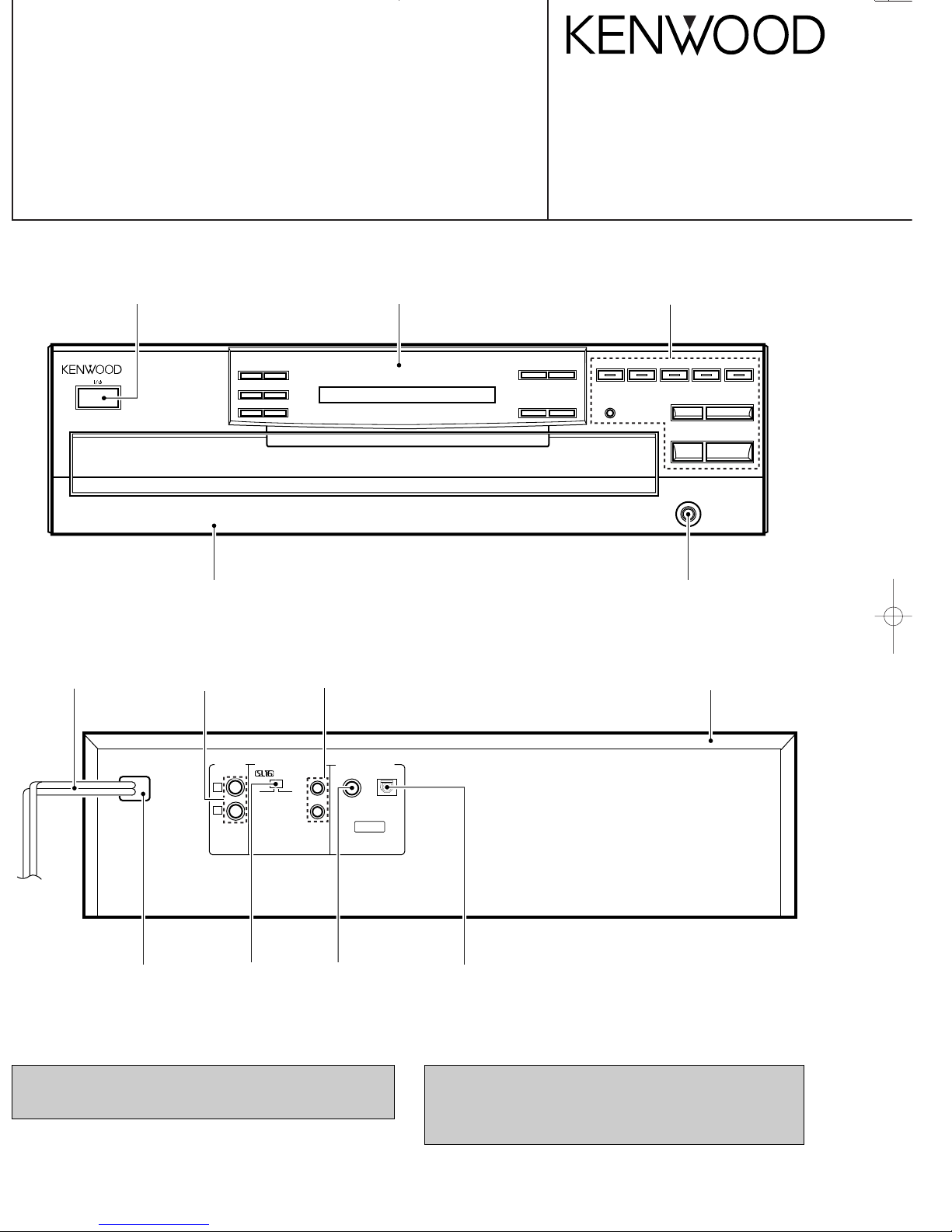
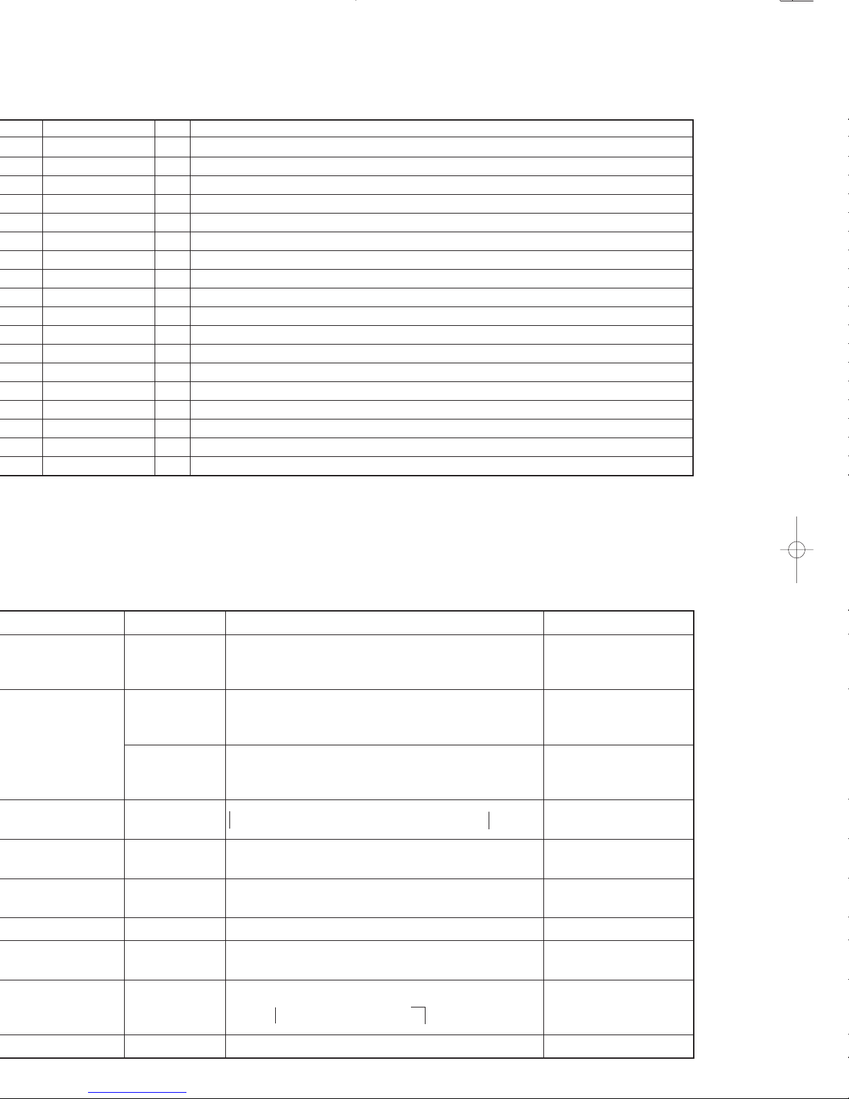
Panel*
(A60-)
Knob (POWER)*
(K27-)
AC power cord*
(E30-)
Miniature phone jack
(E11-0293-05)
Oscillating module
(W02-1114-05)
Phono jack
(E63-1009-05)
Slide switch
(S31-2132-05)
Phono jack
(E63-0199-05)
Metallic cabinet
(A01-3547-01)
Power cord bushing
(J42-0083-05)
Front glass
(B10-2466-03)
Knob assy*
(K29-)
Phone jack
(E11-0127-05)
* Refer to parts list on page 18 .
In compliance with Federal Regulations, following are reproductions of labels on, or inside the product relating to laser product
safety.
KENWOOD-Crop. certifies this equipment conforms to DHHS
Regulations No. 21 DFR 1040. 10, Chapter 1, Subchapter J.
DANGER : Laser radiation when open and interlock defeated.
AVOID DIRECT EXPOSURE TO BEAM
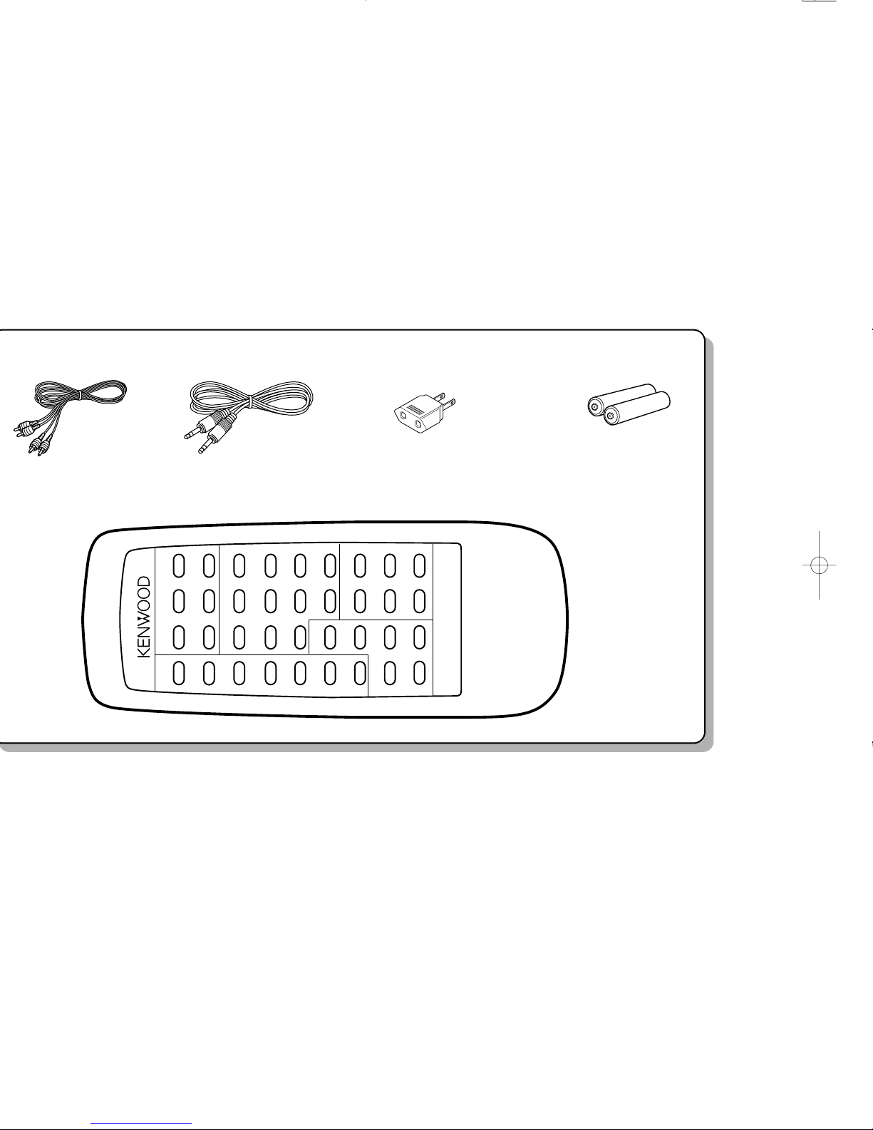
CONTENTS / ACCESSORIES
RANDOM
DISC SELECTOR
OUTPUT
1 2
3
4
5
REPEAT
DOWN UP
DISC SKIP
1 2
P.MODE
3
4 5
TIME
DISPLAY
6
EDIT 7 8
9
CHECK
TEXT
DISPLAY
0 +10
CLEAR ALL INFO.
6
ALL TEXT
SEARCH
TITLE
SEARCH
4
7
¡
¢
REMOTE CONTROL UNIT
RC-P0601
1
SCHEMATIC DIAGRAM........................................... 11
EXPLODED VIEW .................................................... 16
PARTS LIST.............................................................. 18
SPECIFICATIONS .......................................Back cover
Audio cord (1)
(E30-0505-05)
System control cord (1)
(E30-2733-05)
AC plug adapter (1)
(E03-0115-05) : M type only
Remote control unit (1)
(A70-1134-05) : RC-P0601
Batteries (R6/AA) (2)
Battery cover: (A09-0356-08)
CD-206/DPF-R6010/R6010E
3
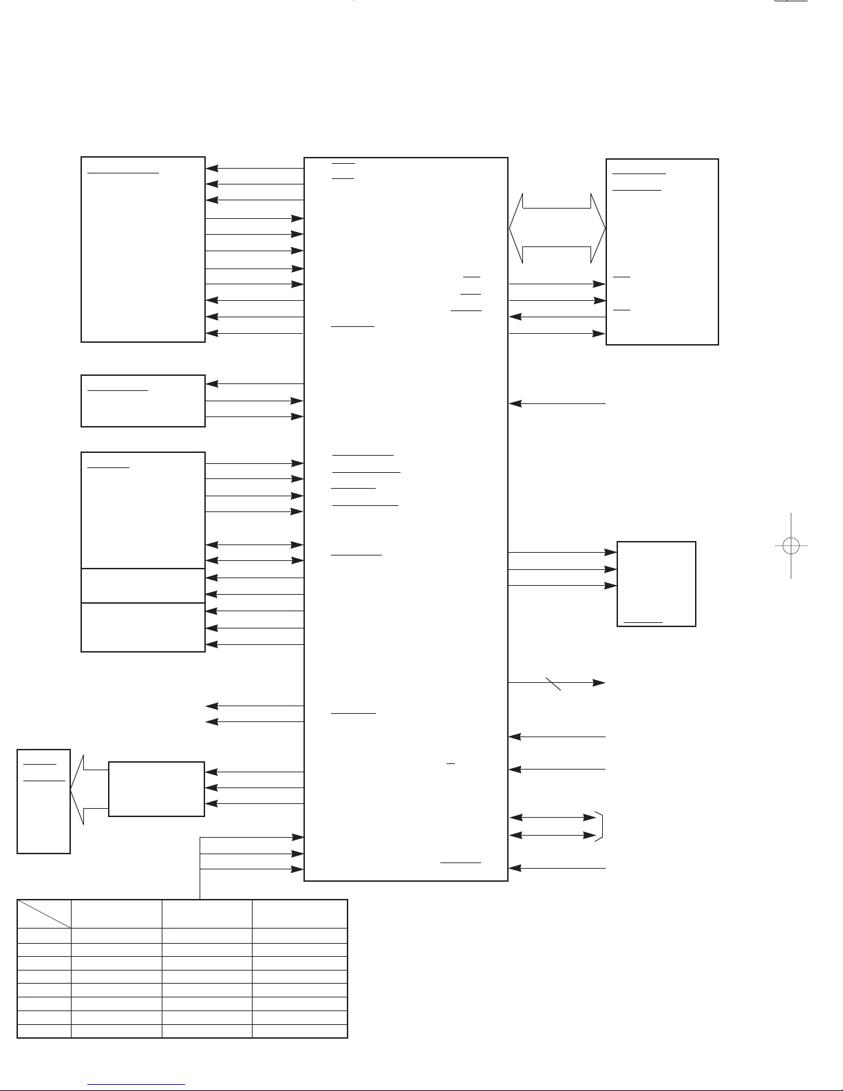
CIRCUIT DESCRIPTION
CDM25
MECHA SW
LOADING
DRIVER
ROTARY
DRIVER
1. Microprocessor : uPD78055GC-A03 (X32, IC3)
1-1 Microprocessor periphery block diagram
53 CLK
54 LAT
55 DATA 19~26
56 SENSE (AD0~AD7)
51 FOK 27~32
62 SCOR (A8~A13)
16 SUBQ
58 GFS RD 40
18 SQCK WR 41
52 MON WAIT 42
57 MUTEG ASTB 43
10 SCLK
8 SRDT
DEFECT 73
63 DQSY
uPD78055GC-A03
36 OPEN_SW
37 CLOSE_SW
38 UP_SW
39 DOWN_SW
49 DISC_SENS
48 POSI_SENS
44 SLT_SW
SGATE 64
34 OPENM
SCK 65
35 CLOSEM
SDATE 66
45 R_TRAY_S
46 R_TRAY_R
47 R_TRAY_L
67,80,1~3
LED1~5
50 LDC
59 RMUTE
REM 61
12 DATA 8/16bit 15
13 CLK
14 CE
SDATA 5
77 A/D KEY0 SBUSY 6
78 A/D KEY1
79 A/D KEY2 RESET 60
CXD2507AQ
CLK
(DSP) XLT
DATA
SENS
FOK
SCOR
SQSO
GFS
SQCK
MON
MUTE
X32, IC3
X32, IC2
LC89710M SCLK
(CD TEXT) SRDT
DQSY
X32, IC6
HM62256
BLFP 8T
(SRAM)
OR
W242575-70LL
/TC74HC373AF
(D-LATCH)
OE
WE
CE
LE
X32, IC7
SGATE
SCK
SDATA
KAN03
LASER ON / OFF
ANALOG METE
LC75710
(DOT DRIVER)
FIP15
XM1BA
(FL)
REMOCON
DEFECT NG
X32, IC4, IC5
X25, IC1
8bit/16bit
SERIAL
COMMUNICATION
RESET
PORT
(V)
A/D KEY0 (77PIN) A/D KEY1 (78PIN) A/D KEY2 (79PIN)
4.9 ~ 4.4 UP DISC1 TEXT DISPLAY
4.4 ~ 3.8 DOWN DISC2 ALL INFO.
3.8 ~ 3.2 FF DISC3 P. MODE
3.2 ~ 2.5 FB DISC4 TIME DISPLAY
2.5 ~ 1.9 EDIT DISC5 RANDOM
1.9 ~ 1.3 DISC SKIP OPEN/CLOSE REPEAT
1.3 ~ 0.6 – PLAY/PAUSE –
0.6 ~ 0.2 – STOP –
KEY TABLE
LED1 ~ 5
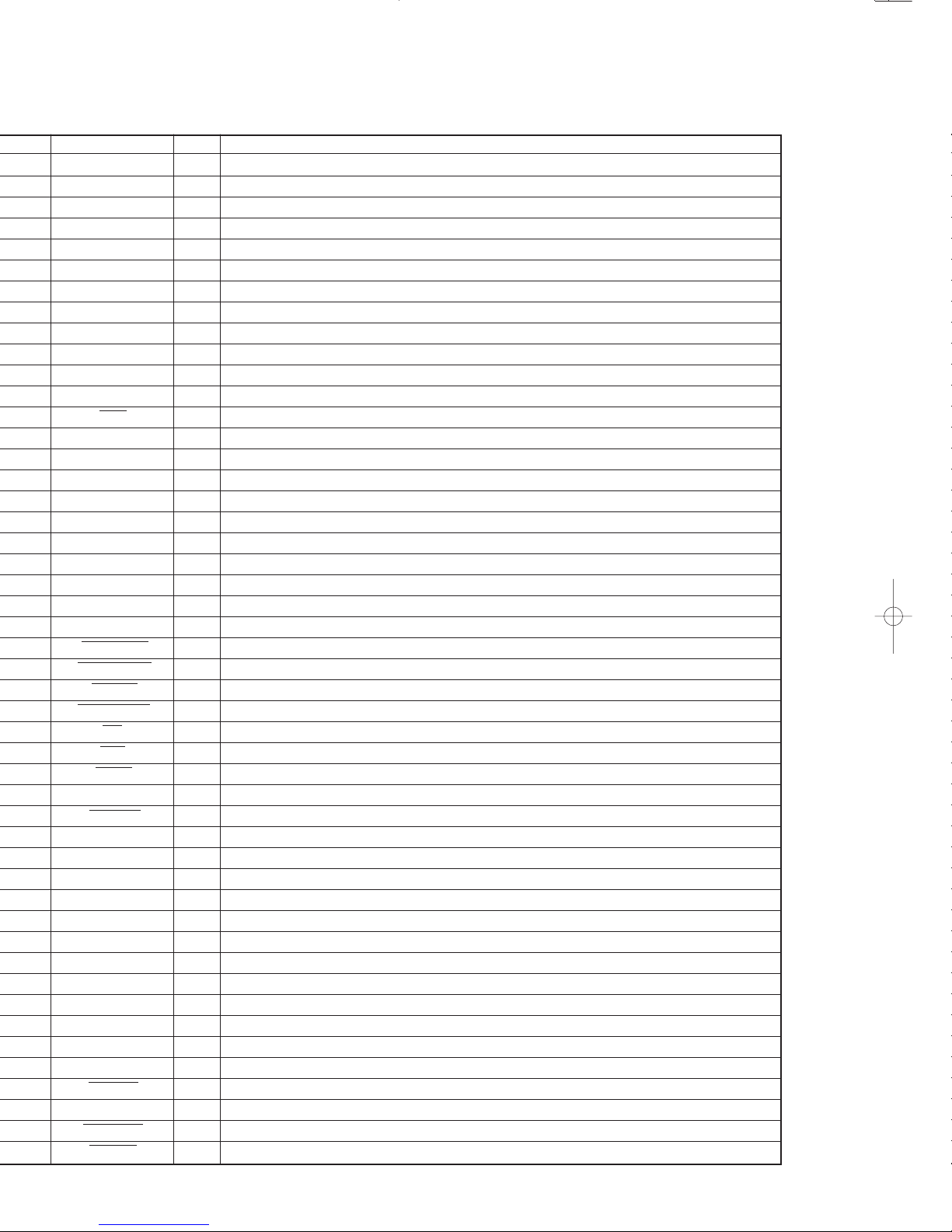
CIRCUIT DESCRIPTION
1 LED3 O DISC3 IN/OUT. H : LED lights-ON (Disc IN)
2 LED4 O DISC4 IN/OUT. H : LED lights-ON (Disc IN)
3 LED5 O DISC5 IN/OUT. H : LED lights-ON (Disc IN)
4 AVss – Vss (GND).
5 S.DATA I/O Serial DATA signal input/output.
6 S.BUSY I/O Serial BUSY signal input/output.
7 AVref1 I Vdd (+5V).
8 SRDT I LC89710M (CD TEXT decoder) DATA input.
9 NC O No used.
10 SCLK O LC89710M (CD TEXT decoder) CLOCK output.
11 STANDBY O No used. H : LED lights-ON
12 DATA O LC75710 (DOT driver) DATA output.
13 CLK O LC75710 (DOT driver) CLOCK output.
14 CE O LC75710 (DOT driver) CE output .
15 8/16bit I 8bit/16bit change-over. H : 16bit
16 SUBQ I Q data input.
17 NC O No used.
18 SQCK O Q data CLOCK output.
19-26 AD0 - AD7 I/O HM62256BLFP12T (SRAM) ADR/DATA input/output.
27-32 A8 - A13 O HM62256BLFP12T (SRAM) ADRESS output.
33 Vss – GND.
34 OPEN MOTOR O Tray motor control [OPEN]. H : OPEN/T.U.DOWN
35 CLOSE MOTOR O Tray motor control [CLOSE]. H : CLOSE/T.U.UP
36 OPEN SW I Tray open SW input. L : OPEN
37 CLOSE SW I Tray closure SW input. L : Closure
38 UP SW I Mechanism up SW input. L : UP
39 DOWN SW I Mechanism down SW input. L : Down
40 RD O Read strobe signal output.
41 WR O Write strobe signal output.
42 WAIT I External waiting signal input (No used).
43 ASTB O Address strobe signal output.
44 SLT SW I Start limit SW input.
45 R_TRAY_S O Rotary tray motor control. L : Deceleration
46 R_TRAY_R O Rotary tray motor control. H : CCW
47 R_TRAY_L O Rotary tray motor control. H : CW
48 DISC_SENSE I Disc sensor. H : Disc-IN
49 POSI_SENSE I Position sensor. L : Detection position
50 LDC O Laser signal output. L : Laser diode ON
51 FOK I F. OK input from CXD2507AQ.
52 MON O Spindle motor ON/OFF change-over to CXD2507AQ.
53 CLK O CLOCK output to CXD2507AQ.
55 DATA O DATA output to CXD2507AQ.
56 SENSE I SENSE input from CXD2507AQ.
57 MUTEG O Digital mute control.
58 GFS I GFS input from CXD2507AQ.
59 RMUTEG O Analog mute control.
60 RESET I Reset input.
5
CIRCUIT DESCRIPTION
CD-206/DFP-R6010/R6010E
61 REM I Remocon signal input.
62 SCOR I Sub code frame sync detection signal.
63 DQSY I Text data reading permission signal input.
64 SGATE O DATA output to KAN03.
65 SCK O CLOCK output to KAN03.
66 SDATA O Enable output to KAN03.
67 LED1 O DISC1 IN/OUT. H : LED lights-ON (Disc IN)
68 Vdd – Power supply (+5V).
69 X2 – System clock input.
70 X1 I System clock input.
71 IC – GND.
72 XT2 – No used.
73 GND – GND.
74 AVdd – Vdd.
75 AVref0 I Vdd.
76 A3 – No used
80 LED2 O DISC2 IN/OUT. H : LED lights-ON
MODE by just pressing the RANDOM key when set to
power on.
keys Display Description Remarks
8 03 || :||
Setting the test mode
8 03 || :||
(1) Focus servo – – – – ON
(2) Tracking servo – – OFF
(3) Feed servo – – – – OFF
TE-balance adjustment
‰ 05 00 : 00
(1) Focus servo – – – – ON
(2) Tracking servo – – – ON
(3) Feed servo – – – – – ON
Focus gain / Tracking
gain and FE-balance
adjustment
î FL all light up î dot demonstration mode ì
ììì
normal test mode indication нмммм
FEED OUT
Move the pick-up to the direction of the outer circumference.
FEED IN
Move the pick-up to the direction of the inner circumference.
TEST 00 Disc will be stopped.
8 BIT SYNC
16 BIT SYNC
8 bit sync and 16 bit sync will be displayed by changing
the SL16/XS8 switch on the rear panel.
Change the output level cyclically.
ì Max î -10dB î Min
ммммммнммммм
Cancellation of the test mode and 01 play.
6
ADJUSTMENT
CD-206/DPF-R6010/R6010E
FIG.
GND
+
_
L.P.F.
+
+
L.P.F.
VTVM
VTVM
1
2
3
4
5
6
7
1.2 kHz
50 mVrms
(a)
No. ITEM
INPUT
SETTINGS
OUTPUT
SETTINGS
ALIGNMENT
POINTS
ALIGN
FOR
PLAYER
SETTINGS
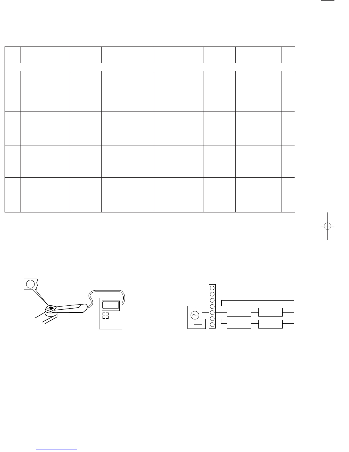
1 LASER POWER
−
Apply the sensor section
of optical power meter
on the pickup lens.
−
On the power from
0.08 to 0.15 mW,
when the diffraction
grating is correctly
aligned with the RF
level of 1.0 Vp-p or
more.
While pressing the
RANDOM key, turn
the AC ON. (Test
mode) Press the
PLAY/PAUSE key,
then confirm that the
display is "03".
(a) Laser power
Pickup
3
FOCUS ERROR
BALANCE
Test disc
Type 4
Connect an oscilloscope
as follows.
CH1 : RF (CN2 pin 1)
CH2 : FE (CN2 pin 2)
FE BALANCE
VR1
Optimum eye pat-
tern
Press the
PLAY
/PAUSE
key,
then confirm that the
display is "05".
Note:
Type 4 disc : SONY YEDS-18 Test Disc or equivalent.
LPF: Around 47 kΩ+ 390 pF or so.
0.08~0.15 mW
Optical power meter
2
TRACKING ERROR
BALANCE
Test disc
Type 4
Connect an oscilloscope
as follows.
CH1 : RF (CN2 pin 1)
CH2 : TE (CN2 pin 6)
TE BALANCE
VR2
Symmetry between
upper and lower pat-
terns
Press the
PLAY/PAUSE key,
then confirm that the
display is "03".
CN2
(e) Tracking gain
(e)
4
TRACKING GAIN
Test disc
Type 4
Apply signal of
1.2 kHz,
50mVrms to
CN2 pin 5-6.
Connect a LPF to CN2
pin 5-6 to which you
connect an oscilloscope
or AC voltmeters.
TRACKING
GAIN
VR3
Two VTVMs should
read the same
value.
Press the
PLAY/PAUSE key,
then confirm that the
display is "05".
Step 1~4 are in TEST MODE
 Loading...