Mode Sensitivity: AM mode less than 25 nV to less than 2 nV With variation in frequency range. FM mode always less than 0.5 nV and less than 0.5 μV,
Notch Filter Attenuation: Requires to be over 25 dB at frequencies more than 500 to 2600 Hz, Squelch Sensitivity: Needs to be lower than or equivalent 20 μV but less than 2 μV varies mode and frequency range,
Intermediate Frequency for AM/USB/LSB/CW/FSK: The first is 58.1125 MHz and the second is 8.83 MHz. For FM the first is still 58.1125, the second remains the same while the third is 455 kHz.
IF Shift: Must maintain a variable range of greater than +0.9 kHz.
Selectivity for AM: Fifty in benchmark decibels at a mark of twenty kilohertz while twenty six negative fifty at twenty five kilohertz is FM.
Image Ratio: More than sixty decibels while depending on frequency range.
Notch filter attenuation: For 500 to 2600 Hz over twenty five Decibels.
squelch sensitivity: From twenty microvolts and above with a mark of twenty microvolts dependent on the mode and the frequency range.
Squelch sensitivity: Less than +10 PPM
Power Requirement: 240/220/120V AC, 249 V, or 15V DC
Power Consumption: 40 Watts (AC), 2 A (DC)
Operating Temperature: -10 to +50° Celsius
Dimensions: 270 x 270 x 96 mm (projection 279 x 107 x 307 mm)
Weight: 5.6 KG (12.3 lbs)
Frequently Asked Questions
Q1: What power supply does the R-5000 require?
A1: This unit is restricted to a power supply of 120 AC V if located in Canada and U.S.A, in other regions a 120, 220 and 240 AC V power supply will work depending on where the switch for power supply is placed.
Q2: Can I use this Receiver for FM transmission?
A2: Any radio frequency transmission along with FM transmissions can be received by the R-5000, other modes which this device is capable of receiving includes AM, USB, LSB, FSK and CW
Q3: Which antenna is ideal for the R-5000?
A3: As for ANT 1, you can connect a 50 ohm low impedance antenna and ANT 2 can connect to 50/500 ohm low or high impedance antenna. Outdoor antennas would provide the best reception.
Q4: Can you store channels in the R-5000?
A4: Yes, the R-5000 P has the capability to save up to 100 saved channels with the use of a memory function that allows a person to recall the channels by them being organised into groups.
Q5: At what temperature do you suggest the R-5000 is operated at?
A5: Keeping the receiver out of harsh low temperatures, moisture and extreme heat, the optimal temperature for the device would be anywhere above 5 degrees celsius.
Q6: How do I delete a memory channel?
A6: To delete a memory channel you must go to the Memory Channel mode, select which channel you wish to delete, and while holding the CLEAR key press the ENT key.
Q7: In the case of the R-5000 running out of charge, would there be a backup system?
A7: The R-5000 runs on rechargeable batteries which would allow the device to run for 10 days when unplugged from AC whilst chargind when in use.
Q8: What steps do I take when the radio does not power up?
A8: Begin by inspecting the power cord and the connecting wires, and then ascertain that both the power supply and fuse are fully functional. If all fails, please make sure the TIMER switch is turned off.
U.S.A. and Canada
Units shipped to the U.S.A. and Canada are designed
for operation on 120 volts AC only. These units are not
equipped with an AC voltage selector switch and the
discussion of such a switch that follows should be
disregarded.
All other countries
Units shipped to countries other than the U.S.A., Canada are equipped with an AC voltage selector switch on
the rear panel. Refer to the following paragraph for the
proper setting of this switch.
AC voltage selection
This unit operates on 120 volts, 220 volts or 240 volts
AC. The AC voltage selector switch on the rear panel is
set to the voltage that prevails in the area to which the unit
is shipped. Before connecting the power cord to your AC
outlet, make sure that the setting position of this switch
matches your line voltage. If not, it must be set to your
voltage in accordance with the following direction.
Note:
Our warranty does not cover damage caused by excessive
line voltage due to improper setting of the AC voltage selector switch.
Before plugging in this unit, make sure that the position
of the AC voltage selector conforms to your line (mains)
voltage. If not, it must be reset.
AC voltage selector switch
For United Kingdom
be removed from the wall
The mains plug
prior to any internal examination.
Warning:
This apparatus must be earthed.
must
socket
Important
The wires in this mains lead are coloured in accordance
with the following code:
Neutral
Live
Earth
Blue
Brown
Green-and-yellow
The wires in this mains lead must be connected to the
terminals in the plug as follows:
WARNING:
TO PREVENT FIRE OR ELECTRIC SHOCK, DO
NOT EXPOSE THIS APPLIANCE TO RAIN OR
MOISTURE.
Safety precautions
CAUTION: TO REDUCE THE RISK OF ELECTRIC SHOCK, DO NOT REMOVE COVER
(OR BACK). NO USER-SERVICEABLE PARTS INSIDE. REFER SERVICING TO QUALIFIED SERVICE PERSONNEL.
The lightning flash with arrowhead symbol, within an equilateral triangle, is intended
to alert the user of the presence of uninsulated "dangerous voltage" within the product's enclosure; that may be of sufficient magnitude to constitute a risk of electric
shock to persons.
The exclamation point within an equilateral triangle is intended to alert the user of
the presence of important operating and maintenance (servicing) instructions in the
literature accompanying the appliance.
2
Notes:
1)
2)
If a 13-amp plug is used, this must be fitted with a
3-amp fuse.
If a 3-pin plug with earthing contact is used, no wire
must be connected to the E terminal.
Page 3
SAFETY INSTRUCTIONS
1.
Read Instructions — All the safety and operating instructions should be read before the appliance is operated.
2. Retain Instructions — The safety and operating instructions should be retained for future reference.
Heed Warnings — All warnings on the appliance and in
3.
the operating instructions should be adhered to.
4.
Follow Instructions — All operating and use instructions should be followed.
5.
Water and Moisture — The appliance should not be
used near water — for example, near a bathtub, washbowl, kitchen sink, laundry tub, in a wet basement, or
near a swimming pool, and the like.
6.
Wall or Ceiling Mounting — The appliance should be
mounted to a wall or ceiling only as recommended by
the manufacturer.
7.
Ventilation — The appliance should be situated so that
its location or position does not interfere with its
proper ventilation. For example, the appliance should
not be situated on a bed, soft, rug, or similar surface
that may block the ventilation openings; or, placed in
a built-in installation, such as a bookcase or cabinet
that may impede the flow of air through the ventilation openings.
8.
Heat — The appliance should be situated away from
heat sources such as radiators, heat registers, stoves,
or other appliances (including amplifiers) that produce
heat.
12. Protective Attachment Plug — The optional DC operation kit is supplied with an attachment plug having
overload protection. This is a safety feature. See Instruction Manual for replacement or resetting of protective device. If replacement of the plug is required,
be sure the service technician has used a replacement
plug specified by the manufacturer that has the same
overload protection as the original plug.
13. Cleaning — The appliance should be cleaned only as
recommended by the manufacturer.
14. Power Lines — An outdoor antenna should be located
away from power lines.
15. Outdoor Antenna Grounding — If an outside antenna is
connected to the receiver, be sure the antenna system
is grounded so as to provide some protection against
voltage surges and built up static charges. Section
810 of the National Electrical Code, ANSI/NFPA No.
70-1984, provides information with respect to proper grounding of the mast and supporting structure,
grounding of the lead-in wire to an antenna discharge
unit, size of grounding conductors, location of antenna-discharge unit, connection to grounding electrodes, and requirements for the grounding electrode.
See accompanying Figure.
16. Nonuse Periods — The power cord of the appliance
should be unplugged from the outlet when left unused
for a long period of time.
17. Object and Liquid Entry — Care should be taken so that
objects do not fall and liquids are not spilled into the
enclosure through opening.
9.
Power Sources — The appliance should be connected
to a power supply only of the type described in the
operating instructions or as marked on the appliance.
10.
Grounding or Polarization — The precautions that
should be taken so that the grounding or polarization
means of an appliance is not defeated.
11.
Power-Cord Protection — Power-supply cords should
be routed so that they are not likely to be walked on or
pinched by items placed upon or against them, paying
particular attention to cords at plugs, convenience receptacles, and the point where they exit from the appliance.
18. Damage Requiring Service — The appliance should be
serviced by qualified service personnel when:
A.
The power-supply cord or the plug has been damaged; or
B.
Objects have fallen, or liquid has been spilled into
the appliance; or
C.
The appliance has been exposed to rain; or
D.
The appliance does not appear to operate normally
or exhibits a marked change in performance; or
E.
The appliance has been dropped, or the enclosure
damaged.
19. Servicing — The user should not attempt to service the
appliance beyond that described in the operating instructions. All other servicing should be referred to
qualified service personnel.
3
Page 4
EXAMPLE OF ANTENNA GROUNDING ACCORDING
TO NATIONAL ELECTRICAL CODE INSTRUCTIONS
CONTAINED IN ARTICLE 810 –"RADIO AND
TELEVISION EQUIPMENT"
) copper. No. 8 AWG (8.4 mm2) alu-
Use No. 10 AWG (5.3 mm
a
minuet, No. 17 AWG (1.0 mm
2
2
) copper-clad steel or bronze
wire, or larger,as a ground wire.
Secure antenna lead-in and ground wires to house with stand-
b
off insulators spaced from 4 – 6 feet (1.22 –1.83 m) apart.
4
C
Mount antenna discharge unit as close as possible to where
lead-in enters house.
Use jumper wire not smaller than No. 6 AWG (13.3 mm/) cop-
d
per, or the equivalent, when a separate antenna-grounding electride is used. See NEC section810-21(j).
Page 5
Before operation
Safety precautions
Never remove the case. If the internal parts are touched
accidentally, a serious electric shock might occur.
Where to install the unit
Do not place the unit near a heat producing equipment
such as a radiator. Avoid direct sunlight.
If a metal object, such as a hair pin or a needle, comes into
contact with the power socket on the rear panel, a dangerous electric shock may result. For families with children,
never permit children to put anything, especially metal, inside this unit.
Touching the power plug when your hands are wet may
result in a serious electric shock.
Do not store or use the unit in a dusty location or in a
moist atmosphere. Select a location where air is well ventilated.
Install the unit approx. 10 cm (or 4 inches) away from the
wall, for heat dissipation.
Install the unit on a flat, vibration-free rigid table.
Never pull, bend or extend the power cord. This could damage the power cord, resulting in a broken cord or shortcircuit.
The unit may not function properly if used at extremely
low, or freezing temperatures. The ideal ambient temperature is above +5°C (41°F).
5
Page 6
Thank you for purchasing the new R-5000 Communications Receiver. Please read this Instruction Manual carefully before
placing your receiver in service. This unit has been carefully engineered and manufactured to rigid quality standards, should
give you satisfactory and dependable operation for many years.
CONTENTS
MAINTENANCE
SAFETY
1.
SPECIFICATIONS AND ACCESSORIES
2.
2-1. SPECIFICATIONS
2-2. ACCESSORIES
INSTALLATION AND CONNECTION
3.
3-1. INSTALLATION
3-2. CONNECTION
OPERATION
4.
4-1. CONTROL FUNCTIONS
4-2. RECEIVE
4-3. MEMORY
4-4. SCAN
4-5. CLOCK AND TIMER
Caution:
Optional accessory installation – The user should not attempt to install the optional accessory beyond that described in the
operating instructions. All installtions should be referred to qualified service personnel.
Note:
Illustrations show the R-5000 U.S.A. version unless specified in this Instruction Manual.
2
7
7
8
9
9
9
12
12
18
21
23
25
5.
5-1. GENERAL INFORMATION
5-2. SERVICE
5-3. CLEANING
5-4. IN CASE OF DIFFICULTY
OPTIONAL ACCESSORIES
6.
REFERENCES
7.
7-1. ENJOYING SW RECEPTION
7-2. ANTENNA AND GROUNDING
BLOCK DIAGRAM AND CIRCUIT DIAGRAM ,
8.
8-1. BLOCK DIAGRAM
8-2. CIRCUIT DIAGRAM
27
27
27
27
28
29
30
30
32
34
34
35
6
Page 7
2. SPECIFICATIONS AND ACCESSORIES
Scanned by Vincent
Downloaded by
RadioAmateur.EU
2-1. SPECIFICATIONS
Specifications
Circuitry
Antenna
impedance
Frequency range *1
Intermediate
frequency
Mode
Sensitivity
Mode
USB/LSB/CW/FSK
(at 10 dB S + N/N)
AM
(at 1 kHz 30% mod.)
FM
(at 12 dB SINAD)
Model
AM/USB/LSB/
CW/FSK
FM
ANT 1
ANT 2
AM/USB/LSB/
CW/FSK
FM
Frequency range
100 to 150 kHz 150 to 500 kHz
Less than 2.5 µV
Less than 25 µV
-
U.S.A. version
Less than 1 µV
Less than 10 pV
-
R-5000
Europe, U.K. and
other market
versions
Australia
version
West Germany
version
Double conversion superheterodyne
Triple conversion superheterodyne
50 ohms
50/500 ohms
100 kHz to 30 MHz
108 to 174 MHz
2 to 30 MHz
108 to 174 MHz
150 kHz to
26.2
144 to 146 MHz
1st: 58.1125 MHz, 2nd: 8.83 MHz
1st: 58.1125 MHz, 2nd: 8.83 MHz, 3rd: 455 kHz
AM(A3E)/USB(J3E)/LSB(J3E)/CW(A1 A)/FM(F3E)/FSK(F1 B)
500 kHz to 1.8 MHz
Less than 4 µV
Less than 32V
µ
-
1.8 to 30 MHz
Less than 0.25 µV
V
Less than 2
Less than 0.5 µV
108 to 123 MHz * 1
Less than 0.5
Less than 4
Less than 1 µV
V
µ
123 to 174 MHz *1
Less than 0.25 µV
Less than 2 µV
Less than 0.5 pV
MHz
µ
Selectivity
Image ratio
1
st IF rejection
IF SHIFT variable range
NOTCH filter attenuation
Squelch
sensitivity
Mode
AM/USB/LSB/CW/FSK
FM
Frequency range
100 to 150 kHz
Less than 20 µV
- -
100 kHz to 1.8 MHz
More than 60 dB
100 kHz to 1.8 MHz
More than 60 dB
150 to 500 kHz
Less than 10µV
USB/LSB/CW/FSK
AM
FM
More than 25 dB (500 to 2600 Hz)
500 kHz to
1.8 MHz
Less than 20 pV
-
1.8 to 30 MHz
More than 80 dB
1.8 to 30 MHz
More than 80 dB
More than ± 0.9 kHz
1.8 to 30 MHz
Less than 2 µV
Less than 0.32 µV
-6 dB
-60 dB
-6 dB
-50 dB
-6 dB
-50 dB
108 to 123 MHz *1
More than 40 dBMore than 50 dB
108 to 123 MHz*1
More than 70 dB
108 to 123 MHz *1
Less than 10 µVLess than 2 pV
Less than 1 µV
2.4 kHz
4.4 kHz
6 kHz
20 kHz
12 kHz
25 kHz
123 to 174 MHz *1
123 to 174 MHz*1
More than 80 dB
123 to 174 MHz *1
Less than 0.32 pV
7
Page 8
Frequency accuracy
Scanned by Vincent
Downloaded by
RadioAmateur.EU
Less than ± 10 PPM
Frequency stability
EXT. speaker
Output
Output load impedance
Clock
Power requirement *2
Power consumption
Operating temperature
Dimensions. W x H x D
(
) includes projection.
Weight
Notes:
2.
3.
1.
*1: The optional VC-20 VHF Converter Unit is required for the VHF reception.
*2: The optional DCK-2 DC Operation Kit is required for the DC Operation.
Circuit and ratings are subject to change without notice due to advancements in technology.
REC jack
Type
Accuracy
120 VAC ± 10%,
60 Hz or
13.8 VDC ±15%
1.5 W across 8 ohms load (10% distortion)
300 mV across 4.7 kΏ load (at 1 mV input with
30% mod. in AM or 3 kHz dev. in FM)
120/220/240 VAC ± 10%, 50/60 Hz or
13.8VDC ± 15%
Less than ± 10 PPM
8 ohms min.
Quartz clock
Less than ± 60 seconds/month
40 watts (AC) or 2 A (DC)
–10 to +50°C (+14 to +122°F)
270 x 96 x 270 mm
(279 x 107 x 307 mm)
5.6 kg (12.3 Ibs)
2-2. ACCESSORIES
Unpack your R-5000 carefully and confirm that it is supplied with the following accessories.
AC power cable (U.S.A. and Canada only)
AC power cable (Europe only)
AC power cable (Oceania only)
AC power cable (U.K. only)
AC power cable (Other markets only)
Instruction manual
Warranty card
Shipping container:
Save the boxes and packing in the event your unit needs to be transported for remote operation, maintenance, or service.
3-1-1. Bail
The receiver can be elevated for operating convenicence.
Caution:
Do not use the bail to carry the receiver.
A.
Power supply
Cautions:
1. The POWER switch must be OFF before you connect or disconnect the power cable.
2. Do not apply AC and DC power sources at the
same time.
(A) AC operation
When the R-5000 is to be operated from a fixed loca-
using normal household current you should connect the AC power cable that is supplied with the radio to the AC terminal on the rear panel.
(B)
DC operation (The optional DCK-2 DC Operation Kit is
required for this operation.)
The R-5000 can also be operated from a 12 volt automobile battery. Attach the power cable that is supplied with the DCK-2 DC Operation Kit to the cigarette
lighter socket in your vehicle.
Cautions:
1. The DCK-2 DC Operation Kit, should be installed by
qualified service personnel to prevent personal injury or
damage to the equipment.
2. When charging the battery or when jump starting a
dead battery you MUST disconnect the power cable
from the back of the radio, or serious damage may result to the
3. The clock and the timer function even if the POWER
switch is turned OFF. When the receiver is not in use,
unplug the cigarette lighter plug from the vehicle's cigarette lighter socket to prevent the battery from discharging.
radio
.
9
Page 10
B. Antenna and grounding
(A) Antenna
Installation of antenna and grounding is important for optimum reception of short-wave, broadcast or amateur radio
signals. A good outdoor antenna will provide the best results.
Caution:
Protect your Equipment
TOR.
Use a LIGHTNING ARRES-
VHF ANT connector (Optional VC-20 VHF Converter
is required for VHF reception.)
When an outdoor antenna is used the antenna feeder
should be a coaxial cable equipped with a UHF connector.
Caution:
The VC-20 VHF Converter Unit should be installed by qualified service personnel to prevent personal injury or da-
mage to the equipment.
Note:
A simple method is to install the wire antenna as high as
possible, it must be extended to its full length for good results.
ANT 1: UHF coaxial antenna connector
Use a low impedance antenna. The antenna
feeder should be a coaxial cable equipped with a
PL-259 connector.
ANT 2: 500-ohm antenna terminal
Connect a high impedance antenna such as a
long wire antenna.
50-ohm antenna terminai
Connect a low impedance antenna.
Note:
To connect both 500-ohm and 50-ohm antenna terminals
at the same time may cause the receiving sensitivity
worse.
C. External speaker
The R-5000 includes a built-in speaker.If you would like
to use an external speaker, such as the SP-430, it may be
connected to the EXT SP jack on the rear of the radio. The
speaker may be any good 8 ohm permanent magnet type
speaker.The diameter should be at least 4 inches for
(B) Grounding
Making a good earth connection is important for preventing dangers such as electric shock. Bury a commercially
available ground rod or copper plate under the ground and
connect it to the GND terminal. A thick wire, cut as short
as possible, should be used for the connection. To make a
good earth connection, connect the GND terminal to a
grounded metal water pipe.
Caution:
Never use a gas pipe or electrical conduit pipe.
Note:
A city water pipe cannot be used as a good earth in some
cases.
good audio quality.
than the SP-430 it should be equipped with a miniature
phone jack plug.
The internal speaker is disabled when the external speaker
plug is inserted into the receptacle.
If you plan on using a speaker other
A. Headphones
Any low-impedance (4 used with the R-5000. Connect the headphones to the
front-panel phone jack.
The optional HS-5 or HS-6 headphones are best suited for
use with the R-5000. Stereo type headphones can also be
used.
10
16 ohms) headphones may be
B. Tape recorder
This terminal may be used for recording broadcasts on
tape. Connect it to the LINE IN jack of your tape recorder.
The output level at this terminal is constant, regardless on
the AF gain control setting.
Page 11
3-2-3. Connecting the R-5000 with a transmitter or
transceiver
Ground the REMOTE connector pin (pin 7) to mute the
1.
R-5000 audio during transmission.
REMOTE connector
The open-circuit voltage at pin 7 is about +4.8 VDC;
the short circuit current is about 0.4 mA DC.
Connect the antenna to the R-5000 via the transmitter
2.
or transceiver antenna switching relay. If you are using
a receive-only antenna, disconnect it from the R-5000
while transmitting.
Cautions:
1.
Failure to disconnect the antenna from the R-5000
when transmitting on a seperate transmitter/
transceiver will result in damage to the R-5000.
Do not apply AC voltage to the REMOTE connector.
2.
11
Page 12
4. OPERATION
Scanned by Vincent
Downloaded by
RadioAmateur.EU
4-1. CONTROL FUNCTIONS
4-1-1. Front panel
Note:
All segments on the Display Panel and Indicators are shown on for this explanation.
POWER switch
C)
Press to turn the power ON or OFF.
Note:
When the AC or DC power cable is connected the clock
and the timer function even if the POWER switch is turned
OFF.
® Meter
Indicates signal strength in S units and antenna terminal
input voltage.
MODE/KEY (Numeric Keypad)
®
These keys are used to select the desired mode of operation and the antenna.
LSB : Lower Sideband
USB : Upper Sideband
CW : Continuous Wave
AM : Amplitude Modulation
: Frequency Modulation
FM
FSK : Frequency Shift Keying
ANT
1:
Antenna 1
ANT 2 : Antenna 2
When programming a memory channel or directly entering
a frequency these keys are used as a numeric keypad to
enter the channel number or frequency. FM mode is suitable for the narrow band FM (maximum frequency deviation: ± 5kHz) reception.
® Indicators
F.LOCK : Lights when the F.LOCK key is ON.
NOTCH : Lights when the NOTCH key is ON.
ANT 2
ANT 1
M.SCR : Lights when the M.IN key is pressed. When
BUSY : Lights when the squelch opens. (A signal
®
Display Panel
The fluorescent display tube displays operational
such as receive frequency, and memory channel
tion
mation.
Lights when the ANT 2 key is pressed.
: Lights when the ANT 1 key is pressed.
the memory scroll function is active you can
review the contents of the memory channels
without a loss of the incoming receive frequency.
received that is strong enough to produce a
good quality audio output.)
(See page 15.)
® FUNCTION keys
HOUR: See page 25.
MINUTE : See page 25.
A/B
FLOCK : The selected dial frequency and mode are
STEP
A = B
: Selects VFO A or VFO B. (See page 19.)
locked.
: Selects the VFO frequency step. (See page
19.)
: Equalizes the frequencies and modes of VFO
A and VFO B. (See page 19.)
is
informa-
infor-
12
Page 13
known as the squelch threshold point. Now you will only
hear output from the speaker when an incomming signal is
present. For weak signal reception this control should be
fully counterclockwise.
Note:
The squelch threshold position will vary from mode to
mode, so you may have to readjust when you change
mode.
®
NOTCH control
The NOTCH function is used to reduce or eliminate heterodyne, or CW type signal interference.
If a single tone such as a CW signal is superimposed on
the receive signal, turn the NOTCH switch ON and slowly
adjust the NOTCH control to eliminate or minimize the
beat signal. Normally the NOTCH point will occur between
11:00 and 1:00.
The NOTCH filter will not be effective against SSB, AM or
FM type signals, only single tone CW type signals.
In the CW mode, an audio peak filter (APF) is automatically
selected; adjust the NOTCH control for the best signal.
In CW, we recommend the use of a CW filter (YK-88C or
YK-88CN). When a CW filter is installed, the APF is dis-
connected.
Whithout a CW filter installed, APF is connected in CW
mode. The APF works in similar fashion as a CW filter.
Note:
The NOTCH function is used to reduce or eliminate heterodyne, or CW type signals.
J SELECTIVITY switch
When an optional filter is installed, the receiver's passband
be switched to one of four different bandwidths by us-
can
ing the SELECTIVITY switch.
switch has five positions; AUTO, N, M 1, M2 and W,
The
are used to select the bandwidth. This switch should
that
normally be set to the AUTO position. The IF bandwidth
will then be selected for optimum receiver characteristics,
according to the MODE that has been selected. Manual
override is possible by simple rotation of the SELECTIVITY
switch.
The table on page 16 shows the bandwidth of each switch
setting. Note the differences when the optional filters are
installed.
Caution:
Optional filter should be installed by qualified service personnel to prevent personal injury or damage to the equipment.
Note:
When in the FM mode the bandwidth is always 12kHz, regardless of the position of the SELECTIVITY switch.
®
This control is used to eliminate atmospheric noise, and
receiver static noise during no signal periods. Slowly rotate the control clockwise to the point where the ambient
noise just disappears, and speaker shuts off. This point is
SQL (Squelch) control
I F SH I FT control
®
The IF SHIFT control allows you to shift the IF passband of
the receiver, without changing the actual center frequency
of the receiver. This control is useful when there is interference near your center frequency.
Interference from lower frequencies can be reduced or eliminated by rotating the IF SHIFT control clockwise. This
will cause the resulting audio frequencies to have a slightly
treble response, i.e. low cut filter (low frequencies attenuated). Interference from higher frequencies can be reduced or eliminated by rotating the IF SHIFT control
counterclockwise. This will cause the resulting audio frequencies to sound a little bassy, i.e. high cut filter (high frequencies attenuated).
Note:
The IF SHIFT control does not function in the AM or FM
modes.
13
Page 14
11
RF gain control
This control adjusts the gain of the receiver high-
frequency amplifier section.
rf
For normal receiver pe
control should be in the full clockwise position. If you are
having trouble copying the desired signal make a note of
the stations peak S-meter reading. Then, adjust the RF
control counterclockwise, so that the meter needle is stationary at this level. Now, all signals that were less than
the desired signal will be attenuated, such as static noise,
etc., making reception easier.
If the incoming signal pegs the S-meter you can also reduce the receiver gain by counterclockwise rotation of the
RF control. The S-meter pointer will always advance upscale as the RF control is rotated counterclockwise, as a
visual reminder that the gain of the radio has been reduced.
Simultaneous use of the RF gain control and AGC
switch
If a strong signal (such as a local station) appears in the vicinity of the intended receive signal, the S-meter may
show unusual deflection due to the AGC voltage developed from the strong disturbing signal. If this occurs, turn
the RF gain control counterclockwise so the meter pointer
remains at about the original deflection peak and turn the
AGC switch to the FAST position. This will reduce the unwanted AGC voltage and permit clear reception.
12
AF gain control
Turn the knob to increase or decrease the volume.
Clockwise rotation increases the volume and counterclockwise rotation decreases the volume.
ormance, and maximum gain, this
nal, thereby stabilizing the receiver performance. This is
easily done by activating the RF ATT switch. This control
is also useful when a strong signal is near your desired signal; while some loss will occur to the desired signal, as
well as the undesired signal, the use of the attenuator will
sometimes allow you to understand what is being received. This switch allows attenuation of the input signal
rf
by 10, 20 or 30 dB. For normal receiver pe
switch should be in the 0 dB position.
Note:
When using the VC-20 VHF converter you might occasionally encounter carrier interference from
FM broadcast stations. If you encounter any
terference rotate the RF ATT switch to the 10 dB position.
This will help to reduce any cross modulation that might
occur due to the strength of these types of signals.
14
AGC switch
This switch selects the operating time
AGC (Automatic Gain Control) circuit.
switch is set to SLOW, the receiver gain and S-
When the NOTCH switch is turned ON, the NOTCH control
functions as a NOTCH filter (except in the CW mode). In
the CW mode, the NOTCH control functions as an APF
(Audio Peak Filter).
®
NB 2 switch
Noise blanker 2 is used for long duration pulse noise, like
the "woodpecker-. To reduce "woodpecker" radar noise
interference, set switch NB 2 to the ON position (NB 2's
effectiveness depends on the specific type of interference). If you use NB 2 for short duration pulse noise, the
receive tone may become distorted, making it difficult to
hear.
Unfortunately no noise blanker can remove all different
types of interference, but the two noise blankers that have
been provided in the R-5000 are effective in most cases.
If there is no "woodpecker" present, the switch should be
in the OFF position.
Note:
NB2 is disabled during FM operations.
or
in-
to
13
RF ATT (Attenuator) switch
When the incoming receive signal is very strong, the signal should be attenuated to prevent distortion of the sig-
14
1]
NB 1 switch
For pulse type noise, such as generated by automotive ig-
nition systems, turn the NB 1 switch ON.
Page 15
When pulsating noise, such as that caused by automobile
ignitions is encountered, place the NB 1 switch ON.
This switch will not help to eliminate atomospheric or line
noises, only pulse type noise.
Note:
NB 1 is disabled during FM operations.
NB level control
18
Controls the noise blanker operating level.
Use only the minimum level necessary.
19 1
MHz (UP/DOWN) key
Increases (UP) or decreases (DOWN) the displayed frequency in 1 MHz steps, throughout the entire frequency
range of the receiver. Pressing and holding either key will
cause the frequency to continuouslly step up or down as
long as the key is held depressed.
20 HF/VHF key
Selects the HF or VHF band. If the optional VC-20 VHF
Converter Unit is not installed, only HF band reception will
be possible. When the VHF band is selected, the frequency of the VHF band is displayed momentary. Then
the display will return to the HF band.
23 PHONES jack
Output terminal for headphones.
24 REC (Recording) jack
This terminal may be used for recording broadcasts on
tape.
CLOCK and TIMER function switches
(25
See page 25.
DIM (Dimmer) switch
26
For operator convenience, this switch selects either high
or low intensity of both the digital display and meter illu-
mination.
VOICE switch
a
When the optional VS-1 Voice Synthesizer Unit is in-
stalled the operating frequency will be announced whenever the VOICE switch is depressed. For a dial frequency
of 14.200.00 the frequency will be announced as: "one",
"four", "point", "two", "zero", "zero", "zero", "zero".
Press this switch again to stop the announcement.
A. Display Panel
TUNING knob (VFO)
®
Rotate the knob to select the desired frequency. Fast tun-
ing is possible by rotating the knob rapidly. (Except in the
FM and AM modes.) This knob may also be used to select
the desired memory channel. The dial drag is adjustable
by
holding the outside knob and turning the inside knob
clockwise to increase drag, and counterclockwise to decrease drag.
22
Program keys
M>V: Used to transfer a frequency from memory to
the VFO.
SCAN
CLEAR : Used to cancel memory storage operations,
VFO/M : Used to switch between memory or VFO
M.IN
ENT
: Pressing during VFO operation will initiate
program scan, and pressing during memory
operation will initiate memory scan.
or to cancel an entry during direct keyboard
entry of frequency using the ENT key.
operations.
: Used to enter data into a memory channel.
: Used to directly enter a frequency from the
numeric keypad.
1 M CH display: Turns ON during a Memory Chan-
nel operation.
SCAN display
O
A (or B) display : Indicates the VFO which was
®
*
display
•
STEP display
®
Time display
: display
: Turns ON during scanning.
3
VFO A/B diaply : Turns ON when VFO A
operates.
operating before switching to
memory Channel operation.
: Turns ON while the TIMER oper-
ates.
: Turns ON while the STEP key is
ON.
: Indicates current time.
: Steady when the CLOCK does
not operate; blinks when CLOCK
operates.
(or
VFO B)
15
Page 16
Frequency display
Timer operation
display
B. Selectivity
COMBINATION
M1 : None
M1 : YK-88SN
M1 : None
M1 : None
M1 : YK-88SN
M1 : YK-88SN
M1 : YK-88C
*: When the YK-88A-1 Crystal Filter is installed in the filter for W position, selectivity will not be
: Frequency of the VFO or the Me-
mory Channel is displayed. Frequency is expressed in 10 Hz
steps (100 Hz for VHF band).
: When the ON TIME or OFF
TIME switch is pressed, the Frequency display changes to indicate timer operational status display (ON/OFF and time).
OPTIONAL
FILTER
SELECTIVITY
SWITCH
POSITION
USB
AUTO
N :
None
N
M1
M2
W
N : None
AUTO
N
M1
2.4 kHz
M2
W
N : YK-88C
AUTO
N
M1
2.4 kHz
M2
W
N : YK-88CN
AUTO
N
M1
2.4 kHz
M2
W
N : YK-88C
and
AUTO
N
M1
2.4 kHz
M2
W
N : YK-88CN
and
AUTO
N
M1
2.4 kHz
M2
W
N : YK-88CN
and
AUTO
N
M1
2.4 kHz
M2
W
changed, but the shape factor will be improved.
LSB
®
Memory Channel
number display : Memory Channel Number is dis-
played.
Clock number
display
: When the POWER switch is
turned OFF, C1 (CLOCK 1) or C2
(CLOCK 2), whichever is selected
by the CLOCK SELECTOR switch,
is displayed. When the CLOCK
SELECTOR switchis turned OFF,
nothing will be displayed.
MODE KEY
CW
2.4 kHz
2.4 kHz
FSK
AM
kHz
6
12 kHz
6 kHz *
1.8 kHz
1.8 kHz
6 kHz
12 kHz
2.4 kHz
6 kHz *
500 Hz
6
kHz *
500 Hz
2.4 kHz
6 kHz
*
270 Hz
6 kHz
12 kHz
270 Hz
2.4 kHz
12 kHz
6 kHz *
500 Hz
6 kHz *
500 Hz
1.8 kHz
12 kHz
2.4 kHz
6 kHz *
270 Hz
6 kHz *
270 Hz
1.8 kHz
12 kHz
2.4 kHz
6kHz*
j
270 Hz
6 kHz *
j
270 Hz
500 Hz
12 kHz
2.4 kHz
6 kHz *
FM
16
Page 17
4-1-2. Rear panel
VHF ANT connector (Optional VC-20
VHF Converter Unit is required.)
Installation area for the VHF antenna connector.
AC power connector
connection of the supplied AC power cable.
For
1 AC voltage selector switch (Except
U.S.A. version)
to the "SAFETY" section on page 2.
Refer
4 DC power connector (Optional DCK-2
DC Operation Kit is required.)
Installation area for the DC power connector.
This is used to connect the DC power supply.
500 antenna connector
For connection of a low impedance antenna.
GND terminal
Ground terminal. The ground cable should be as short as
possible. Select a good ground point.
500 Ώ antenna connector
Connect a high impedance long-wire antenna.
®
ANT 1 (Antenna) connector
This UHF connector should be attached to a suitable antenna for receiving. The antenna cable should be 50-ohm
coax, terminated with a PL-259 connector.
When the R-5000 is used with a transmitter or transceiver, the REMOTE connector provides a mute pin to inhi-
bit R-5000 audio output during transmission and an external timer control pin to operate external devices such as a
tape recorder using the R-5000's timer. (Refer to pages
11 and 27 for the details.)
®
ACC jack
Used for connection of the 6-pin DIN connector supplied
with the optional IF-232C Interface Unit.
EXT. SP (External Speaker) jack
®
This jack is for connection of an external speaker. Use an
8-ohm external speaker.
17
Page 18
4-2. RECEIVE
4-2-1. Microprocessor back-up battery
The R-5000 has a rechargeable back-up battery which is
charged automatically while the AC power cable is connected to an AC outlet. It takes about 6 hours to recharge
a deeply discharged battery using the AC power cable. If
you suspect the battery is not charged when you purchase
the R-5000 or the radio performs erratically, perform the
"A = B (reset)" procedure described in section 4-2-2. The
battery will last about 10 days with the AC power cable
disconnected.
4-2-2. Microprocessor reset
When the microprocessor has functioned erroneously or
when installing the transceiver, switch on the power with
the A = B key pressed.
Note:
The microprocessor can be easily reset. However, only
perform this operation when necessary since the contents
of the operated programmed memory are cleared by resetting. It can take a little while to reprogram 100 memory
channels!
4-2-3. Beep tones
Audible confirmation of microprocessor functions is provided in the form of a series of audio beeps.
Beep tone
1 short beep
1 long beep
4 short beeps
When the following keys are pressed:
ANT 1,
F. LOCK,
M > V, SCAN, CLEAR,
M. IN (When the Memory Scroll mode
is selected.),
ENT,
When the M. IN key is pressed again to
enter the data.
1. When a frequency outside the operat-
ing frequency range is entered
the ENT key.
When the SCAN key is pressed
2.
receiver is unable to scan.
When the VHF band is selected
3.
the HF/VHF key in the event
VHF Converter Unit is not installed.
Indication
ANT 2,
STEP,
HF/VHF,
A/ B,
A = B,
1 MHz
(UP/ DOWN)
using
and the
using
the VC-20
4-2-4. Audible mode announcement
When a Mode key is pressed, the first character of the
mode is sounded in Morse code thru the speadker. If the
FSK mode key is pressed, R for RTTY instead FSK will be
announced.
Preset the controls as shown in the accompanying il-
1.
lustration.
Place the POWER switch ON.
2.
The meter will illuminate and a frequency will appear in
3.
the display.
Notes:
1. If the M. CH indicator lights, press the VFO/M key to
select VFO operation.
18
2. If the F. LOCK indicator lights, press the F.LOCK key
to unlock the radio.
Select the desired mode using one of the MODE keys.
4.
Adjust the AF gain control for the desired volume.
5.
Press the 1 MHz (UP/DOWN) key to select the desired
6.
frequency band.
Slowly rotate the TUNING knob until the desired signal
7.
can be heard clearly.
Page 19
Note:
The desired receive frequency can also be entered directly by using the Numeric Keypad. For details of this
operation please refer to the section 4-2-8"Direct keyboard frequency entry".
4-2-6. Frequency step
The frequency step is set automatically depending on
1.
the mode that has been selected. Different steps can
be set by using the STEP key. The relationship between mode and step is shown below.
The step size in which frequencies are changed by the
TUNING knob can be changed by the MODE key and/or
the STEP key.
Frequency Step
When a 10 Hz or 100 Hz frequency step is selected ra-
pid tuning is possible by rotaing the TUNING knob
quickly.
When the TUNING knob is rotated at about 3 revolutions a second a geometric increase in the tuning step
occurs, that corresponds to the speed of dial rotation.
This geometric increase occurs in 10 Hz steps in the
2.
LSB, USB, CW, or FSK mode and with the STEP key
OFF and in 100 Hz steps in the LSB, USB, CW, FSK,
AM, and with the STEP key ON.
4-2-7. Dual digital VFO's
Operational convenience can be enhanced thru the use of
both VFO A and VFO B.
Two VFO's are provided to allow you to change frequencies rapidly. You could set one VFO to the lower tuning
range and the other VFO to the upper tuning limit. You'
can set either VFO to any frequency you desire.
When the VC-20 VHF Converter Unit is installed you will
have 4 effective VFO's. VFO A and VFO B for HF and VFO
A and VFO B for VHF.
(a) A = B key
Depressing this key causes the data contained in the
inactive VFO (the VFO that is not currently being displayed) to change to the same data contained in the
active VFO (the one currently displayed). Both the frequency, mode and antenna selection are changed.
For example:
VFO A is set at 7 MHz in LSB, and VFO B is 21 MHz in
USB. VFO A is the active VFO (show on the display).
Depressing the A = B key will cause VFO B to change
to 7 MHz
in
LSB.
In the HF position, the A = B key matches HF VFO A to
HF VFO B; in the VHF position, it matches VHF VFO A
to VHF VFO B.
Note:
Data can not be transferred between HF and VHF
bands.
(b) A/B key
Allows selection of the desired active VFO. Each time
this key is depressed the active VFO will alternate between VFO A and VFO B.
In the HF position, the A/B key functions on the HF
VFO's only; in the VHF position, it functions on the
VHF VFO's only.
4-2-8. Direct keyboard frequency entry
Direct keyboard entry of the frequency is possible using
the Numeric Keypad on the R-5000. This allows rapid
changes in frequency without the delays encountered
when using other tuning methods.
1.
Select the VFO mode.
2.
Press the ENT key. The display will indicate.
Enter the desired operating frequency from Most Signi-
3.
ficant Digit to the Least Significant Digit. You do not
have to enter trailing zeros, but you must enter leading
zeros. (03.500.00MHz).
4.
After the least digit has been entered press the ENT key
again to signify you want the radio to change frequency. If you entered the frequency down to the nearest 10 Hz a beep will sound and the radio will automatically change to the new frequency without the need of
pressing the ENT key for the second time.
Attempting to enter a frequency outside the tuning
range of the radio will cause the display to return to the
frequency of operation that was in use before the ENT
key was pressed.
5.
If you make a mistake while entering the frequency and
have not yet pressed the ENT key, or entered the final
digit, you may cancel the input by pressing the CLEAR
key.
6.
To the display shown before the ENT key was pressed.
For the VHF range, a "1" (corresponding to 100 MHz) is
displayed automatically. You can enter the frequency
starting from the 10 MHz digit just as for the HF range.
19
Page 20
4-2-9. CW zero-beat operation
When an optional filter is not used, tune the TUNING
1.
knob so that the receive beat frequency is approximately 800 Hz.
When an optional CW filter is installed the simplest
2.
method to use is to adjust the TUNING knob for maximum S-meter deflection.
4-2-10. FSK operation (Radio teletype).
In the FSK mode, the R-5000 is automatically set for "High
Tone and Narrow Shift (170 Hz) operation.
The accompanying diagram illustrates the relationship
between the carrier and the passband width. The demodulated AFSK (Audio Frequency Shift Keying) signal is
sent from the REC jack on the front panel.
To receive a wide shift signal, set the SELECTIVITY
4.
switch or M1 or M2. To receive a wide shift, high tone
signal, turn the IF SHIFT knob clockwise until the Smeter no longer fluctuates.
To receive AFSK (F2) signals, put the R-5000 in the FM
5.
mode.
4-2-11. Receiving FAX (Facsimile) and SSTV (Slow
Scan Television)
Select the MODE key to match the receiving mode. Con-
nect the modulator, decoder, or other terminal
REC jack on the front panel. For more detailed
refer to the instruction manual supplied
tion,
minal equipment.
unit to
informa-
with the ter-
the
Frequency relationship
Notes:
1. An RTTY terminal is required to decode and display/
print the RTTY signal.
Because the digital VFO resolution is 10 Hz, the dis-
2.
played frequency may deviate 5 Hz from the space signal frequency, but this should present no problem in
acutual operation.
3.
If you are using a low tone terminal unit, turn the tuning
knob to lower the beat frequency then turn the IF SHIFT
knob counterclockwise until the S-meter no longer fluctuates.
20
Page 21
4-3. MEMORY
The R-5000 incorporates a convenient 100 channel memory that can be used to store and recall commonly used
frequencies. These channels can be subdivided into 10
user-defined groups to tailor the R-5000 for optimum
operation in a particular application. You can, for instance,
assign channels 10 through 19 to the 160 meter band,
channels 20 through 29 to the 80 meter band, channels
30 through 39 to the 40 meter band (LSB), channels 40
through 49 to the 20 meter band (USB), channels 50
through 59 to the 15 meter band, channels 60 to 69 to
the 10 meter band (FM), channels 70 through 79 to the 12
meter band, and channels 80 through 89 to various shortwave bands. After completing channel assignments, you
can then use the memory scan function to automatically
recall the stored frequencies on a group basis.
HF or VHF frequencies can be stored in any memory loca-
tion.
4-3-1. Memory entry
1. With the R-5000 in the VFO mode, select the desired
operating frequency, mode and antenna number as described in previous sections.
Note:
If you decide not to enter the information into memory
press the CLEAR key to return to the original frequency,
mode and antenna.
4-3-2. Memory Channel Recall
Fixed channel type recall is possible when using the
VFO/M key to recall memory channel information. The
stored frequency cannot be changed.
The following procedure shows how to recall a channel.
1.
During VFO operation, press the VFO/M key to initiate
Memory Channel operation. This causes the Memory
Channel to return to the status (antenna number, mode,
and frequency) prior to the Memory Channel operation.
The VFO selected (A or B) before changing to the Me-
mory Channel operation will be displayed.
Example:
When 14.175 MHz is stored in Memory Channel 23.
2. Press the M.IN key. The radio will enter the Memory
Scroll (M.SCR) mode. The current memory channel
number (M.CH), frequency, mode and antenna will be
displayed, but the actual operating frequency and mode
will remain unchanged allowing uninterrupted reception.
3. Select the desired memory channel using one of the
three methods described below.
(1) Turn the TUNING knob until the desired channel
number is displayed (One revolution of the knob
cover about 20 channels.)
(2)
Enter a two digit channel number using the Numeric Keypad, being sure to include the leading zero for
channels 00 through 09. Pressing the CLEAR key
before pressing the second digit will return you to
the original channel.
(3)
Use the UP/DOWN keys to scroll thru the different
memory positions.
4. When the desired memory channel is found and displayed, press the M.IN key again. The current frequency, mode and antenna number will be stored, the
Memory Scroll mode will be cancelled, and the R-5000
will return to the operating mode and frequency that
was displayed before the M.IN key was pressed initially.
2.
Select a Memory Channel by using the TUNING knob,
Keypad, or MHz (UP/DOWN) switch.
Example:
When Memory Channel 68 (28.800 MHz) is selected.
3.
If you press the VFO/M key again, the original VFO
operating information will be restored.
Note:
The only way to tune is to transfer the data to the VFO.
4-3-3. Clearing a Memory Channel
Data may be erased by depressing the ENT key while depressing the CLEAR key.
A Memory Channel may be cleared by the following procedure.
1.
Enter the Memory Channel mode by pressing the
VFO/M key.
2.
Select the channel number that you want to clear using
any of the methods previously described.
Press and hold the CLEAR key.
3.
4.
Press the ENT key. Then release both keys. The radio
will beep. The display will blank and no sound will
come from the speaker.
You may now return to the VFO mode by pressing the
VFO/M key.
4-3-4. Memory Channel Scroll
The following procedure provides a method to check a
Memory Channel Frequency without changing or loosing
the current receive frequency.
21
Page 22
During Memory Channel operation, press the VFO/M
1.
key to change to select VFO operation.
Press the M IN key once to initiate memory Scroll. The
2.
M.SCR indicator lights, and the memory Channel Fre-
quency is displayed. (Although the displayed frequency
will change, actual reception will be at the previous frequency (that is, the frequency before the M IN key is
pressed) of the VFO.) Memory shifting can also be
done by pressing the M>V key.
Select a Memory Channel using the TUNING knob, Nu-
3.
meric Keypoad, or MHz (UP/DOWN) key. The fre-
quency stored in the Memory Channel will be displayed.
Note:
Mode and antenna number data are not displayed.
To clear Memory Scroll operation, press the CLEAR key
4.
or the M IN key again to restore Memory Channel operation.
4-3-5. Transferring memory information to the VFO.
The following procedure transfers the contents of the Me-
mory Channel to the VFO.
In the VFO mode, press the VFO/M key to set the Me-
1.
mory Channel mode. This returns the Memory Channel
to the status (antenna number, and frequency) prior to
the VFO operation. The VFO selected (A or B) before
setting the Memory Channel mode is displayed. To
transfer the memory contents to a VFO which is not
currently operating, press the A/B key before pressing
the VFO/M key, in order to switch to the desired VFO.
Example:
When 14.175 MHz is stored in Memory Channel 23.
Note:
Contents of a Memory Channel can be transferred to the
VFO without regard to HF or VHF operation.
Notes:
Data in the VFO is replaed by the memory data. me-
1.
mory data is not lost during this operation.
In the Memory Scroll mode (M. SCR LED is lit), memory
2.
channel information can also be transferred to the VFO.
Select the desired memory Channel by using the TUN-
2.
ING knob, Numeric Keypad, or MHz (UP/DOWN) key.
Example:
Memory Channel 16 containing 21.225 MHz is selected.
Press the M>V key. The contents of the Memory
Channel will be transferred to the VFO and operation
changes to the VFO mode.
Notes:
1.
2.
When the M>V key is pressed, the contents of the VFO
are cleared but the contents of the Memory Channel
will not be cleared.
If nothing is stored in the selected Memory Channel,
only the channel number is displayed; no transfer is
carried out.
Example:
Frequency (21.225 MHz) is transferred to the VFO.
When the TUNING knob is turned, the frequency
changes from this new frequency.
22
Page 23
4-4. SCAN
Both Memory Scan and Program Scan are possible. In the
AM and FM modes, scanning stops when the BUSY indicator lights. (This is known as Time Operated (about five
seconds) Scan.) Time Operated Scan can be changed to
Carrier Operated Scan (in which scanning stops when an
AM or FM signals is present). Consult the authorized KENWOOD dealer where you purchased the radio from for modification information.
Notes:
1. The BUSY indicator lights in the following cases:
2. If the present mode is other than AM or FM, Time Oper-
4-4-1. Memory scan
The R-5000 stops on a busy channel in the AM or FM
modes. The radio will remain on the busy channel for approximately 5 seconds and then start to scan again.
To initiate memory scan of all memory channels
1.
2.
3.
4.
To initiate memory scan of specific memory channel
groups
The 100 memory channels are divided into 10 groups (00
to 09,10 to 19, .... , 90 to 99). All Memory Channels in the
groups are scanned.
1. Select Memory Channel operation.
2. While pressing the SCAN key, select the desired
(A)
When the SQL knob is turned counterclockwise
from the point at which the squelch circuit mutes
the audio (threshold).
(B) When an input signal is present.
ated Scan will be applied regardless of where the SQL
knob is set or whether input signals are present or not.
Press the VFO/M key to select the Memory Channel
mode.
Press the SCAN key. Scan will begin at memory channel 00, or the lowest numbered channel containing
data.
You can stop scanning by pressing the CLEAR key.
To resume scan press the SCAN key again. Scan will
resume from the point that you stopped.
group(s) number using the Numeric Keypad.
A maximum of ten groups can be selected. Scanning
will proceed from lower numbered groups to higher
numbered groups regardless of the sequence of select-
ed group numbers.
Group
Number
0
1
2
3
4
Memory
Channel
0—9
10-19
2029
30 39
4049
Group
Number
5
6
7
8
9
Memory
Channel
50-59
6069
7079
80 89
90-99
2. Locked-out Memory Channels will be skipped. (See
"Memory Channel Lockout" section on Page 24.)
Exmple 1:
When group number 2 is selected:
Exmple 2:
Group numbers 8 and 3 are selected and numbers on
the Numeric keypad are pressed in that sequence.
4.
To resume scan, press the SCAN key again.
5.
To clear scanning, press the CLEAR key.
Note:
The R-5000 microprocessor remembers the various scan
parameters that you have specified and will follow whatever you have entered the next time you press the SCAN
key.
Example:
Previously programmed memory scan data was to scan
Memory Channels 20-29 and 40-49.
To scan this same range again simply press the SCAN
key.
The R-5000 will continue to execute scan according to the
above parameter until you manually change the information. This saves a lot of key strokes if you always scan the
same ranges, etc.
4-4-2. Program scan
In the program scan mode the R-5000 will scan from
channel 8 to channel 9 of the current memory channel
group. This allows you to program up to 10 different scan
ranges; 18 — 19, 28 — 29, 38 — 39.... The program scan
step size is determined by the mode in channel 8 and the
STEP key. To specify which group to scan press the M. IN
key to enter the Memory Scroll mode. Select the desired
memory channel group using any desired method, you can
select any memory channel of the desired group. After the
group has been specified press the CLEAR key to return to
the VFO mode. Scan will begin at the frequency specified
in memory X 8 and proceed up or down, depending on the
frequency entered into channel X 9. Scan will go up if the
frequency in X 9 is greater than X 8 and down if channel X
9 is less than X 8.
Note:
All scanning groups (0 to 9) are selected upon shipment
from out factory and when the microprocessor is reset.
3. When you release the SCAN key, scanning starts.
Notes:
1. If no valid memory channel exists in a selected group,
scanning will be automatically reset and memory channel restarts. A valid memory channel is one channel
which is not locked out and in which a frequency is
stored.
23
Page 24
Notes:
1.
2.
When the AM or FM mode key is selected, the R-5000 will
stop on a busy channel during scan operations. When an
incoming signal is detected during frequency scanning the
BUSY indicator will light. In order for this function to operate the SQL control must be adjusted to the threshold
point. The R-5000 will remain on a station approximately
5 seconds and then resume Time Operated scan.
Note:
All modes other than AM and FM do not stop on a busy
channel.
To initiate the Program Scan.
1. During memory Channel operation, press the VFO/M
If you try to perform program scan in a memory group
that does not have data in channels 8 and 9 an error
tone will sound.
No scanning will be performed if Memory Channel 8
and Memory Channel 9 in the selected group are not
stored in the HF band or the VHF band.
key to return to VFO operation.
Exmaple:
To switch to VFO operation (VFO A) from Memory
Channel 14.175 MHz.
4-4-4. Memory channel lockout
This receiver has a memory channel lockout function
which allows you to temporarily skip unwanted memory
channels during memory scan. Locking out unwanted
channels will help to increase the effective scan speed.
Press the VFO/M key to enter the Memory Channel
1.
mode.
Select the memory channel that you want to skip using
2.
the Numeric Keypad, the TUNING knob, or the UP/
DOWN keys.
Press the CLEAR key.
3.
A decimal point will appear in the M. CH display to indi-
4.
cate that the channel will be skipped.
To cancel the lockout, select the desired channel and
5.
then press the CLEAR key. The decimal point will go
out indicating that the channel will again be scanned.
Select a group which contains the Memory Channel
2.
you want to scan using the VFO knob.
Example:
When you want to scan Memory Channel 29
(14.100.00 MHz) from Memory Channel 28 (14.010.00
MHz, CW mode), select one Memory Channel from Me-
mory Channel 20 to 29. (The figure below shows Memory Channel 23.)
Press the SCAN key to start scanning.
3.
4.
To clear the scanning, press the CLEAR key.
4-4-3. Scan speed
The microprocessor automatically selects the scan speed
best suited for the mode and step frequency. You can use
the STEP key during scanning to vary the scan speed.
24
Page 25
4-5. CLOCK AND TIMER
TIMER switch
This switch controls the time operation. When the TIMER
switch is ON, the timer has priority over the POWER
switch. If the radio will not turn on, check this switch!
CLOCK1 /OFF/CLOCK2 switch
®
CLOCK 1 : Use this position, to display local time. Timer
operation is controlled by local time.
: In this position, nothing is displayed.
OFF
CLOCK 2 : In this position, a second time zone may be en-
tered for display. Timer-ON/OFF operation is
not controlled by clock 2 time. Set this clock
to GMT or any other time zone that you wish
to monitor.
®
TIME SET switch
This switch is used to set the timer and the clock time.
OFF TIME switch
®
Use this switch to display the time that the radio has been
programmed to turn OFF.
ON TIME switch
®
Use this switch to display the time that the radio has been
programmed to turn ON.
Sets the minutes. Pressing this switch simultaneously
with the HOUR switch resets the clock or timer.
4-5-2. Clock
The R-5000 has two independent 24-hour clocks, CLOCK
1 and CLOCK 2. The clock times may be viewed with the
POWER switch ON or OFF. Both methods are described
below.
A. Clock selection
CLOCK 1 or CLOCK 2 is selected by the slide switch on
the front panel.
a. When the POWER switch is ON.
25
Page 26
B. Time set
1. Select the CLOCK for which the time is to be set.
2.
Press the TIME SET switch.
3.
Simultaneously press the HOUR and MINUTE keys to
stop the clock.
The colon on the clock display lights continuously, indicating that the clock has stopped and that you can now
begin programming.
(Example)
4.
Set the desired time using the HOUR and MINUTE keys.
(Example)
5.
Turn the TIME SET switch to OFF; the colon on the
clock display starts blinking, indicating the new time.
Synchronizing your clocks to a known time standard such
as WWV
1.
2.
or
JJY.
Set CLOCK 1 according to the instructions above.
Set the time of CLOCK 2 so that it is one minute ahead
of the time you wish to begin.
For example, the present time is 5:59 UTC and you
want the synchronization to begin at 6:00 UTC, so you
would set CLOCK 2 to read 6:00.
3.
To start the clock you would turn the TIME SET switch
OFF in synchronization with the tone signal generated
by the appropriate time standard. This will automatically synchronize both CLOCK 1 and CLOCK 2 to the time
standard.
Note:
An error of 1 minute between the minutes displayed on
CLOCK 1 and CLOCK 2 may occur if both clocks are not
displaying the same number of minutes, i.e. CLOCK 1
:59:00 and CLOCK 2:00:00 when you set
_ _
CLOCK 2.
4-5-3. Timer
A. ON TIME set
You can program the R-5000 to turn ON or OFF in synch-
ronization with CLOCK 1. (The timer will not be controlled
by the time set in CLOCK 2.)
The time programmed with the ON TIME switch is used to
turn the R-5000 ON at the selected time. To set the turn
on time:
1. Press the TIME SET switch.
2.
Press and hold the ON TIME switch. The display will indicate:
(Example)
3.
Set the desired time using the HOUR and MITUTE keys.
(Example)
4.
Release the ON TIME switch and the TIME SET switch.
5.
Timer operation begins when the TIMER switch is
turned ON.
Notes:
1.
The timer will not function if the TIMER SET switch is
left ON; be sure to turn the switch OFF after setting the
timer.
2.
If you simultaneously press the HOUR and MINUTE
keys, the associated timer will be reset. (TIME ON or
TIME OFF).
3.
If you have not set either an ON time or an OFF time,
nothing will happen when you press the TIMER switch.
4.
When the TIMER is operating, a red asterisk (*) appears
in the display.
5.
When the TIMER is operating, the POWER switch does
not function.
B. OFF TIME set
The OFF TIME turns the R-5000 OFF at the desired time.
1.
Press the TIME SET switch.
2.
Press and hold the OFF TIME switch; the display will
indicate:
(Example)
3.
Set the desired time using the HOUR and MINUTE keys.
4.
Release the OFF TIME switch and the TIME SET switch.
5.
Timer operation begins when the TIMER switch is
turned ON.
C.
ON/OFF operation
If both the ON time and the OFF time are set, the ON and
OFF times are synchronized with CLOCK 1. The ON/OFF
cycle is then repeated daily, as long as the TIMER switch
in ON.
D.
Checking the programmed times
To check the programmed times, press the ON TIME or
OFF TIME switch.
Note:
You may check the times with the POWER swiltch ON or
OFF, but you must program the TIMER with the POWER
switch ON.
26
Page 27
E. Turning external units ON or OFF
You can use the R-5000's TIMER to turn external units
such as tape recorders ON or OFF. Various pin connections for timer states are shown below.
5. MAINTENANCE
5-1. GENERAL INFORMATION
Your receiver has been factory aligned and tested to specification before shipment. Under normal circumstances,
the receiver will operate in accordance with the instruc-
tions in this manual.
If your receiver fails to work, contact the authorized dealer
from which you purchased it for quick, reliable repair. All
adjustable trimmers and coils in your receiver were preset
5-2. SERVICE
Should it ever become necessary to return the equipment
to
your dealer or service center for repair, pack it in its original box and packing, and include a full description of the
problems involved. Also include your telephone number.
You need not return accessory items unless directly related to the service problem. If you do include accessory
items please list them in your correspondence.
You may return your receiver for service to the Authorized
KENWOOD Dealer from whom you purchased it. A copy
of the service report will be returned with the unit. Please
send the complete unit, in its original boxes and packing.
Tag all returned items with your name and amateur call, if
you have one for identification.
Please mention the model and serial number of your re-
ceiver in any correspondence, whether phone or written.
For future reference, record this information in the space
provided on the back cover of this manual.
Warning:
1.
Never apply AC voltage to the REMOTE connector.
2.
The relay contact capacity is limited to 30 VDC, 1 A.
at the factory and should only be readjusted by a qualified
technichan with proper test equipment.
Attempting service or alignment without factory authorization, may void the warranty.
When operated properly, the receiver can give years of
service without requiring realignment.
Service note:
Dear OM, if you desire to correspond on a technical or
operational problem, please make your note short, complete, and to the point. And PLEASE make it readable.
Please list: Model and serial number
Please give sufficient detail to diagnose: other equipment
in the station, meter readings and anything you feel might
be useful in attempting diagnosis.
Notes:
1.
Record the date of purchase, serial number and dealer
from whom purchased.
2.
For your own information, retain a written record of any
maintenance performed on the unit.
3.
When claiming warranty service, please include a photocopy of the bill of sale, or other proof of purchase
showing the date of sale.
The question or problem you are having.
5-3. CLEANING
The knobs, front panel and cabinet of the receiver are like-
ly to become soiled after extended use. The knobs should
be removed from the receiver and cleaned with a neutral
soap and warm water. Use a neutral soap (not harsh chemicals) and damp cloth to clean the cabinet and front
panel.
Caution:
Do not pack the equipment in crushed newspapers for
shipment! Extensive damage may result, during shipping.
27
Page 28
5-4. IN CASE OF DIFFICULTY
The problems described in this table are failures caused in
general by improper operation or connection of the receiver, not by defective components. Examine and check
according to the following table. If the problem persists,
contact an authorized agent or service station.
Symptom
Indicators do not light and no receiver
noise is heard when the POWER
switch is turned on.
Nothing is displayed or wrong digits
are displayed when the POWER switch
is turned on.
When you press the POWER switch,
"1 5 MHz AM" is displayed ... or the receive sensitivity is low.
No signal is received even when the
antenna is connected or the receiving
sensitivity is low.
An antenna is connected, but no signal
is received and the S-meter fully deflects.
Probable cause
1. Bad power cable or connections.
2. Blown power supply fuse.
3. The TIMERswitch is ON.
The microprocessor may malfunction
if the input voltage is too low.
The backup battery is discharged.
1. SQL control fully clockwise.
2. SELECTIVITY switch is set to "N".
3. The RF ATT switch is ON.
4. A wrong antenna number has been
assigned.
RF control is too low, decreasing the
high frequency circuit gain.
Corrective action
1. Check cables and
connections.
2. Contact the dealer.
3. Turn the TIMER switch OFF
1. Use a step-up transformer
the line voltage.
Use a 1 2V to 1 6V battery.
2. Turn on the POWER
switch while
depressing the A = B key,
release the A = B key.
Turn the POWER switch off
power cable plugged into
to allow the backup battery
1. Turn the SQL control
an AC outlet,
to charge.
counterclock-
wise.
2. Ensure the SELECTIVITY
set to "AUTO".
3. Set the RF ATT switch
tion
RF ATT switch to
to zero posi-
zero.
4. Select the correct antenna.
Turn the RF gain control fully
wise.
.
to raise
and then
with the
switch is
clock-
The S-meter deflects and stays at a
certain position even with no signal.
Signal is received, but no sound is
heard.
SSB received signal is extremely high
cut or low cut.
Frequency is not changed by pressing
the 1 MHz (UP/DOWN) key or turning
the TUNING knob.
Program scan fails.
Memory scan fails.
Display goes out with VFO/M ON.
1. Low AC line voltage.
2. RF gain control closed.
MODE key position is incorrect.
IF SHIFT control is wrong adjusted.
F. LOCK key is ON.
1. No frequency is stored in channels
8 and 9 of the displayed channel
group.
2. Both HF and VHF frequencies are
stored in channels 8 and 9 of the
displayed channel group.
1. Nothing is stored in memory.
2. Nothing is stored in the selected
memory scan group.
When nothing is stored in the memory
channel, a channel is displayed and
blanked with only the decimal point
displayed.
1. Use a step-up transformer
the line voltage.
Use a 1 2V to 1 6V battery.
2. Turn the RF gain control
wise.
Change the MODE key to the
mode.
Set the control to the center
sition).
Set F. LOCK key to OFF.
1. Store the frequencies.
2. Store either HF or VHF
frequencies,
not both.
Store the frequency.
to
raise
fully clock-
correct
(click po-
The TIMER does not work.
28
1. The on time or off time is not set.
2. The TIME SET switch is ON.
1. Program the on time or off time.
2. Turn the TIME SET switch OFF.
Page 29
OPTIONAL ACCESSORIES
6.
The following accessories are available for more sophisticated operation of your receiver.
HS-7 MICRO HEADPHONES (16 OHMS)
•
HS-6 COMMUNICATIONS HEADPHONES
•
(12.5 OHMS)
Deluxe, very light-weight headphones designed for communications equipment.
■
HS-5 COMMUNICATIONS HEADPHONES
(8 OHMS)
Headphones designed for communications equipment.
These light-weight open air-type headphones remain comfortable during extended operation. Easily attached ear-
•
IF-232C INTERFACE
The IF-232C Interface is the adapter for connection between the RS-232C terminal of a personal computer and
the interface terminal of the R-5000.
MB-430 MOBILE MOUNT
•
The Mobile Mount MB-430 allows easy installation and removal of the R-5000. The MB-430 can either be suspended from the dashboard or attached to the transmission
tunnel or a center console. The transceiver tilt angle can
be adjusted 5 steps.
Caution:
Optional accessories should be installed by qualified service personnel to prevent personal injury or damage to the
equipment.
The following optional Crystal Filters can be used to re-
duce adjacent channel interference.
■
YK-88C CW FILTER
Center frequency
Passband width
Attenuation bandwidth
Guaranteed attenuation
■
YK-88CN CW NARROW FILTER
Center frequency
Passband width
Attenuation bandwidth
Guaranteed attenuation
: 8,830.0 kHz
: 6 kHz (– 6 dB)
: 11 kHz (– 60 dB)
: More than 80 dB
VC-20 VHF CONVERTER UNIT
•
The VHF Converter Unit for the R-5000 covers the fre-
quency range between 108 MHz and 174 MHz (with West
Germany version: 144 MHz to 146 MHz).
IC-10 INTERFACE IC KIT
•
The Interface IC Kit is designed to be installed internally in
the R-5000 to allow computer assisted control of various
receiver operating parameters.
Control is performed thru a computer's RS-232C terminal
thru the IF-232C Interface (level translator).
VS-1 VOICE SYNTHESIZER UNIT
•
When the VS-1 Voice Synthesizer Unit is installed, the displayed frequency is announeced by synthesized voice.
DCK-2 DC OPERATION KIT
•
The DCK-2 is the DC power cable kit for DC operation of
the R-5000.
2-pin connector manufacturer: KENWOOD CORPORATION
Part number
: E30-2055-05
29
Page 30
7. REFERENCES
7-1. ENJOYING SW RECEPTION
ENJOYING SW RECEPTION
Every country in the world has broadcast stations, and
most countries have Amateur radio stations. The earth is
virtually surrounded by innumerable radio waves, providing us with information and news. Your receiver intercepts many of these transmissions.
Radio waves cover a wide range of frequencies including
long-wave (LF), medium-wave (MF), and short-wave (SW)
or high frequency (HF). Since short-wave signals travel
around the earth, it is fun receiving exciting news and exo-
Propagation of Radio Waves By the Ionosphere
The earth is surrounded by the atmosphere. The atmos-
pheric molecules existing between 50 km and 500 km
above the earth collide with ultraviolet rays and electrons
emitted from the sun, and a layer of electrons and ions is
formed. This layer is called the ionosphere and it has a
characteristic of refracting radio waves. Radio waves
emitted from the antenna of a transmitter can be classified
as surface waves and ionospheric waves. Surface waves
travel along the earth directly, and are used mainly for me-
dium frequency AM broadcast and TV and FM broadcast.
Ionospheric (sky) waves travel a long distance because
they are refracted repeatedly between the ionized layer
and the earth. As short-wave broadcasts propagate by
ionospheric waves, their signals often reach around the
earth. The surface wave tends to weaken at HF and short-
wave frequencies and therefore travel only a short dis-
tance, while ionopheric waves persist as the frequency in-
creases (up to a certain point, determined by ionization in-
tensity) and travel long distance with little path loss. Ultra
high frequencies pass through the ionized layer, and thus
the service area is limited to a short distance from the antenna. The ionosphere is divided into three layers, D, E and
F.
The electron density in the layer is increased in steps according to the distance from the sun. High frequency
waves are refracted by the F layer and travel a long distance.
The state of the ionized layer is closely associated with the
relative positions of the sun and the earth and also with
the activity of the sun. The D and E layers almost disap-
pear at night, while the F layer changes in height and density depending on daytime or night time, and changes the
upper frequency limit to be reflected. Occasionally,
"clouds" of ions will drift through the E layer, causing
strong signal propagation (called "sporadic E propaga-
tic music from overseas broadcast stations or transmissions from Amateur radio stations and various industrial,
marine, government, and military. It is also interesting to
collect reception or verification (QSL) cards. To ensure
maximum enjoyment of short-wave signals - how the signals travel around the earth, the method of receiving signals most effectively, the method of identifying the
country broadcasting programs, etc.
tion") over several hundered miles, usually between 15
MHz and 30 MHz, and sometimes higher in frequency.
Such a phenomenon also occurs with changes in seasons
or rotation cycle of the sun as well as unusual activities of
the sun (change in the sunspot cycle every 11 years, unexpected explosion on the sun, etc.). To cope with this, international short-wave broadcast stations change their frequencies according to seasons or directions of radio
waves, or use different frequencies at the same time for
broadcasting the same program.
30
Page 31
Frequency Distribution in the Broadcast and Amateur
Bands.
The R-5000 receiver covers from 100 kHz to 30 MHz, to
receive international broadcast and communication services.
As shown in the Frequency Allocation Chart, broadcast
and Amateur radio station frequencies are allocated in
specific bands expressed in megaherts (MHz) or wave-
length in meters (m). Also in the chart, the frequencies of
"other stations" are assigned for fixed station business
use, marine mobile, aviation mobile, land mobile, radio bea-
con stations, etc. The following relationship exists bet-
ween frequency and wave length.
RADIO FREQUENCY ALLOCATION
As will be seen from this relationship, the 31 m band and
9 MHz band, for example, are the same shortwave broadcast band, covering the range of 9,500 kHz to 9,775 kHz.
Note:
Radio stations throughtout the world are listed in the
WORLD RADIO TV HANDBOOK or similar publications.
* (With the Australia version from 2 to 30 MHz; with the
West Germany version, from 150 kHz to 26.2 MHz)
31
Page 32
7-2. ANTENNA AND GROUNDING
7-2-1. Antenna
The following describes various antenna types and their
installation.
Long Wire Antenna
•
This is the simplest antenna, using about 30 – 100 feet
(10 – 30 m) of wire installed between poles, trees or
other convenient supports. The antenna wire should be
heavy 8 gauge vinyl insulated, stranded wire or 4-gauge
copper wire or copperweld. This type of antenna must be
installed horizontally to a length of 60 feet (20 m) or more,
and be positioned as high as possible. Note that it should
be as far away as possible from AC power lines, buildings,
trees and other objects.
Fig. 7-1 shows an inverted L antenna. Other antenna
types such as sloping, vertical, etc. are also possible.
A long-wire antenna, when installed in an open area, is suitable for all-band operation.
•
Inverted V Antenna
This is a modified doublet antenna, designed to be installed on a single pole or support. The characteristics of
this antenna are almost the same as those of a doublet.
The overall length
and is computed thus:
Multiband Antenna
•
This antenna uses more than one doublet for multiband reception. The overall length
doublet. If the lengths L1, L2 and L3 are cut for 7 MHz, 14
MHz and 28 MHz, then L1 is tuned to 21 MHz (3 x 7 MHz),
permitting reception on 4 amateur bands 7 – 28 MHz.
When used only for reception, this antenna will cover the
6 – 30 MHz SW bands. (See Fig. 7-4)
is a little more than that of a doublet,
"L"
"L"
is the same as that of the
Doublet Antenna
•
This type of antenna is suitable for reception of a specific
band.
The relation between the overall length
frequency is:
This antenna is directional. Signal strength is maximum
when the antenna is at a right-angle (broad-side) to the desired signal and the frequency for which the antenna is
cut. It must be used with a 75-ohm coaxial feeder. (See
Fig. 7-2)
"L"
and the tuned
•
Trap Vertical Antenna
Antennas designed exclusively for BCL are available com-
mercially, or may be built yourself. Antennas designed for
HAM band (3.5 . 28 MHz or 7 – 14 MHz) operation will
provide satisfactory broadcast reception for stations near
the SW bands. Antennas of this type are most suitable for
the listener who does not have enough space for installation of a doublet or long-wire antenna. (See Fig. 7-5)
32
Page 33
• Yagi Antenna
The Yagi antenna is best suited for reception in a specific
band. This antenna features excellent directivity; it provides high gain and minimizes interference when properly
installed. Yagi antennas commercially available are designed only for HAM band reception. For SW reception, it
be necessary for you to construct such antennas your-
will
• Wideband Antennas
Discone and log-periodic antennas can cover a wide fre-
quency range. The discone antenna is omnidirectional and
a widerange from VHF to UHF. (See Fig.7-7)
has
7-2-2. Grounding
Normally, the receiver will operate without being grounded. However, a good earth ground improves the efficiency
of antennas such as a long-wire. It also eliminates inductive noise and protects the operator from electric shocks
through the AC lines.
To ground the receiver, use a copper or brass plate (or net
or rod) connected to a copper wire, and bury it in the
ground about 1 , 7 feet (0.3 ~ 2 m) deep. A copper
water pipe (not plastic) may also be used. Never use a gas
pipe for grounding.
If the receiver cannot be grounded well, the conterpoise
(antenna radial) would be acceptable.
Note:
Antennas designed for HAM BAND will generally provide
satisfactory reception for SW stations near the HAM
BANDS. For antenna construction details, see the ARRL
ANTENNA HANDBOOK, or similar publications.
33
Page 34
Page 35
Page 36
Scanned by Vincent
Downloaded by
RadioAmateur.EU
Loading...
+ hidden pages
You need points to download manuals.
1 point = 1 manual.
You can buy points or you can get point for every manual you upload.


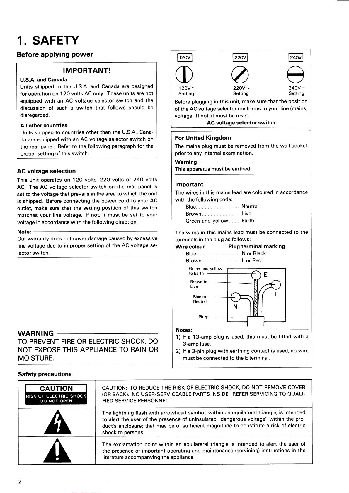
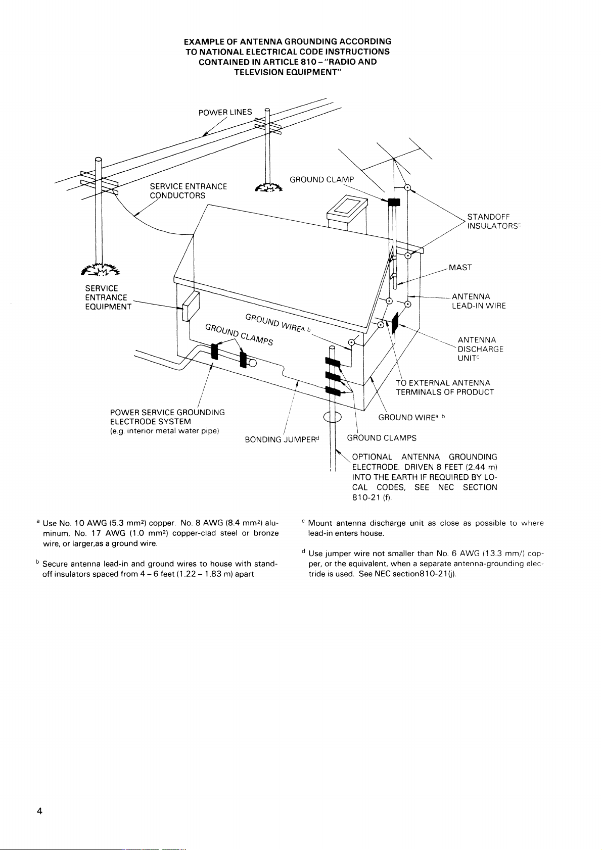
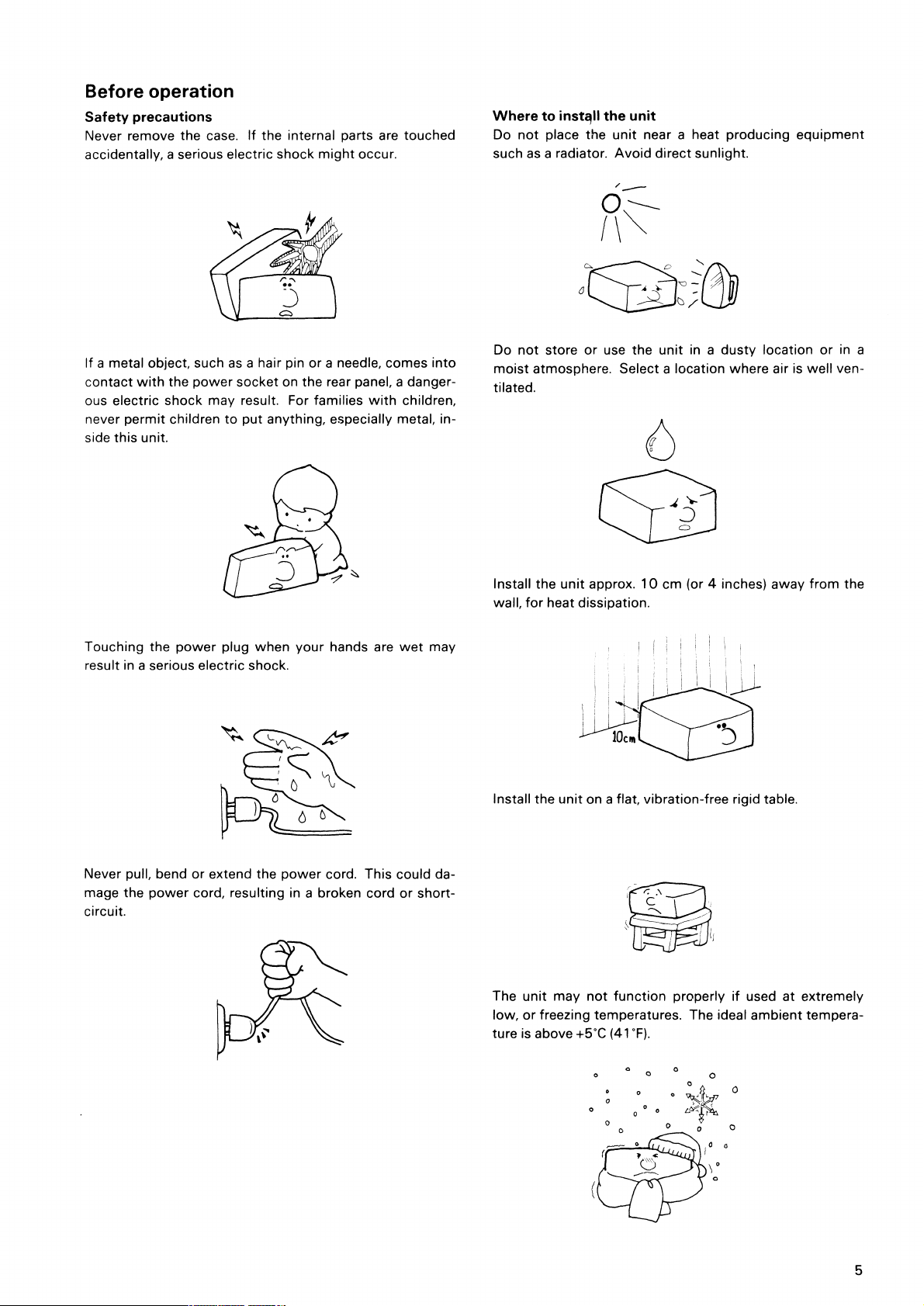
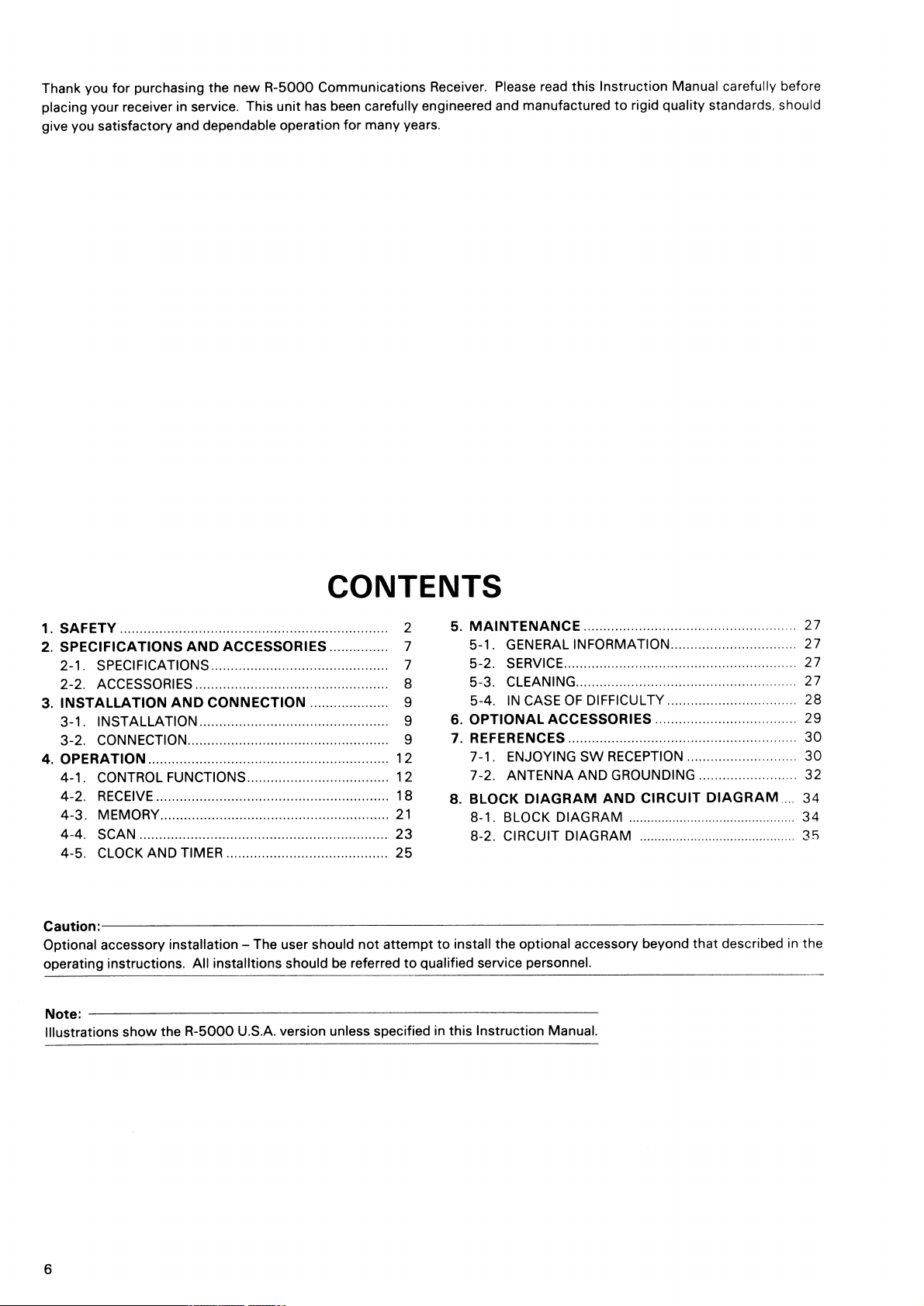
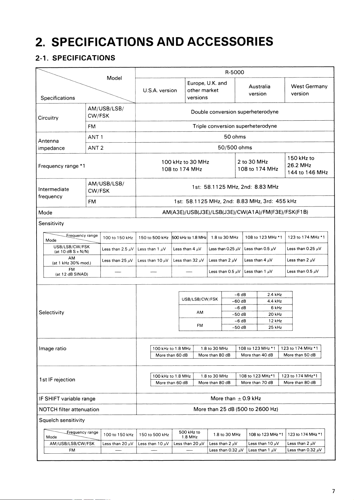
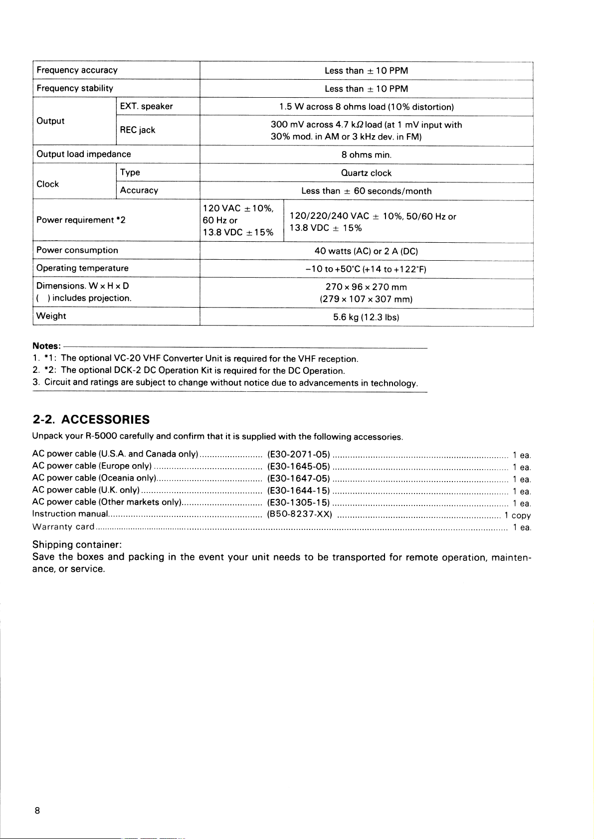
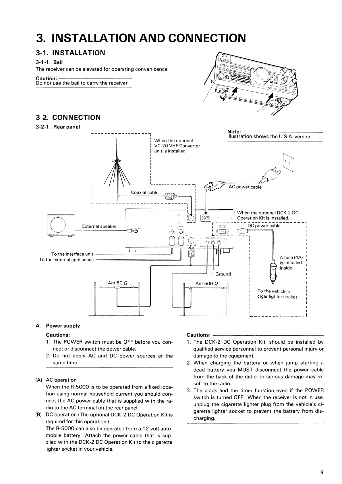
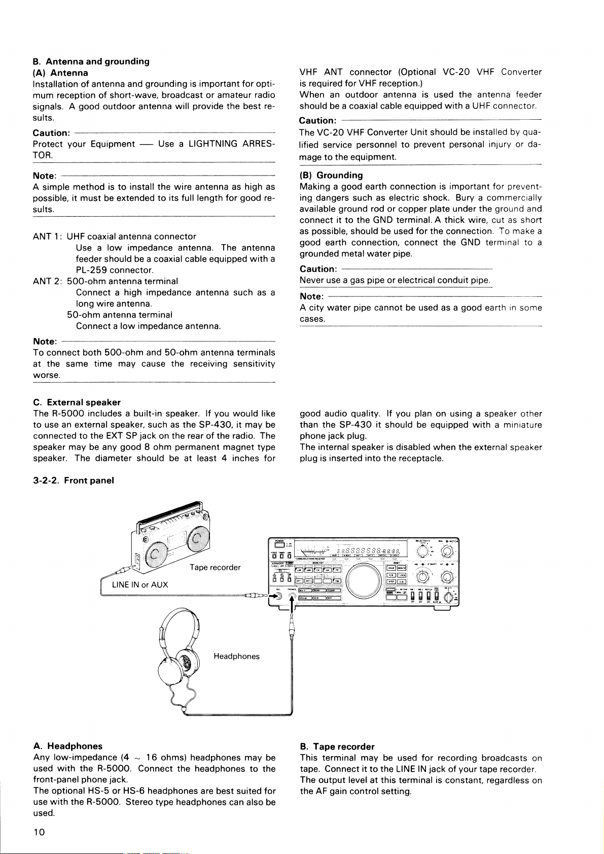
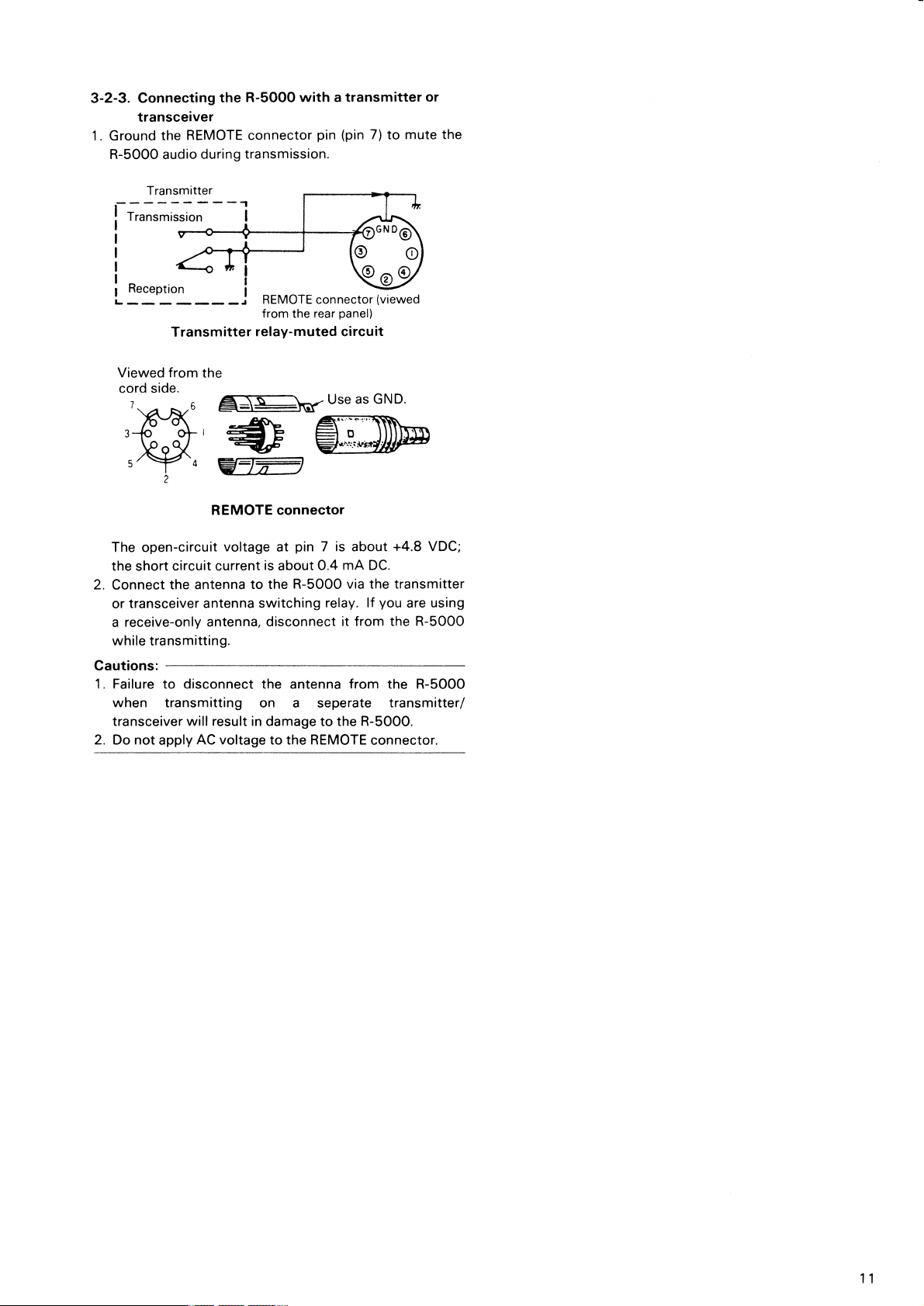


 Loading...