

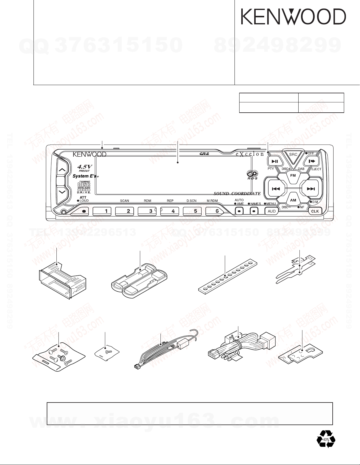
CD RECEIVER
KDC-X915/X815
Q
Q
3
7
6
3
1
5
1
5
0
PS9016R/PS9080R
SERVICE MANUAL
●KDC-X915
TEL 13942296513 QQ 376315150 892498299
∗Escutcheon
(B07-2183-02)
KDC-X915
∗Front glass
(B10-3107-01)
8
4
2
9
© 2000-1 PRINTED IN JAPAN
B51-7571-00(S) 3448
Extension cord
CD mechanism(22P) W05-0618-00
DISP
9
∗Panel assy
(A64-1867-02)
8
2
9
9
Parts No.
TEL 13942296513 QQ 376315150 892498299
TEL
Mounting hardware assy
(J21-9491-03)
Screw set
(N99-1652-05)
13942296513
Screw set
(N99-1683-05)
Plastic cabinet assy
(A02-1489-03)
(E30-4779-05):KDC-X815
(E30-4781-05):KDC-PS9016R
(E30-4782-05):KDC-X915
Q
Q
1
5
1
3
6
7
3
Stay
(J54-0606-04)
(E30-4788-05):KDC-PS9080R
5
0
∗ : Refer to the Parts List
9
4
2
9
8
Lever x2
(D10-4301-14)
(D10-4302-14)
Bracket
(J19-4875-04)
(J19-4876-04)
8
2
9
9
w
w
The MECHANISM OPERATION DESCRIPTION is the same as model KDC-S3007 and KDC-5050RG.
Please refer to the service manual for model KDC-S3007(B51-7029-00) or KDC-5050RG(B51-7099-00).
w
.
xia
o
y
u
1
6
3
.
c
o
m
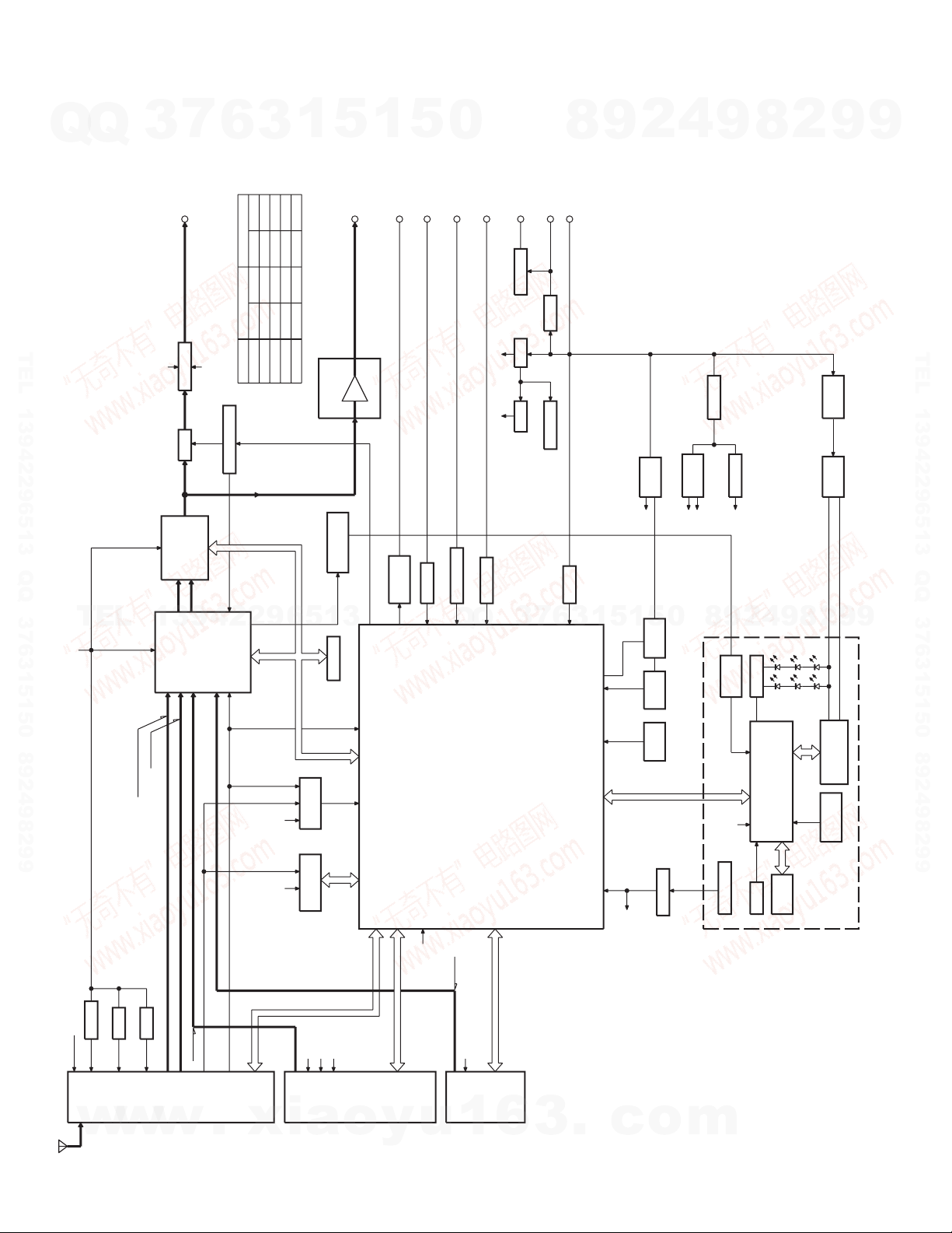
KDC-X915/X815/PS9016R/PS9080R
COM+B
FM+B
AM+B
E2PROM
DIMMER
2WAY MUTE
ACC DET.
SRMPHOT
BU DET.
SRM
DRIVER
A8V
SERVO
DC/DC
SW14V
SW5V
BU5V
P CON
ANT-CON
MUTE DRIVER
4.5V PRE
MUTE
E's
POWER IC
IC4
IC14
u-com
IC1
CD
CH
IC10
IC7-9
IC5
IC2
F/E
MECHADET.
E-VOL
PREOUT
SP-OUT
DIMMER
TEL-MUTE
ACC
ANT-CONT
P-CON
BACK UP
DECORDER
RDS
IC11
IC16
EX.AMP CONTROL
AVR
DC/DC
BOX
PANEL u-com
RESET SW
RESET IC
VFD
REMO
G/R SW
SPEANA
IC15
ANT. IN
AMP
IC12
NOISE
PREOUT OUTPUT VOLTAGE
SPEANA
AGC OPAMP
CONTROL
EX.AMP
NAVI-MUTE
PANEL 5V
4.5VPRE
IC3
IC6
DC/DC
REG
MATRIX
KEY
LOCK SW
PANEL
BFP
FL TYPE
PLL CLK
CH
MO SW
SERVO+B
LO/EJ
STOP
MUTE
DATA S
CLK
SW2
CS
SQR
DATA M
SW3
SW1
A8V
BU5V
RST
REQ C
CLK
CH-CON
DATA H
REQ H
CD
AM
FM
MUTE
MC REQ
PANEL RST
SC REQ
MC CLK
SC DATA
RESET
SRM SW1
SRM DET
SRM SW2
RDCK
RDDA
QUAL
SDA
SCL
A8V
+B
-B
+B
-B
PLL DATA
PLL CE
S-METER
SW5V
SW5V
DATA C
BACK UP
PANEL 5V
FAC
FL+B
750mV
4500mV
CHANGER
AM
4.5V PRE
2250mVFM
160mV
1200mV
1200mV
213mV (E TYPE)
400mV (K TYPE)
RDS OUT
FM+B
NOISE
4500mVCD
K TYPEMODE
4500mV
4500mV
1069mV
1715mV
E TYPE
3600mV
600mV
1800mV
3600mV
K TYPE E TYPE
3600mV
1372mV
855mV
3600mV
1.8V PRE
SRM SUBSRM SUB+
DRIVER
MUTE
BU5V
DC/DC IS FL ONLY
RST
BLOCK DIAGRAM
Q
Q
3
6
7
TEL 13942296513 QQ 376315150 892498299
3
1
5
1
5
0
8
9
2
4
9
8
2
9
9
TEL 13942296513 QQ 376315150 892498299
TEL
13942296513
Q
Q
3
7
3
6
1
5
1
5
0
8
9
2
4
9
8
2
9
9
2
w
w
w
.
xia
o
y
u
1
6
3
.
c
o
m
MICROCOMPUTER'S DESCRIPTION
7
Q
Q
System µ-com: UPD784217GC
●Terminal description
TEL 13942296513 QQ 376315150 892498299
TEL
w
3
No. Pin name Function I/O Description Processing Operation
1 P120/RTP0 CHCON1 O Changer 1 control Active: Hi
2 P121/RTP1 CH_MUTE I Changer muting input MUTE Requested : Hi
3 P122/RTP2 REQH O Handshake request to changers Active: Lo
4 P123/RTP3 ILL_ON O Illumination output Active: Hi
5 P124/RTP4 NC O Open
6 P125/RTP5 CD_SW2 I 12cm DISC detection ON: Lo
7 P126/RTP6 CD_SW1 I Loading detection ON: Lo
8 P127/RTP7 NC O Open
9 Vdd Vdd - Positive power supply
10 X2 X2 - Main clock connection
11 X1 X1 - Main clock connection
12 Vss Vss - GND
13 XT2 XT2 - Sub clock connection
14 XT1 XT1 - Sub clock connection
15 RESET RESET I Reset input Active: Lo
16 P00/INTP0 CH_RST O Changer reset output Active: Lo
17 P01/INTP1 R_CLK I RDS clock input
18 P02/INTP2/NMI REQC I Handshake request from changer Active: Lo
19 P03/INTP3 NC I/O
20 P04/INTP4 NC I/O
21 P05/INTP5 NC I/O
22 P06/INTP6 SC_REQ I Handshake request from panel µ-com
23 AVdd AVdd - A/D analog power supply
24 AVref0 AVref - A/D reference voltage input
25 P10/AN10 PHONE I PHONE detection terminal 1V or less: PHONE
26 P11/ANI1 SRM_SW1 I SRM position detection Open: Hi
27 P12/ANI2 NOISE I FM noise detection Analog input
28 P13/ANI3 SMETER I FM signal meter detection Analog input
29 P14/ANI4 IF_MODE I K2I IF selector Wide: Hi/Narrow: Lo
30 P15/ANI5 NC I GND
31 P16/ANI6 M_MUTE_R I Mute request from mechanism Mute requested: Lo
32 P17/ANI7 M_MUTE_L I Mute request from mechanism Mute requested: Lo
33 AVss AVss - A/D GND
34 P130/ANO0 EXT_AMP O EXT_AMP control
35 P131/ANO1 M_RST O Reset output to mechanism Reset: Lo
36 AVref1 - D/A reference voltage input
37 P70/RxD2/SI2 DATAC I Data line from changer
38 P71/TxD2/SO2 DATAH O Data line to changer
39 P72/ASCK2/SCK2 CH_CLK I/O Clock line from/to changer
40 P20/RxD1/SI1
41 P21/TxD1/SO1
42 P22/ASCK1/SCK1 L_CLK/MC_CLK I/O Clock line to LCD driver
43 P23/PCL M_STOP O Stop request to mechanism Stop requested: Lo
44 P24/BUZ BEEP O Beep output Active: Hi
45 P25/SI0 PLL_CE O CE output to PLL
46 P26/SO0 PLL_DATA I/O Data in/out with PLL
47 P27/SCK0 PLL_CLK O Clock output to PLL
48 P80/A0 CD_SW3 I Switch detection ON : Hi
49 P81/A1 LO/EJ O Loading/Eject control Loading: Lo/Eject: Hi
50 P82/A2 MOSW O Motor output Loading: Hi/Eject: Lo
51 P83/A3 MECH_ DET I Mechanism detection ON: Hi/OFF: Lo
52 P84/A4 PAN5V O Panel detection OFF: Hi
53 P85/A5 L_CE/P_RST O CE to LCD driver/Panel µ-com reset
54 P86/A6 L_INH/MC_REQ O Reset to LCD driver
13942296513
w
w
6
.
xia
1
3
L_DATAL/SC_DATA
L_DATAS/MC_DATA
5
o
1
5
0
Q
Q
I Data line from LCD driver
I/O Data line to LCD driver
y
u
1
6
3
7
3
6
8
3
.
9
1
1
5
c
2
5
o
4
0
8
8
9
4
2
9
2.5V or more: NAVI MUTE
m
2
9
8
9
2
9
9
TEL 13942296513 QQ 376315150 892498299
9
3
KDC-X915/X815/PS9016R/PS9080RKDC-X915/X815/PS9016R/PS9080R
MICROCOMPUTER'S DESCRIPTION
7
Q
Q
No. Pin name Function I/O Description Processing Operation
55 P87/A7 DIM_CON O DIM control
56 P40/AD0 QUAL I RDS receiving condition Good: Hi
57 P41/AD1 R_DATA I RDS data input
58 P42/AD2 SRM_SUB- O SRM sub motor output
59 P43/AD3 SRM_SUB+ O SRM sub motor output
60 P44/AD4 SRM_DET I SRM mechanism detection ON: Lo/OFF: Hi
61 P45/AD5 SRM_SW2 I SRM eject detection : Eject
62 P46/AD6 FM_SD I FM SD input Station detected: Hi
63 P47/AD7 NC O Open
64 P50/A8 AFC O Noise detection time constant switching During reception: Hi
TEL 13942296513 QQ 376315150 892498299
65 P51/A9 O
66 P52/A10 WIDE O K2I Wide output Active: Hi
67 P53/A11 NARROW I/O K2I Narrow output Active: Hi
68 P54/A12 AM+B O AM power supply Active: Hi
69 P55/A13 FM+B O FM power supply Active: Hi
70 P56/A14 NC O Open
71 P57/A15 NC O Open
72 Vss - GND
73 P60/A16 TYPE0 I Destination type switch
74 P61/A17 TYPE1 I Destination type switch
75 P62/A18 TYPE2 I Destination type switch
76 P63/A19 ST_TYPE0 I IC2 Var. 3 destination type 0 Initial value: Lo
77 P64/RD ST_TYPE1 I IC2 Var. 3 destination type 1 Initial value: Lo
78 P65/WR NC O Open
79 P66/WAIT PRE MUTE R O Open Active: Lo
TEL
80 P67/ASTB PRE MUTE L O Open Active: Lo
81 Vdd - Positive power supply
82 P100/TI5/TO5 NC O Open
83 P101/TI6/TO6 SVR O Power IC reset Power ON: Lo
84 P102/TI7/TO7 NC O Open
85 P103/TI8/TO8 P_MUTE O Power IC muting Active: Lo
86 P30/TO0 ANT_CON O Antenna control Active: Hi
87 P31/TO1 IC2_SCK O IC2, IC5, EEPROM clock line
88 P32/TO2 DIMMER I Dimmer detection Active: Lo
89 P33/TI1 P_CON O Power control Active: Hi
90 P34/TI2 ACC_DET I ACC detection ACC OFF: Hi
91 P35/TI00 REMO I Remote control input
92 P36/TI01 P_ON O µ-com peripheral power supply Active: Hi
93 P37 BU_DET I Momentary power down detection Momentary power down: Hi
94 TEST - Test GND
95 P90 IC2_SDA I/O IC2, IC5, EEPROM data line
96 P91 MUTE O Muting output Active: Hi
97 P92 SW5 O 5V power supply Active: Lo
98 P93 MS_CL O CD mechanism clock line
99 P94 MS_DA I/O CD mechanism data line
100 P95 O NC
3
13942296513
6
3
1
5
1
5
0
Q
Q
3
7
8
6
3
9
1
5
2
1
5
4
0
8
9
Not detected: Lo
During search: Lo
4
2
9
8
2
8
9
9
9
2
9
TEL 13942296513 QQ 376315150 892498299
9
w
w
w
.
xia
o
y
u
1
6
3
.
c
o
m
4
TEST MODE
7
Q
1.Entering the test mode
2.Releasing the test mode
TEL 13942296513 QQ 376315150 892498299
3.Voltage adjustment on the FM S-meter
4.Writing SD voltage for the AM
5.Forced switching of K2I Auto/Manual
6.Forced narrow/wide switchng of K2I
7.CD receiver test mode specification
Q
Reset the unit by pressing the FM key and the Preset 6 key
at the same time.
When the test mode is entered, all indicators light up.
Reset the unit by pressing the Preset 6 key.
Note: The unit cannot be reset by simply turning ACC off,
(1) Enter the test mode.
(2) While pressing the Preset 1 key, keep on pressing the
Preset 6 key.
(3) When the adjustment is made, "ADJ OK" is displayed.
When adjustment cannot be made, "ADJ NG" is
displayed.
(1) Enter the test mode.
(2) While pressing the Preset 1 key, keep on pressing the
Preset 6 key, which results in writing SD.
TEL
In tuner-mode, keeping on pressing TI key, and the Auto
and Manual modes can be swieched. The initial condition
is manual modes, which is indicated by flashing DUAL dots.
In tuner-mode, when Preset 6 is pressed, forced narrow/
wide mode switching is made. The initial condition is in wide
mode and the NEWS dot flashes.
By pressing the track-up key, the unit jumps to the following
tracks:
No. 9 ➔ No. 15 ➔ No. 10 ➔ No. 11 ➔ No. 12 ➔ No. 13 ➔
No. 14 ➔ No. 9 (Goes back to the first position.)
When the track-down key is pressed, the unit jumps to the
previous track.
3
turning power off, or turning power off for a brief
moment.
13942296513
6
3
1
5
1
5
0
Q
Q
9
9.Tape test mode
10.Audio-related items
11.Backup current measurement
12.Registering security code after changing
8
In the initial step, the blank skip is turned off.
• The volume is -10dB (on display, it is 30).
• The loudness is off and CRSC is off regardless of
functions.
• Buss/treble and balance/fader are to be adjusted by the
up/down key to full-boost/fullcut and fullfront/fullrear
respectively.
• The high-pass filter is adjusted by the up-key to
throughput/100Hz/200Hz and, by the down-key, to
200Hz/100Hz/throughput.
• Other adjustments are the same as before.
When reset in ACC-off condition (backup is on), the mute
terminal goes off after 2 seconds instead of 15 seconds,
when the ACC is tuned off in the test mode. (In this case,
the panel/CD/C/MD mechanisms are not activated.)
E2PROM at the services (Only for type
M. However, RDS models are excluded)
(1) Put the unit into the test mode (Refer to 1. Above for
7
3
(2) Press SRC key to put the unit into the tuner mode.
(3) Press Audio key for one second and put the unit into
(4) Press FM/AM key and then select "SECURITY."
(5) Press track up/down key for full 2 seconds.
(6) Press Preset 1, Preset 2, Preset 3, and Preset 4 and
(7) Press DISP key for 3 seconds and confirm that
(8) Release the test mode. (Refer to "2. Releasing the test
1
3
6
how to enter the test mode.)
the menu mode.
then input codes.
Example: Inputting "3510."
"APPROVED" is displayed.
mode" above.)
4
2
5
1
5
• Preset 1 key 4 times.
• Preset 2 key 6 times.
• Preset 3 key 2 times.
• Preset 4 key once.
0
9
8
9
2
8
4
2
9
8
9
9
2
9
TEL 13942296513 QQ 376315150 892498299
9
8.MD test mode specification
After loading MD, the unit plays No. 7. Then, the unit jumps
as follows each time it track-ups.
No. 2 ➔ No. 13 ➔ No. 23 ➔ No. 30 ➔ No. 34 ➔
No. 7 (Goes back to the first position.)
When the track-down key is pressed, the unit jumps to the
previous track.
w
w
w
5
.
xia
o
y
u
1
6
3
.
c
o
m

KDC-X915/X815/PS9016R/PS9080RKDC-X915/X815/PS9016R/PS9080R
TEST MODE
7
Q
Q
13.Simplified method for clearing the
security code (Only for type K)
(1) When code is requested, continue pressing VOL UP
(2) Input "KCAR," using the remote controller (the same
TEL 13942296513 QQ 376315150 892498299
(3) Then, the security is released and the unit goes into
14.Writing MASK KEY on line (E2PROM in
initial codition)
(1) While pressing the FM key and Preset 6 key, press
(2) Press AUDIO key for full one second to put the unit
(3) Select the "MASK KEY," using the
TEL
(4)
(5) Point the MASK KEY to the light receptor and press it
(6) When "TRANSMIT 2" is displayed, press MASK KEY
(7) When "APPROVED" is displayed, writing is completed.
15.
Releasing MASK KEY requests (When
reset or backup is off when MASK KEY is
approved)
(1) When power is turned on, "TRANSMIT 1" is displayed
(2)
(3) When "TRANSMIT 2" is displayed, press the MASK
(4) When "APPROVED" is displayed, MASK KEY is
w
3
key for three seconds while pressing the DISP key.
(.... disappear.)
as the 98 Model)
• Press Tenkey 5 twice and then press track-up key.
(Inputting "K")
• Press Tenkey 2 three times and then press track-up
key. (Inputting "C")
• Press Tenkey 2 once and then press track-up key.
(Inputting "A")
• Press Tenkey 7 twice and then press track-up key.
(Inputting "R")
the Tuner Mode.
reset key to enter the test mode.
into the menu mode.
13942296513
Press on the track up/down key to display "TRANSMIT 1."
for 0.5 second or longer.
for 0.5 second or longer. When this is conducted, the
counter codes for the first time and the second time
will not be compared.
Time the demonstration mode is set and the test mode
is released.
Note: After an elapse of 30-minuite period, during
which no code is written, an error is effected
and the device will power off.
and the unit goes into MASK KEY request mode.
Point the MASK KEY to the light receptor and press it for
more than 3 seconds (until the level display indicates full)
KEY again for more than three seconds. At this point,
when "TRANSMIT 1" is displayed, repeat the process
in (2) above for the second time.
approved and the unit turns power on.
w
w
6
.
xia
3
1
5
FM key or AM
o
1
y
5
key.
u
0
16.
Initializing MASK KEY (returning to the
default condition from MASK KEY
approved state)
(1) While pressing the FM key and Preset 6 key at the
same time, press RESET to enter the test mode.
(2) "TRANSMIT 1" is displayed and the unit goes into
MASK KEY request mode. The display at this point will
be "**" instead of "[ ]".
(3) Use MASK KEY release remote controller for more than
three seconds.
(4) When "TRANSMIT 2" is displayed, press the MASK
KEY for more than three seconds for the second time.
(5)
When "APPROVED" is displayed, the MASK KEY is
released and the demonstration mode is set. Then, the test
mode is released, returning the unit into default condition.
17.Clearing from the MASK KEY
(1) While pressing FM key and Preset 6 key at the same
time, press RESET to enter the test mode.
(2) Press the AUDIO key for full one second to put the unit
into the menu mode.
(3) Select MASK KEY, using track up/down key.
(4) Press on the FM key or AM key for full two seconds
and the unit will display "TRANSMIT 1."
(5) Point the MASK KEY release controller to the light
7
3
Q
Q
1
receptor and press it for 3 seconds or longer. (Until the
level display indicates full.)
(6) When "TRANSMIT 2" is displayed, press MASK KEY
for 3 seconds or longer for the second time. If
"TRANSMIT 1" is displayed, start again from (5) above.
(7)
When "APROVED" is displayed, E2PROM is cleared.
The unit goes back to the condition described in Line
14: Writing MASK KEY on line (E2PROM in initial
condition)
18.Other
• Automatic panel closing does not occur in case a TAPE,
CD, or MD is inserted.
• Panel is opened/closed when ATT key is turned On/Off.
(A remote controller is used when turning ATT on.)
• The DNPP/SBF key of the remote controller (RC-510) is
used for tuning the menu mode On/Off.
• The OPEN/CLOSE key of the remote controller (RC-510)
is used for tuning the audio mode On/Off.
• The feed on the menu will be feeds only for necessary
features.
• "CODE OFF" and other displays will not be issued when
the power is turned on.
•
The dimmer of the FL model and contrast on the LCD model
can be adjusted only for 0/5/10 by the UP/DOWN key.
6
3
6
8
3
.
9
1
1
5
c
2
5
o
4
0
m
9
8
9
8
2
4
2
9
8
9
2
9
9
TEL 13942296513 QQ 376315150 892498299
9
6
KDC-X915/X815/PS9016R/PS9080R
ADJUSTMENT
KDC-PS9016R/PS9080R
7
Q
Q
Set the controls and switches as follows.
BALANCE: center position BASS: center position LOUD: OFF DOLBY NR: OFF
FADER: center position TREBLE: center position
TEL 13942296513 QQ 376315150 892498299
3
No ITEM INPUT SETTINGS OUTPUT TUNER ALIGNMENT ALIGN FOR FIG.
FM SECTION
1 SEPARATION 98.1MHz Connect an TEST MODE: ON VR1 Adjust it so that
(NARROW) 1kHz, ±40kHz dev AC voltmeter (Forced Narrow) the crosstalk
6
60dBµ (ANT input) FM98.1MHz
1
5
1
3
Pilot: ±6.0kHz dev to SP OUT from L to R and R to L
Selector: L or R become minimum.
5
0
SETTINGS (RECEIVER) POINTS
SETTINGS
J1
8
9
2
4
9
8
2
9
9
TEL 13942296513 QQ 376315150 892498299
TEL
13942296513
Q
Q
(X25-)
FRONT
3
SEPARATION
VR1
3
6
7
1
5
1
5
0
8
9
2
4
9
8
2
9
9
w
w
w
.
xia
o
y
u
1
6
3
.
c
o
m
7
A B C D E
KDC-X915/X815/PS9016R/PS9080R
PC BOARD (Component/Foil Side View)
1
7
C5
SRC
D8
FL+B
FAC
VDD
R33
D GND
CP3
X1
CP2
CP1
SC D
R22
R3
R4
14
R5
R20
C8
6
R35
13
R11
Q5
Q1
S15
3
EJECT
S19
FM
S18
S20
P RESET
MC CLK
L1
26
25
1
100
D1 D2
13942296513
R34
Q2
EB
R1
LOCK
KR4
R17
KR5
D5
R21
BE
Q3
C6
KR1
R19
R18
IC3
21
EB
R31
EB
EB
Q8
Q
Q
SWITCH UNIT
X13-9710-10 (J74-0983-12)
D7
14
2
TEL 13942296513 QQ 376315150 892498299
3
S14
2
ED1
41 43
SRC
TEL
4
5
6
6
R14
Q6
EB
R13
R15
CN1
115
L2
C1
R24
D4
R2
34
S6
S17
S4
MC REQ
SC REQ
KS1
KS3
CP4
IC1
KS4
18
10
C2
C3
R10
OPEN
RST
R9
C4
R30
S16
SG
R8
ANA
R12
S22
R16
FL G
KR2
KR3
R23
L3
L4
50
5175
76
R25
1
IC2
9
D3
KS2
S23
OPEN
3
Q7
BE
S9S12S10
S3
S7
S2 S1
S13S11
R7
R6
C7
S21
RST
S8
S5
CLK
MENU
DISPAUTO
65
4321AT T
1
5
1
SWITCH UNIT
(X13-971X-XX)
.ON.feR
CIQ
1A3
2B5
3A6
1A6
2A4
3A5
5A6
6A2
7B2
8A6
5
sserddA
0
Q
Q
SWITCH UNIT
(X13-971X-XX)
.ON.feR
CIQ
1D3
2D5
3E6
1E6
2E4
3E5
5E6
6D2
7D2
8E6
6
7
3
8
sserddA
3
9
1
4
2
SWITCH UNIT
Q7
EB
CLK
R16
S8
FL G
MENU AUTODISP
S5
S9
L3
L4
S3
S7
7551
56
0
5
1
5
34
S13S2S1
1
S12
9
R7
R6
D3
12
S11
C7
KS2
S10
ATT
S23
OPEN
RST
S21
R14
KR2
R23
R25
KR3
50
76
2
L1
R33
R1
FL+B
VDD
CP2
CP1
BE
8
SC D
R3
R4
R5
R21
C6
R19
BE
SRC
FAC
D GND
R22
R11
Q1
C5
CP3
X1
SRC
2
R20
C8
R35
Q5
9
D7
14
S14
D8
2
ED1
4143
9
14
6
13
S15
8
9
X13-9710-10 (J74-0983-12)
Q6
EJECT
R15
MC CLK
L2
C1
2
R24
R17
D4
R2
15
CN1
1
P RESET
26
100
D1D2
4
B
E
LOCK
KR4
KR5
D5
E
B
KR1
IC3
1
R31
BE
Q8
S19
FM
S18
S20
25
1
R34
9
Q2
Q3
R18
423
R13
ANA
MC REQ
KS3
R30
R12
8
KS4
S22
R8
IC2
S16
SG
BE
S6
S4
KS1
CP4
9
C2
C3
R10
OPEN
RST
R9
S17
SC REQ
IC1
18
10
C4
9
TEL 13942296513 QQ 376315150 892498299
9
w
w
w
7
.
xia
o
y
u
1
6
3
.
c
o
m
8

R161
R106
R173
R140
R131
R63
R61
R65
R68
C37
R46
R144
R41
R43
R44
R42
R45
BE
C166
R31
R33
C23
R143
R197
C34
R82
R102
R248
R84
C35
L11
C36
R93
W18
R107
R103
R104
R100
W20
R105
W21
C38
C157
R38
W26
R17
R246
R48
R47
R30
BE
BE
R22
B
R25
R24
E
E
B
EB
C160
R18
R23
L2
R21
R2
C7
R8
E
R9
R7
EB
C4
R1
B
R34
R37
W27
R155
EBEB
B
R3
E
C105
R210
R209
R69
R74
R89
12
34
R78
R77
C13
BE
R64
R243
R73
R62
R60
R244
R205
R206
R207
R208
C106
R203
R177
R178
W15/C87
W14/C88
R170
W13/C83
R169
W12/C84
R50
C30
R51
R164
R168
R167
R157
R158
R156
R162
R175
R163
R176
R166
EB
C126
C124
C123
C127
C110
C128
C125
C26
R86
C25
R16
R56
R57
C31
R35
EB
C2
C162
R135
R132
R130
E
C50
B
R139
814
EB
R126
R122
R97
610
C121
C120
BE
C118
R11
C142
BE
15
C116
C115
C122
C153
C151
R40
W6
R125
7
1
C32
R72
W5
EB
BE
R123
C39
W3
W2
W4
C78
C77
W1
C74
C75
C76
C73
EB
C68
C79
C80
C62
C63
C59
L10
R39
C54
R229
BE
C133
R221
E
C141
R230
R228
C140
B
C138
R224
R222
C136
R225
C134
C148
R223
C137
C159
R193
R195
R194
C56
R236
R234
C55
R147
BE
BE
R187
C28
EEB
TH1
B
EB
R182
R181
R189
R183
R184
R186
R188
L5
C144
R145
R232
C145
C146
W16
R215
C149
R237
W17/C150
Q10
D16
D60
D21
Q55
Q14
Q19
Q18
Q20
Q2
Q52
IC15
Q5
Q12
Q3
Q6
Q22
D43
D32
Q26
Q32
D59
D56
Q41
D53
D58
D57
D55
D54
IC10
Q43
IC13
Q44
Q30
D47
Q45
Q33
Q42
D29
D28
Q49
Q51
D41
D13
Q25
D37
D39
Q24
Q38
D35
D34
D36
D38
D42
D40
D33
Q31
CN3
CN5
D5
D18
Q9
Q8
D8
IC1
CN1
CN8
D11
Q21
D19
IC6
D50
Q56
Q54
D6
Q16
Q15
Q17
Q13
D7
Q4
IC3
Q53
D3
Q1
D12
Q11
IC9
Q39Q40
Q35
Q29
Q28
D2
Q36
IC7
Q34
IC8
Q37
Q23
D20
J1
D1
D31
CN7
D51
D22
CN6
D4
IC11
Q7
IC5
IC14
D48
IC16
D27
D24
D23
IC2
IC12
CN4
Q48
Q50
IC4
CN2
WH1
A1
C82
R165
R201
C104
R204
R202
E
75
51
12.0M
R27
R32
C20 C17
RESET
R79
C19
C163
C164
PH1
R13
C161
8
BE
C16
R101
R83
R12
R14
BE
C21
R29
R28
222
R118
32.768k
21
R137
R242
R96
R138
R80
X2
R95
X1
R116
1
R99
CP6
R92
R117
W19/
R108
CP5
CP4
25
26
50
R15
E
R245
1
14
C18
61
BE
EB
C24
85
B
B
E
E
B
E
C22
BE
W28/C12
R19
C14
C5
I
G
O
B
E
B
E
R6
R5
BE
C3
C8
C6
R59
TEST
R20
C33
R241
C15
R76
REAR
(3PRE)
L1
EB
R4
R70
R67
C51
100
1
R71
76
R66
1
R53
4
8
5
EB
B
EB
B
8
R52
N-F/REAR
R58
BE
(2P)
EB
B
FRONT
E
W10
W8
W9
1
4
5
1
8
4
EBEB
R154
W11
5
BE
E
C91 C92 C90 C89
R211
R171
R212
C108C107
1
R179
R172
R180
R26
8
9
9
R54
1
16
C1
SMTR
FMSD
R127
R120
L3
R90
R112
113
R119
R136
R134
122
R198 R247
CP3
CP9
CP2
R199
R110
R133
R111
R174
R196
R128
1
R200
C45
4
C10
4.332M
9
X3
16
R113
8
C165
1
IFMODE
C117
C44
C119
1
5
3
42
L9
C147
C131
R218
R220
R149
C69
C70
C72
C52
R121
C81
58
R142
1
CP7
R141
4
R124
R115
C43
C103
15
R129
8
C46
C42
5
C53
14
C71
C61
R151
C85
C86
R153
R160
C67
R159
B
R191
1
C64
28
C60
R152
R190
C95
C58
C49
C48
C65
C66
NOISE
33
34
44
1
R114
R227
C139
C135
1
1
R231
R226
R94
C130
8
R216
R219
C132
5
R148
23
22
C112
12
C111
11
C113
C96 C97
231
C98
R185
E
C57
R233
BE
L6
R235
B
R192
L7
C29
1
C101
C27
214
C100
C99
C102
15
21
L4
R217
24
VR1
1
2
L8
1
X25-8462-70/8470-10 (J74-1000-12)
F G H I J K L NM
PC BOARD (Component Side View)
ELECTRIC UNIT
X25-8462-70/8470-10 (J74-1000-12)
7
CN3
R45
R44
D16
C21
R29
C23
R28
R33
R79
RESET
C35
C36
R82
W20
C38
W21
14 8
CP2
D22
R97
R122
C45
C44
C142
Q43
C122
42
C16
C19
R95
12.0M
CP9
EB
Q32
R128
R127
1
4
FMSD
Q44
SMTR
CN7
5
R46
C17
C20
R31
R27
R32
C37
X1
C34
R68
R65
R61
R63
R120
IC10
3
R126
IFMODE
EB
D31
13
Q15
E
Q18
34
R69
Q30
Q45
D23
R114
R94
IC15
R230
R48
R47
IC6
R24
R25
EB
B
B
E
EB
C22
R89
R241
12
R78
R74
1
R64
R60
76100
75
1
CP7
C32
7
R115
R124
R125
9
EB
EB
8
5
C39
IC16
C66
EB
Q42
C141
R227
C139
EB
R231
R226
L4
14
85
Q20
D21
C33
R62
1
4
R129
C46
R121
NOISE
1
4
C140
R220
C144
24
R41
PH1
C164
C161
D5
R12
R101
R83
C166
R144
R137
32.768k
R242
R96
R118
R92
CP6
R99
W18
R117
CP5
R107
R108
CP4
R139
D57
D58
D55
D54
D53
C165
R11
8
1
15
3
C163
D18
R138
X2
R84
L11
R102
26
R100
R93
R105
50
R106
D51
R134
R133
R136
R119
R174
R196
R200
L3
R42
R43
BE
Q9
BE
Q8
D8
R80
25
R104
R103
IC1
51
R247
CP3
R198
R110
R199
R111
1
C119C117
Q7
w
Q
Q
Q10
R13
BE
R14
TEL 13942296513 QQ 376315150 892498299
R143
D60
R131
D59
R135
D56
R130
C50
C120
C121
R197
R132
T
E
EB
Q41
R112
R90
C162
X3
4.332M
C10
D4
w
169
22
2
610
EB
13
1
R140
CN6
R113
CN5
21 1
R248
R116
W19/
R173
212
L
C118
IC11
IC13
C116
C115
w
C157
6
CN8
Q55
6118
BE
D50
R246
Q56
C18
BE
Q14
EB
R23
BE
L2
B
Q19
E
B
Q16
C24
R22
Q11
R20
TEST
R59
C51
R71
R70
R67
Q31
R142
R141
IC14
58
4
C42
14
R123
C53C43
C52
D24
C65
C48
C133
IC12
C138
R224
R217
.
C160
Q13
D7
C14
EB
C13
Q12
L1
EB
1
C106
R53
4
R206
EBEB
EB
D48
2
W2
W4
W3
C76
C75
C70
C71
C72
33
34
44
1
C130
R225
C134
C136
85
C137
R223
R219
C132
C131
VR1
C145
R21
(3PRE)
R210
IC9
R208
R207
R203
Q39Q40
R204
C103
D47
W5
IC5
W1
C74
C69
R216
R232
C146
R19
R18
REAR
R222
Q17
R77
R73
R66
R72
C135
R30
E
C15
R76
R243
R229
R228
R221
R218
R244
Q54
W28/C12
Q3
Q5
R4
Q6
R209
R155
Q35
R202
2
C77
C73
C61
IC2
C49
C148
C159
R145
x
EB
D6
R3
EB
EB
C105
8
5
R205
C81
W6
C78
C58
R245
C54
3
B
G
O
I
R8
IC3
R9
EB
Q52
C8
R17
Q29
BE
R58
C30
BE
R52
R50
BE
R51
Q28
(2P)N-F/REAR
W12/C84
R169
R170
W13/C83
1
IC7
5
4
R167
R157
R168
W8
W9
R162
R156
EBEBEBEB
Q34
C104
R201
R153
9
1
C79
C80
C62
2815
C59
C63
R149
22 12
R148
C111
1123
C56
R147
C55
C57
R233
Q49
Q48
Q51
BE
C147
C149
L5
R237
R215
W16
W17/C150
E
C6
8
R158
R154
BE
BE
L6
E
C7
R6
1
R164
Q36
6
C113
i
D19
Q33
C112
BEBE
R236
R7
W14/C88
4
C64
1
R5
Q53
B
C5
FRONT
R178
R176
W10
C82
R161
R160
R159
C86
C67
C85
R151
L10
C60
D29
R194
R195
R234
R235
Q1Q4
BE
BE
Q2
R1
R2
D2
R177
8
IC8
5
R175
W11
Q37
R166
R165
C68
5
R191
R190
R152
D28
231
R193
Q50
L7
C153
C151
a
5
D3
C3
C4
R34
R37
D43
R15
D12
W27
D11
Q21
E
B
W26
R57
C31
W15/C87
R35
R163
Q22
EB
EB
Q23
EB
R38
R40
C29
1
3
EBEB
R39
C27
C101
Q38
EB
C95
R189
C97
R181
R183
C96 C98
R182
R184
R186
C99
R185
R187
R188
L9
A1
D33
1
CN4
R192
D27
o
PC BOARD (Foil Side View)
1
C128
R211
R86
R172
R180
R26
R56
Q26
Q24
C100
D34
C108
R212
C107
R171
R54
D13
Q25
L8
21
D32
D20
21
19
C127
C123
C26
C25
C125
R179
9
81
16
J1
D1
C28
D41
D39
TH1
D37
1
2
C102
24
25
CN2
WH1
y
Refer to the schematic diagram for the values of resistors and capacitors.
CN1
D35
D36
5
C89
C110
C90
C124
C92
C126
C91
R16
C1
C2
IC4
D38
D40
D42
u
0
ELECTRIC UNIT
(X25-84XX-XX)
.ON.feR
CIQ
1F3
2G5
3H1
4I5
5G4
6G2
7H3
8H3
9G3
01G4
11F5
21G5
31F5
41G4
51G3
61G4
1H1
2H1
3G2
4H1
5G3
6G3
7F5
9F2
11G3
21G3
31G2
41G2
51G2
61G2
71G2
81G2
Q
91G2
02G2
12H2
22H3
32H3
42H4
52H4
62H3
82G3
92G2
03G4
13G3
23G4
33H4
43H3
53G3
63H3
73H3
83H4
93G3
04G3
14F4
24G5
34G5
44G5
54G4
84H5
94H5
05H5
15H6
25H2
35H1
45G1
55G1
65G1
1
ELECTRIC UNIT
(X25-84XX-XX)
sserddA
CIQ
1M3
2L5
3L1
4K5
5L4
6M2
7L3
8L3
9L3
01M4
11N5
21M5
31N5
41M4
51M3
61M4
Q
6
.ON.feR
1L1
2L1
3L2
4L1
5L3
6L3
7N5
9M2
11M3
21M3
31M2
41M2
51M2
61M2
71M2
81M2
91M2
02M2
12K2
22K3
32L3
42K4
52K4
62K3
82L3
92L2
03M4
13M3
23M4
33L4
43L3
53L3
63L3
73L3
83K4
93L3
04L3
14N4
24M5
34M5
44M5
54M4
84L5
94L5
05L5
15L6
25L2
35L1
45L1
55L1
65L1
sserddA
3
3
9
ELECTRIC UNIT
8
1
3
6
7
.
9
5
c
1
2
5
o
0
m
4
8
9
9
2
8
4
9
2
8
2
9
9
1
9
2
TEL 13942296513 QQ 376315150 892498299
3
9
4
5
6
7
10
 Loading...