

Page 1
REGULATED DC POWER SUPPLIES
58
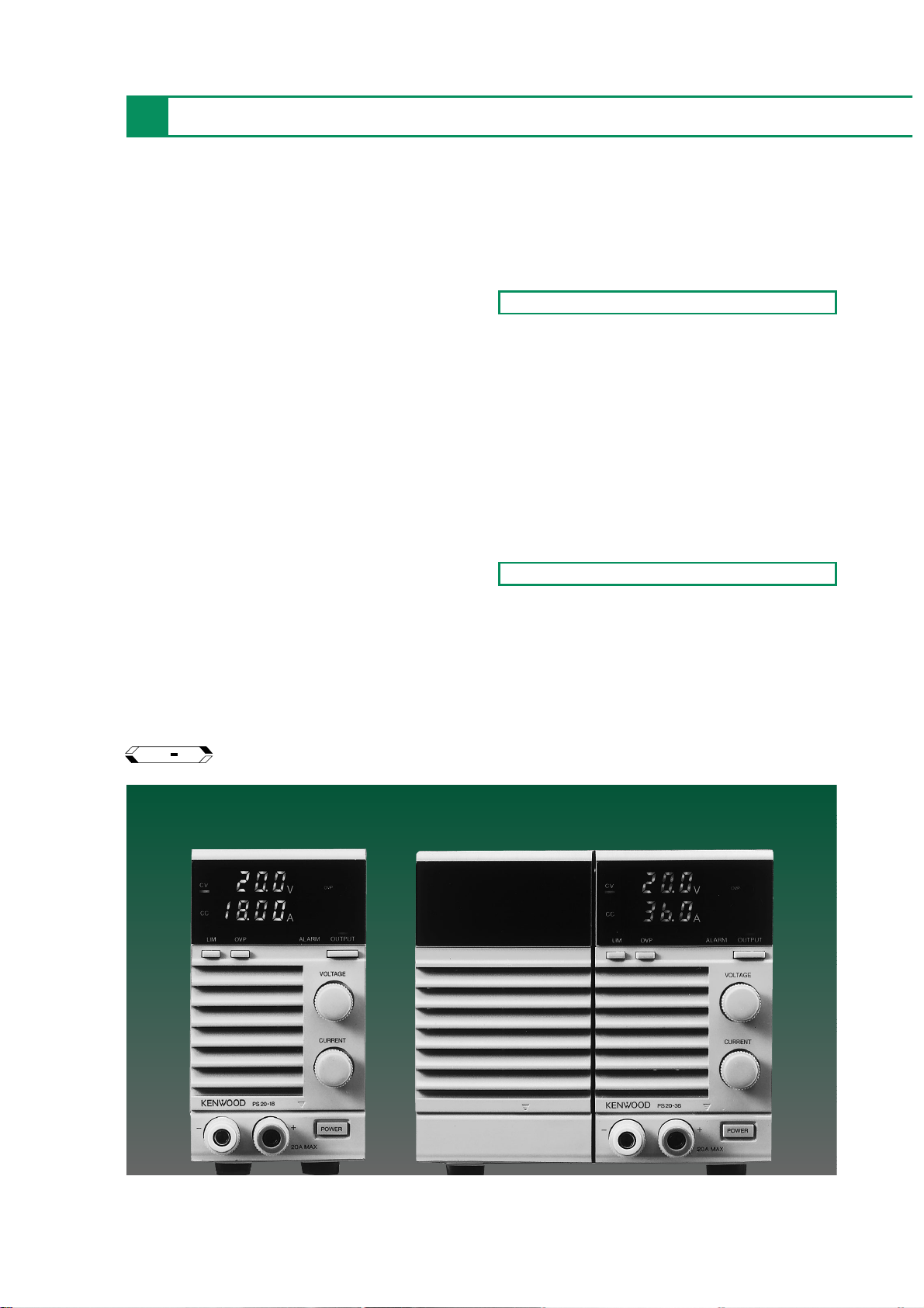
The PS Series power supplies are DC constant-voltage
(CV), constant-current (CC) power supplies based on
the variable switching method, featuring compact size,
light weight, excellent reliability and the variable
outputs. They have been designed as highly universal
stand-alone type models putting emphasis on the ease
of operation and safety and equipped with a variety of
protection functions. Three capacity types are
available including 360W, 720W, and 1080W and 13
kinds of variations are available by combining ranges of
0 to 6 V, 10 V, 20 V, 36 V and 60 V. Several versatile
applications are also provided including remote control
functions with GP-IB control capability (which is possible
when the optional GP-600 is used.)
Compact Size, Light Weight, High Efficiency
Thanks to the advanced switching method, the PS Series power
supplies are both compact and light , with less than half the mass
and volume of previous power supply models, resulting in an
excellent space factor and high efficiency
.Digital Display of Voltage and Current
Output voltage and current are indicated on 7-segment red LED
displays to allow easy checking.
PS SERIES
Regulated DC Power Supplies
6V/60A
PS6-60
PS10-35
PS36-10
PS60-6
6V/120A
10V/35A 10V/70A
36V/10A 36V/20A
60V/6A 60V/12A
PS6-120
PS10-70
20V/18A
PS20-18
20V/36A
PS20-36
20V/54A
PS20-54
PS36-20
36V/30A
PS36-30
PS60-12
60V/18A
PS60-18
GP IB
OPTION
OUTLINE
FEATURES
Page 2

REGULATED DC POWER SUPPLIES
PS SERIES
59
PS SERIES
REGULATED DC POWER SUPPLIES
Safety
(Fail-Safe Function)
For safety, the switching operation is stopped (output off status)
and the AC power relay is interrupted while a protection function
is operating.
●Output over-voltage protection (OVP)
When the output voltage exceeds the OVP setting value, the
switching operation (oscillation) is stopped and the output is
turned off.
●Output over-current protection (OCP)
Increase in the output current to 110% or more of the rated cur rent
is detected by a protection circuit, which stops the switching
operation and interrupts the AC power relay.
● Over-heat protection (OHP)
When the heat sink temperature reaches about 100℃ , the
switching operation is stopped and the AC power relay is
interrupted.
●Input power abnormality protection
In case of input over-voltage, input voltage drop or an over-current
due to internal abnormality, the switching operation is stopped
and the output is turned off.
●Alarm (power abnormality) signal
When the output over-current, input over-voltage or input overcurrent is detected, when the over-heat protection circuit is
activated or when the power is switched off, an alarm signal is
generated to turn the output off and interrupt the AC power relay.
●Power relay off signal
When trouble occurs on the user side, etc., the power relay is
interrupted by an external signal.
(Rush current protection circuit)
The rush current protection circuit is activated at the moment of
the power is switched on to reduce the input surge current.
GP-IB System Compatibility
In addition to the output voltage and current control capabilities
and status signal outputs, the output on/off, power on/of f control
and remote/local switches are provided. The GP-IB control is also
possible optionally (when the optional GP-600 is combined.)
Wide Applications
Control operations include control by an external voltage or
resistance of the output voltage and current.
Low Noise
The temperature-sensitive fan motor reduces the rotation speed
when the load is light or the ambient temperature is low to prevent
noise.
Front Air Intake
The forced air cooling system intakes air through the front panel
and increases the packing density in case the power supply is
mounted in a device or rack. The front grill incorporate an air filter
to improve dust protection.
PS6-60
PS10-35
PS20-18
PS36-10
PS60-6
PS6-120
PS10-70
PS20-36
PS36-20
PS60-12
PS20-54
PS36-30
PS60-18
Page 3
REGULATED DC POWER SUPPLIES
60
Power Switch
To enhance the safety of the power supply, the protect function
based on an AC power relay is provided separately from the power
switch. The AC power relay can be turned on/of f from a external
signal while leaving the power switch in the on position.
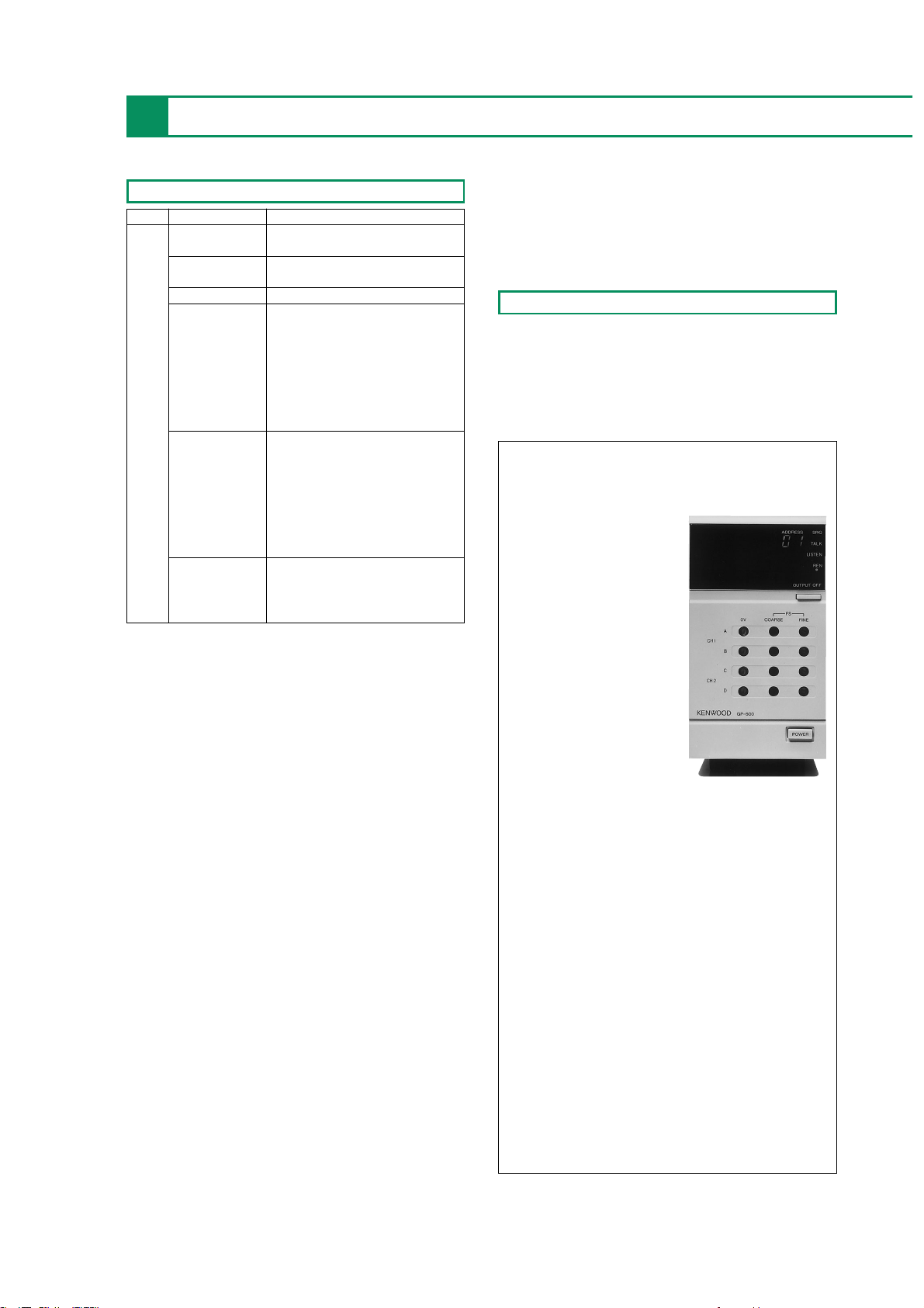
GP-IB Adapter for expanding the PS Series to a
GP-IB System, with 12 bits 4 built-in D/As.
GP-IB Adapter for PS Series Power Supplies
Applications
●Reliability testing of electronic par ts. ●Semiconductor aging
systems.● Durability testing of rotary and drive equipment. ●
Operation testing of HIC, etc. ● Testing of board, packaging unit or
electrical parts. ● Alternative to a batter y. ●Secondary batter y
testing.●Production or plating of electrolytic capacitors. ● LCD
aging systems.
Function
OVP Presetting
Pressing the OVP switch displays the OVP (Over Voltage
Protector) trip voltage on the voltmeter. This lets you perform
setting and verification without interrupting operation, even while
the output is on.
Digital Display
A bright, easy-to-read red LED shows the voltage and current
simultaneously. The voltage can be measured in 3-1/2 digits (autoranging) with a maximum display resolution of 10 mV with all
models. The current can be measured in 3-1/2 digits (autoranging) with a maximum display resolution of 10 mA with models
with rated currents below 50 A, and in 3-1/2 digits with a
maximum display resolution of 100 mA with models with rated
currents of 50 A or more (3-digit, 1 A resolution with the PS10-
210).
Output Switch
The output switch uses an electronic switch system to eliminate
chattering or noise. The switch is set automatically to off when
power is switched on so that unexpected output is not produced.
The output can be fixed to on or the output on/off switching can
be remote controlled with an external signal according to the DIP
switch selection.
Limit Switch
Pressing the LIMIT switch displays the constant voltage setting
value on the voltmeter and the constant current setting value
(current limiting value) on the ammeter. This makes setting and
verification possible without interruption, even while the output is
on.
Switch Mode Description
POWER SELECT Remote/local switching of AV power
relay on/off.
OUTPUT SELECT Remote/local switching of output
on/off.
OUTPUT SELECT Switching for fixing output to on.
Remote/local switching of output
voltage, voltage/resistance mode
selection for remote control.
CV.CONTROL
● Control by an external voltage
SELECT ● Control by an external resistance
(Normal mode)
S1 ● Control by an external resistance
(Fail-safe mode)
Remote/local switching of output
current, voltage/resistance mode
selection for remote control.
CC.CONTROL
● Control by an external voltage
SELECT ●Control by an external resistance
(Normal mode)
[●Control by an external resistance
(Fail-safe mode)]
Compensation for the resistance due
REMOTE SENSING
to load lines, and the voltage drop or
stability degradation due to contact
resistance.
●The PS Series control functions are implemented according to rear panel
control switch S1 and terminals J1 and J2. The specification inside【】
is possible by special order.
GP-600
【GP-600 Specifications】
GP-IB
Electrical specifications
: conformsto IEEE488.1-1978
Mechanical specifications
: conforms to IEEE488.1-1978
Interface function
: SH1, AH1, T6, L3, SR1, RL1,
PP0, DC1, DT1, C0
Address : Addresses 0 to 30 can be set
using an address switch.
Listen-only mode
: Can be set with L-ONLY switch
Transmission delimiter selection
: Can be set with the EOI/CR.LF
switch
Output on/off function:
:
Output can be off by manually with
the OUTPUT OFF key.
Service request function
:GP-IB command error, GP-IB
parameter error, OVP function
and alarm functions (OCP,
OTP and POWER cut), CV
function, CC function and
OUTPUT OFF key
Analog Output
Output voltage range
:
0 to +10V (A, B Output/CH1)
:
0 to +10V (C, D Output/CH2)
Full scale voltage range
: +10V ±15% (A, B Output/CH1)
: +10V ±15% (C, D Output/CH2)
Maximum output current
: 3mA
(A, B Output/CH1)
: 3mA
(C, D Output/CH2)
D/A converter resolution
12bit, 0.025% (2.4mV) (A, B Output/CH1)
12bit, 0.025% (2.4mV) (C, D Output/CH2)
Setting accuracy
:
0.0275% (A, B Output/CH1)
: 0.0275% (C, D Output/CH2 )
Output ripple (10Hz to 1MHz)
:
300µVrms
(A, B Output/CH1)
: 300µVrms
(C, D Output/CH2)
Supply voltage regulation (±10% fluctuate)
:
1.5mV
(A, B Output/CH1)
: 1.5mV
(C, D Output/CH2)
Temperature coefficient
: 50ppm/°C (Typ)
(A, B Output/CH1)
: 50ppm/°C (Typ)
(C, D Output/CH2)
Rise time
(10 to 90%, 10kΩ load)
:
100µs or less (A, B Output/CH1)
: 100µs or less (C, D Output/CH2)
Digital I/O
Control signal
Output ON/OFF
: TTL level Low (ON)/High (OFF)
Power・Relay ON/OFF
: TTL level Low (ON)/High (OFF)
Status signal
CV function (SRQ)
: TTL level Low (CV)/High (no change)
CC function (SRQ)
: TTL level Low (CC)/High (no change)
Alarm
ON(SRQ)
: TTL level Low (ON)/High
Power ON/OFF : Low(ON)
OVP ON (SRQ) : Low(ON)
Temperature/humidity for characteristics
in spec. : 0°C to 40 °C, 80% or less
Power source
: 100V±10 %, 120V/220V/240V
(250Vmax) AC,
(internally switchable)
Power consumption
: 10W
Case dimensions
: 70 (W)
×124 (H)×351 (D)
Weight : 2.5kg
Accessories : Instruction manual
×1
20pin flat cable
×2
Page 4
REGULATED DC POWER SUPPLIES
AC Power ON/OFF Control
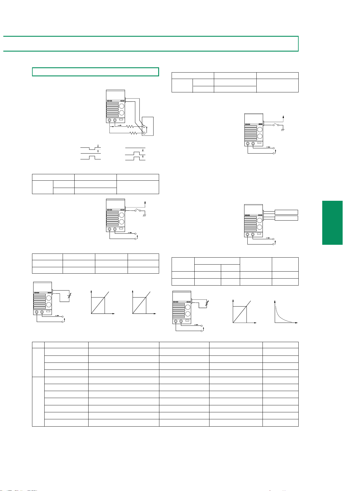
The power protection device (AC power relay) can be controlled on
/off from an exter nal signal (provided that the power switch is on).
CV/CC Monitoring
●A monitoring output from about 0 V to 1/10 the rated voltage
can be output with respect to the output voltage from 0 V to the
rated voltage.
●A monitoring output from about 0 V to 10 V can be output with
respect to the output current from 0 A to the rated cur rent.
Control by an External resistance of Output Voltage and Current
61
Remote Sensing
This function prevents the voltage
drop which is caused by the load
connection resistance and the
stability degradation caused by the
contact resistance, and compensates
for the voltage drop of up to 1 V
per path provided that the output
terminal voltage is within the rated
voltage.
Output ON/OFF Control
The output can be turned on/off with
an external signal. The output can also
be fixed to on while power is on.
Control by an External Voltage of Output Voltage and Current
Functions for system power supply
PS SERIES
REGULATED DC POWER SUPPLIES
PS SERIES
Cont. item Control Resistance Current flowing Input Common
Normal Fail safe
a resistance
Output voltage 0 to approx.10kΩ
∞ to 0Ω
Approx. 1mA or less
+S terminal
Output current 0 to approx.10kΩ
【∞ to 0Ω】
Approx. 1mA or less
+S terminal
Items Control contents Input control signal In/Out Common Connector
Output voltage Output voltage
0 to 10V/0 to10kΩ, ∞ to 0Ω
+S terminal J
1
Output current Output current
0 to 10V/0 to10kΩ, ∞ to 0Ω
+S terminal J
1
Output ON/OFF Output ON Photo diode ON Floating
(Community common)
J
1
Power ON/OFF AC power relay ON Photo diode ON Floating
(Community common)
J
1
CV. mode signal At CV operation Photo transistor ON Floating
(Community common)
J
1
CC.mode signal At CC operation Photo transistor ON Floating
(Community common)
J
1
Power on signal At power on Photo transistor ON Floating
(Community common)
J
1
OVP signal At OVP operation Photo transistor ON Floating
(Community common)
J
1
Alarm signal At OCP, OHP operation, power of f Photo transistor ON Floating
(Community common)
J1/J
2
Output voltage monitor
For output 0V to rated voltage 0V to 1/10 ×rated voltage +S terminal J
2
Output current monitor
For output 0A to rated current
0V to 10V
+S terminal
J
2
Input signal Output signal
* Each of the Floating (Common) input/output signals passes through a photo coupler and uses a diode input and open collector output. Their common
terminal is common.
* The alarm signal is also output during the operation of the input current protection circuit or input over-voltage protection circuit.
Applications - Remote Control Operations
Control item Control signal Input Common
Output
ON Photo diode ON
Floating
OFF Photo diode OFF
(Community common)
Control item Control Voltage Input impedance
Input Common
Output voltage 0 to Approx. 10V Approx. 10kΩ +S terminal
Output current 0 to Approx. 10V Approx. 10kΩ +S terminal
Control item Control signal Input Common
AC power
ON Photo diode ON
Floating
relay OFF Photo diode OFF
(Community common)
−
EO
Without sensing
E
L
EO
IO
2r×IO
J2
+S
−S
+
IO
With sensing
EL
EO
IO
J1
r
r E
IO
Load
2r×IO
L
Vcc
J1
IO
EO
Vcc
EO
J2
CV. Monitor
CC. Monitor
IO
EO
J1
IO
+
−
EO
E1/E2
Output
voltage
EO
External voltage
(0 to10V)
E1
Output
current
IO
External voltage
(0 to10V)
IO
EO
External resistance
(0 to10k)
R1
Output
current
Output
voltage
E2
+
−
J1
R1/R2
Output
current
Output
IO
voltage
EO
IO
EO
External resistance
(0 to10k)
R2
Page 5
Powersource 85 to 132V /170 to 250V
AC 50 to 60Hz
Displayinstruments
Voltmeter
Display 3-1/2 digits red LED
Accuracy 0.1%rdg±2digits (23±5℃)
Temperature coefficient
±100ppm/℃ (0 to 50℃)
Ammeter
Display 3-1/2 digits red LED
Accuracy 0.5%rdg±3digits (23±5℃)
Temperature coefficient
±200ppm/℃ (0 to 50℃)
Protection
Overvoltage protection The power relay is tripped when the
output voltage is exceeded by approx.
110%. of the rated voltage.
Overcurrent protection The power relay is tripped when the
output current is approx. 110% to
130% of the rated current.
Overheating Protection The power relay is tripped when the
temperature of the heat sink is
approx. 100±5°C or more.
Thermal fuse Built-in thermal fuse
Input fuse Cut off the power relay
REGULATED DC POWER SUPPLIES
62
Common Specifications
Environmental condition
Temperature/humidity
for operation 0 to 50℃/30 to 80%RH
Temperature/humidity
for storage −20 to 70℃/20 to 80%RH
Cooling system Forced air (fan), front air intake type.
Functions Automatic output switch resetting,
voltage/current limit switch, preset
OVP
Casedimensions
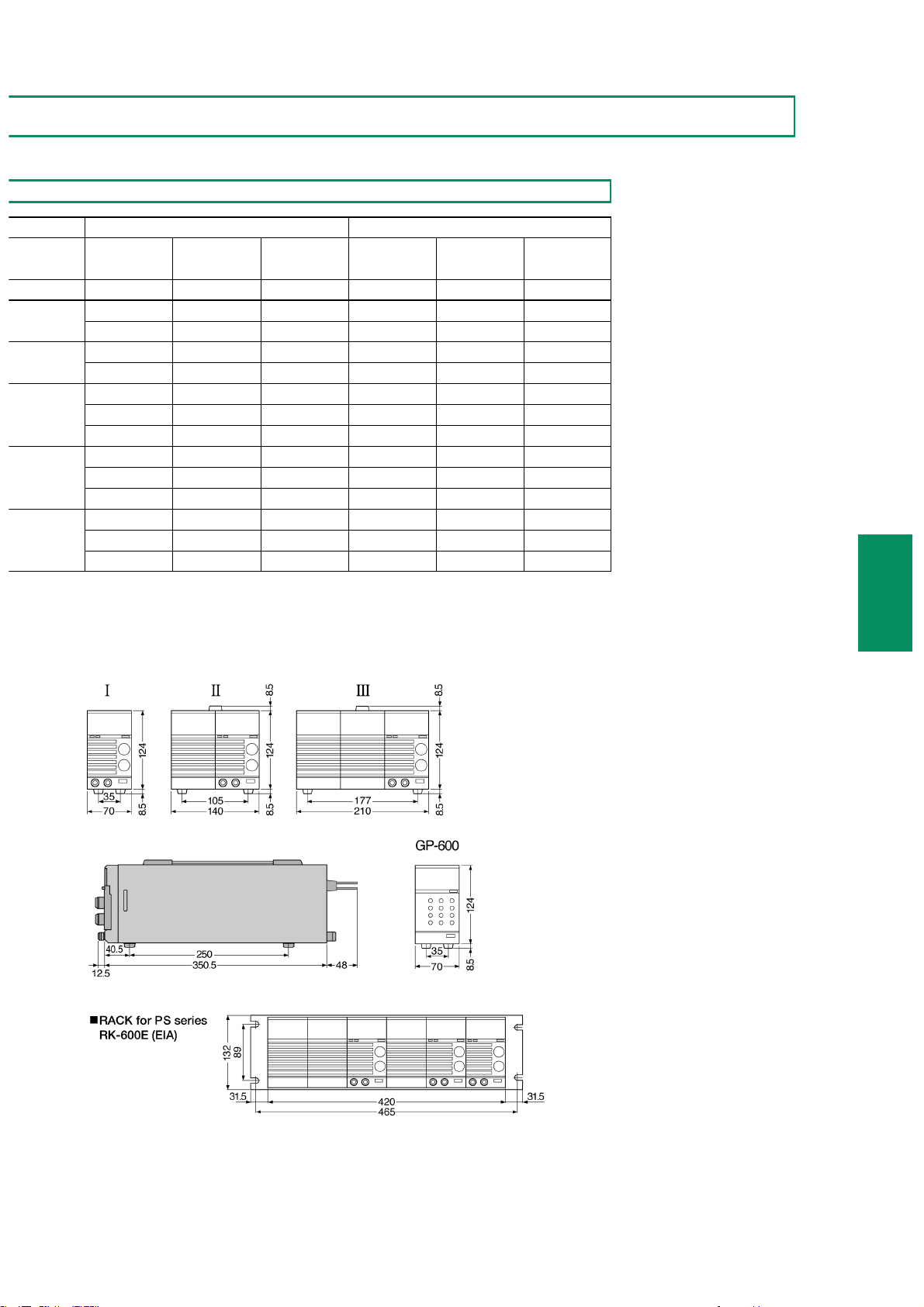
Type I 70 (W) × 124 (H) × 350.5 (D) mm
Type II 140 (W) × 124 (H) × 350.5 (D) mm
Type III 210 (W) × 124 (H) × 350.5 (D) mm
Accessories 2.5m AC cable × 1
SPECIFICATIONS
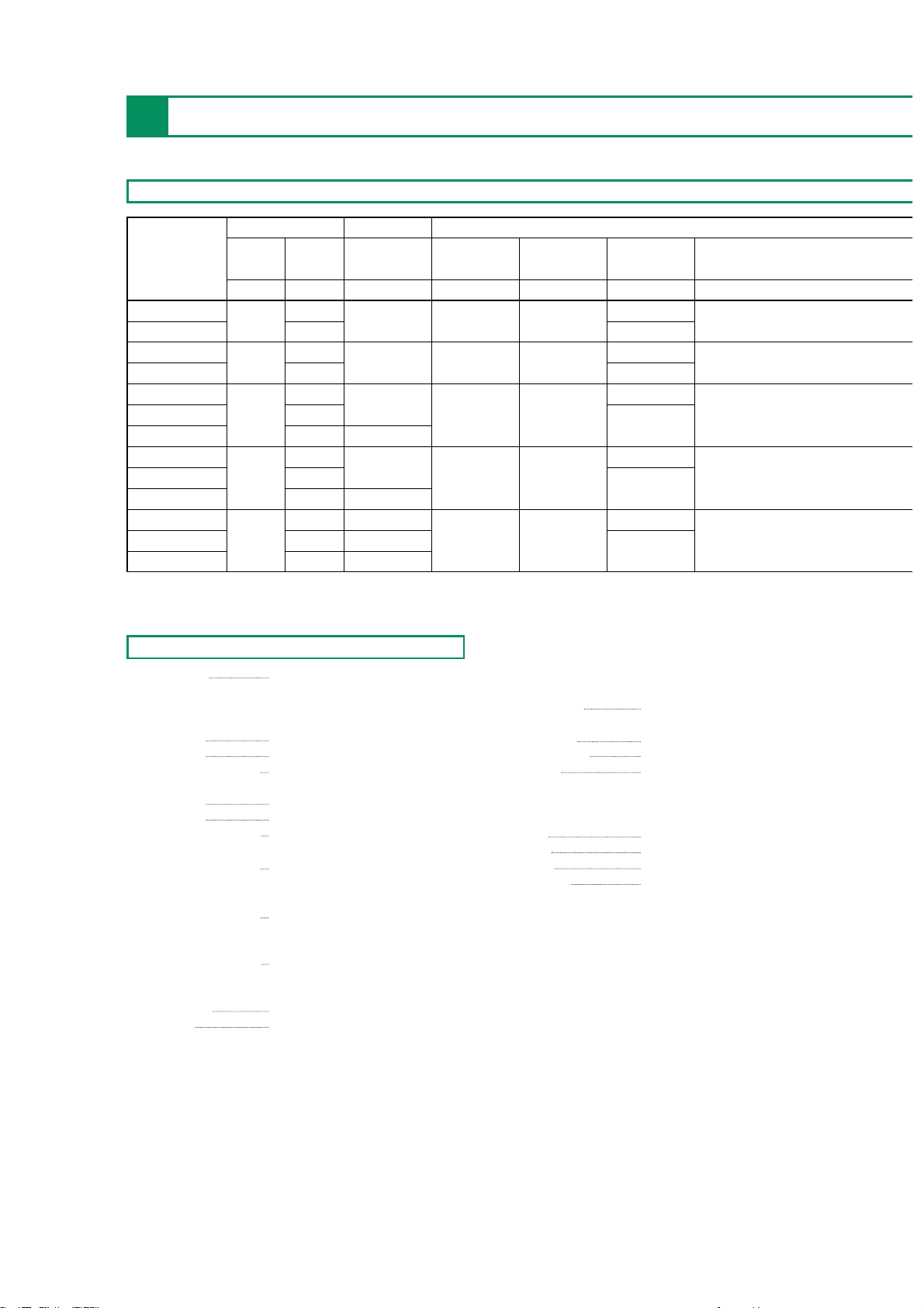
Output CV (constant-voltage) characteristic
Model
CV CC Ripple* Line regulation Load regulation
Transient Rise time/
response** Fall time
VAmV rms 0.05%
+mV 0.1% +mV m sec m sec (Full loaded)
PS6-60
0 to 6
0 to 60
10 5 5
1
80/150
PS6-120 0 to 120 2
PS10-35 0 to 35 1
PS10-70
0 to 10
0 to 70
10 5 5
2
80/150
PS20-18 0 to 18
10
1
PS20-36 0 to 20 0 to 36 5 5 80/150
PS20-54 0 to 54 15
2
PS36-10 0 to 10 1
PS36-20 0 to 36 0 to 20 10 5 5
2
80/150
PS36-30 0 to 30 15
PS60-6 0 to 6 10 1
PS60-12 0 to 60 0 to 12 15 5 5 80/150
PS60-18 0 to 18 20
2
Page 6
REGULATED DC POWER SUPPLIES
63
PS SERIES
REGULATED DC POWER SUPPLIES
PS SERIES
*1: Between 20 Hz and 1 MHz.
*2: The time taken by the output
voltage to return to within 0.1%
+10 mV of the set value when
the output current is varied from
20% to 100% at 50% to 100% of the
rated output voltage.
*3: Measured when the output
voltage is between 1% and 100%
of the rated voltage.
■FigureofCasedimensions
■ 1
RB-600A (1/2 rack width)
RB-600B (1/3 rack width)
RB-600C (1/6 rack width)
CC (constant-current) characteristic Others
Ripple*** Line regulation Load regulation Input Current Case dimensions Weight
mA rms 0.2%
+mA 0.2%+mA
AC (100/200V)A
Type kg (approx.)
120 5 5 8/5 I 3.0
260 10 10 16/10 II 5.5
70 5 5 8/5 I 3.0
160 10 10 15/9 II 5.5
40 5 5 8/5 I 3.0
92 10 10 15/9 II 5.5
120 15 15 22/13 III 7.0
20 5 5 8/5 I 3.0
60 10 10 15/9 II 5.5
80 15 15 22/13 III 7.0
12 5 5 8/5 I 3.0
44 10 10 15/9 II 5.5
55 15 15 22/13 III 7.0
 Loading...