

Page 1

INSTRUCTION MANUAL
VHF FM TRANSCEIVER
TK-2400
UHF FM TRANSCEIVER
TK-3400
B62-2478-20 (K)
Page 2

THANK YOU
We are grateful for your purchase of this KENWOOD product
and welcome you to the Business Radio Service (BRS).
Your KENWOOD 2-way Business Radio is called a “transceiver”,
meaning “transmitter & receiver”. We believe this easy-touse transceiver will provide you with dependable and reliable
communications. This KENWOOD transceiver is a precision
device. Treat it with care, and you will enjoy years of reliable
operation.
FEATURES
• 4 (K type) or 16 (K2 type) channels with 27 VHF (TK-2400) or
90 UHF (TK-3400) operating frequencies and each channel
can be set up with a QT tone or DQT code allowing you to
ignore unwanted calls.
• Built in voice scrambler gives you complete privacy for your
conversations.
• Hands free operation when using an optional headset.
• Voice announcement lets you know which channel you have
selected and which settings you have made when reassigning
key functions and channel settings.
OPERATING CONDITIONS
Condition TK-2400 TK-3400
Open locations
(no obstructions)
In steel/ concrete
reinforced buildings
In high rises Up to 13 fl oors Up to 20 fl oors
Up to 6 miles (9.6 km)
Up to 220,000 square
feet (20,440 m
2
)
Up to 250,000 square
feet (23,220 m2)
Note: The listed ranges are based on fi eld testing and may vary with
your operating conditions and individual transceiver.
© 2015
Page 3

FCC LICENSE INFORMATION
Your KENWOOD transceiver operates on communications
frequencies which are subject to FCC (Federal
Communications Commission) Rules & Regulations. FCC
Rules require that all operators using Private Land Mobile
radio frequencies obtain a radio license before operating their
equipment. Application for license must be made on FCC form
601, schedules D and H, and Remittance form 159.
FAX: Forms can be obtained by fax from the FCC Fax-OnDemand system. Call 1-202-418-0177 from your fax machine
and request document number 000601 for the form, schedules,
and instructions.
MAIL: Forms can be ordered by telephone, and will be sent to
you by fi rst class mail. Call the FCC Forms Hotline at
1-800-418-FORM (1-800-418-3676).
INTERNET: Form 601 and instructions can be downloaded
from the FCC Forms website at
http://www.fcc.gov/formpage.html
Before fi lling out your Form 601 application Technical Data
section, you must decide on which frequencies you will operate.
See the frequency charts on pages 14 and 15.
QUESTIONS? Call the FCC for license application questions
at 1-888-CALL-FCC (1-888-225-5322).
i
Page 4

One or more of the following statements may be
applicable:
FCC WARNING
This equipment generates or uses radio frequency energy. Changes
or modifi cations to this equipment may cause harmful interference
unless the modifi cations are expressly approved in the instruction
manual. The user could lose the authority to operate this equipment if
an unauthorized change or modifi cation is made.
INFORMATION TO THE DIGITAL DEVICE USER REQUIRED BY THE
FCC
This equipment has been tested and found to comply with the limits for
a Class B digital device, pursuant to Part 15 of the FCC Rules. These
limits are designed to provide reasonable protection against harmful
interference in a residential installation.
This equipment generates, uses and can generate radio frequency
energy and, if not installed and used in accordance with the instructions,
may cause harmful interference to radio communications. However,
there is no guarantee that the interference will not occur in a particular
installation. If this equipment does cause harmful interference to radio or
television reception, which can be determined by turning the equipment
off and on, the user is encouraged to try to correct the interference by
one or more of the following measures:
Reorient or relocate the receiving antenna.
Increase the separation between the equipment and receiver.
Connect the equipment to an outlet on a circuit different from that
to which the receiver is connected.
Consult the dealer for technical assistance.
ATTENTION:
The RBRC Recycle seal found on KENWOOD lithiumion (Li-ion) battery packs indicates KENWOOD’s
voluntary participation in an industry program to collect
and recycle Li-ion batteries after their operating life
has expired. The RBRC program is an alternative to
disposing Li-ion batteries with your regular refuse or in
municipal waste streams, which is illegal in some areas.
For information on Li-ion battery recycling in your area, call (toll free)
1-800-8-BATTERY (1-800-822-8837).
KENWOOD’s involvement in this program is part of our commitment to
preserve our environment and conserve our natural resources.
ii
Page 5

Terminal Descriptions
Speaker/ Microphone Jacks
It is possible to use a resin-based cover for the Speaker/ Microphone jacks.
NO. Name Description Impedance I/O
1 PTT / RXD
2 MIC External MIC Input 1.8 k
3 MICIN Internal MIC Output 1.8 k
4 OPTDET External Option Detect High Impedance I
5 5M 5V Output 100
6 AE GND GND
7 TXD Serial Data Output CMOS O
8 NC No Connection
9 SPO Audio Input 8
10 SPI Received Audio Output 8
Antenna Terminal
50 impedance
Battery Terminal
The battery terminal uses a spring plate.
The negative terminal connects to the chassis ground.
The battery is mounted on the rear side of the transceiver using a latch
mounting method.
External PTT Input / Serial
Data Input
CMOS I
−−
I
O
O
−
I
O
Firmware Copyrights
The title to and ownership of copyrights for fi rmware embedded in
KENWOOD product memories are reserved for JVC KENWOOD
Corporation.
iii
Page 6

NOTICES TO THE USER
Government law prohibits the operation of unlicensed radio
◆
transmitters within the territories under government control.
Illegal operation is punishable by fi ne and/or imprisonment.
◆
Refer service to qualifi ed technicians only.
◆
Safety: It is important that the operator is aware of, and
understands, hazards common to the operation of any
transceiver.
PRECAUTIONS
• Do not charge the transceiver and battery pack when they are wet.
• Ensure that there are no metallic items located between the
transceiver and the battery pack.
• Do not use options not specifi ed by KENWOOD.
• If the die-cast chassis or other transceiver part is damaged, do not
touch the damaged parts.
• If a headset or headphone is connected to the transceiver, reduce
the transceiver volume. Pay attention to the volume level when
turning the squelch off.
• Do not place the microphone cable around your neck while near
machinery that may catch the cable.
• Do not place the transceiver on unstable surfaces.
• Ensure that the end of the antenna does not touch your eyes.
• When the transceiver is used for transmission for many hours, the
radiator and chassis will become hot. Do not touch these locations
when replacing the battery pack.
• Do not immerse the transceiver in water.
• Always switch the transceiver power off before installing optional
accessories.
• The charger is the device that disconnects the unit from the AC
mains line. The AC plug should be readily accessible.
• To dispose of batteries, be sure to comply with the laws and
regulations in your country or region.
iv
Page 7
Turn the transceiver power off in the following locations:
• In explosive atmospheres (infl ammable gas, dust particles,
metallic powders, grain powders, etc.).
• While taking on fuel or while parked at gasoline service stations.
• Near explosives or blasting sites.
• In aircrafts. (Any use of the transceiver must follow the instructions
and regulations provided by the airline crew.)
• Where restrictions or warnings are posted regarding the use of
radio devices, including but not limited to medical facilities.
• Near persons using pacemakers.
• Do not disassemble or modify the transceiver for any reason.
• Do not place the transceiver on or near airbag equipment while
the vehicle is running. When the airbag infl ates, the transceiver
may be ejected and strike the driver or passengers.
• Do not transmit while touching the antenna terminal or if
any metallic parts are exposed from the antenna covering.
Transmitting at such a time may result in a high-frequency burn.
• If an abnormal odor or smoke is detected coming from the
transceiver, switch the transceiver power off immediately,
remove the battery pack from the transceiver, and contact your
KENWOOD dealer.
• Use of the transceiver while you are driving may be against traffi c
laws. Please check and observe the vehicle regulations in your
area.
• Do not expose the transceiver to extremely hot or cold conditions.
• Do not carry the battery pack (or battery case) with metal objects,
as they may short the battery terminals.
• Danger of explosion if the battery is incorrectly replaced; replace
only with the same type.
• When operating the transceiver in areas where the air is dry, it is
easy to build up an electric charge (static electricity). When using
an earphone accessory in such conditions, it is possible for the
transceiver to send an electric shock through the earphone and to
your ear. We recommend you use only a speaker/microphone in
these conditions, to avoid electric shocks.
v
Page 8

Information concerning the battery pack:
The battery pack includes fl ammable objects such as organic
solvent. Mishandling may cause the battery to rupture
producing fl ames or extreme heat, deteriorate, or cause other
forms of damage to the battery. Please observe the following
prohibitive matters.
• Do not disassemble or reconstruct battery!
The battery pack has a safety function and protection circuit to
avoid danger. If they suffer serious damage, the battery may
generate heat or smoke, rupture, or burst into fl ame.
• Do not short-circuit the battery!
Do not join the + and – terminals using any form of metal (such
as a paper clip or wire). Do not carry or store the battery pack in
containers holding metal objects (such as wires, chain-necklace or
hairpins). If the battery pack is short-circuited, excessive current will
fl ow and the battery may generate heat or smoke, rupture, or burst
into fl ame. It will also cause metal objects to heat up.
• Do not incinerate or apply heat to the battery!
If the insulator is melted, the gas release vent or safety function is
damaged, or the electrolyte is ignited, the battery may generate
heat or smoke, rupture, or burst into fl ame.
• Do not leave the battery near fi re, stoves, or other heat
generators (areas reaching over 80°C/ 176°F)!
If the polymer separator is melted due to high temperature, an
internal short-circuit may occur in the individual cells and the
battery may generate heat or smoke, rupture, or burst into fl ame.
• Do not immerse the battery in water or get it wet by other
means!
If the battery’s protection circuit is damaged, the battery may
charge at extreme current (or voltage) and an abnormal chemical
reaction may occur. The battery may generate heat or smoke,
rupture, or burst into fl ame.
• Do not charge the battery near fi re or under direct sunlight!
If the battery’s protection circuit is damaged, the battery may
charge at extreme current (or voltage) and an abnormal chemical
reaction may occur. The battery may generate heat or smoke,
rupture, or burst into fl ame.
vi
Page 9

• Use only the specifi ed charger and observe charging
requirements!
If the battery is charged in unspecifi ed conditions (under high
temperature over the regulated value, excessive high voltage or
current over regulated value, or with a remodeled charger), it may
overcharge or an abnormal chemical reaction may occur. The
battery may generate heat or smoke, rupture, or burst into fl ame.
• Do not pierce the battery with any object, strike it with an
instrument, or step on it!
This may break or deform the battery, causing a short-circuit. The
battery may generate heat or smoke, rupture, or burst into fl ame.
• Do not jar or throw the battery!
An impact may cause the battery to leak, generate heat or smoke,
rupture, and/or burst into fl ame. If the battery’s protection circuit
is damaged, the battery may charge at an abnormal current (or
voltage), and an abnormal chemical reaction may occur. The
battery may generate heat or smoke, rupture, or burst into fl ame.
• Do not use the battery pack if it is damaged in any way!
The battery may generate heat or smoke, rupture, or burst into
fl ame.
• Do not solder directly onto the battery!
If the insulator is melted or the gas release vent or safety function
is damaged, the battery may generate heat or smoke, rupture, or
burst into fl ame.
• Do not reverse the battery polarity (and terminals)!
When charging a reversed battery, an abnormal chemical reaction
may occur. In some cases, an unexpected large amount of current
may fl ow upon discharging. The battery may generate heat or
smoke, rupture, or burst into fl ame.
• Do not reverse-charge or reverse-connect the battery!
The battery pack has positive and negative poles. If the battery
pack does not smoothly connect with a charger or operating
equipment, do not force it; check the polarity of the battery. If the
battery pack is reverse-connected to the charger, it will be reversecharged and an abnormal chemical reaction may occur. The
battery may generate heat or smoke, rupture, or burst into fl ame.
vii
Page 10

• Do not touch a ruptured and leaking battery!
If the electrolyte liquid from the battery gets into your eyes, wash
your eyes with fresh water as soon as possible, without rubbing
your eyes. Go to the hospital immediately. If left untreated, it may
cause eye-problems.
• Do not charge the battery for longer than the specifi ed time!
If the battery pack has not fi nished charging even after the
regulated time has passed, stop it. The battery may generate heat
or smoke, rupture, or burst into fl ame.
• Do not place the battery pack into a microwave or high
pressure container!
The battery may generate heat or smoke, rupture, or burst into
fl ame.
• Keep ruptured and leaking battery packs away from fi re!
If the battery pack is leaking (or the battery emits a bad odor),
immediately remove it from fl ammable areas. Electrolyte leaking
from battery can easily catch on fi re and may cause the battery to
generate smoke or burst into fl ame.
• Do not use an abnormal battery!
If the battery pack emits a bad odor, appears to have different
coloring, is deformed, or seems abnormal for any other reason,
remove it from the charger or operating equipment and do not use
it. The battery may generate heat or smoke, rupture, or burst into
fl ame.
viii
Page 11

CONTENTS
UNPACKING AND CHECKING EQUIPMENT .......................... 1
PREPARATION .......................................................... 2
ORIENTATION ........................................................... 6
BASIC OPERATIONS ................................................... 8
VOICE OPERATED TRANSMISSION (VOX) .......................... 9
BACKGROUND OPERATIONS ........................................ 10
CHANNEL SETUP MODE ..............................................11
KEY ASSIGNMENT MODE ............................................20
TROUBLESHOOTING GUIDE .........................................25
ALL RESET MODE ..................................................... 26
UNPACKING AND CHECKING EQUIPMENT
Carefully unpack the transceiver. If any of the items listed
below are missing or damaged, fi le a claim with the carrier
immediately.
SUPPLIED ACCESSORIES
• Antenna ..................................................................................1
• Battery charger/ AC adapter (KSC-35S) ................................1
• Li-ion Battery pack (KNB-45L) ................................................1
• Speaker/ microphone jack cover ............................................1
• Speaker/ microphone locking bracket ..................................... 1
• Belt clip (KBH-10) ...................................................................1
• Screw (
• Warranty card ......................................................................... 1
• Instruction manual ..................................................................1
Note: Refer to "PREPARATION" for accessory installation
instructions.
M3 x 8 mm) ..................................................................2
1
Page 12
PREPARATION
INSTALLING THE ANTENNA
Antenna
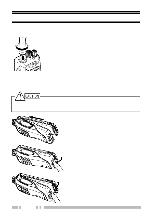
INSTALLING/ REMOVING THE BATTERY PACK
◆ Do not short the battery terminals or dispose of the battery by fi re.
◆ Never attempt to remove the casing from the battery pack.
Screw the antenna into the connector on
the top of the transceiver by holding the
antenna at its base and turning it clockwise
until secure.
Note: The antenna is neither a handle, a
key ring retainer, nor a speaker/ microphone
attachment point. Using the antenna in these
ways may damage the antenna and degrade
your transceiver’s performance
1 Align the battery pack with the
back of the transceiver, then
press the battery pack and
transceiver fi rmly together until
the release latch on the base of
the transceiver locks.
2 To remove the battery pack, lift
the safety catch on the base of
the transceiver, then press the
release latch underneath the
safety catch.
3 While pressing the release latch,
pull the battery pack away from
the transceiver.
2
Page 13
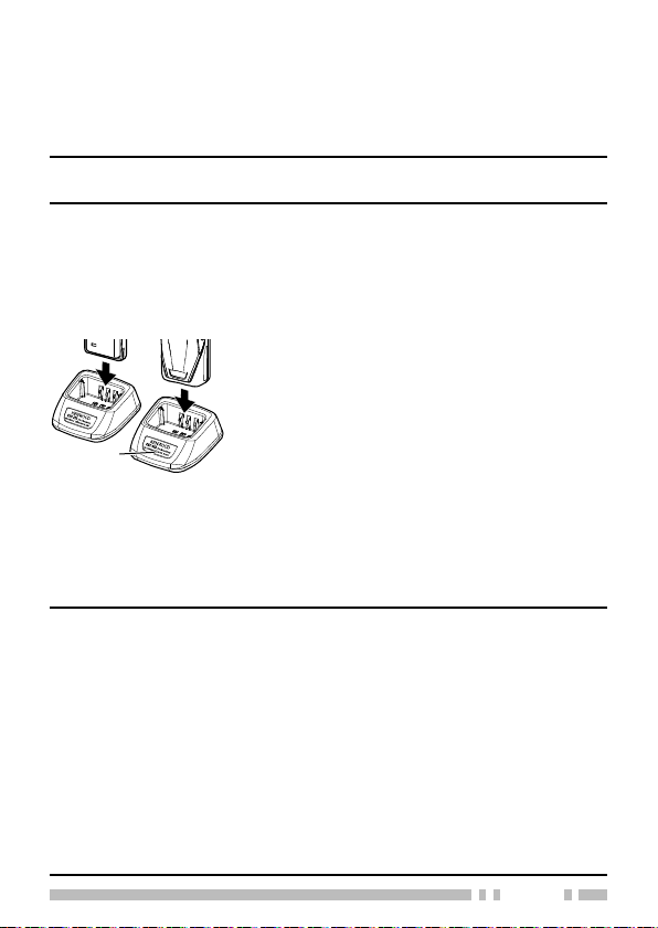
CHARGING THE BATTERY PACK
The battery pack is not charged at the factory; charge it before
use. Average battery pack life (calculated using 5% transmit
time, 5% receive time, and 90% standby time) is 17 hours.
ATTENTION: Always switch OFF a transceiver equipped with a
battery pack before inserting the transceiver into the charger.
1 Plug the AC adapter cable into the jack located on the rear
of the charger.
2 Plug the AC adapter into an AC outlet.
3 Slide a battery pack or a transceiver equipped with a battery
pack into the charging slot of the charger.
• Make sure the metal contacts of the battery
pack mate securely with the charger
terminals.
• The indicator lights red and charging
Indicator
4 When charging is completed, the indicator lights green.
Remove the battery pack or the transceiver from the
charging slot of the charger.
• It takes approximately 3 hours to charge the battery pack.
• When the charger will not be used for a long time, unplug the AC
adapter from the AC outlet.
Note:
◆ When the indicator blinks red, the battery pack is either
defective or the battery pack contacts are not properly mated
with those of the charger.
◆ When the indicator fl ashes green and orange, the battery pack
has not satisfi ed the charging start temperature. Remove the
battery pack from the charger and wait until it reaches a normal
temperature before charging it again.
◆ The ambient temperature should be between 41°F and 104°F
(5°C and 40°C) while charging is in progress. Charging outside
this range may not fully charge the battery.
◆ The battery pack life is over when its operating time decreases even
though it is fully and correctly charged. Replace the battery pack.
begins.
3
Page 14
INSTALLING THE BELT CLIP
If necessary, attach the belt clip using
the two supplied M3 x 8 mm screws.
Note: If the belt clip is not installed, its
mounting location may get hot during
continuous transmission or when left
Belt clip
Do not use glue which is designed to prevent screw loosening when
installing the belt clip, as it may cause damage to the transceiver.
Acrylic ester, which is contained in these glues, may crack the
transceiver’s back panel.
sitting in a hot environment.
INSTALLING THE CAP OVER THE SPEAKER/
MICROPHONE JACKS
Install the cap over the speaker/ microphone jacks when not
using an optional speaker/ microphone.
Note: To keep the transceiver water resistant, you must cover the
speaker/ microphone jacks with the supplied cap.
1 Place the cap over the jacks so that the locking tabs
insert into the transceiver grooves.
2 While holding the cap in place, push it towards the
bottom of the transceiver until the tabs on the cap click
into place.
• To remove the cap, hold the top of the cap in place
with your fi nger while inserting a
2 mm or smaller fl at blade screwdriver under the
bottom of the cap. Slowly slide the screwdriver
in until its tip touches the tab inside the cap, then
gently pry the cap up (handle of screwdriver
moving away from the transceiver) to remove the
cap.
4
Page 15
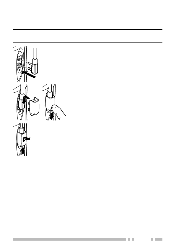
INSTALLING THE OPTIONAL SPEAKER/ MICROPHONE
(OR HEADSET)
Note: The transceiver is not fully water resistant when using a
speaker/ microphone or headset.
1 Insert the speaker/ microphone (or
headset ) plugs into the speaker/
microphone jacks of the transceiver.
2 Place the locking bracket over the
speaker/ microphone (or headset) plugs
so that the locking tabs insert into the
transceiver grooves.
• Push down on the locking bracket to
slide it into place.
3 While holding the locking bracket in
place, push it towards the bottom of the
transceiver until the tabs on the bracket
click into place.
• To remove the locking bracket, push
the bracket up from the base.
5
Page 16
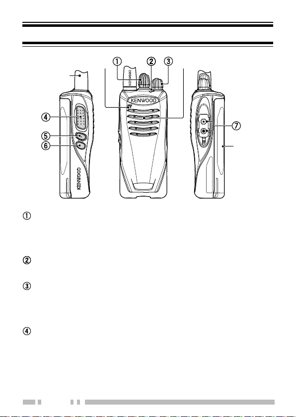
ORIENTATION
Microphone
Antenna
Speaker
Battery pack
Channel selector
Rotate to change the operating channel.
• To change the operating frequency or QT/DQT settings of a
channel, refer to “CHANNEL SETUP MODE” on page 11.
LED indicator
For the LED indicator status, refer to page 8.
Power switch/ Volume control
Turn clockwise to switch the transceiver ON. To switch the
transceiver OFF, turn counterclockwise until a click sounds.
Rotate to adjust the volume level.
PTT (Push to Talk) switch
Press and hold, then speak around the microphone area to
transmit.
6
Page 17

Side 1 key
Press to activate its programmable function.
The default setting is [None] (no function).
• For function descriptions and details on how to change the
function of the Side 1 key, refer to “KEY ASSIGNMENT MODE”
on page 20.
Side 2 key
Press to activate its programmable function.
The default setting is [None] (no function).
• For function descriptions and details on how to change the
function of the Side 2 key, refer to “KEY ASSIGNMENT MODE”
on page 20.
Speaker/ microphone jacks
Insert the Speaker/ microphone or Headset plug into this
jack.
7
Page 18
BASIC OPERATIONS
1 Turn the Power switch/ Volume control
clockwise to switch the transceiver power
ON.
• The LED indicator lights blue for 1 second
when turning the Power ON.
2 Rotate the Channel selector to select your
desired channel.
• When you receive an appropriate signal, you
will hear audio from the speaker. Adjust the
volume as necessary.
3 To make a call, press and hold the PTT
switch, then speak around the microphone
area using your normal speaking voice.
• Hold the microphone approximately 1.5 inches
(3 to 4 cm) from your lips.
4 Release the PTT switch to receive.
Note: When the battery pack voltage becomes too
low, the Low Battery Warning sounds an alert tone
every 30 seconds and the LED indicator blinks red.
LED Indicator Status
Indicator Color Meaning
Lights red Transmitting
Lights green Receiving a call
Blinks red Battery power is low while transmitting
Blinks green Scanning
Blinks red/orange
The selected channel has not been
programmed and cannot be used.
8
Page 19

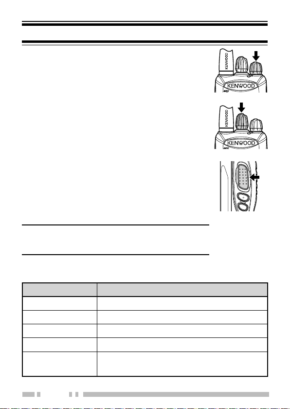
VOICE OPERATED TRANSMISSION (VOX)
VOX operation allows you to transmit hands-free. VOX can
only be used if you are using a supported headset. This
function can be turned off for specifi c channels.
To activate VOX and set the VOX Gain level, perform the
following steps:
1 Connect the headset to the transceiver .
• The VOX function does not activate when a headset is not
connected to the accessory terminal of the transceiver.
2 With the transceiver power OFF, press and hold the Side 1
key while turning the transceiver power ON.
3 Continue to hold the Side 1 key until a beep sounds.
• The LED indicator lights turn orange.
• When the Side 1 key is released, the transceiver will announces
the VOX Gain level (the default level is OFF, so, a double beep
sounds).
4 Press the Side 1 key to select the VOX Gain level of the radio
(from 1~10 or Off).
• Press the Side 2 key to enable or disable the VOX function for
the current channel (you can change this setting for each channel
by selecting a channel with the Channel selector). When turned
ON, a beep sounds. When turned OFF, a double beep sounds.
5 Press the PTT switch to save the setting.
• A beep will sound.
• The transceiver announces the new VOX Gain level.
6 Turn the transceiver power OFF and then ON again to
activate VOX.
Note:
◆ The transceiver will automatically return to normal operation if
no action is performed for 20 seconds.
◆ VOX Gain level 1 is the least sensitive and VOX Gain level 10 is
the most sensitive.
◆ If a headset is connected to the transceiver while the VOX
function is switched ON and the VOX Gain level is confi gured
to a higher, more sensitive level, louder received signals may
cause the transceiver to start transmission.
9
Page 20

BACKGROUND OPERATIONS
TIME-OUT TIMER (TOT)
The Time-out Timer prevent callers from using a channel for an
extended duration (60 seconds). If you continuously transmit
for the duration, transmission will stop and an alert tone will
sound. To stop the tone, release the PTT switch.
LOW BATTERY WARNING
While operating the transceiver, the Low Battery Warning
sounds an alert tone every 30 seconds and the LED indicator
blinks red when the battery needs recharged or replaced.
10
Page 21

CHANNEL SETUP MODE
This transceiver allows you to reprogram each of the channels
with different frequencies and QT (Quiet Talk)/ DQT (Digital
Quiet Talk) settings. The table below lists the default channel
settings.
Channel
Number
1 20 154.4900 67.0 Hz
2 21 154.5150 67.0 Hz
3 1 151.6250 67.0 Hz
4 2 151.9550 67.0 Hz
1 20 154.4900 67.0 Hz
2 21 154.5150 67.0 Hz
3 1 151.6250 67.0 Hz
4 2 151.9550 67.0 Hz
5 10 151.5125 67.0 Hz
6 12 151.6850 67.0 Hz
7 15 151.7750 67.0 Hz
8 26 158.4000 67.0 Hz
9 1 151.6250 77.0 Hz
10 1 151.6250 88.5 Hz
11 1 151.6250 179.9 Hz
12 2 151.9550 82.5 Hz
13 2 151.9550 94.8 Hz
14 2 151.9550 179.9 Hz
15 5 151.7000 67.0 Hz
16 6 151.7600 67.0 Hz
Table
Number
Frequency (MHz) QT/DQT Setting
TK-2400 (K) 4 channel model
TK-2400 (K2) 16 channel model
11
Page 22

Channel
Number
Table
Number
Frequency (MHz) QT/DQT Setting
TK-3400 (K) 4 channel model
1 2 464.5500 67.0 Hz
2 8 467.9250 67.0 Hz
3 9 461.0375 67.0 Hz
4 10 461.0625 67.0 Hz
TK-3400 (K2) 16 channel model
1 2 464.5500 67.0 Hz
2 8 467.9250 67.0 Hz
3 9 461.0375 67.0 Hz
4 10 461.0625 67.0 Hz
5 11 461.0875 67.0 Hz
6 12 461.1125 67.0 Hz
7 13 461.1375 67.0 Hz
8 14 461.1625 67.0 Hz
9 1 464.5000 67.0 Hz
10 3 467.7625 67.0 Hz
11 4 467.8125 67.0 Hz
12 5 467.8500 67.0 Hz
13 6 467.8750 67.0 Hz
14 7 467.9000 67.0 Hz
15 15 461.1875 67.0 Hz
16 16 461.2125 67.0 Hz
Note: Due to FCC regulations, the default values of TK-2400/ TK-
2300 (VHF) are different from TK-2200 (VHF) series. Make sure to
choose a compatible frequency to interoperate with each other.
12
Page 23

CHANNEL OPERATING FREQUENCIES
To change the operating frequency of a channel:
1 With the transceiver power OFF, press and hold the PTT
switch and Side 1 key while turning the transceiver power
ON.
• Continue to hold the PTT switch and Side 1 key until the LED
lights orange and the transceiver announces “Self”.
2 Release the PTT switch and Side 1 key.
• The transceiver announces “Channel”.
• Pressing the Side 1 key or Side 2 key will toggle between QT,
DQT, and Channel setup.
3 Press and release the PTT switch, then rotate the Channel
selector to your desired channel.
• Upon pressing and releasing the PTT switch, a beep will sound
and the transceiver announces “Table zero”.
4 Press the Side 1 or Side 2 key to increment/ decrement the
Table number, to select the new channel frequency.
• Press and hold the Side 1 or Side 2 key to increment/
decrement the number by 5 at a time.
• Table numbers and their corresponding operating frequencies
are provided in the table on page 14.
• A voice announcement will inform you of the currently selected
Table number.
5 Press the PTT switch to save the setting.
• A beep will sound.
• Repeat steps 3 to 5 to set up another channel.
6 Turn the transceiver power OFF and then ON again to
activate the new settings.
Note: The transceiver will automatically return to normal operation
if no action is performed for 20 seconds.
13
Page 24

TK-2400
Table Number
0 OFF 14 151.7450
1 151.6250 15 151.7750
2 151.9550 16 151.8650
3 152.8850 17 151.8950
4 152.9150 18 151.9250
5 151.7000 19 152.9000
6 151.7600 20 154.4900
7 152.9450 21 154.5150
8 151.8350 22 154.5275
9 151.8050 23 154.5400
10 151.5125 24 153.0050
11 151.6550 25 154.5475
12 151.6850 26 158.4000
13 151.7150 27 158.4075
TK-3400
Table Number
0 OFF 15 461.1875
1 464.5000 16 461.2125
2 464.5500 17 461.2375
3 467.7625 18 461.2625
4 467.8125 19 461.2875
5 467.8500 20 461.3125
6 467.8750 21 461.3375
7 467.9000 22 461.3625
8 467.9250 23 462.7625
9 461.0375 24 462.7875
10 461.0625 25 462.8125
11 461.0875 26 462.8375
12 461.1125 27 462.8625
13 461.1375 28 462.8875
14 461.1625 29 462.9125
Operating
Frequency (MHz)
Operating
Frequency (MHz)
TK-2400
Table Number
TK-3400
Table Number
14
Operating
Frequency (MHz)
Operating
Frequency (MHz)
Page 25

TK-3400
Table Number
30 464.4875 61 467.1875
31 464.5125 62 467.4625
32 464.5375 63 467.4875
33 464.5625 64 467.5125
34 466.0375 65 451.1875
35 466.0625 66 451.2375
36 466.0875 67 451.2875
37 466.1125 68 451.3375
38 466.1375 69 451.4375
39 466.1625 70 451.5375
40 466.1875 71 451.6375
41 466.2125 72 452.3125
42 466.2375 73 452.5375
43 466.2625 74 452.4125
44 466.2875 75 452.5125
45 466.3125 76 452.7625
46 466.3375 77 452.8625
47 466.3625 78 456.1875
48 467.7875 79 456.2375
49 467.8375 80 456.2875
50 467.8625 81 468.2125
51 467.8875 82 468.2625
52 467.9125 83 468.3125
53 469.4875 84 468.3625
54 469.5125 85 468.4125
55
56 469.5625 87 468.5125
57 462.1875 88 468.5625
58 462.4625 89 468.6125
59 462.4875 90 468.6625
60 462.5125
Operating
Frequency (MHz)
469.5375 86 468.4625
TK-3400
Table Number
Operating
Frequency (MHz)
15
Page 26

QT/ DQT SETTINGS
Quiet Talk (QT) and Digital Quiet Talk (DQT) are functions that
reject undesired signals on your channel. You will hear a call
only when you receive a signal that contains a matching QT
tone or DQT code. If a call containing a different tone or code
is received, squelch will not open and you will not hear the call.
Likewise, when transmitting using QT or DQT, the receiving
station must have a matching tone or code to hear your call.
Be aware that other parties can still hear your calls if they set
up their transceiver with the same tone or code.
To change the QT/DQT settings of a channel:
1 With the transceiver power OFF, press and hold the PTT
switch and Side 1 key while turning the transceiver power
ON.
• Continue to hold the PTT switch and Side 1 key until the LED
lights orange and the transceiver announces “Self”.
2 Release the PTT switch and Side 1 key.
• The transceiver announces “Channel”.
• Pressing the Side 1 key or Side 2 key will toggle between QT,
DQT, and Channel setup.
3 Press the Side 1 or Side 2 key to select QT or DQT setup.
• The transceiver announces “QT” or “DQT”, depending on your
selection.
4 Press and release the PTT switch, then rotate the Channel
selector to your desired channel.
• Upon releasing the PTT switch, the transceiver announces “QT
One” or “DQT One”, depending on your selection.
5 Press the Side 1 or Side 2 key to increment/ decrement the
Tone number, to select the new tone or code.
• Tone numbers and their corresponding tones/ codes are
provided in the table on pages 17 and 18.
• Press and hold the Side 1 or Side 2 key to increment/
decrement the QT or DQT number by 5 at a time.
• A voice announcement will inform you of the currently selected
QT or DQT number.
16
Page 27

6 Press the PTT switch to save the setting.
• A beep will sound.
• Repeat steps 3 to 6 to set up another channel.
7 Turn the transceiver power OFF and then ON again to
activate the new settings.
Note: The transceiver will automatically return to normal operation
if no action is performed for 20 seconds.
QT Channel Settings:
QT
NumberQTFrequencyQTNumberQTFrequencyQTNumberQTFrequency
1 67.0 Hz 17 118.8 Hz 33 210.7 Hz
2 71.9 Hz 18 123.0 Hz 34 218.1 Hz
3 74.4 Hz 19 127.3 Hz 35 225.7 Hz
4 77.0 Hz 20 131.8 Hz 36 233.6 Hz
5 79.7 Hz 21 136.5 Hz 37 241.8 Hz
6 82.5 Hz 22 141.3 Hz 38 250.3 Hz
7 85.4 Hz 23 146.2 Hz 39 69.3 Hz
8 88.5 Hz 24 151.4 Hz 40 67.0 Hz
9 91.5 Hz 25 156.7 Hz 41 67.0 Hz
10 94.8 Hz 26 162.2 Hz 42 67.0 Hz
11 97.4 Hz 27 167.9 Hz 43 67.0 Hz
12 100.0 Hz 28 173.8 Hz 44 67.0 Hz
13 103.5 Hz 29 179.9 Hz 45 67.0 Hz
14 107.2 Hz 30 186.2 Hz off OFF
15 110.9 Hz 31 192.8 Hz
16 114.8 Hz 32 203.5 Hz
17
Page 28

DQT Channel Settings:
DQT
Number
DQT
Code
1 D023N 31 D223N 61 D503N 91 D047I
2 D025N 32 D226N 62 D506N 92 D051I
3 D026N 33 D243N 63 D516N 93 D054I
4 D031N 34 D244N 64 D532N 94 D065I
5 D032N 35 D245N 65 D546N 95 D071I
6 D043N 36 D251N 66 D565N 96 D072I
7 D047N 37 D261N 67 D606N 97 D073I
8 D051N 38 D263N 68 D612N 98 D074I
9 D054N 39 D265N 69 D624N 99 D114I
10 D065N 40 D271N 70 D627N 100 D115I
11 D071N 41 D306N 71 D631N 101 D116I
12 D072N 42 D311N 72 D632N 102 D125I
13 D073N 43 D315N 73
14 D074N 44 D331N 74 D662N 104 D132I
15 D114N 45 D343N 75 D664N 105 D134I
16 D115N 46 D346N 76 D703N 106 D143I
17 D116N 47 D351N 77 D712N 107 D152I
18 D125N 48 D364N 78 D723N 108 D155I
19 D131N 49 D365N 79 D731N 109 D156I
20 D132N 50 D371N 80 D732N 110 D162I
21 D134N 51 D411N 81 D734N 111 D165I
22 D143N 52 D412N 82 D743N 112 D172I
23 D152N 53 D413N 83 D754N 113 D174I
24 D155N 54 D423N 84 D645N 114 D205I
25 D156N 55 D431N 85 D023I 115 D223I
26 D162N
27 D165N 57 D445N 87 D026I 117 D243I
28 D172N 58 D464N 88 D031I 118 D244I
29 D174N 59 D465N 89 D032I 119 D245I
30 D205N 60 D466N 90 D043I 120 D251I
DQT
Number
DQT
Code
56 D432N 86 D025I 116 D226I
DQT
Number
DQT
Code
D654N 103 D131I
DQT
Number
18
DQT
Code
Page 29

DQT
Number
121 D261I 135 D411I 149 D546I 163 D731I
122 D263I 136 D412I 150 D565I 164 D732I
123 D265I 137 D413I 151 D606I 165 D734I
124 D271I 138 D423I 152 D612I 166 D743I
125 D306I 139 D431I 153 D624I 167 D754I
126 D311I 140 D432I 154 D627I 168 D645I
127 D315I 141 D445I 155 D631I 169 D023N
128 D331I 142 D464I 156 D632I 170 D023N
129 D343I 143 D465I 157 D654I 171 D023N
130 D346I 144 D466I 158 D662I 172 D023N
131 D351I 145 D503I 159 D664I 173 D023N
132 D364I 146 D506I 160 D703I 174 D023N
133 D365I 147 D516I 161
134 D371I 148 D532I 162 D723I
DQT
Code
DQT
Number
DQT
Code
DQT
Number
DQT
Code
D712I off OFF
DQT
Number
DQT
Code
CHANNEL CONFIRMATION MODE
To confi rm your channel settings:
1 With the transceiver power OFF, press and hold the PTT
switch while turning the transceiver power ON.
• Continue to hold the PTT switch until the LED lights orange and
the transceiver announces “Confi rm”.
2 Release the PTT switch.
• Transceiver announces the channel table number, tone number,
scrambler and VOX settings of the selected channel.
3 Rotate the Channel selector to your desired channel within
20 seconds, otherwise the operation will cancel.
• Transceiver announces the channel table number, tone number,
scrambler and VOX settings of the selected channel.
Note: The transceiver will automatically return to normal operation
if no action is performed for 20 seconds.
19
Page 30

KEY ASSIGNMENT MODE
This transceiver allows you to reprogram the Side 1 and
Side 2 keys with any of the functions listed in the table below.
Explanations on the use of each function are provided under
“PROGRAMMABLE FUNCTIONS”, on page 22.
Table Number Function Name
0 None (no function) <default>
1 Calling Alert
2 Key Lock
3 Key Lock with Status Memory
4 Monitor
5 Monitor Momentary
6 Scan
7 Scan + Temporary Delete
8 Scrambler
9 Squelch Off
10 Squelch Off Momentary
11 Super Lock
12 Low Transmit Power
13 RX/TX Frequency Scan
14 Speaker Switch
* To use this function, the Repeater Mode must be activated by
Programming Software.
*
20
Page 31

To change the functions of the Side 1 and Side 2 keys:
1 With the transceiver power OFF, press and hold the Side 1
and Side 2 keys while turning the transceiver power ON.
• Continue to hold the Side 1 and Side 2 keys until the LED lights
orange and the transceiver announces “Setup”.
2 Continue to press and hold the key to be reprogrammed
(either the Side 1 or Side 2 key), while releasing the
remaining key.
• The transceiver will announce “Table zero”.
• If you continue to hold both keys, or if you release both keys, the
operation will cancel in 20 seconds.
3 Release the key.
4 Press the Side 1 or Side 2 key to increment/ decrement the
number, to select the new key function.
• Table numbers and their corresponding functions are provided
in the table on page 20.
• A voice announcement will inform you of the currently selected
Table number.
5 Press the PTT switch to save the setting.
• A beep will sound and the transceiver will announce the new
Table number.
6 Turn the transceiver power OFF and then ON again to
activate the new settings.
Note: The transceiver will automatically return to normal operation
if no action is performed for 20 seconds.
21
Page 32

PROGRAMMABLE FUNCTIONS
Calling Alert
■
Calling alert tone helps alerting party members that you
are calling. To make a call, press the key programmed as
Calling Alert.
• Release the key to end the tone, and press and hold the PTT
switch to transmit and speak into the microphone.
Key Lock
■
Press and hold this key for 1 second to lock/ unlock the
transceiver keys.
The following keys/ functions can still be used when Key
Lock is active:
Calling Alert, Key Lock, Monitor, Monitor Momentary,
PTT, Squelch Off, Squelch Off Momentary, Channel
selector, Super Lock, Key Lock with Status Memory,
and Volume Control.
• When the transceiver power is turned OFF and then ON again,
the Key Lock function will be cancelled.
Key Lock with Status Memory
■
This operates the same as Key Lock except that when the
transceiver power is turned OFF and then ON again, the
keys remain locked.
Monitor
■
Momentarily press this key to deactivate QT or DQT
signaling. Press the key again to return to normal operation.
Monitor Momentary
■
Press and hold this key to deactivate QT or DQT signaling.
Release the key to return to normal operation.
22
Page 33

Scan
■
Scan is useful for monitoring signals on the transceiver
channels. When scanning, the transceiver checks for a
signal on each channel and only stops if a signal is present.
If the QT/DQT matches, the transceiver stops at the channel
and opens the squelch so you can listen to the call. If the
QT/DQT does not match, the call is ignored and scanning
continues.
Scan + Temporary Delete
■
Press this key to start scanning the transceiver channels.
When Scan pauses at an undesired channel, you can
remove that channel from the scanning sequence by
pressing and holding this key for 3 seconds.
Scrambler
■
Press this key to activate (a single beep sounds) and
deactivate (a double beep sounds) the scrambler function of
the selected channel.
The Scrambler function allows you to hold a conversation in
complete privacy. When the Scrambler function is activated,
any other party that is listening to your channel will be
unable to understand your conversation.
Squelch Off
■
Press this key to hear background noise. Press the key
again to return to normal operation.
Squelch Off Momentary
■
Press and hold this key to hear background noise. Release
the key to return to normal operation.
23
Page 34

Super Lock
■
Super Lock locks the same keys as Key Lock. Press and
hold this key for 4 seconds to lock the transceiver keys. To
deactivate Super Lock, with the transceiver power OFF,
press and hold the Side 2 key for 2 seconds while turning
the transceiver power ON.
• When the LED lights orange, release the Side 2 key.
A confi rmation tone will sound.
Low Transmit Power
■
Press this key to change the transmit power to low power.
Each time you press this key, the transmit power toggles
between high and low.
■ Speaker Switch
Use this key to switch between the external speaker
(earpiece speaker) or internal speaker (transceiver speaker).
Press this key to activate the external speaker. Press again
to deactivate.
24
Page 35

TROUBLESHOOTING GUIDE
Problem Solution
Cannot turn the
transceiver power ON.
Battery power dies shortly
after charging.
Cannot talk to or hear
other members in your
group.
Other voices (besides
group members’) are
present on the channel.
• The battery pack may be dead.
Recharge or replace the battery
pack.
• The battery pack may not be
installed correctly. Remove the
battery pack and install again.
• The battery pack life is fi nished.
Replace the battery pack with a
new one.
• Make sure you are using the
same frequency and QT/DQT
settings as the other members in
your group.
• Other group members may be
using the Scrambler function. Turn
on your transceiver’s Scrambler.
• Other group members may be
too far away. Make sure you
are within range of the other
transceivers.
• Change the QT/DQT settings.
Make sure all group members
change the settings on their
transceivers to match the new QT/
DQT setting.
25
Page 36

ALL RESET MODE
At some point in time, you may desire to reset the transceiver
settings to their default values. This function will reset all
channels to their default frequencies and QT/DQT, the VOX
function to its default status, and all keys to their default
functions.
To reset the transceiver:
1 With the transceiver power OFF, press and hold the PTT
switch, the Side 1 key, and the Side 2 key while turning the
transceiver power ON.
• Continue to hold the keys for 2 seconds, until the LED lights
orange.
2 Release the keys.
• The transceiver announces “Confi rm” and returns to normal
operation.
• If the keys are released before the LED lights orange, All Reset
Mode will cancel.
26
Page 37

MANUAL DE INSTRUCCIONES
TRANSCEPTOR FM VHF
TK-2400
TRANSCEPTOR FM UHF
TK-3400
Page 38

Page 39

MUCHAS GRACIAS
Le agradecemos que haya comprado este producto de KENWOOD
y le damos la bienvenida al Servicio Radio para Empresas (Business
Radio Service: BRS).
Su radio de empresa KENWOOD de 2 vías se denomina “transceptor”,
es decir “transmisor y receptor”. Creemos que este transceptor fácil
de utilizar le permitirá realizar comunicaciones seguras y fiables.
Este transceptor KENWOOD es un aparato de precisión. Trátelo con
cuidado y disfrutará de muchos años de funcionamiento sin problemas.
CARACTERÍSTICAS
• Es posible configurar 4 canales (tipo K) o 16 (tipo K2) con 27 frecuencias
operativas VHF (TK-2400) o 90 frecuencias operativas UHF (TK-3400) y cada
canal con un tono QT o código DQT para no atender las llamadas no deseadas.
• Codificador de voz incorporado que aporta total privacidad a sus
conversaciones.
• Funcionamiento manos libres cuando se utiliza un micrófono-aurícular opcional.
• El anuncio de voz le permite saber el canal seleccionado y la configuración
realizada al reasignar las funciones de las teclas y los ajustes de canal.
CONDICIONES DE FUNCIONAMIENTO
Condición TK-2400 TK-3400
Espacios abiertos (sin
obstáculos)
En edifi cios con
estructura de acero/
hormigón armado
Hasta 6 millas (9,6 km)
Hasta 220.000 pies
cuadrados
(20.440 m
2
)
Hasta 250.000 pies
cuadrados
(23.220 m2)
Edifi cios altos Hasta 13 plantas Hasta 20 plantas
Nota:
Los rangos que se enumeran se basan en ensayos realizados in situ
y pueden variar según las condiciones de funcionamiento y el transceptor en
cuestión.
© 2015
E-i
Page 40

INFORMACIÓN SOBRE CONCESIÓN DE LICENCIA DE LA FCC
Su transceptor KENWOOD funciona en frecuencias de comunicación
sujetas a la Normativa y Reglamento de la FCC (Federal
Communications Commission). El Reglamento de la FCC exige que
todos los operadores que utilizan radiofrecuencias móviles
terrestres privadas deben solicitar una licencia de radio antes de
utilizar su equipo. La solicitud de dicha licencia debe realizarse a
través del modelo 601 de la FCC, anexos D y H, y el modelo de Pago
(Remittance) 159.
FAX: Los modelos se pueden solicitar por fax al sistema de Fax On
Demand de la FCC. Marque el 1-202-418-0177 desde su aparato de
fax y solicite el número de documento 000601 para recibir el modelo,
anexos e instrucciones.
CORREO: Los modelos se pueden solicitar por teléfono y se le
remitirá por correo preferente. Llame a la Línea Directa de solicitud
Modelos de la FCC al 1-800-418-FORM (1-800-418-3676).
INTERNET: El Modelo 601 y las instrucciones se pueden descargar
del sitio Web de la FCC en la siguiente dirección:
http://www.fcc.gov/formpage.html
Antes de rellenar la sección de datos técnicos del Modelo de solicitud
601, debe decidir en qué frecuencias desea comunicarse. Consulte los
cuadros de frecuencias de las páginas 14 y 15.
¿PREGUNTAS? Si tiene alguna duda sobre la solicitud de la licencia,
llame a la FCC al 1-888-CALL-FCC (1-888-225-5322).
E-ii
Page 41

Descripción de los terminales
Jacks del micrófono/ altavoz
Se puede utilizar una tapa a base de resina para los jacks del micrófono/ altavoz.
Nº Nombre Descripción Impedancia E/S
1 PTT / RXD
2 MIC Entrada MIC externa 1,8 k
3 MICIN Salida MIC interna 1,8 k
4 OPTDET Detección de opción externa Alta impedancia E
5 5M Salida de 5 V 100
6 AE GND GND −
7 TXD Salida de datos serie CMOS S
8 NC Sin conexión − −
9 SPO Entrada de audio 8
10 SPI Salida de audio recibido 8
Terminal de la antena
Impedancia de 50 Ω
Terminal de la batería
El terminal de la batería utiliza una placa de resorte.
El terminal negativo está conectado a la masa del chasis.
La batería se coloca por la parte posterior del transceptor mediante un
sistema de montaje picaporte.
Entrada PTT externa / Entrada
de datos serie
CMOS E
Ω
Ω
Ω
Ω
Ω
E
S
S
E
S
Derechos de propiedad intelectual del firmware
La titularidad y propiedad de los derechos de propiedad intelectual del firmware
integrado en las memorias de los productos KENWOOD están reservados para
JVC KENWOOD Corporation.
E-iii
Page 42

AVISOS AL USUARIO
◆ La ley gubernamental prohíbe la operación de radiotransmisores no
autorizados dentro de los territorios que se encuentren bajo el control del
gobierno.
◆ La operación ilegal se castigará con multa y/o encarcelamiento.
◆ Solicite la reparación solamente a un técnico cualificado.
Seguridad: Es importante que el operador conozca y entienda los
peligros comunes derivados del uso de cualquier transceptor.
PRECAUCIONES
• No cargue el transceptor y la batería si están mojados.
• Compruebe que no hay ningún objeto metálico interpuesto entre el
transceptor y la batería.
• No utilice opciones no indicadas por KENWOOD.
• Si el chasis de fundición u otra pieza del transceptor resultara dañada, no
toque ninguna de dichas piezas.
• Si conecta un casco o micrófono-auricular al transceptor, reduzca el
volumen del aparato. Tenga cuidado con el nivel de volumen cuando
desactive el silenciador.
• No líe el cable del micrófono alrededor del cuello cuando esté cerca de
máquinas que pudieran pillar el cable.
• No coloque el transceptor sobre superficies inestables.
• Asegúrese de que el extremo de la antena no le roce los ojos.
• Cuando utilice el transceptor para transmisiones prolongadas, el radiador y
el chasis se recalentarán. No toque estos puntos cuando cambie la batería.
• No sumerja el transceptor en el agua.
• Apague el transceptor antes de instalar los accesorios opcionales.
• El cargador es el dispositivo de desconexión del equipo de la red eléctrica.
Conecte el cargador a una toma de corriente cercana y de fácil acceso.
• Pour la mise au rebut des piles, veuillez vous conformer aux lois et
règlements de votre pays ou de votre région.
E-iv
Page 43

ADVERTENCIA
Apague el transceptor en los siguientes lugares:
• En ambientes explosivos (gas inflamable, partículas de polvo, polvos
metálicos, polvos de grano, etc.).
• Al repostar combustible o mientras está aparcado en una gasolinera o
estación de servicio.
• Cerca de explosivos o centro de voladuras.
• En aviones. (El uso que se haga del transceptor deberá ajustarse en todo
momento a las instrucciones y normativa que indique la tripulación de la
aeronave.)
• Cuando existan carteles de restricción o de advertencia sobre el uso de
aparatos de radio, como pudiera ser en centros hospitalarios, entre otros.
• Cerca de personas con marcapasos.
PRECAUCIÓN
• No desmonte ni modifique el transceptor bajo ningún concepto.
• No coloque el transceptor encima o cerca de un sistema de bolsa de
aire (airbag) con el vehículo en marcha. Al inflarse la bolsa de aire, el
transceptor puede salir expulsado y golpear al conductor o a los pasajeros.
• No transmita tocando el terminal de la antena o si sobresale alguna pieza
metálica del recubrimiento de la antena. Si transmite en ese momento,
podría sufrir una quemadura por alta frecuencia.
• Si detecta un olor anormal o humo procedente del transceptor, desconecte
la alimentación, retire la batería del aparato y póngase en contacto con su
distribuidor KENWOOD.
• El uso del transceptor mientras conduce puede infringir las leyes de tráfico.
Consulte y respete el reglamento de tráfico de su país.
• No someta el transceptor a temperaturas extremadamente altas o bajas.
• No transporte la batería (o la porta pilas) con objetos metálicos, ya que
estos podrían producir un cortocircuito con los terminales de la batería.
• Peligro de explosión si la batería se cambia incorrectamente; cámbiela
únicamente por otra del mismo tipo.
• Cuando utilice el transceptor en zonas donde el aire sea seco, es fácil
que se acumule carga eléctrica (electricidad estática). Cuando utilice
un auricular accesorio en estas condiciones, es posible que reciba una
descarga eléctrica en el oído, a través del auricular, procedente del
transceptor. Para evitar descargas eléctricas, le recomendamos que en
estas circunstancias utilice exclusivamente un micrófono/ altavoz.
E-v
Page 44

Información acerca de la batería:
La batería contiene objetos inflamables, como disolvente orgánico. Su
uso inapropiado puede hacer que la batería se rompa y se incendie
o genere calor extremo, se deteriore o sufra otros tipos de daños.
Observe las siguientes prohibiciones.
PELIGRO
• ¡No desmonte o recomponga la batería!
La batería cuenta con una función de seguridad y un circuito de protección
para evitar peligros. Si sufren daños graves, la batería podría recalentarse,
desprender humo, romperse o incendiarse.
• ¡No cortocircuite la batería!
No una los terminales + y – con ningún tipo de metal (como un
sujetapapeles o un alambre). No transporte ni guarde la batería en
contenedores que contengan objetos metálicos (como alambres, collares
de cadena u horquillas). Si se produce un cortocircuito en la batería,
circulará gran cantidad de electricidad y la batería podría recalentarse,
desprender humo, romperse o incendiarse. También podría producir el
recalentamiento de objetos metálicos.
• ¡No incinere la batería ni le aplique calor!
Si se funde el aislante, se daña la función de seguridad o el ventilador de
salida de gases o se prende el electrolito, la batería podría recalentarse,
desprender humo, romperse o incendiarse.
• ¡No use o deje la batería cerca del fuego, estufas, u otros generadores
de calor (zonas por encima de 80°C/ 176°F)!
Si el separador de polímeros se funde debido a alta temperatura, podría
producirse un cortocircuito interno en las células individuales y la batería
podría generar calor, humo, romperse o incendiarse.
• ¡No sumerja la batería en agua o deje que se moje de ningún otro
modo!
Si el circuito protector de la batería resulta dañado, la batería podría
cargarse con una corriente (o tensión) extrema y podría producirse una
reacción química anormal. La batería podría generar calor o desprender
humo, romperse o incendiarse.
• ¡No cargue la batería cerca del fuego o bajo la luz directa del sol!
Si el circuito protector de la batería resulta dañado, la batería podría
cargarse con una corriente (o tensión) extrema y podría producirse una
reacción química anormal. La batería podría generar calor o desprender
humo, romperse o incendiarse.
E-vi
Page 45

PELIGRO
• ¡Utilice únicamente el cargador especificado y observe los requisitos
de carga!
Si se carga la batería en condiciones distintas a las especificadas (a una
temperatura superior al valor regulado, tensión o corriente muy superior al
valor regulado o con un cargador modificado), ésta se podría sobrecargar
o sufrir una reacción química anormal. La batería podría generar calor o
desprender humo, romperse o incendiarse.
• ¡No perfore la batería con ningún objeto, ni la golpee con ningún
instrumento ni la pise!
De hacerlo, podría romper o deformar la batería, provocando un
cortocircuito. La batería podría generar calor o desprender humo,
romperse o incendiarse.
• ¡No golpee ni tire la batería!
De recibir un impacto, la batería podría sufrir una fuga, generar calor o
desprender humo, romperse o incendiarse. Si el circuito de protección de
la batería se daña, la batería podría cargar una cantidad de electricidad
(o tensión) anormal y podría producir una reacción química anormal. La
batería podría generar calor o desprender humo, romperse o incendiarse.
• ¡No utilice la batería si presenta algún tipo de daño!
La batería podría generar calor o desprender humo, romperse o
incendiarse.
• ¡No suelde nada directamente a la batería!
Si se funde el aislante, se daña la función de seguridad o el ventilador de
salida de gases, la batería podría generar calor o humo, romperse o estallar
en llamas.
• ¡No invierta la polaridad de la batería (ni los terminales)!
Al cargar una batería invertida, podría producirse una reacción química
anormal. En algunos casos, en la descarga puede circular una gran
cantidad imprevista de electricidad. La batería podría generar calor o
desprender humo, romperse o incendiarse.
• ¡No cargue o conecte la batería de forma invertida!
La batería tiene polos positivos y negativos. Si la batería no se conecta
suavemente a un cargador o al equipo operativo, no la fuerce, compruebe
la polaridad. Si la batería se conecta al cargador de forma invertida, se
invertirá la carga y podría producirse una reacción química anormal. La
batería podría generar calor o desprender humo, romperse o incendiarse.
E-vii
Page 46

PELIGRO
• ¡No toque la batería si está rota y tiene fugas!
Si el líquido electrolito de la batería llegara a entrarle en los ojos,
láveselos con agua fresca lo antes posible, sin frotarlos. Vaya al hospital
inmediatamente. Si no se trata, podría causar problemas a la vista.
ADVERTENCIA
• ¡No cargue la batería durante más tiempo del indicado!
Si la batería no ha terminado de cargarse, incluso una vez transcurrido el
tiempo especificado, detenga la carga. La batería podría generar calor o
desprender humo, romperse o incendiarse.
• ¡No coloque la batería dentro de un horno microondas o un recipiente
de alta presión!
La batería podría generar calor o desprender humo, romperse o
incendiarse.
• ¡Mantenga las baterías perforadas o con fugas alejadas del fuego!
Si la batería tiene fugas (o desprende un mal olor), retírela de inmediato de
las zonas inflamables. La fuga del electrolito de la batería puede prender
en llamas fácilmente y hacer que la batería emita humos o se incendie.
• ¡No utilice una batería en malas condiciones!
Si la batería desprende un mal olor, presenta una coloración distinta,
deformación o anormalidad por cualquier otro motivo, retírela del cargador
o equipo operativo y absténgase de usarla. La batería podría generar calor
o desprender humo, romperse o incendiarse.
E-viii
Page 47

CONTENIDO
DESEMBALAJE Y COMPROBACIÓN DEL EQUIPO .................1
PREPARATIVOS ........................................................1
ORIENTACIÓN ..........................................................6
OPERACIONES BÁSICAS .............................................8
TRANSMISIÓN ACTIVADA POR VOZ (VOX) ........................9
OPERACIONES DE FONDO .........................................10
MODO DE CONFIGURACIÓN DE CANAL .......................... 11
MODO DE ASIGNACIÓN DE TECLAS .............................. 20
GUIÍA DE RESOLUCIÓN DE PROBLEMAS ........................ 25
MODO DE REINICIO INTEGRAL .................................... 26
DESEMBALAJE Y COMPROBACIÓN DEL EQUIPO
Desembale el transceptor con cuidado. Si falta o ha resultado dañado
alguno de los artículos siguientes, presente inmediatamente una
reclamación a la empresa de transporte.
ACCESORIOS SUMINISTRADOS
• Antena .................................................................................................1
• Cargador de la batería/ Adaptador de CA (KSC-35S) .........................1
• Batería de iones de litio (KNB-45L) .....................................................1
• Cubierta de los jacks del micrófono/ altavoz ........................................1
• Soporte de traba del micrófono/ altavoz ..............................................1
• Gancho para cinturón (KBH-10) ..........................................................1
• Tornillo (M3 x 8 mm) ............................................................................2
• Tarjeta de garantía ............................................................................... 1
• Manual de instrucciones ......................................................................1
Nota: Para obtener instrucciones sobre como instalar los accesorios,
consulte la sección “PREPARATIVOS”.
E-1
Page 48

PREPARATIVOS
INSTALACIÓN DE LA ANTENA
Antena
INSTALACIÓN/ EXTRACCIÓN DE LA BATERÍA
PRECAUCIÓN
◆ No cortocircuite los terminales de la batería ni arroje la batería al fuego.
◆ No intente retirar la carcasa de la batería.
Sujete la antena por su base y enrósquela en
el conector de la parte superior del transceptor
girándola hacia la derecha, hasta que quede
asegurada.
Nota: Esta antena no es una empuñadura,
ni un llavero ni un punto de acoplamiento del
micrófono/ altavoz. Si utiliza la antena para estos
fines, podría dañarla y mermar el rendimiento del
transceptor.
1 Alinee la batería con la parte posterior
del transceptor, y luego apriete la
batería y el transceptor fuertemente
hasta que la pestaña de liberación
situada en la parte inferior del
transceptor chasquee.
2 Para extraer la batería, suba el cierre
de seguridad situado en la base
del transceptor y luego presione la
pestaña de liberación situada debajo
de dicho cierre.
E-2
3 Mientras presiona la pestaña de
liberación, separe la batería del
transceptor.
Page 49

CARGA DEL PAQUETE DE BATERÍAS
Como el paquete de batería no viene cargado de fábrica, deberá
cargarlo antes de utilizarlo. La vida media útil del paquete de
batería (calculada utilizando 5% de tiempo de transmisión, 5% de
tiempo de recepción y 90% de tiempo de espera) es de 17 horas.
ATENCIÓN: Apague siempre el transceptor equipado con paquete de
batería antes de insertarlo en el cargador.
1 Enchufe el cable del adaptador de CA en el jack situado en la parte
posterior del cargador.
2 Enchufe el adaptador de CA en la toma de CA.
3 Introduzca en la ranura de carga el paquete de batería o un
transceptor equipado con paquete de batería.
•
Asegúrese de que los contactos metálicos del
paquete de batería se acoplen firmemente con
los terminales del cargador.
• El indicador se ilumina en rojo y comienza
la carga.
Indicador
4 Una vez completada la carga, el indicador se ilumina en verde.
Retire el paquete de batería o el transceptor de la ranura de carga
del cargador.
• El paquete de batería tarda 3 horas aproximadamente en cargarse.
• Cuando no se vaya a utilizar el cargador durante un tiempo prolongado,
desenchufe el adaptador de CA de la toma de CA.
Notas:
◆
Cuando el indicador parpadea en rojo, el paquete de batería está
defectuoso o los contactos no están bien acoplados a los del cargador.
◆
Cuando el indicador parpadea en vede y naranja, la temperatura de
la batería no se ajusta a la temperatura de inicio de carga. Retire la
batería del cargador y espere hasta que se alcance una temperatura
normal antes de cargarla de nuevo.
◆
La temperatura ambiente debe mantenerse entre 5°C y 40°C
41°F a 104°F)
fuera de este rango de temperaturas, es posible que la batería no se
cargue completamente.
◆ La vida útil del paquete de batería termina cuando disminuye
el tiempo de funcionamiento aunque se haya cargado de forma
correcta y completa. Cambie el paquete de batería.
durante el proceso de carga. Si la carga se realiza
(de
E-3
Page 50

INSTALLING THE BELT CLIP
Cuando sea necesario, acople el
gancho para cinturón sirviéndose de
los dos tornillos de M3 x 8 mm que se
suministran..
Note: If the belt clip is not installed, its
Gancho
para
cinturón
PRECAUCIÓN
Cuando instale el gancho para cinturón, no utilice ningún pegamento
diseñado para evitar que se suelten los tornillos, ya que podría dañar
el transceptor. El éster acrílico contenido en estos pegamentos podría
agrietar el panel posterior del transceptor.
mounting location may get hot during
continuous transmission or when left
sitting in a hot environment.
NSTALACIÓN DE LA TAPA SOBRE LOS JACKS DEL MICRÓFONO/
ALTAVOZ
Cuando no utilice un micrófono/ altavoz opcional, coloque la tapa sobre
los jacks del micrófono/ altavoz.
Nota: Para preservar la hermeticidad del transceptor, debe cubrir los
conectores del micrófono/ altavoz con la tapa suministrada.
1 Coloque la tapa sobre los jacks de forma que las pestañas de
bloqueo entren en las ranuras del transceptor.
2 Sujetando la tapa en posición, presiónela hacia la parte
inferior del transceptor hasta que las pestañas de la tapa
queden encajadas en su sitio.
• Para retirar la tapa, sujete la parte superior de ésta
con un dedo mientras inserta un destornillador
de pala plana de 2 mm o menos por debajo de la
tapa. Con cuidado deslice el destornillador hasta
que la punta toque la pestaña dentro de la tapa y a
continuación levante la tapa haciendo palanca sobre
la misma (separando el mango del destornillador del
transceptor) para retirarla.
E-4
Page 51

INSTALACIÓN DEL MICRÓFONO/ ALTAVOZ (O MICRÓFONOAURICULAR) OPCIONAL
Nota: El transceptor no es totalmente resistente al agua cuando se
utiliza un micrófono/ altavoz o un micrófono-auricular.
1 Inserte las clavijas del micrófono/ altavoz (o
micrófono-auricular) en los jacks del micrófono/
altavoz del transceptor.
2 Coloque el soporte de fijación sobre las clavijas
del micrófono/ altavoz (o micrófono-auricular)
de forma que las pestañas de bloqueo entren
en las ranuras del transceptor.
• Presione hacia abajo el soporte de
traba para deslizarlo a su sitio.
3 Sujetando el soporte de fijación en posición,
presiónelo hacia la parte inferior del
transceptor hasta que las pestañas del soporte
queden encajadas en su sitio.
• Para retirar el soporte de fijación,
presione el soporte hacia arriba desde
la base.
E-5
Page 52

ORIENTACIÓN
Micrófono
Antena
Selector de canales
Gírelo para cambiar de canal operativo.
• Para cambiar de frecuencia operativa o los ajustes de QT/DQT de
un canal, consulte “MODO DE CONFIGURACIÓN DE CANAL” en la
página 11.
Indicador LED
Para conocer el estado del indicador LED, consulte la página 8.
Interruptor de encendido/ control de volumen
Gírelo hacia la derecha para encender el transceptor. Para apagar
el transceptor, gírelo hacia la izquierda hasta que suene un
chasquido. Gírelo para ajustar el nivel de volumen.
Conmutador PTT (presionar para hablar)
Presiónelo prolongadamente y hable cerca del micrófono para
transmitir.
Altavoz
Paquete de
batería
E-6
Page 53

Tecla Lateral 1
Púlsela para activar su función programable.
El valor predeterminado es [Ninguno] (ninguna función).
• Para obtener una descripción de las funciones e información
detallada sobre cómo cambiar la función de la tecla Lateral 1,
consulte “MODO DE ASIGNACIÓN DE TECLAS” en la página 20.
Tecla Lateral 2
Púlsela para activar su función programable.
El valor predeterminado es [Ninguno] (ninguna función).
• Para obtener una descripción de las funciones e información
detallada sobre cómo cambiar la función de la tecla Lateral 2,
consulte “MODO DE ASIGNACIÓN DE TECLAS” en la página 20.
Jacks del micrófono/ altavoz
Inserte la clavija del micrófono/ altavoz o del micrófono-auricular en
este jack.
E-7
Page 54

OPERACIONES BÁSICAS
1 Gire el interruptor de Encendido/ control de
Volumen hacia la derecha para encender el
transceptor.
• El indicador LED se ilumina en azul durante 1
segundo al encender el transceptor.
2 Gire el selector de Canales para seleccionar el
canal deseado.
• Cuando la señal de recepción sea la adecuada,
oirá sonido a través del altavoz. Ajuste el nivel de
volumen según sea necesario.
3 Para realizar una llamada, presione
prolongadamente el conmutador PTT y hable
cerca del micrófono con su tono de voz habitual.
• Sostenga el micrófono a unos 1,5 pulgadas (3 ó 4
cm) de la boca.
4 Suelte el conmutador PTT para recibir.
Nota: Cuando el voltaje de la batería es demasiado
bajo, la función Aviso de batería baja hace sonar un
tono de aviso cada 30 segundos y el indicador LED
parpadea en rojo.
Estados del indicador LED
Color del indicador Significado
Se ilumina en rojo Transmitiendo
Se ilumina en
verde
Parpadea en rojo La batería está baja durante la transmisión
Parpadea en
verde
Parpadea en rojo/
naranja
E-8
Recibiendo una llamada
Explorando
El canal seleccionado no ha sido
programado y no se puede utilizar.
Page 55

TRANSMISIÓN ACTIVADA POR VOZ (VOX)
El uso de VOX le permite transmitir en modo manos libres. VOX sólo
puede utilizarse si usa un micrófono-auricular compatible. Esta función
se puede desactivar para determinados canales.
Para activar VOX y ajustar su nivel de ganancia, siga estos pasos:
1 Conecte el micrófono-auricular al transceptor.
• La función VOX no se activa si no hay un micrófono-auricular
conectado al terminal de accesorios del transceptor.
2 Con el transceptor apagado, pulse prolongadamente la tecla
Lateral 1 mientras enciende el transceptor.
3 Mantenga pulsada la tecla Lateral 1 hasta que suene un pitido
breve.
• El indicadores LED se iluminan en naranja.
• Cuando se suelta la tecla Lateral 1, el transceptor anunciará
el Nivel de ganancia VOX (el nivel predeterminado es OFF
(desactivado), por lo que sonarán dos pitidos breves).
4 Pulse la tecla Lateral 1 para seleccionar el Nivel de ganancia VOX de
la radio (1~10 o desactivado).
• Pulse la tecla Lateral 2 para activar o desactivar la función VOX
en el canal actual (puede cambiar este ajuste para cada canal
seleccionando un canal con el selector Canal). Al activarse, suena
un pitido breve. Al desactivarse, suenan dos pitidos breves.
5 Presione el conmutador PTT para guardar el ajuste.
• Oirá un pitido breve.
• El transceptor anuncia el nuevo nivel de ganancia VOX.
6 Apague el transceptor y vuelva a encenderlo para activar VOX.
Notas:
◆ El transceptor volverá automáticamente a su estado de
funcionamiento normal si no se realiza ninguna operación durante
20 segundos.
◆ Nivel de ganancia VOX 1 es el menos sensible, mientras que Nivel
de ganancia VOX 10 es el más sensible.
◆ Si hay un micrófono-auricular conectado al transceptor mientras
la función VOX está activada y el nivel de ganancia VOX está
configurado en un valor alto, más sensible, las señales que se
reciban con mayor intensidad podrían hacer que el transceptor
empiece a transmitir.
E-9
Page 56

OPERACIONES DE FONDO
TEMPORIZADOR DE TIEMPO LÍMITE (TOT)
El Temporizador de tiempo límite impide que las personas que
realicen una llamada ocupen un canal durante demasiado tiempo (60
segundos). Si transmite de forma ininterrumpida durante dicho tiempo,
la transmisión se detendrá y sonará un tono de aviso. Para detener el
tono, suelte el conmutador PTT.
AVISO DE BATERÍA BAJA
Durante el uso habitual del transceptor, la función Aviso de batería
baja hace sonar un tono de aviso cada 30 segundos y el indicador LED
parpadea en rojo para indicarle que debe cargar o cambiar la batería.
E-10
Page 57

MODO DE CONFIGURACIÓN DE CANAL
Este transceptor le permite reprogramar cada uno de los canales con
distintas frecuencias y ajustes de QT (Charla silenciar)/ DQT (Charla
silenciar digital). En la siguiente tabla se recogen los ajustes de canal
predeterminados.
Número de
Canal
Número de
Tabla
Frecuencia (MHz) Ajuste de QT/DQT
TK-2400 (K) modelo de 4 canales
1 20 154,4900 67,0 Hz
2 21 154,5150 67,0 Hz
3 1 151,6250 67,0 Hz
4 2 151,9550 67,0 Hz
TK-2400 (K2) modelo de 16 canales
1 20 154,4900 67,0 Hz
2 21 154,5150 67,0 Hz
3 1 151,6250 67,0 Hz
4 2 151,9550 67,0 Hz
5 10 151,5125 67,0 Hz
6 12 151,6850 67,0 Hz
7 15 151,7750 67,0 Hz
8 26 158,4000 67,0 Hz
9 1 151,6250 77,0 Hz
10 1 151,6250 88,5 Hz
11 1 151,6250 179,9 Hz
12 2 151,9550 82,5 Hz
13 2 151,9550 94,8 Hz
14 2 151,9550 179,9 Hz
15 5 151,7000 67,0 Hz
16 6 151,7600 67,0 Hz
E-11
Page 58

Número de
Canal
Número de
Tabla
Frecuencia (MHz) Ajuste de QT/DQT
TK-3400 (K) modelo de 4 canales
1 2 464,5500 67,0 Hz
2 8 467,9250 67,0 Hz
3 9 461,0375 67,0 Hz
4 10 461,0625 67,0 Hz
TK-3400 (K2) modelo de 16 canales
1 2 464,5500 67,0 Hz
2 8 467,9250 67,0 Hz
3 9 461,0375 67,0 Hz
4 10 461,0625 67,0 Hz
5 11 461,0875 67,0 Hz
6 12 461,1125 67,0 Hz
7 13 461,1375 67,0 Hz
8 14 461,1625 67,0 Hz
9 1 464,5000 67,0 Hz
10 3 467,7625 67,0 Hz
11 4 467,8125 67,0 Hz
12 5 467,8500 67,0 Hz
13 6 467,8750 67,0 Hz
14 7 467,9000 67,0 Hz
15 15 461,1875 67,0 Hz
16 16 461,2125 67,0 Hz
Nota: Por motivos del reglamento de la FCC, los valores
predeterminados de la serie TK-2400/ TK-2300 (VHF) difieren de los de
la serie TK-2200 (VHF). Elija una frecuencia compatible para interactuar
con cada uno.
E-12
Page 59

FRECUENCIAS OPERATIVAS DE CANALES
Para cambiar la frecuencia operativa de un canal:
1 Con el transceptor apagado, presione prolongadamente el
conmutador PTT y la tecla Lateral 1 mientras lo enciende.
• Mantenga presionado el conmutador PTT y la tecla Lateral 1 hasta
que el indicador LED se ilumine en naranja y el transceptor anuncie
“
Self (Mismo)”.
2 Suelte el conmutador PTT y la tecla Lateral 1.
• El transceptor anuncia “Channel (Canal)”.
• Al pulsar la tecla Lateral 1 o Lateral 2, alternará entre la
configuración QT, DQT y Canal.
3 Presione y suelte el conmutador PTT y luego gire el selector de
Canales hasta seleccionar el canal deseado.
• Al presionar y soltar el conmutador PTT, sonará un pitido y el
transceptor anunciará “
4 Pulse la tecla Lateral 1 o Lateral 2 para incrementar/ disminuir el
número de Tabla, para seleccionar la frecuencia de canal nueva.
• Pulse prolongadamente la tecla Lateral 1 o Lateral 2 para
incrementar/ disminuir el número de 5 en 5.
• En la tabla de la página 14 se muestran los números de Tabla y sus
frecuencias operativas correspondientes.
• Un anuncio de voz le indicará el número de Tabla actualmente
seleccionado.
5 Presione el conmutador PTT para guardar el ajuste.
• Oirá un pitido breve.
• Repita los pasos 3 a 5 para ajustar otro canal.
6 Apague el transceptor y vuelva a encenderlo para activar la nueva
configuración.
Nota: El transceptor volverá automáticamente a su estado de
funcionamiento normal si no se realiza ninguna operación durante 20
segundos.
Table zero (Tabla cero)”.
E-13
Page 60

TK-2400
Número de
tabla
0 APAGADO 14 151,7450
1 151,6250 15 151,7750
2 151,9550 16 151,8650
3 152,8850 17 151,8950
4 152,9150 18 151,9250
5 151,7000 19 152,7000
6 151,7600 20 154,4900
7 152,9450 21 154,5150
8 151,8350 22 154,5275
9 151,8050 23 154,5400
10 151,5125 24 153,0050
11 151,6550 25 154,6550
12 151,6850 26 158,4000
13 151,7150 27 158,4075
TK-3400
Número de
tabla
0 APAGADO 15 461,1875
1 464,5000 16 461,2125
2 464,5500 17 461,2375
3 467,7625 18 461,2625
4 467,8125 19 461,2875
5 467,8500 20 461,3125
6 467,8750 21 461,3375
7 467,9000 22 461,3625
8 467,9250 23 462,7625
9 461,0375 24 462,7875
10 461,0625 25 462,8125
11 461,0875 26 462,8375
12 461,1125 27 462,8625
13 461,1375 28 462,8875
14 461,1625 29 462,9125
Frecuencia
operativa (MHz)
Frecuencia
operativa (MHz)
TK-2400
Número de
tabla
TK-3400
Número de
tabla
operativa (MHz)
operativa (MHz)
E-14
Frecuencia
Frecuencia
Page 61

TK-3400
Número de
tabla
30 464,4875 61 467,1875
31 464,5125 62 467,4625
32 464,5375 63 467,4875
33 464,5625 64 467,5125
34 466,0375 65 451,1875
35 466,0625 66 451,2375
36 466,0875 67 451,2875
37 466,1125 68 451,3375
38 466,1375 69 451,4375
39 466,1625 70 451,5375
40 466,1875 71 451,6375
41 466,2125 72 452,3125
42 466,2375 73 452,5375
43 466,2625 74 452,4125
44 466,2875 75 452,5125
45 466,3125 76 452,7625
46 466,3375 77 452,8625
47 466,3625 78 456,1875
48 467,7875 79 456,2375
49 467,8375 80 456,2875
50 467,8625 81 468,2125
51 467,8875 82 468,2625
52 467,9125 83 468,3125
53 469,4875 84 468,3625
54 469,5125 85 468,4125
55
56 469,5625 87 468,5125
57 462,1875 88 468,5625
58 462,4625 89 468,6125
59 462,4875 90 468,6625
60 462,5125
Frecuencia
operativa (MHz)
469,5375 86 468,4625
TK-3400
Número de
tabla
operativa (MHz)
Frecuencia
E-15
Page 62

AJUSTES DE QT/ DQT
Charla silenciar (QT) y Charla silenciar digital (DQT) son funciones
que rechazan señales no deseadas en su canal. Sólo oirá las
llamadas cuya señal recibida contenga un todo QT o un código DQT
coincidente. Si recibe una llamada con un tono o un código distinto, el
silenciador no se abrirá ni se oirá la llamada. Del mismo modo, cuando
transmita utilizando QT o DQT, el equipo receptor deberá disponer de
un tono o código coincidente para poder oír su señal.
Tenga presente que los demás usuarios podrán oír las llamadas que
realice si estos han configurado sus transceptores con el mismo tono
o código.
Para cambiar los ajustes de QT/DQT de un canal:
1 Con el transceptor apagado, presione prolongadamente el
conmutador PTT y la tecla Lateral 1 mientras lo enciende.
• Mantenga presionado el conmutador PTT y la tecla Lateral 1 hasta
que el indicador LED se ilumine en naranja y el transceptor anuncie
“
Self (Mismo)”.
2 Suelte el conmutador PTT y la tecla Lateral 1.
• El transceptor anuncia “Channel (Canal)”.
• Al pulsar la tecla Lateral 1 o Lateral 2, alternará entre la
configuración QT, DQT y Canal.
3 Pulse la tecla Lateral 1 o Lateral 2 para seleccionar la
configuración de QT o DQT.
• El transceptor anuncia “QT” o “DQT”, según la selección realizada.
4 Presione y suelte el conmutador PTT y luego gire el selector de
Canales hasta seleccionar el canal deseado.
• Al soltar el conmutador PTT, el transceptor anuncia “QT One (QT
Uno)” o “
DQT One (DQT Uno)”, según la selección realizada.
5 Pulse la tecla Lateral 1 o Lateral 2 para incrementar/ disminuir el
número de Tono, para seleccionar el tono o código nuevo.
• En la tabla de las páginas 17 y 18 se muestran los números de tono
y sus tonos/ códigos correspondientes.
• Pulse prolongadamente la tecla Lateral 1 o Lateral 2 para
incrementar/ disminuir el número de QT o DQT de 5 en 5.
• Un anuncio de voz le indicará el número de QT o DQT actualmente
seleccionado.
6 Presione el conmutador PTT para guardar el ajuste.
• Oirá un pitido breve.
• Repita los pasos 3 a 6 para ajustar otro canal.
E-16
Page 63

7 Apague el transceptor y vuelva a encenderlo para activar la nueva
configuración.
Nota: El transceptor volverá automáticamente a su estado de
funcionamiento normal si no se realiza ninguna operación durante 20
segundos.
Ajustes de canal QT:
Número
de QT
Frecuencia
de QT
1 67,0 Hz 17 118,8 Hz 33 210,7 Hz
2 71,9 Hz 18 123,0 Hz 34 218,1 Hz
3 74,4 Hz 19 127,3 Hz 35 225,7 Hz
4 77,0 Hz 20 131,8 Hz 36 233,6 Hz
5 79,7 Hz 21 136,5 Hz 37 241,8 Hz
6 82,5 Hz 22 141,3 Hz 38 250,3 Hz
7 85,4 Hz 23 146,2 Hz 39 69,3 Hz
8 88,5 Hz 24 151,4 Hz 40 67,0 Hz
9 91,5 Hz 25 156,7 Hz 41 67,0 Hz
10 94,8 Hz 26 162,2 Hz 42 67,0 Hz
11 97,4 Hz 27 167,9 Hz 43 67,0 Hz
12 100,0 Hz 28 173,8 Hz 44 67,0 Hz
13 103,5 Hz 29 179,9 Hz 45 67,0 Hz
14 107,2 Hz 30 186,2 Hz off APAGADO
15 110,9 Hz 31 192,8 Hz
16 114,8 Hz 32 203,5 Hz
Número
de QT
Frecuencia
de QT
Número
de QT
Frecuencia
de QT
E-17
Page 64

Ajustes de canal DQT:
Número
de DQT
Código
Número
DQT
de DQT
1 D023N 31 D223N 61 D503N 91 D047I
2 D025N 32 D226N 62 D506N 92 D051I
3 D026N 33 D243N 63 D516N 93 D054I
4 D031N 34 D244N 64 D532N 94 D065I
5 D032N 35 D245N 65 D546N 95 D071I
6 D043N 36 D251N 66 D565N 96 D072I
7 D047N 37 D261N 67 D606N 97 D073I
8 D051N 38 D263N 68 D612N 98 D074I
9 D054N 39 D265N 69 D624N 99 D114I
10 D065N 40 D271N 70 D627N 100 D115I
11 D071N 41 D306N 71 D631N 101 D116I
12 D072N 42 D311N 72 D632N 102 D125I
13 D073N 43 D315N 73
14 D074N 44 D331N 74 D662N 104 D132I
15 D114N 45 D343N 75 D664N 105 D134I
16 D115N 46 D346N 76 D703N 106 D143I
17 D116N 47 D351N 77 D712N 107 D152I
18 D125N 48 D364N 78 D723N 108 D155I
19 D131N 49 D365N 79 D731N 109 D156I
20 D132N 50 D371N 80 D732N 110 D162I
21 D134N 51 D411N 81 D734N 111 D165I
22 D143N 52 D412N 82 D743N 112 D172I
23 D152N 53 D413N 83 D754N 113 D174I
24 D155N 54 D423N 84 D645N 114 D205I
25 D156N 55 D431N 85 D023I 115 D223I
26 D162N
27 D165N 57 D445N 87 D026I 117 D243I
28 D172N 58 D464N 88 D031I 118 D244I
29 D174N 59 D465N 89 D032I 119 D245I
30 D205N 60 D466N 90 D043I 120 D251I
Código
56 D432N 86 D025I 116 D226I
DQT
Número
de DQT
Código
Número
DQT
de DQT
D654N 103 D131I
E-18
Código
DQT
Page 65

Número
de DQT
Código
Número
DQT
de DQT
121 D261I 135 D411I 149 D546I 163 D731I
122 D263I 136 D412I 150 D565I 164 D732I
123 D265I 137 D413I 151 D606I 165 D734I
124 D271I 138 D423I 152 D612I 166 D743I
125 D306I 139 D431I 153 D624I 167 D754I
126 D311I 140 D432I 154 D627I 168 D645I
127 D315I 141 D445I 155 D631I 169 D023N
128 D331I 142 D464I 156 D632I 170 D023N
129 D343I 143 D465I 157 D654I 171 D023N
130 D346I 144 D466I 158 D662I 172 D023N
131 D351I 145 D503I 159 D664I 173 D023N
132 D364I 146 D506I 160 D703I 174 D023N
133 D365I 147 D516I 161
134 D371I 148 D532I 162 D723I
Código
DQT
Número
de DQT
Código
Número
DQT
de DQT
D712I off OFF
Código
DQT
MODO DE CONFIRMACIÓN DE CANAL
Para confirmar la configuración de un canal:
1 Con el transceptor apagado, presione prolongadamente el
conmutador PTT mientras enciende el transceptor.
• Mantenga presionado el conmutador PTT hasta que el indicador
LED se ilumine en naranja y el transceptor anuncie “
(Confirmación)”.
2 Suelte el conmutador PTT.
• El transceptor anuncia el número de tabla de canal, el número de
tono y los ajustes del mezclador y VOX del canal seleccionado.
3 Gire el selector de Canales hasta el canal deseado en menos de
20 segundos; de lo contrario se cancelará la operación.
• El transceptor anuncia el número de tabla de canal, el número de
tono y los ajustes del mezclador y VOX del canal seleccionado.
Nota: El transceptor volverá automáticamente a su estado de
funcionamiento normal si no se realiza ninguna operación durante 20
segundos.
Confirm
E-19
Page 66

MODO DE ASIGNACIÓN DE TECLAS
Este transceptor le permite reprogramar las teclas Lateral 1 y Lateral
2 con cualquiera de las funciones que se enumeran en la siguiente
tabla. Podrá encontrar una descripción de cada una de estas funciones
en “FUNCIONES PROGRAMABLES” en la página 22.
Número de Tabla Nombre de la Función
0 Ninguno (ninguna función) <valor predeterminado>
1 Aviso de llamada
2 Bloqueo de teclas
3 Bloqueo de teclas con memoria de estado
4 Monitor
5 Monitor momentáneo
6 Exploración
7 Exploración + Borrado temporal
8 Mezclador (Scrambler)
9 Desactivar silenciamiento
10 Desactivar silenciamiento momentáneo
11 Súperbloqueo
12 Potencia de transmisión baja
13 Exploración de frecuencias de RX/TX
14 Conmutador de altavoz
*
Para utilizar esta función, el modo de repetidor debe ser activado mediante
software de programación.
*
E-20
Page 67

Para cambiar las funciones de las teclas Lateral 1 y Lateral 2:
1 Con el transceptor apagado, pulse prolongadamente la tecla
Lateral 1 y Lateral 2 mientras lo enciende.
• Mantenga pulsadas las teclas Lateral 1 y Lateral 2 hasta que el
indicador LED se ilumine en naranja y el transceptor anuncie “
(Configuración)”.
Setup
2 Mantenga pulsada la tecla que va a reprogramar (bien la tecla
Lateral 1 o la tecla Lateral 2), mientras suelta la otra tecla.
• El transceptor anunciará “Table zero (Tabla cero)”.
• Si sigue presionando, o bien suelta, ambas teclas, la operación se
cancelará en 20 segundos.
3 Suelte la tecla.
4 Pulse la tecla Lateral 1 o Lateral 2 para incrementar/ disminuir el
número, para seleccionar la función de tecla nueva.
• En la tabla de la página 20 se muestran los números de Tabla y sus
funciones correspondientes.
• Un anuncio de voz le indicará el número de Tabla actualmente
seleccionado.
5 Presione el conmutador PTT para guardar el ajuste.
• Sonará un pitido breve y el transceptor anunciará el número de
Tabla nuevo.
6 Apague el transceptor y vuelva a encenderlo para activar la nueva
configuración.
Nota: El transceptor volverá automáticamente a su estado de
funcionamiento normal si no se realiza ninguna operación durante 20
segundos.
E-21
Page 68

FUNCIONES PROGRAMABLES
■ Aviso de llamada
El tono de aviso de llamada le ayuda a avisar a los usuarios de que
está realizando una llamada. Para realizar una llamada, pulse la
tecla programada con la función Aviso de llamada.
• Suelte la tecla para finalizar el tono y luego pulse prolongadamente
el conmutador PTT para transmitir y hable al micrófono.
■ Bloqueo de teclas
Pulse prolongadamente esta tecla durante 1 segundo para
bloquear/ desbloquear las teclas del transceptor.
Cuando el Bloqueo de teclas está activado, podrá seguir utilizando
las teclas/ funciones siguientes:
Aviso de llamada, Bloqueo de Teclas, Monitor, Monitor
momentáneo, PTT, Desactivar silenciamiento, Desactivar
silenciamiento momentáneo, Selector de canales,
Súperbloqueo, Bloqueo de teclas con memoria de estado y
Control de volumen.
• Cuando se apague y se vuelva a encender el transceptor, la función
Bloqueo de teclas quedará anulada.
■ Bloqueo de teclas con memoria de estado
Esta función es parecida a Bloqueo de teclas, salvo que las teclas
permanecen bloqueadas cuando el transceptor se apaga y se
vuelve a encender. Sin Memoria de estado, cuando se apague y
se vuelva a encender el transceptor, la función Bloqueo de teclas
quedará anulada.
■ Monitor
Pulse momentáneamente esta tecla para desactivar la señalización
QT o DQT. Púlsela de nuevo para volver al modo de funcionamiento
normal.
■ Monitor momentáneo
Pulse prolongadamente esta tecla para desactivar la señalización
QT o DQT. Suéltela para volver al modo de funcionamiento normal.
E-22
Page 69

■ Exploración
Exploración sirve para escuchar señales en los canales del
transceptor. Durante la exploración, el transceptor busca una señal
en cada canal y se detiene únicamente si hay una señal presente.
Si el código QT/DQT coincide, el transceptor se detiene en el canal
y abre el silenciamiento, para que pueda escuchar la llamada. Si
el código QT/DQT no coincide, se obvia la llamada y prosigue la
exploración.
■ Exploración + Borrado temporal
Pulse esta tecla para iniciar la exploración de canales del
transceptor. Cuando la exploración se detiene en un canal
no deseado, puede eliminar dicho canal de la secuencia de
exploración pulsando prolongadamente la tecla durante 3
segundos.
■ Mezclador (Scrambler)
Pulse esta tecla para activar (suena un solo pitido breve) y
desactivar (suenan dos pitidos breves) la función Mezclador del
canal seleccionado.
La función Mezclador le permite mantener una conversación
con total privacidad. Cuando se activa la función Mezclador, los
otros usuarios que escuchen su canal no podrán comprender la
conversación.
■ Desactivar silenciamiento
Pulse esta tecla para oír el ruido de fondo. Púlsela de nuevo para
volver al modo de funcionamiento normal.
■ Desactivar silenciamiento momentáneo
Pulse prolongadamente esta tecla para oír el ruido de fondo.
Suéltela para volver al modo de funcionamiento normal.
E-23
Page 70

■ Súperbloqueo
Súperbloqueo bloquea las mismas teclas que Bloqueo de teclas.
Pulse prolongadamente esta tecla durante 4 segundos para
bloquear las teclas del transceptor. Para desactivar Súperbloqueo,
con el transceptor apagado, pulse prolongadamente la tecla Lateral
2 durante 2 segundos mientras enciende el transceptor.
• Cuando el indicador LED se ilumina en naranja, suelte la tecla
Lateral 2. Sonará un tono de confirmación.
■ Potencia de transmisión baja
Pulse esta tecla para cambiar la potencia de transmisión a baja
potencia. Cada vez que pulsa esta tecla, la potencia de transmisión
alterna entre alta y baja.
■ Conmutador de altavoz
Utilice esta tecla para conmutar entre el altavoz externo (altavoz
del auricular) y el altavoz interno (altavoz del transceptor). Pulse
esta tecla para activar el altavoz externo. Púlsela de nuevo para
desactivarlo.
E-24
Page 71

GUIÍA DE RESOLUCIÓN DE PROBLEMAS
Problema Solución
No se puede encender el
transceptor.
La batería se agota al poco
tiempo de cargarla.
No se puede hablar u oír a
otros miembros del grupo.
Hay otras voces (además
de los miembros del grupo)
presentes en el canal.
• Es posible que el paquete de batería
esté agotado. Recargue o cambie
el paquete de batería.
• Es posible que el paquete de batería
no esté instalado correctamente.
Retire el paquete de batería y
vuelva a instalarlo.
• La vida útil del paquete de batería
ha terminado. Cambie el paquete de
batería por otro nuevo.
• Asegúrese de que utiliza la misma
frecuencia y los mismos ajustes de
QT/DQT que los demás miembros
del grupo.
• Es posible que otros miembros del
grupo estén utilizando la función
Mezclador. Active el Mezclador del
transceptor.
• Es posible que los otros miembros
del grupo estén demasiado lejos.
Asegúrese de que se encuentra
dentro del radio de acción de los
otros transceptores.
• Cambie los ajustes de QT/DQT.
Asegúrese de que todos los
miembros del grupo cambian los
ajustes en sus transceptores para
que coincidan con el nuevo ajuste
de QT/DQT.
E-25
Page 72

MODO DE REINICIO INTEGRAL
Es posible que en algún momento desee restablecer los valores
predeterminados del transceptor. Esta función restablecerá las
frecuencias predeterminadas y QT/DQT de todos los canales,
el estado predeterminado de la función VOX y las funciones
predeterminadas de todas las teclas.
Para restablecer el transceptor:
1 Con el transceptor apagado, presione prolongadamente el
conmutador PTT, la tecla Lateral 1 y la tecla Lateral 2 mientras lo
enciende.
• Mantenga pulsadas las teclas durante 2 segundos hasta que el
indicador LED se ilumine en naranja.
2 Suelte las teclas.
• El transceptor anuncia “Confirm (Confirmación)” y vuelve al modo
de funcionamiento normal.
• Si las teclas se sueltan antes de que el indicador LED se ilumine en
naranja, se cancelará el modo de reinicio integral.
E-26
 Loading...