

Page 1
NX-P1200NV
NX-P1200AV
NX-P1202AV
NX-P1300NU
NX-P1300AU
NX-P1302AU
USER MANUAL
B5A-3583-00_EN
Page 2

CONTENTS
MODELS COVERED BY THIS MANUAL .........................................................4
PREPARATION ................................................................................................ 5
INSTALLING THE ANTENNA ...................................................................................... 5
INSTALLING/ REMOVING THE BATTERY PACK ........................................................ 5
INSTALLING THE BELT CLIP ...................................................................................... 6
INSTALLING THE CAP OVER THE SPEAKER/ MICROPHONE JACKS .................... 6
INSTALLING THE SPEAKER/ MICROPHONE OR HEADSET ...................................7
ORIENTATION .................................................................................................8
BASIC OPERATION ........................................................................................ 9
POWER ON ................................................................................................................. 9
ADJUST THE VOLUME ............................................................................................... 9
SELECT A ZONE ......................................................................................................... 9
SELECT A CHANNEL ................................................................................................. 9
MAKE A CALL ............................................................................................................. 9
RECEIVE VOICE .......................................................................................................10
POWER OFF .............................................................................................................10
LED Indicator Status ............................................................................................. 10
SELF-PROGRAMMING MODE .....................................................................11
SELF-PROGRAMMING FLOW .................................................................................. 11
DEFAULT CHANNEL SETTINGS .............................................................................. 13
ID SETUP .................................................................................................................. 19
NXDN ID Setup (Digital) ........................................................................................ 19
Reserved Group Setup (Digital) ............................................................................ 20
ZONE SELECTION .................................................................................................... 22
CHANNEL SETUP ..................................................................................................... 23
Frequency Setup ...................................................................................................23
Channel Type Setup .............................................................................................. 26
TX Setup ............................................................................................................... 27
QT/DQT Setup (Analog) ........................................................................................ 29
RAN Setup (Digital) ............................................................................................... 32
TX Power Setup ..................................................................................................... 33
CHANNEL CONFIRMATION MODE ............................................................. 34
BUTTON FUNCTION PROGRAMMING MODE ............................................ 35
FUNCTIONS LIST ..................................................................................................... 35
PROGRAMMABLE FUNCTIONS ..............................................................................37
Button Lock ...........................................................................................................37
Calling Alert ........................................................................................................... 37
External Speaker ................................................................................................... 37
2
Page 3

Home Channel ...................................................................................................... 38
Home Channel Select ........................................................................................... 38
Individual Reply ..................................................................................................... 39
Low Transmit Power ............................................................................................... 40
Monitor .................................................................................................................. 40
Monitor Momentary ............................................................................................... 40
Scan ...................................................................................................................... 40
Scan Temporary Delete ......................................................................................... 40
Scrambler/ Encryption ........................................................................................... 41
Speaker Attenuation .............................................................................................. 41
Squelch Off ............................................................................................................ 41
Squelch Off Momentary ......................................................................................... 41
Super Lock ............................................................................................................42
Zone Down ............................................................................................................ 42
Zone Up ................................................................................................................. 42
Channel Down ....................................................................................................... 42
Channel Up ........................................................................................................... 42
OTHER PROGRAM FUNCTIONS .................................................................43
SECOND PTT ........................................................................................................... 43
CW MESSAGE ..........................................................................................................43
FIXED VOLUME .........................................................................................................43
RX/TX FREQUENCY SCAN ...................................................................................... 43
ZONE SELECT .......................................................................................................... 43
VOICE OPERATED TRANSMISSION (VOX) ............................................................. 44
VOX Type ...............................................................................................................44
VOX Function Setup .............................................................................................. 44
VOX Operation ...................................................................................................... 45
Semi-VOX Operation ............................................................................................. 45
BACKGROUND OPERATIONS ..................................................................... 46
TIME-OUT TIMER (TOT) ...........................................................................................46
BATTERY SAVER ...................................................................................................... 46
LOW BATTERY WARNING ........................................................................................ 46
BUSY CHANNEL LOCKOUT (BCL) ..........................................................................46
VOICE ANNOUNCEMENT ........................................................................................47
ALL RESET MODE ........................................................................................ 48
TROUBLESHOOTING GUIDE .......................................................................49
SPECIFICATIONS .......................................................................................... 50
3
Page 4

MODELS COVERED BY THIS MANUAL
The models listed below are covered by this manual:
NXDN/ Analog Transceiver
NX-P1200NV : VHF TRANSCEIVER
NX-P1300NU : UHF TRANSCEIVER
Analog Transceiver
NX-P1200AV : VHF TRANSCEIVER
NX-P1202AV : VHF TRANSCEIVER
NX-P1300AU : UHF TRANSCEIVER
NX-P1302AU : UHF TRANSCEIVER
4
Page 5
PREPARATION
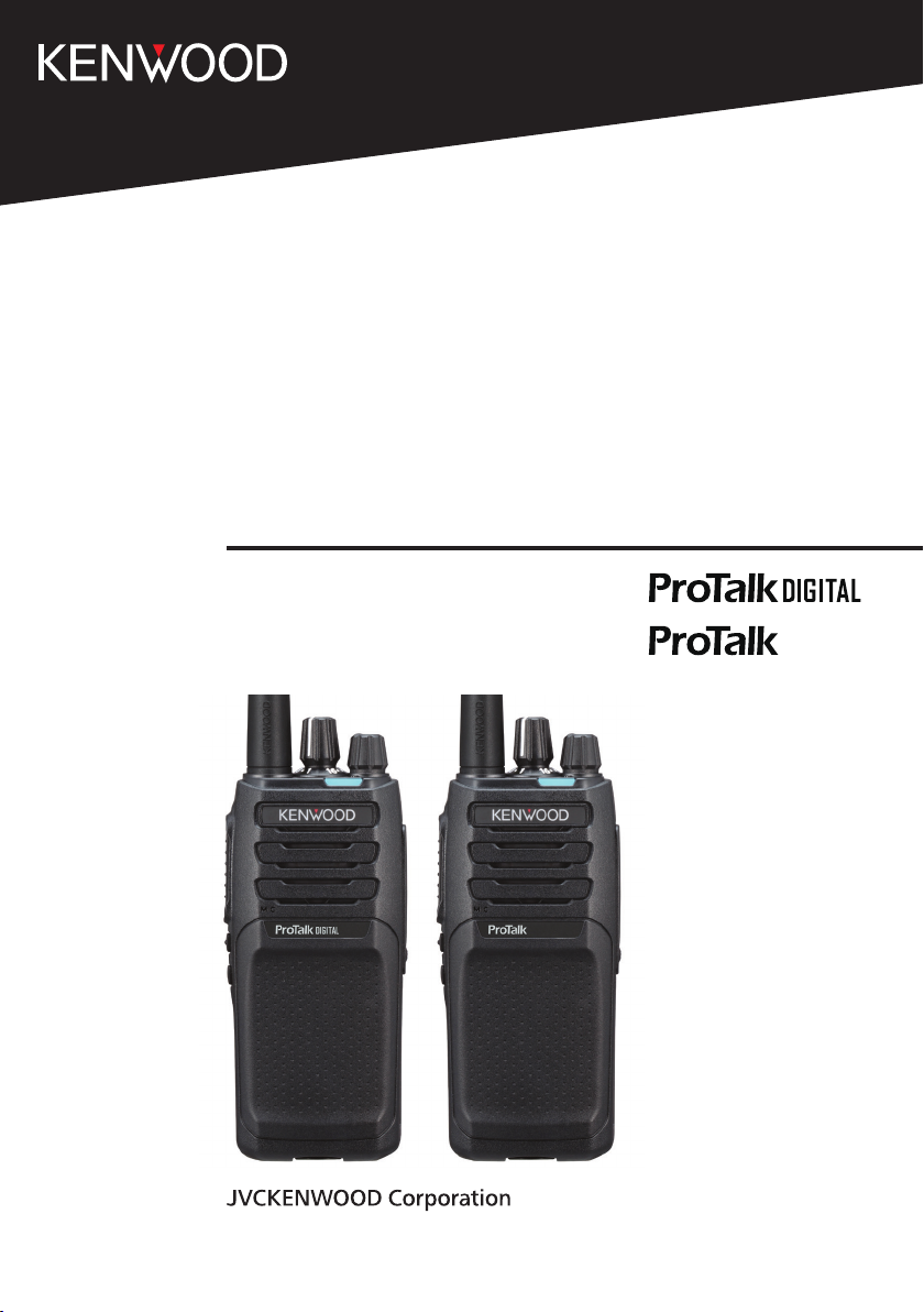
INSTALLING THE ANTENNA
Screw the antenna into the connector on the top of the
transceiver by holding the antenna at its base and turning it
clockwise until secure.
INSTALLING/ REMOVING THE BATTERY PACK
The battery pack is not charged at the factory; charge it before use.
CAUTION
◆Do not short the battery terminals or dispose of the battery by fire.
◆Never attempt to remove the casing from the battery pack.
1 Align the battery pack with the back of the
transceiver, then press the battery pack and
transceiver firmly together until the release latch on
the base of the transceiver locks.
Antenna
2 To remove the battery pack, lift the safety catch on
the base of the transceiver, then press the release
latch underneath the safety catch.
3 While pressing the release latch, pull the battery
pack away from the transceiver.
5
Page 6
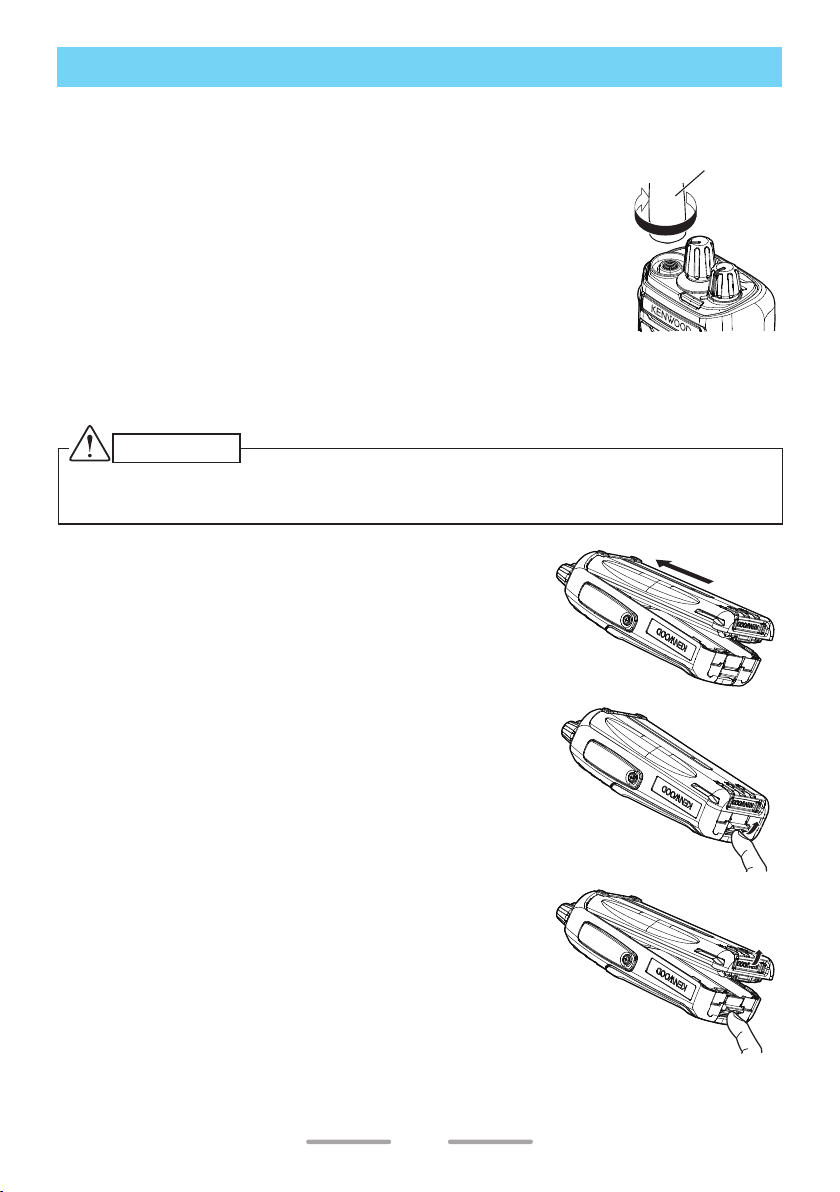
INSTALLING THE BELT CLIP
If necessary, attach the belt clip using the two
Belt clip
supplied M3 x 8 mm binding screws.
Note:
◆ If the belt clip is not installed, its mounting location
may get hot during continuous transmission or when
left sitting in a hot environment.
◆ Use the Phillips #2 screwdriver.
CAUTION
◆ Do not use glue which is designed to prevent screw loosening when installing the
belt clip, as it may cause damage to the transceiver. Acrylic ester, which is contained
in these glues, may crack the transceiver’s back panel.
M3 x 8 mm
screws
INSTALLING THE CAP OVER THE SPEAKER/ MICROPHONE JACKS
Note:
◆ For the speaker/ microphone jack, waterproof performance is guaranteed by securing
the supplied cap. Waterproof performance will not be guaranteed by connecting an
optional speaker/ microphone, etc.
◆ Use the Phillips #1 screwdriver.
1 If you are not using an optional speaker/
microphone or headset, install the cap over the
speaker/ microphone jacks.
2 Secure the cap in place using the attached screw.
6
Speaker/ microphone
jack cap
Screw
Page 7
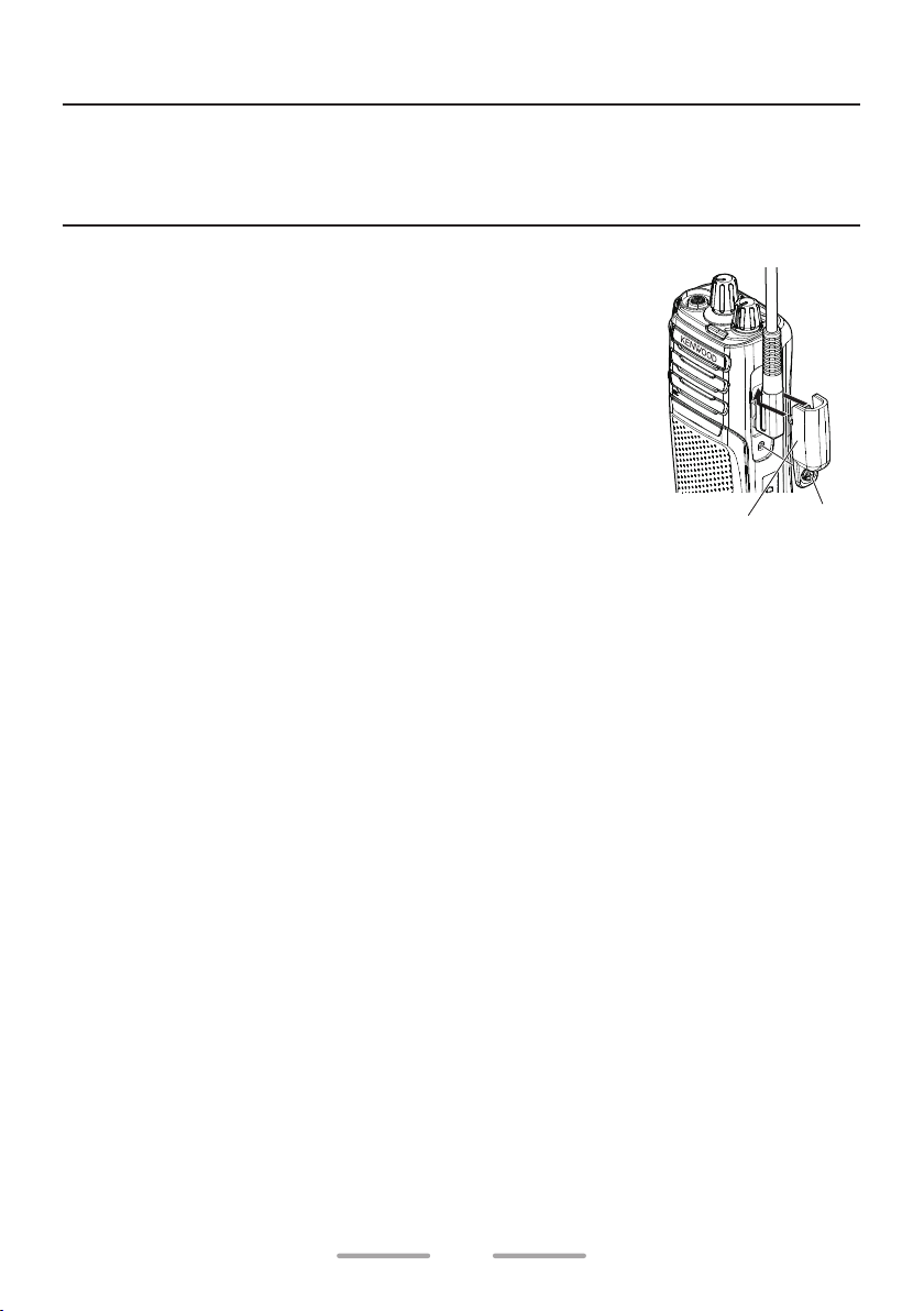
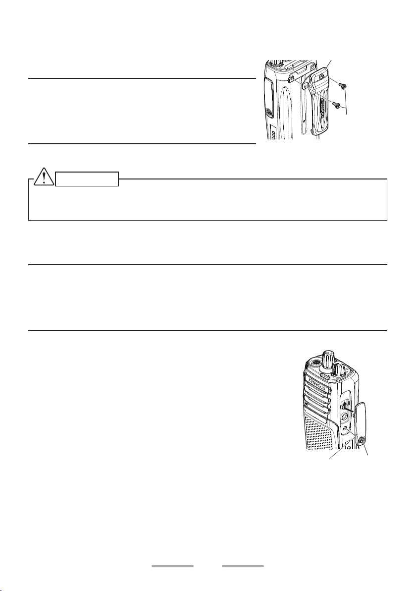
INSTALLING THE SPEAKER/ MICROPHONE OR HEADSET
Note:
◆ The transceiver is not fully water resistant when using a speaker/ microphone or
headset.
◆ Use the Phillips #1 screwdriver.
1 Insert the speaker/ microphone plugs into the
speaker/ microphone jacks of the transceiver.
2 Place the locking bracket over the speaker/
microphone plugs so that the locking tabs insert
into the transceiver grooves.
3 Secure the locking bracket in place using the
attached screw.
Speaker/ microphone
locking bracket
Screw
7
Page 8
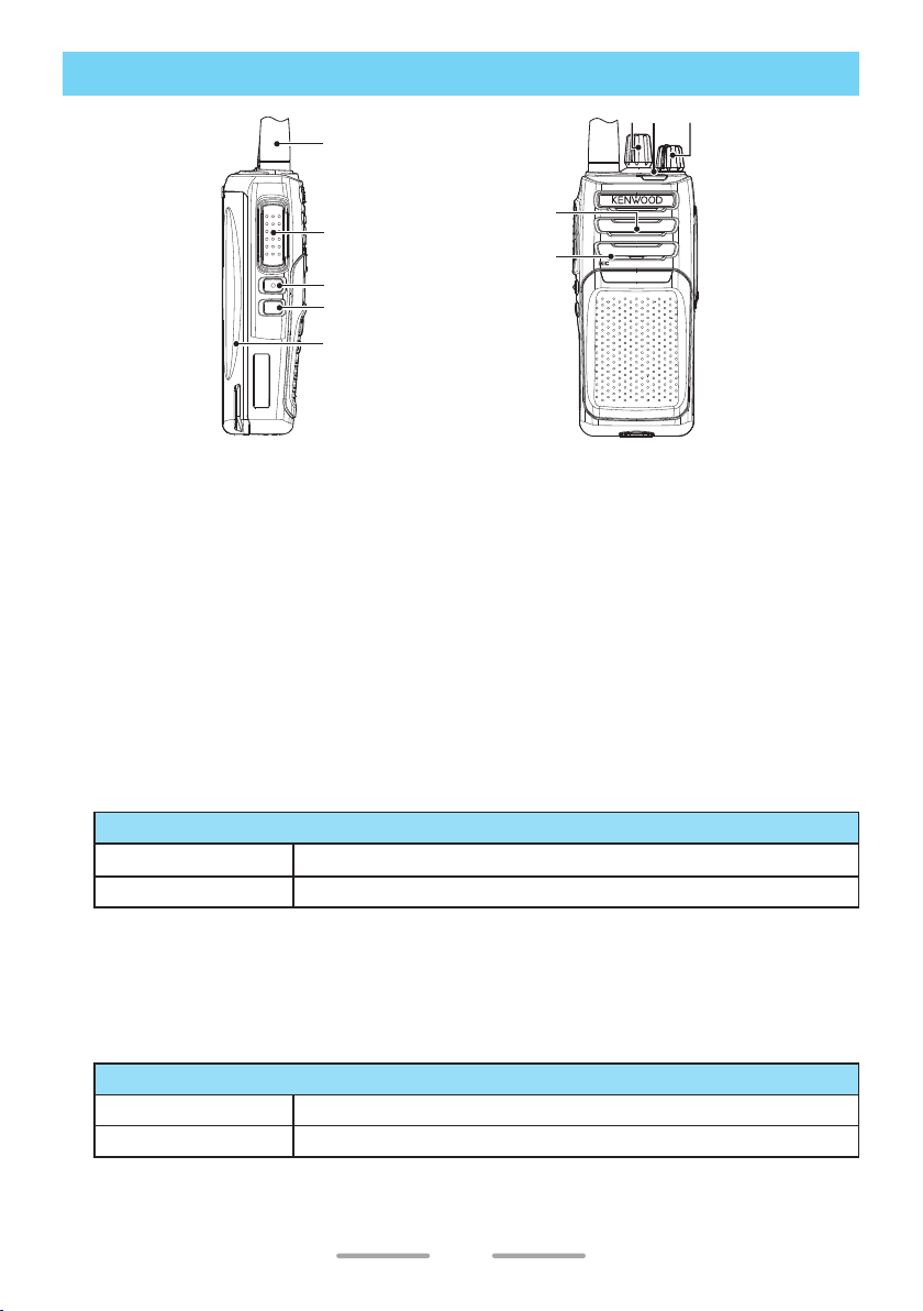
ORIENTATION
Antenna
ab c
d
e
f
Battery pack
Speaker
Microphone
a Selector
Rotate to change the operating channel.
b LED indicator
Refer to the “LED Indicator Status” {p. 10}.
c Power switch/ Volume control
Turn clockwise to switch the transceiver ON. To switch the transceiver OFF,
turn counterclockwise until a click sounds. Rotate to adjust the volume level.
d PTT (Push to Talk) switch
Press and hold, then speak into the microphone to transmit.
e Side 1 button
Press to activate its programmable function.
Default Function
Press None (No function)
Press and hold Zone Up
• For function descriptions and details on how to change the function
of the Side 1 button, refer to “BUTTON FUNCTION PROGRAMMING
MODE” {p. 35}.
f Side 2 button
Press to activate its programmable function.
Default Function
Press None (No function)
Press and hold Zone Down
• For function descriptions and details on how to change the function
of the Side 2 button, refer to “BUTTON FUNCTION PROGRAMMING
MODE” {p. 35}.
8
Page 9
BASIC OPERATION
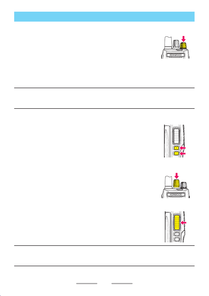
POWER ON
Turn the Power switch/ Volume control clockwise to switch the
transceiver power ON.
• Power-on tone will sound.
ADJUST THE VOLUME
Rotate the Power switch/ Volume control to adjust the volume.
• Clockwise increases the volume and counterclockwise decreases the volume.
Note:
◆ To adjust the volume using background noise as a reference in Analog mode, use the
[Monitor] or [Squelch O] function.
SELECT A ZONE
Press and hold the Side 1 button for 1 second to increase the
Zone number (Zone 1Zone 2Zone 3Zone 4Zone 1).
Press and hold the Side 2 button for 1 second to decrease the
Zone number (Zone 4Zone 3Zone 2Zone 1Zone 4).
• Side 1 and Side 2 buttons are the default settings.
SELECT A CHANNEL
Rotate the Selector to select your desired channel.
MAKE A CALL
Press and hold the PTT switch, then speak into the microphone
using your normal speaking voice.
• Hold the microphone approximately 3 to 4 cm (1.5 inches)
from your mouth.
Release the PTT switch to receive.
Note:
◆ When the battery pack voltage becomes too low, transmission will stop and an alert
tone will sound.
9
Page 10
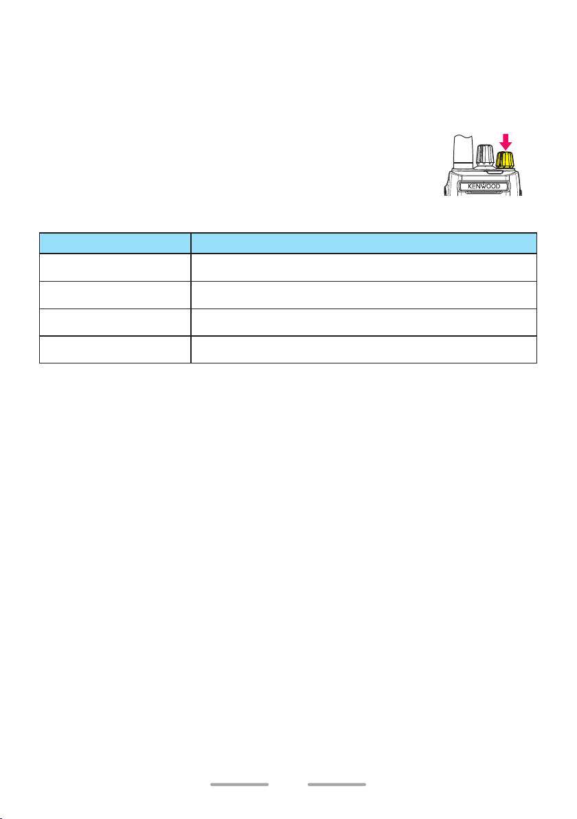
RECEIVE VOICE
The LED lights green.
When the other party transmits it, you hear the voice of the other party.
POWER OFF
After use, turn off the power. To switch the transceiver
power OFF, turn the Power switch/ Volume control fully
counterclockwise, until a click sounds.
LED Indicator Status
Indicator Color Meaning
Lights red Transmitting
Lights green Receiving a call.
Blinks red Battery power is low.
Blinks green Scanning
10
Page 11
SELF-PROGRAMMING MODE
This mode allows you to program the certain transceiver’s settings of zone and
channel.
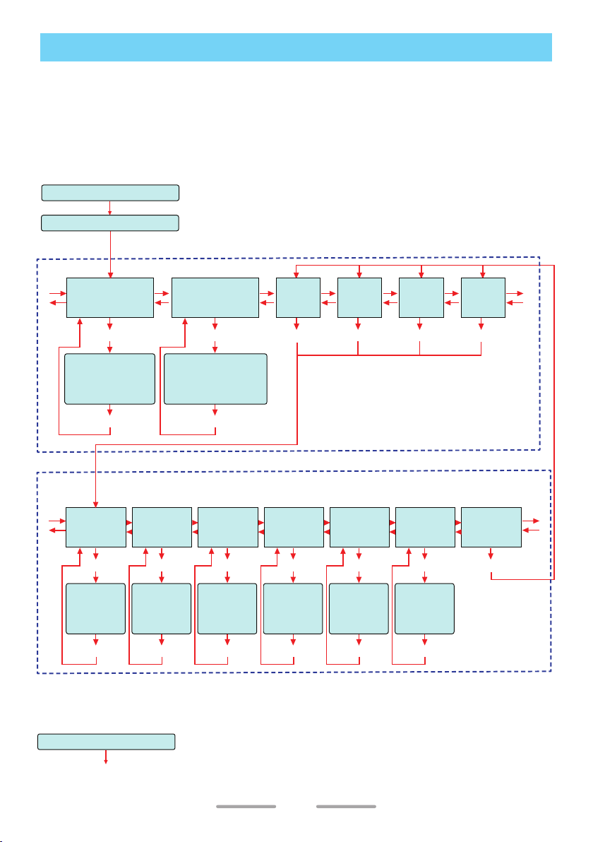
SELF-PROGRAMMING FLOW
Self-programming flow has two patterns depending on the model.
NX-P1200NV/ NX-P1300NU (NXDN/ Analog Transceiver)
[Side 1] + [PTT] + Power ON
Release [Side 1] + [PTT]
ID SETUP/ ZONE SELECTION
[Side 1]
A
B
[Side 2]
Select NXDN ID
[Selector] : Select digit
[Side 1] : Up
[Side 2] : Down
NXDN ID
Setup Mode
[PTT]
[PTT]
Reserved Group
Setup Mode
[PTT] [PTT]
Select Reserved Group ID
[Selector] : Select digit
[Side 1] : Up
[Side 2] : Down
[PTT]
Zone 1
Setup
Mode
Zone 2
Setup
Mode
[PTT]
CHANNEL SETUP
[Selector] : Change channel number.
TX
[PTT]
Transmit
Mode
Selection
[PTT]
*
2
Setup Mode
QT/DQT Table
QT/DQT
[PTT]
Selection
[PTT]
*
3
RAN
Setup Mode
[PTT]
RAN Table
Selection
[PTT]
*
[Side 1]
Frequency
C
Setup Mode
D
[Side 2]
[PTT]
Frequency
Table
Selection
[Side 1] / [Side 2]
[PTT]
*
1 : Channel type is selected from “NXDN” (Digital), “Analog” or “Mixed” (Dual).
*
2 : TX Setup Mode can be selected when Channel Type is “Mixed” (Dual).
*
3 : QT/DQT Setup Mode can be selected when Channel Type is “Analog” or “Mixed” (Dual).
*
4 : RAN Setup Mode can be selected when Channel Type is “NXDN” (Digital) or “Mixed” (Dual).
Channel Type
Setup Mode
Channel Type
[Side 1] / [Side 2] [Side 1] / [Side 2] [Side 1] / [Side 2] [Side 1] / [Side 2] [Side 1] / [Side 2]
1
Setup Mode
[PTT]
Selection
[PTT]
*
4
Zone 3
Setup
Mode
[PTT]
TX Power
Setup Mode
[PTT]
Transmit
Power
Selection
[PTT]
Zone 4
Setup
Mode
[PTT]
Confirmation
Setup Mode
[Side 1]
[Side 2]
[PTT]
Returns to the
currently set
zone number.
A
B
[Side 1]
C
D
[Side 2]
Power OFF and then ON
Return to normal operation
11
Page 12
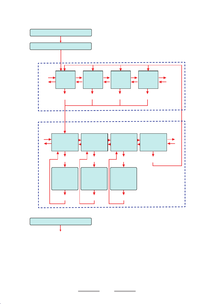
NX-P1200AV/ NX-P1202AV/ NX-P1300AU/ NX-P1302AU (Analog
Transceiver)
[Side 1] + [PTT] + Power ON
Release [Side 1] + [PTT]
ZONE SELECTION
[Side 1]
A
B
[Side 2]
[Side 1]
C
D
[Side 2]
Zone 1
Setup
Mode
[PTT]
Zone 2
Setup
Mode
[PTT]
CHANNEL SETUP
[Selector] : Change channel number.
Frequency
Setup Mode
[PTT]
Frequency
Table
Selection
[Side 1] / [Side 2]
[PTT]
QT/DQT
Setup Mode
[PTT]
QT/DQT Table
Selection
[Side 1] / [Side 2] [Side 1] / [Side 2]
[PTT]
Zone 3
Setup
Mode
[PTT]
TX Power
Setup Mode
[PTT]
Transmit
Power
Selection
[PTT]
Zone 4
Setup
Mode
[PTT]
Confirmation
Setup Mode
[PTT]
Returns to the
currently set
zone number.
[Side 1]
A
B
[Side 2]
[Side 1]
[Side 2]
C
D
Power OFF and then ON
Return to normal operation
12
Page 13

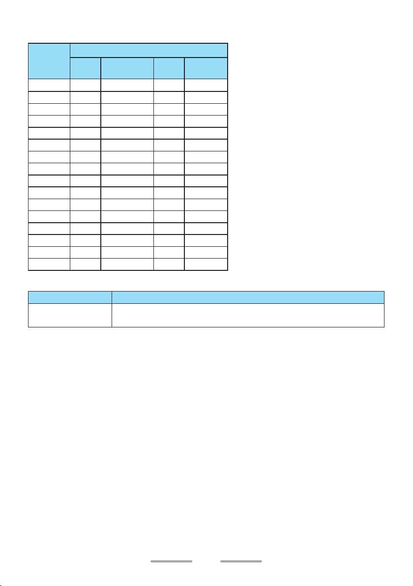
DEFAULT CHANNEL SETTINGS
This transceiver allows you to reprogram each of the channels with different
frequencies and QT tone/DQT code (Analog)/ RAN (NXDN (Digital)) settings.
NX-P1200NV
Channel
Number
1 1 151.6250 1 67.0 1 151.6250 1 1
2 1 151.6250 4 77.0 1 151.6250 2 2
3 1 151.6250 8 88.5 1 151.6250 3 3
4 1 151.6250 29 179.9 1 151.6250 4 4
5 1 151.6250 12 100.0 1 151.6250 5 5
6 2 151.9550 1 67.0 2 151.9550 1 1
7 2 151.9550 6 82.5 2 151.9550 2 2
8 2 151.9550 10 94.8 2 151.9550 3 3
9 2 151.9550 29 179.9 2 151.9550 4 4
10 2 151.9550 12 100.0 2 151.9550 5 5
11 20 154.4900 1 67.0 20 154.4900 1 1
12 21 154.5150 1 67.0 21 154.5150 1 1
13 10 151.5125 1 67.0 10 151.5125 1 1
14 12 151.6850 1 67.0 12 151.6850 1 1
15 5 151.7000 1 67.0 5 151.7000 1 1
16 6 151.7600 1 67.0 6 151.7600 1 1
Zone 1/ Zone 2 (Analog) Zone 3/ Zone 4 (Digital)
Table
No.
Frequency
(MHz)
Table
No.
QT (Hz)
Table
No.
Frequency
(MHz)
Table
No.
Compatible KENWOOD Model
Zone Number
Zone 1/ Zone 2
Zone 3/ Zone 4
NX-P1200AV (Zone 1 ~ 4)/ NX-P1202AV (Zone 2 ~ 4)/
NX-240 (Analog Mode)/ TK-2402V
NX-240 (Digital Mode)
Model Name
RAN
13
Page 14
NX-P1200AV (Analog Transceiver)
Channel
Number
10 2 151.9550 12 100.0
11 20 154.4900 1 67.0
12 21 154.5150 1 67.0
13 10 151.5125 1 67.0
14 12 151.6850 1 67.0
15 5 151.7000 1 67.0
16 6 151.7600 1 67.0
Table
No.
1 1 151.6250 1 67.0
2 1 151.6250 4 77.0
3 1 151.6250 8 88.5
4 1 151.6250 29 179.9
5 1 151.6250 12 100.0
6 2 151.9550 1 67.0
7 2 151.9550 6 82.5
8 2 151.9550 10 94.8
9 2 151.9550 29 179.9
Zone 1 ~ Zone 4
Frequency
(MHz)
Table
No.
Compatible KENWOOD Model
Zone Number
Zone 1 ~ Zone 4
NX-P1200NV (Zone 1/ 2)/ NX-P1202AV (Zone 2 ~ 4)/
NX-240 (Analog Mode)/ TK-2402V
QT (Hz)
Model Name
14
Page 15
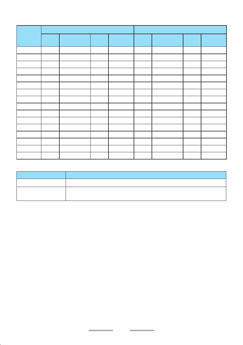
NX-P1202AV (Analog Transceiver)
Channel
Number
10 1 151.6250 8 88.5 2 151.9550 12 100.0
11 1 151.6250 29 179.9 20 154.4900 1 67.0
12 2 151.9550 6 82.5 21 154.5150 1 67.0
13 2 151.9550 10 94.8 10 151.5125 1 67.0
14 2 151.9550 29 179.9 12 151.6850 1 67.0
15 5 151.7000 1 67.0 5 151.7000 1 67.0
16 6 151.7600 1 67.0 6 151.7600 1 67.0
Table
No.
1 20 154.4900 1 67.0 1 151.6250 1 67.0
2 21 154.5150 1 67.0 1 151.6250 4 77.0
3 1 151.6250 1 67.0 1 151.6250 8 88.5
4 2 151.9550 1 67.0 1 151.6250 29 179.9
5 10 151.5125 1 67.0 1 151.6250 12 100.0
6 12 151.6850 1 67.0 2 151.9550 1 67.0
7 15 151.7750 1 67.0 2 151.9550 6 82.5
8 26 158.4000 1 67.0 2 151.9550 10 94.8
9 1 151.6250 4 77.0 2 151.9550 29 179.9
Zone 1 Zone 2 ~ Zone 4
Frequency
(MHz)
Table
No.
QT (Hz)
Table
No.
Frequency
(MHz)
Table
No.
Compatible KENWOOD Model
Zone Number
Zone 1
Zone 2 ~ Zone 4
TK-2400
NX-P1200NV (Zone 1/ 2) NX-P1200AV (Zone 1 ~ 4)/
NX-240 (Analog Mode)/ TK-2402V
Model Name
QT (Hz)
15
Page 16
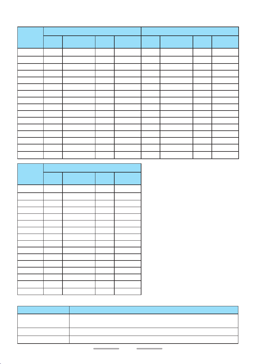
NX-P1300NU (NXDN/ Analog Transceiver)
Channel
Number
1 1 464.5000 1 67.0 1 464.5000 1 1
2 1 464.5000 4 77.0 1 464.5000 2 2
3 1 464.5000 8 88.5 1 464.5000 3 3
4 1 464.5000 29 179.9 1 464.5000 4 4
5 1 464.5000 12 100.0 1 464.5000 5 5
6 2 464.5500 1 67.0 2 464.5500 1 1
7 2 464.5500 6 82.5 2 464.5500 2 2
8 2 464.5500 10 94.8 2 464.5500 3 3
9 2 464.5500 29 179.9 2 464.5500 4 4
10 2 464.5500 12 100.0 2 464.5500 5 5
11 22 461.3625 3 74.4 22 461.3625 1 1
12 30 464.4875 5 79.7 30 464.4875 1 1
13 32 464.5375 7 85.4 32 464.5375 1 1
14 34 466.0375 9 91.5 34 466.0375 1 1
15 36 466.0875 11 97.4 36 466.0875 1 1
16 38 466.1375 13 103.5 38 466.1375 1 1
Channel
Number
1 2 464.5500 1 1
2 8 467.9250 1 1
3 9 461.0375 1 1
4 10 461.0625 1 1
5 11 461.0875 1 1
6 12 461.1125 1 1
7 13 461.1375 1 1
8 14 461.1625 1 1
9 1 464.5000 1 1
10 3 467.7625 1 1
11 4 467.8125 1 1
12 5 467.8500 1 1
13 6 467.8750 1 1
14 7 467.9000 1 1
15 15 461.1875 1 1
16 16 461.2125 1 1
Zone 1/ Zone 2 (Analog) Zone 3 (Digital)
Table
Table
No.
No.
Frequency
(MHz)
Zone 4 (Digital)
Frequency
(MHz)
Table
No.
Table
No.
QT (Hz)
RAN
Table
No.
Frequency
(MHz)
Table
No.
Compatible KENWOOD Model
Zone Number
Zone 1/ Zone 2
Zone 3
Zone 4
NX-P1300AU (Zone 1 ~ 4)/ NX-P1302AU (Zone 2 ~ 4)/
NX-340 (Analog Mode)/ TK-3402U
NX-340 (Digital Mode)
NX-P500 (Digital Mode)
Model Name
16
RAN
Page 17

NX-P1300AU (Analog Transceiver)
Channel
Number
10 2 464.5500 12 100.0
11 22 461.3625 3 74.4
12 30 464.4875 5 79.7
13 32 464.5375 7 85.4
14 34 466.0375 9 91.5
15 36 466.0875 11 97.4
16 38 466.1375 13 103.5
Table
No.
1 1 464.5000 1 67.0
2 1 464.5000 4 77.0
3 1 464.5000 8 88.5
4 1 464.5000 29 179.9
5 1 464.5000 12 100.0
6 2 464.5500 1 67.0
7 2 464.5500 6 82.5
8 2 464.5500 10 94.8
9 2 464.5500 29 179.9
Zone 1 ~ Zone 4
Frequency
(MHz)
Table
No.
Compatible KENWOOD Model
Zone Number
Zone 1 ~ Zone 4
NX-P1300NU (Zone 1/ 2)/ NX-P1302AU (Zone 2 ~ 4)/
NX-340 (Analog Mode)/ TK-3402U
QT (Hz)
Model Name
17
Page 18

NX-P1302AU (Analog Transceiver)
Channel
Number
10 3 467.7625 1 67.0 2 464.5500 12 100.0
11 4 467.8125 1 67.0 22 461.3625 3 74.4
12 5 467.8500 1 67.0 30 464.4875 5 79.7
13 6 467.8750 1 67.0 32 464.5375 7 85.4
14 7 467.9000 1 67.0 34 466.0375 9 91.5
15 15 461.1875 1 67.0 36 466.0875 11 97.4
16 16 461.2125 1 67.0 38 466.1375 13 103.5
Table
No.
1 2 464.5500 1 67.0 1 464.5000 1 67.0
2 8 467.9250 1 67.0 1 464.5000 4 77.0
3 9 461.0375 1 67.0 1 464.5000 8 88.5
4 10 461.0625 1 67.0 1 464.5000 29 179.9
5 11 461.0875 1 67.0 1 464.5000 12 100.0
6 12 461.1125 1 67.0 2 464.5500 1 67.0
7 13 461.1375 1 67.0 2 464.5500 6 82.5
8 14 461.1625 1 67.0 2 464.5500 10 94.8
9 1 464.5000 1 67.0 2 464.5500 29 179.9
Zone 1 Zone 2 ~ Zone 4
Frequency
(MHz)
Table
No.
QT (Hz)
Table
No.
Frequency
(MHz)
Table
No.
Compatible KENWOOD Model
Zone Number
Zone 1
Zone 2 ~ Zone 4
TK-3400/ NX-P500 (Analog Mode)
NX-P1300NU (Zone 1/ 2)/ NX-P1300AU (Zone 1 ~ 4)/
NX-340 (Analog Mode)/ TK-3402U
Model Name
QT (Hz)
18
Page 19

ID SETUP
NXDN ID Setup (Digital)
NXDN ID Setup allows you to configure an identification code. NXDN ID (Own unit
ID) can be used to identify the transceiver in an NXDN System.
You can set the NXDN ID from 00001 to 65519. The default NXDN ID is “00001”.
To set the NXDN ID
1 With the transceiver power OFF, press and hold the Side 1 button and PTT
switch while turning the transceiver power ON.
• Continue to hold the Side 1 button and PTT switch until the LED lights
yellow and the transceiver announces “Self”.
2 Release the Side 1 button and PTT switch to enter the ID SETUP/ ZONE
SELECTION.
• The transceiver announces “NXDN ID”.
3 Press the PTT switch to enter the NXDN ID Setup Mode.
4 Turn the Selector to set the pointer to the desired digit (1 ~ 5).
• A voice announcement will inform selected number.
• If you select more than 5 digit, error beep will sound.
5 Press the Side 1 to increase the number, press the Side 2 to decrease the
number (0 ~ 9).
• A voice announcement will inform selected number.
• Repeat steps 4 to 5 to select the number of each digit.
• For example, when you set the NXDN ID as “12345”, you should operate
the Selector, Side 1 and Side 2 buttons according to the following table.
Selector position
Selected number
5
1
4 3 2 1
2 3 4 5
6 Press the PTT switch to save the settings and return to the ID SETUP/ ZONE
SELECTION.
• A voice announcement will inform you of the currently selected NXDN ID
number. For example, when “12345” is selected, voice announcement: “ID,
One, Two, Three, Four, Five”.
• Turn the transceiver power OFF and then ON return to normal operation
with new settings.
Note:
◆ If no action is performed for 20 seconds, the transceiver will automatically return to
normal operation without changing any settings.
19
Page 20

Reserved Group Setup (Digital)
Reserved Group Setup allows you to configure the Reserved Group ID.
Reserved Group ID is the ID that is the destination of Group Call communication
in the channel where Selcall on PTT > Call Type (NXDN) is set to “Reserved
Group”.
You can set the Reserved Group ID from “00001” to “65519”. The default ID is
“00100”.
• Only on the channels in Zone 4 of NX-P1300NU, Reserved Group function
(making a Group Call with the Reserved Group ID) can be used by default
settings.
• If you use Reserved Group function on NX-P1200NV or the other zones of NXP1300NU, the settings by your dealer are required.
• Reserved Group ID: 00100 is compatible with NX-P500.
• If other parties use the same frequency, changing the Reserved Group ID
and making a Group Call with a Group ID other than “00100” can prevent
unnecessary reception.
A group call is initiated to the transceiver of the same Reserved Group ID if the
PTT switch is pressed.
Group Call receiving transceivers
Group Call
Transceiver B
Transceiver A
Reserved Group
ID : 00100
Transceiver D
Reserved Group
ID : 00100
Reserved Group
ID : 00100
Transceiver C
Reserved Group
ID : 00100
To set the Reserved Group ID
1 With the transceiver power OFF, press and hold the Side 1 button and PTT
switch while turning the transceiver power ON.
• Continue to hold the Side 1 button and PTT switch until the LED lights
yellow and the transceiver announces “Self”.
2 Release the Side 1 button and PTT switch to enter the ID SETUP/ ZONE
SELECTION.
20
Page 21

3 Press the Side 1 or Side 2 button to select the Reserved Group Setup Mode.
• The transceiver announces “Group ID”.
4 Press the PTT switch to enter the Reserved Group Setup Mode.
5 Turn the Selector to set the pointer to the desired digit (1 ~ 5).
• A voice announcement will inform selected number.
• If you select more than 5 digit, error beep will sound.
6 Press the Side 1 to increase the number, press the Side 2 to decrease the
number (0 ~ 9).
• A voice announcement will inform selected number.
• Repeat steps 5 to 6 to select the number of each digit.
• For example, when you set the Reserved Group ID as “00250”, you should
operate the Selector, Side 1 and Side 2 buttons according to the following
table.
Selector position
Selected number
5
0
4 3 2 1
0 2 5 0
7 Press the PTT switch to save the settings and return to the ID SETUP/ ZONE
SELECTION.
• A voice announcement will inform you of the currently selected Reserved
Group ID number. For example, when “00250” is selected, voice
announcement: “ID, Zero, Zero, Two, Five, Zero”.
• Turn the transceiver power OFF and then ON return to normal operation
with new settings.
Note:
◆ If no action is performed for 20 seconds, the transceiver will automatically return to
normal operation without changing any settings.
21
Page 22

ZONE SELECTION
1 With the transceiver power OFF, press and hold the Side 1 button and PTT
switch while turning the transceiver power ON.
• Continue to hold the Side 1 button and PTT switch until the LED lights
yellow and the transceiver announces “Self”.
2 Release the Side 1 button and PTT switch to enter the ID SETUP/ ZONE
SELECTION.
3 Press the Side 1 or Side 2 button to select a zone number.
• A voice announcement will inform you of the currently selected zone
number.
4 Press the PTT switch to decide current selected zone and enter the CHANNEL
SETUP {p. 23}.
• A voice announcement will inform you of the currently selected zone
number and channel number “Zone X” (X = 1 to 4 for zone number),
“Channel Y” (Y = 1 to 16 for channel number).
Note:
◆ If no action is performed for 20 seconds, the transceiver will automatically return to
normal operation without changing any settings.
22
Page 23

CHANNEL SETUP
Frequency Setup
To set the Frequency
1 During CHANNEL SETUP, rotate the Selector to select a channel number.
• The transceiver announces the zone number and channel number.
2 Press the Side 1 or Side 2 button to select the Frequency Setup Mode.
• The transceiver announces “Channel”.
3 Press the PTT switch to enter the Frequency Table Selection.
• The transceiver will announce the current frequency table number.
4 Press the Side 1 or Side 2 button to increment/ decrement the frequency table
number, to select the new channel frequency.
• A voice announcement: “Table X” (X = 1 to 27 for VHF, X = 1 to 99 for UHF).
• A voice announcement will inform you of the currently selected frequency
table number.
• Table numbers and their corresponding operating frequencies are provided
in the table {VHF: p. 24} {UHF: p. 25}.
• Press and hold the Side 1 or Side 2 button to increment/ decrement the
frequency table number by 5 at a time.
5 Press the PTT switch to temporary save the selected frequency table number.
• Beep B (2 beeps) will sound.
• Repeat steps 1 to 5 to set up another channel.
6 Press the Side 1 or Side 2 button to select the Confirmation Setup Mode.
• The transceiver announces “Confirm”.
7 Press the PTT switch to save the settings and return to the ID SETUP/ ZONE
SELECTION.
• Beep B (2 beeps) will sound.
• Turn the transceiver power OFF and then ON return to normal operation
with new settings.
Note:
◆ If no action is performed for 20 seconds, the transceiver will automatically return to
normal operation without changing any settings.
23
Page 24

VHF Frequency Table
Table Number Frequency (MHz)
1 151.625000
2 151.955000
3 152.885000
4 152.915000
5 151.700000
6 151.760000
7 152.945000
8 151.835000
9 151.805000
10 151.512500
11 151.655000
12 151.685000
13 151.715000
14 151.745000
15 151.775000
16 151.865000
17 151.895000
18 151.925000
19 152.900000
20 154.490000
21 154.515000
22 154.527500
23 154.540000
24 153.005000
25 154.547500
26 158.400000
27 158.407500
24
Page 25

UHF Frequency Table
Table
Number
1 464.500000 34 466.037500 67 451.287500
2 464.550000 35 466.062500 68 451.337500
3 467.762500 36 466.087500 69 451.437500
4 467.812500 37 466.112500 70 451.537500
5 467.850000 38 466.137500 71 451.637500
6 467.875000 39 466.162500 72 452.312500
7 467.900000 40 466.187500 73 452.537500
8 467.925000 41 466.212500 74 452.412500
9 461.037500 42 466.237500 75 452.512500
10 461.062500 43 466.262500 76 452.762500
11 461.087500 44 466.287500 77 452.862500
12 461.112500 45 466.312500 78 456.187500
13 461.137500 46 466.337500 79 456.237500
14 461.162500 47 466.362500 80 456.287500
15 461.187500 48 467.787500 81 468.212500
16 461.212500 49 467.837500 82 468.262500
17 461.237500 50 467.862500 83 468.312500
18 461.262500 51 467.887500 84 468.362500
19 461.287500 52 467.912500 85 468.412500
20 461.312500 53 469.487500 86 468.462500
21 461.337500 54 469.512500 87 468.512500
22 461.362500 55 469.537500 88 468.562500
23 462.762500 56 469.562500 89 468.612500
24 462.787500 57 462.187500 90 468.662500
25 462.812500 58 462.462500 91 456.337500
26 462.837500 59 462.487500 92 456.437500
27 462.862500 60 462.512500 93 456.537500
28 462.887500 61 467.187500 94 456.637500
29 462.912500 62 467.462500 95 457.312500
30 464.487500 63 467.487500 96 457.412500
31 464.512500 64 467.512500 97 457.512500
32 464.537500 65 451.187500 98 457.762500
33 464.562500 66 451.237500 99 457.862500
Frequency
(MHz)
Table
Number
Frequency
(MHz)
Table
Number
Frequency
(MHz)
25
Page 26

Channel Type Setup
Set the Channel Type of the selected Zone-Channel to “Analog”, “NXDN” (Digital),
or “Mixed” (Dual). The following is the transceiver behavior for transmission and
reception on a channel with “Mixed” (Dual) configured in Channel Type:
Transmission: The transceiver transmits in the mode (Analog or NXDN)
configured in the TX Setup Mode
Reception: Mixed mode can be used to wait for a call in both Analog (QT tone
and DQT code) and Digital (RAN) modes.
To set the Channel Type
1 During CHANNEL SETUP, rotate the Selector to select a channel number.
• The transceiver announces the zone number and channel number.
2 Press the Side 1 or Side 2 button to select the Channel Type Setup Mode.
• The transceiver announces “Channel Type”.
• If the Frequency of the currently selected channel is set to “Off”, the
Channel Type Setup Mode cannot be selected.
3 Press the PTT switch to enter the Channel Type Selection.
4 Press the Side 1 or Side 2 button to select the Channel Type.
Channel Type Voice Announcement Description
Analog Channel Type Analog
NXDN Channel Type Digital
Mixed Channel Type Dual
{p. 27}.
Operate in Analog mode.
Operate in Digital mode.
Operate in Analog / Digital Mixed mode.
5 Press the PTT switch to temporary save the selected Channel Type.
• Beep B (2 beeps) will sound.
• Repeat steps 1 to 5 to set up another channel.
6 Press the Side 1 or Side 2 button to select the Confirmation Setup Mode.
• The transceiver announces “Confirm”.
7 Press the PTT switch to save the settings and return to the ID SETUP/ ZONE
SELECTION.
• Beep B (2 beeps) will sound.
• Turn the transceiver power OFF and then ON return to normal operation
with new settings.
Note:
◆ If no action is performed for 20 seconds, the transceiver will automatically return to
normal operation without changing any settings.
26
Page 27

TX Setup
When Channel Type is “Mixed” (Dual), set to “Analog” or “NXDN” (Digital) for
Transmit Mode.
To set the Transmit Mode
1 During CHANNEL SETUP, rotate the Selector to select a channel number.
• The transceiver announces the zone number and channel number.
2 Press the Side 1 or Side 2 button to select the TX Setup Mode.
• The transceiver announces “TX Mode”.
• If the Frequency of the currently selected channel is set to “Off”, the TX
Setup Mode cannot be selected.
• If the Channel Type is set to “Analog” or “NXDN” (Digital), the TX Setup
Mode cannot be selected.
3 Press the PTT switch to enter the Transmit Mode Selection.
4 Press the Side 1 or Side 2 button to select the Transmit Mode.
Transmit Mode Voice Announcement Description
Analog TX Mode Analog
NXDN TX Mode Digital
5 Press the PTT switch to temporary save the selected Transmit Mode.
• Beep B (2 beeps) will sound.
• Repeat steps 1 to 5 to set up another channel.
6 Press the Side 1 or Side 2 button to select the Confirmation Setup Mode.
• The transceiver announces “Confirm”.
7 Press the PTT switch to save the settings and return to the ID SETUP/ ZONE
SELECTION.
• Beep B (2 beeps) will sound.
• Turn the transceiver power OFF and then ON return to normal operation
with new settings.
Transmitting in Analog.
Transmitting in Digital.
Note:
◆ If no action is performed for 20 seconds, the transceiver will automatically return to
normal operation without changing any settings.
27
Page 28

Operation
• If Transmit Mode is set to “Analog”, the transceiver will respond to a call in
Analog format.
• If Transmit Mode is set to “NXDN” (Digital), the transceiver will respond to a call
in NXDN format.
• In a mixed channel, if the transceiver receives matched Signaling (QT/DQT/
RAN), the transceiver will be able to transmit in the same mode as that of
the received signal before the Signaling Reset Timer (10 seconds) elapses,
regardless of the Transmit Mode settings.
- This operation of transmitting in the same mode as that of the received
signal is called Talkback.
- The operation when transmission is done on a mixed channel while
receiving a signal is as follows.
TX Operation when Signaling
Transmit
Mode
Analog Analog
Analog Digital
NXDN Analog
NXDN Digital X O X O
Received
Signal
Transmission
is mismatched
Analog
O X O X
O X X O
X O O X
NXDN
Transmission
TX Operation when Signaling
Transmission
is matched
Analog
Transmission
O: Can transmit
X: Cannot transmit
NXDN
28
Page 29

QT/DQT Setup (Analog)
Quiet Talk (QT) and Digital Quiet Talk (DQT) are functions that reject undesired
signals on your channel. You will hear a call only when you receive a signal that
contains a matching QT tone or DQT code. If a call containing a different tone or
code is received, squelch will not open and you will not hear the call. Likewise,
when transmitting using QT tone or DQT code, the receiving station must have a
matching tone or code to hear your call.
Be aware that other parties can still hear your calls if they set up their transceiver
with the same tone or code.
To set the QT/DQT
1 During CHANNEL SETUP, rotate the Selector to select a channel number.
• The transceiver announces the zone number and channel number.
2 Press the Side 1 or Side 2 button to select the QT/DQT Setup Mode.
• The transceiver announces “QT/DQT”.
• If the Frequency of the currently selected channel is set to “Off”, the QT/
DQT Setup Mode cannot be selected.
• If the Channel Type is set to “NXDN” (Digital), the QT/DQT Setup Mode
cannot be selected.
3 Press the PTT switch to enter the QT/DQT Table Selection.
• The transceiver announces the current QT/DQT table number.
4 Press the Side 1 or Side 2 button to increment/ decrement the QT/DQT table
number. (Table 0 (“QT DQT 0”) ↔ QT Table 1 (“QT 1”) ↔ QT Table 2 ↔ …
QT Table 45 ↔ DQT Table 1 ("DQT 1") ↔ DQT Table 2 ↔ … ↔ DQT Table 174
Table 0 (“QT DQT 0”)).
↔
• A voice announcement: “QT DQT 0”/ “QT X” (X = 1 to 45)/ “DQT X” (X = 1 to
174).
• A voice announcement will inform you of the currently selected QT/DQT
table number.
• QT/DQT table numbers and their corresponding tones/ codes are provided
in the table {QT: p. 30} {DQT: p. 31}.
• When table number set to “0” (“QT DQT 0”), QT/DQT signaling is off.
• Press and hold the Side 1 or Side 2 button to increment/ decrement the
QT/DQT table number by 5 at a time.
5 Press the PTT switch to temporary save the selected QT/DQT.
• Beep B (2 beeps) will sound.
• Repeat steps 1 to 5 to set up another channel.
6 Press the Side 1 or Side 2 button to select the Confirmation Setup Mode.
• The transceiver announces “Confirm”.
↔
29
Page 30

7 Press the PTT switch to save the settings and return to the ID SETUP/ ZONE
SELECTION.
• Beep B (2 beeps) will sound.
• Turn the transceiver power OFF and then ON
new settings
.
return to normal operation with
Note:
◆ If no action is performed for 20 seconds, the transceiver will automatically return to
normal operation without changing any settings.
Table Number QT/DQT
0 O
QT Table
Table
Number
1 67.0 21 136.5 41 67.0
2 71.9 22 141.3 42 67.0
3 74.4 23 146.2 43 67.0
4 77.0 24 151.4 44 67.0
5 79.7 25 156.7 45 67.0
6 82.5 26 162.2
7 85.4 27 167.9
8 88.5 28 173.8
9 91.5 29 179.9
10 94.8 30 186.2
11 97.4 31 192.8
12 100.0 32 203.5
13 103.5 33 210.7
14 107.2 34 218.1
15 110.9 35 225.7
16 114.8 36 233.6
17 118.8 37 241.8
18 123.0 38 250.3
19 127.3 39 69.3
20 131.8 40 67.0
QT Frequency
(Hz)
Table
Number
QT Frequency
(Hz)
Table
Number
Note:
◆ Table Number 40 to 45 can be changed by your dealer.
QT Frequency
(Hz)
30
Page 31

DQT Table
Table
Number
10 D065N 45 D343N 80 D732N 115 D223I 150 D565I
11 D071N 46 D346N 81 D734N 116 D226I 151 D606I
12 D072N 47 D351N 82 D743N 117 D243I 152 D612I
13 D073N 48 D364N 83 D754N 118 D244I 153 D624I
14 D074N 49 D365N 84 D645N 119 D245I 154 D627I
15 D114N 50 D371N 85 D023I 120 D251I 155 D631I
16 D115N 51 D411N 86 D025I 121 D261I 156 D632I
17 D116N 52 D412N 87 D026I 122 D263I 157 D654I
18 D125N 53 D413N 88 D031I 123 D265I 158 D662I
19 D131N 54 D423N 89 D032I 124 D271I 159 D664I
20 D132N 55 D431N 90 D043I 125 D306I 160 D703I
21 D134N 56 D432N 91 D047I 126 D311I 161 D712I
22 D143N 57 D445N 92 D051I 127 D315I 162 D723I
23 D152N 58 D464N 93 D054I 128 D331I 163 D731I
24 D155N 59 D465N 94 D065I 129 D343I 164 D732I
25 D156N 60 D466N 95 D071I 130 D346I 165 D734I
26 D162N 61 D503N 96 D072I 131 D351I 166 D743I
27 D165N 62 D506N 97 D073I 132 D364I 167 D754I
28 D172N 63 D516N 98 D074I 133 D365I 168 D645I
29 D174N 64 D532N 99 D114I 134 D371I 169 D023N
30 D205N 65 D546N 100 D115I 135 D411I 170 D023N
31 D223N 66 D565N 101 D116I 136 D412I 171 D023N
32 D226N 67 D606N 102 D125I 137 D413I 172 D023N
33 D243N 68 D612N 103 D131I 138 D423I 173 D023N
34 D244N 69 D624N 104 D132I 139 D431I 174 D023N
35 D245N 70 D627N 105 D134I 140 D432I
DQT
Code
1 D023N 36 D251N 71 D631N 106 D143I 141 D445I
2 D025N 37 D261N 72 D632N 107 D152I 142 D464I
3 D026N 38 D263N 73 D654N 108 D155I 143 D465I
4 D031N 39 D265N 74 D662N 109 D156I 144 D466I
5 D032N 40 D271N 75 D664N 110 D162I 145 D503I
6 D043N 41 D306N 76 D703N 111 D165I 146 D506I
7 D047N 42 D311N 77 D712N 112 D172I 147 D516I
8 D051N 43 D315N 78 D723N 113 D174I 148 D532I
9 D054N 44 D331N 79 D731N 114 D205I 149 D546I
Table
Number
DQT
Code
Table
Number
DQT
Code
Table
Number
DQT
Code
Table
Number
DQT
Code
Note:
◆ Table Number 169 to 174 can be changed by your dealer.
31
Page 32

RAN Setup (Digital)
RAN (Radio Access Number) is a signaling system designed for NXDN System.
When a channel is setup with a RAN, squelch will only open when a call
containing a matching RAN is received. If a call containing a different RAN is
made on the same channel are using, you will not hear the call. This allows you to
ignore (not hear) calls from other parties who are using the same channel.
To set the RAN
1 During CHANNEL SETUP, rotate the Selector to select a channel number.
• The transceiver announces the zone number and channel number.
2 Press the Side 1 or Side 2 button to select the RAN Setup Mode.
• The transceiver announces “RAN”.
3 Press the PTT switch to enter the RAN Table Selection.
• The transceiver will announce the current RAN table number.
4 Press the Side 1 or Side 2 to increment/ decrement the RAN table number.
• A voice announcement: “RAN X” (X = 0 to 63).
• A voice announcement will inform you of the currently selected RAN table
number.
• When RAN table number set to “0” (“RAN 0”), RAN signaling is off.
• Press and hold the Side 1 or Side 2 button to increment/ decrement the
RAN table number by 5 at a time.
5 Press the PTT switch to temporary save the selected RAN table number.
• Beep B (2 beeps) will sound.
• Repeat steps 1 to 5 to set up another channel.
6 Press the Side 1 or Side 2 button to select the Confirmation Setup Mode.
• The transceiver announces “Confirm”.
7 Press the PTT switch to save the settings and return to the ID SETUP/ ZONE
SELECTION
• Beep B (2 beeps) will sound.
• Turn the transceiver power OFF and then ON return to normal operation
with new settings.
Note:
◆ If no action is performed for 20 seconds, the transceiver will automatically return to
normal operation without changing any settings.
32
Page 33

TX Power Setup
To set the Transmit Power
1 During CHANNEL SETUP, rotate the Selector to select a channel number.
• The transceiver announces the zone number and channel number.
2 Press the Side 1 or Side 2 button to select the TX Power Setup Mode.
• The transceiver announces “TX Power”.
• If the Frequency of the currently selected channel is set to “Off”, the TX
Power Setup Mode cannot be selected.
3 Press the PTT switch to enter the Transmit Power Selection.
4 Press the Side 1 or Side 2 button to select the Transmit Power.
NX-P1200NV/ NX-P1200AV/ NX-P1300NU/ NX-P1300AU
Transmit Power Voice Announcement Description
High TX Power High 5 W
Medium
Low
NX-P1202AV/ NX-P1302AU
Transmit Power Voice Announcement Description
High TX Power High 2 W
Low TX Power Low
TX Power Medium 4 W
TX Power Low 1 W
1 W
5 Press the PTT switch to temporary save the selected Transmit Power.
• Beep B (2 beeps) will sound.
• Repeat steps 1 to 5 to set up another channel.
6 Press the Side 1 or Side 2 button to select the Confirmation Setup Mode.
• The transceiver announces “Confirm”.
7 Press the PTT switch to save the settings and return to the ID SETUP/ ZONE
SELECTION
• Beep B (2 beeps) will sound.
• Turn the transceiver power OFF and then ON return to normal operation
with new settings.
Note:
◆ If no action is performed for 20 seconds, the transceiver will automatically return to
normal operation without changing any settings.
33
Page 34

CHANNEL CONFIRMATION MODE
To confirm your channel settings:
1 With the transceiver power OFF, press and hold the PTT switch while turning
the transceiver power ON.
• Continue to hold the PTT switch until the LED lights yellow and the
transceiver announces “Confirm”.
2 Release the PTT switch.
• The transceiver announces the Zone number of the selected channel.
3 Rotate the Selector to desired channel.
The transceiver announces the information of the current channel.
NX-P1200NV/ NX-P1300NU
Channel Type:
Zone number, Channel number, Channel type, Frequency table number, QT/
DQT table number, Transmit power, Scrambler status, and VOX status.
(Example: “Zone 1, Channel 1, Analog, Table 10, DQT 15, High Power,
Scrambler (when active), VOX (when active)”)
Channel Type:
Zone number, Channel number, Channel type, Frequency table number, RAN
table number, Transmit power, Encryption status, and VOX status.
(Example: “Zone 1, Channel 1, Digital, Table 10, RAN 55, High Power,
Encryption (when active), VOX (when active)”)
Channel Type: Mixed
Zone number, Channel number, Channel type, Transmit mode, Frequency
table number, QT/DQT table number, RAN table number, Transmit power,
Scrambler status, Encryption status, and VOX status.
(Example: “Zone 1, Channel 1, Dual, Analog, Table 10, DQT 15, RAN 55,
High Power, Scrambler (when active), Encryption (when active), VOX (when
active)”)
NX-P1200AV/ NX-P1300AU/ NX-P1202AV/ NX-P1302AU
Zone number, Channel number, Frequency table number, QT/DQT table
number, Transmit power, Scrambler status, and VOX status.
• Press the PTT switch to repeat the voice announcement of the channel
information of the current channel.
• Press the Side 1 or Side 2 button to increment or decrement the zone
number with voice announcement of zone number.
• If the QT/DQT or RAN of the currently selected channel is not set, the
transceiver will not announce the QT/DQT or RAN table number.
Analog
NXDN
Note:
◆ If no action is performed for 20 seconds, the transceiver will automatically return to
normal operation without changing any settings.
34
Page 35

BUTTON FUNCTION PROGRAMMING MODE
This transceiver allows you to reprogram the Side 1 and Side 2 buttons with any
of the functions listed in the table below. Explanations on the use of each function
are provided under “PROGRAMMABLE FUNCTIONS” {p. 37}.
FUNCTIONS LIST
Table
Number
0 None – –
1 – Button Lock 1 X
2 Calling Alert – – O
3 External Speaker – – X
4 Home Channel Home Channel Select 3 X
5 Individual Reply – – X
6 Low Transmit Power – – X
7 Monitor – – O
8 Monitor Momentary – – O
9 Scan Scan Temporary Delete 3 X
10 Scrambler/ Encryption – – X
11 Speaker Attenuation – – X
12 Squelch O – – O
13 Squelch O Momentary – – O
14 – Super Lock 4 –
15 – Zone Down 1 X
16 – Zone Up 1 X
17 – Channel Down 1 X
18 – Channel Up 1 X
Press Press and hold
Hold
Delay
Time (sec)
Operation
during Super
Lock
O: Can operate
X: Cannot operate
Note:
◆ No. 15 [Zone Down] and No. 16 [Zone Up] cannot be selected when [Zone Select]
function {p. 43} is set to the Selector by your dealer.
◆ No. 17 [Channel Down] and No. 18 [Channel Up] cannot be selected when [Channel
Select] function is set to the Selector (including the default settings).
◆ The “Press and hold” function is assigned automatically.
35
Page 36

To set the functions of the Side 1 and Side 2 buttons
1 With the transceiver power OFF, press and hold the Side 1 and Side 2 buttons
while turning the transceiver power ON.
• Continue to hold the Side 1 and Side 2 buttons until the LED lights yellow
and the transceiver announces “Setup”.
2 Release the button.
3 Press and hold the button to be reprogrammed (either the Side 1 or Side 2
button).
• The transceiver will announce “Table 0”.
- The selection table number starts from “Table 0”, not the current table
number.
4 Release the button.
5 Press the Side 1 or Side 2 button to increment/ decrement the table number, to
select the new button function.
• Table numbers and their corresponding functions are provided in the table
{p. 35}.
• A voice announcement will inform you of the currently selected table
number.
6 Press the PTT switch to save the settings.
• Beep B (2 beeps) will sound and the transceiver will announce the new
table number.
7 Turn the transceiver power OFF and then ON again to activate the new settings.
Note:
◆ If no action is performed for 20 seconds, the transceiver will automatically return to
normal operation without changing any settings.
36
Page 37

PROGRAMMABLE FUNCTIONS
Button Lock
Press and hold this button for 1 second to lock the transceiver buttons.
• Beep A (1 beep) sounds.
Press and hold this button for 1 second again to unlock the transceiver buttons.
• Beep B (2 beeps) sounds.
The following buttons/ functions can still be used when Button Lock is active:
• Button Lock
• Monitor
• Monitor Momentary
• Squelch Off
• Squelch Off Momentary
Note:
◆ The status of this function (enabled or disabled) is retained even if the transceiver is
turned OFF.
Calling Alert
Press this button to send a calling alert to the other party. Calling alert tones help
identify yourself to party members and inform them that you are calling.
• This function can be used when the channel type is “Analog” or “Mixed” (Dual).
External Speaker
If external speaker connected to the transceiver, select the output of the speaker
to the external speaker or internal speaker.
Press this button to switch the external speaker or internal speaker.
Note:
◆ The status of this function (enabled or disabled) is retained even if the transceiver is
turned OFF.
37
Page 38

Home Channel
Allows you to jump to home channel. You can set your own Home Channel by
selecting your desired channel using Home Channel Select.
1 Press this button to jump to Home Channel.
• Beep A (1 beep) sounds.
2 Press this button again to return to the formerly selected channel.
• Beep B (2 beeps) sounds.
Note:
◆ In scan mode, this button can only work during scan paused state.
Home Channel Select
Allows you to set the currently selected channel to Home Channel.
1 Select the channel to be set as Home Channel.
2 Press and hold this button for 3 seconds to set the currently selected channel
as the Home Channel.
• Beep C (3 beeps) sounds.
38
Page 39

Individual Reply
Allows you to make an Individual Call to the caller when receiving a Group Call.
Group Call receiving transceivers
Transceiver operation
Group Call
Transceiver that makes Individual Call
Transceiver A
NXDN ID: 00001
Group ID: 00100
PF Button
[Individual Reply]
Transceiver D
NXDN ID: 00004
Group ID: 00100
Transceiver B
NXDN ID: 00002
Group ID: 00100
Transceiver C
NXDN ID: 00003
Group ID: 00100
Transceiver A
PTT switch
Transceiver B
Transceiver D
Transceiver C
1 Press this button to enter the Individual Call mode while outputting the received
voice or within 10 seconds after receiving the Group Call.
• LED blinks light blue.
2 Press the PTT switch while the LED blinks light blue, you make the Individual
Call to the caller.
• If a new Group Call is received while the LED blinks light blue, Individual
Call mode will be cancelled.
Note:
◆ Set a different NXDN ID for each transceiver.
◆ Group Call can be sent with the following settings.
a Select Reserved Group for Selcall on PTT > Call Type (NXDN) and send with the
Reserved Group ID.
- Only on the channels in Zone 4 of NX-P1300NU, Reserved Group function
(making a Group Call with the Reserved Group ID) can be used by default
settings.
- For details, refer to “Reserved Group Setup (Digital)” {p. 20}.
b Select Group Call for Selcall on PTT > Call Type (NXDN) and send with the Group
ID of the Group ID List No.
- To use this method, the settings by your dealer are required.
◆ Set the Group ID to the same number on both Transmission and Reception sides.
◆ To use the Individual Reply function in Analog mode, the settings by your dealer are
required.
39
Page 40

Low Transmit Power
Turns Low Transmit Power On or Off. When using a channel programmed with
medium or high power, this allows you to change the output power to low.
Press this button to change the output power to Low.
• Beep A (1 beep) sounds.
Press this button again to change the transmit power to the original settings.
• Beep B (2 beeps) sounds.
Note:
◆ The status of this function (enabled or disabled) is retained even if the transceiver is
turned OFF.
Monitor
On Digital mode, press this button to deactivate RAN signaling. Press the button
again to return to normal operation. Squelch will open with any NXDN signals
received regardless of the RAN settings.
On Analog mode, press this button to deactivate QT or DQT signaling. Press this
button again to return to normal operation.
Monitor Momentary
On Digital mode, press and hold this button to deactivate RAN signaling. Release
the button to return to normal operation. Squelch will open with any NXDN signals
received regardless of the RAN settings.
On Analog mode, press and hold this button to deactivate QT or DQT signaling.
Release this button to return to normal operation.
Scan
Press this button to start scanning the channels in the current zone.
In scan mode, press this button to stop scanning.
Note:
◆ The status of this function (enabled or disabled) is retained even if the transceiver is
turned OFF.
Scan Temporary Delete
Temporarily deletes a channel added to the scanning sequence from the
sequence. If a channel for which Scan Add is enabled is selected and if this button
is pressed while scan pauses, the channel will be deleted from the scanning
sequence.
• Beep B (2 beeps) sounds.
• Status of channel deleted from the scanning sequence by this function cannot
be retained in the transceiver. Reactivating the scan by pressing the button
programmed as [Scan] returns the transceiver to the original state.
40
Page 41

Scrambler/ Encryption
Enables or disables Scrambler (Analog) or Encryption (Digital) function.
• Voice Scrambler is the function to scramble the audio signal so that the
contents of communications can be prevented from being intercepted.
• Encryption is the function that enhances secrecy in communications on the
NXDN system by encrypting voice data.
Press this button to activate the Scrambler/ Encryption.
• Beep A (1 beep) sounds.
Press this button again to deactivate Scrambler/ Encryption.
• Beep B (2 beeps) sounds.
Note:
◆ To use Encryption function, the settings by your dealer are required.
◆ If the Scrambler/Encryption function is used in a mixed channel to set Scrambler/
Encryption function to On/Off, the changes will be applied to the mode set in Transmit
Mode.
Speaker Attenuation
Temporarily reduce the volume level of the speaker of the transceiver and
speaker/ microphone.
Press this button to change the Speaker Attenuation On or Off.
Note:
◆ The status of this function (enabled or disabled) is retained even if the transceiver is
turned OFF.
Squelch Off
On Digital mode, press this button to deactivate RAN signaling. Press the button
again to return to normal operation. Squelch will open with any NXDN signals
received regardless of the RAN settings.
On Analog mode, press this button, the squelch is open and the transceiver
unmutes the speaker. Press this button again to return to normal operation.
Squelch Off Momentary
On Digital mode, press and hold this button to deactivate RAN signaling. Release
the button to return to normal operation. Squelch will open with any NXDN signals
received regardless of the RAN settings.
On Analog mode, press and hold this button, the squelch is open and the
transceiver unmutes the speaker. Release this button to return to normal
operation.
41
Page 42

Super Lock
This function prevents the user from mistakenly changing channels or stopping
scan through unexpected operation. When the transceiver is locked, changing of
zone or channel is not allowed even if the selector knob is turned to another zone
or channel.
Press and hold this button for 4 seconds activates the Super Lock function.
• The following Knob/Button function can still be used while Super Lock mode is
activated:
- Knob function: Power switch/ Volume control
- Button function: PTT, Calling Alert, Squelch Off, Squelch Off Momentary,
Monitor, Monitor Momentary, and Second PTT *.
• The transceiver will not be able to enter the following modes while in the Super
Lock mode:
- Self-programming Mode, Channel Confirmation Mode, Button Function
Programming Mode, All Reset Mode, and VOX Function Setup Mode *.
Note:
◆ *: “Second PTT” and “VOX Function Setup Mode” can be activated by your dealer.
◆ The status of this function (enabled or disabled) is retained even if the transceiver is
turned OFF.
To deactivate Super Lock
Turn OFF the transceiver, and press and hold the PTT switch and Side 2 button
while turning ON the transceiver. Once an LED lights yellow, release the PTT
switch and Side 2 button within 2 seconds.
• Beep B (2 beeps) sounds and restarts in normal mode.
Zone Down
Press and hold this button to decrease the zone number in steps of 1.
Zone Up
Press and hold this button to increase the zone number in steps of 1.
Channel Down
Press and hold this button to decrease the channel number in steps of 1.
Channel Up
Press and hold this button to increase the channel number in steps of 1.
42
Page 43

OTHER PROGRAM FUNCTIONS
The following program functions are set by your dealer.
SECOND PTT
By pressing this button, you can use the same operation as PTT switch to move to
a different channel (Second PTT Channel) from the standby channel and transmit.
• Second PTT Channel can be set for each zone.
• When starting transmission on the Second PTT Channel, the Second Channel
Tone will sound.
Note:
◆ Combined with Second Channel Scan, the transceiver scanning the standby channel
and Second PTT Channel at any time.
◆ To use the Second Channel Scan, the Scan Type must be set to “Second Channel”.
CW MESSAGE
Allows you to send the configured CW Message.
Press this button to send configured CW Message (Morse code).
FIXED VOLUME
Allows you to change the volume level of the beep tone.
Press this button to change the volume level Low, High, or Off (tone Off).
RX/TX FREQUENCY SCAN
This function is for the repeater operation. The transceiver can receive uplink
signal directly even outside the repeater coverage area.
Press or hold this button to activate scan on the channel.
• The LED blinks blue and Beep A (1 beep) sounds.
In RX/TX Frequency Scan mode, press or hold this button to end scan.
• Beep B (2 beeps) sounds and the LED will stop blinking blue.
ZONE SELECT
Switches the Zone number instead of the Channel number by using the Selector.
43
Page 44

VOICE OPERATED TRANSMISSION (VOX)
VOX (VOX/ Semi-VOX) operation allows you to transmit hands-free. This feature
can be enabled by your dealer. To operate VOX, you must use an optional
headset.
VOX Type
VOX: When the voice level to the microphone is higher than the reference level
(VOX Gain Level), the transceiver automatically starts transmission.
Semi-VOX: Transmission is started by pressing the PTT switch or the button
programmed as [Second PTT], and transmission continues while speaking, even
after the PTT switch or the button programmed as [Second PTT] is released.
The Semi-VOX function is effective in the following cases.
• Incorrect transmission due to noise.
• Voice at the start of transmission is interrupted.
VOX Function Setup
To activate VOX and set the VOX Gain level, perform the following steps:
1 Connect the headset to the transceiver.
• The VOX function does not activate when a headset is not connected to the
accessory terminal of the transceiver.
2 With the transceiver power OFF, press and hold the Side 1 button while turning
the transceiver power ON.
3 Continue to hold the Side 1 button until Beep A (1 beep) sounds.
• The LED lights yellow.
• When the Side 1 button is released, the transceiver will announce: Zone
number, Channel number, VOX Gain level.
4 Use the button below to set VOX function.
VOX function ON/ OFF
Press the Side 2 button to toggle VOX function ON or OFF for the current
zone-channel. When turned ON, Beep A (1 beep) sounds. When turned OFF,
Beep B (2 beeps) sounds.
• You can change this setting for each zone and channel (selecting a zone:
press and hold the Side 2, selecting a channel: rotate the Selector).
VOX Gain Level Adjustment
Press the Side 1 button to set the VOX Gain level, from 1 (least sensitive) to
10 (most sensitive).
VOX/ Semi-VOX Selection
Press and hold the Side 1 button to toggle VOX type to VOX or Semi-VOX.
When Semi-VOX is selected, Beep A (1 beep) sounds. When VOX is selected,
Beep B (2 beeps) sounds.
44
Page 45

5 Press the PTT switch to save the settings.
• Beep A (1 beep) will sound.
• The transceiver announces the new VOX Gain level.
6 Turn the transceiver power OFF and then ON again to activate VOX.
Note:
◆ If a headset is connected to the transceiver while the VOX function is switched ON
and the VOX Gain level is configured to a higher, more sensitive level, louder received
signals may cause the transceiver to start transmission.
◆ If no action is performed for 20 seconds, the transceiver will automatically return to
normal operation without changing any settings.
VOX Operation
1 To transmit, simply speak to the microphone.
2 When you finish speaking, transmission ends.
Semi-VOX Operation
1 To transmit, press the PTT switch or the button programmed as [Second PTT].
2 Release the PTT switch or the button programmed as [Second PTT].
3 Transmission continues while speaking.
4 When you finish speaking, transmission ends.
45
Page 46

BACKGROUND OPERATIONS
TIME-OUT TIMER (TOT)
The Time-out Timer prevent callers from using a channel for an extended duration.
If you continuously transmit for the duration programmed by your dealer (default is
60 seconds), transmission will stop and an alert tone will sound. To stop the tone,
release the PTT switch.
BATTERY SAVER
When activated by your dealer, the Battery Saver function decreases the amount
of power used after no signal is present and no operations are being performed
for specific time periods. When a signal is received or an operation is performed,
Battery Saver turns off.
Note:
◆ The timing of starting Battery Saver is different between Analog and Digital Mode.
◆ While the Battery Saver is operating, the LED may flash green when receiving a QT/
DQT/RAN signal which does not match the QT/DQT/RAN set up in your transceiver.
LOW BATTERY WARNING
While operating the transceiver, the Low Battery Warning sounds an alert tone
every 30 seconds and the LED blinks red when the battery needs recharged or
replaced.
BUSY CHANNEL LOCKOUT (BCL)
When activated by your dealer, BCL prevents you from interfering on a channel
that is already in use. Pressing the PTT switch will cause a warning tone to sound
and the transceiver will not transmit. Release the PTT switch to stop the tone.
46
Page 47

VOICE ANNOUNCEMENT
An audio voice will be announced.
• When changing the zone and/or channel, the new zone and channel number
are announced.
• When changing the function on/ off, the new settings is announced.
- Encryption
- Scrambler
- Home Channel
- Button Lock
- Low Transmit Power
- Scan
- Speaker Attenuation
47
Page 48

ALL RESET MODE
At some point in time, you may desire to reset the transceiver settings to their
default values.
The following settings will return to the default values.
• Self-programming Mode
• Button Function Programming Mode
• VOX Function Setup Mode
1 With the transceiver power OFF, press and hold the PTT switch, the Side 1
button, and the Side 2 button while turning the transceiver power ON.
• Continue to hold the buttons, until the LED lights yellow.
2 Release the buttons within 2 seconds.
• Beep A (1 beep) sounds and returns to normal operation.
• If the buttons are released before the LED lights yellow or the buttons are
released after 2 seconds, All Reset Mode will cancel.
Note:
◆ Once the transceiver is programmed by your dealer, the dealer's settings are default
instead of the factory's settings at shipment.
48
Page 49

TROUBLESHOOTING GUIDE
Problem Solution
Cannot turn the
transceiver power ON.
Battery power dies shortly
after charging.
Cannot talk to or hear
other members in your
group.
Other voices (besides
group members) are
present on the channel.
The battery pack may be dead. Recharge or
replace the battery pack.
The battery pack may not be installed
correctly. Remove the battery pack and install
it again.
The battery pack life is finished. The battery
pack may need replacing.
Make sure you are using the same frequency
and QT/DQT or RAN settings as the other
group members.
Other group members may be using
Scrambler/ Encryption. Turn on your
transceiver’s Scrambler/ Encryption.
When using Reserved Group function, the
Reserved Group ID may not match. Make sure
you are using the same Reserved Group ID as
the other group members.
Change the QT/DQT or RAN settings. Make
sure all group members change the settings
on their transceivers to match the new QT/
DQT or RAN settings.
Ref.
page
�
5
�
29
32
41
20
29
32
Buttons and Selector do
not function.
Transceiver is
malfunctioning for no
apparent reason.
Cannot enter the setup
mode.
Button Lock may be activated. Press or hold
the button programmed as [Button Lock] to
deactivate Button Lock.
Super Lock may be activated, hence once turn
OFF the transceiver. Press and hold the PTT
switch and Side 2 button while turning ON the
transceiver to deactivate Super Lock.
Reset the transceiver as described on.
These operations may not be available
depending on dealer settings. Consult your
de aler.
49
37
42
48
�
Page 50

SPECIFICATIONS
NX-P1200NV
NX-P1200AV
Transmit Power
Audio Output
Operating Voltage 7.5 V DC ±20 %
Operating Temperature Range –30°C (–22°F)~ +60°C (+140°F)
Frequency Stability
Antenna Impedance 50
Battery Life with KNB-45L
(Calculated using 5% transmit time, 5%
receive time, and 90% standby time.)
Dimensions (W x H x D)
(Projections not included with KNB-45L)
Weight with KNB-45L
NX-P1300NU
NX-P1300AU
NX-P1202AV
NX-P1302AU
5 / 4 / 1 W
2 / 1 W
1 W / 12 Ω (Internal Speaker)
500 mW / 8 Ω (External Output)
±
0.5 ppm
Ω
11 hours
54 × 123 × 33.5 mm
(2.13 x 4.84 x 1.32 inches)
280 g (9.88 oz)
Page 51

© 2020
 Loading...