

B62-2447-40 (E)
INSTRUCTION MANUAL
MODE D’EMPLOI
MANUAL DE INSTRUCCIONES
MANUALE DI ISTRUZIONI
BEDIENUNGSANLEITUNG
GEBRUIKSAANWIJZING
KULLANIM KILAVUZU
ΟΔΗΓΙΕΣ ΧΡΗΣΗΣ
NX-720 NX-720G
NX-820 NX-820G
Importeur
Amsterdamseweg 37, 1422 AC Uithoorn, Nederland
Importer
12 Priestley Way, London NW2 7BA, United Kingdom
Importeur
Konrad-Adenauer-Allee 1-11, 61118 Bad Vilbel, Deutschland
Importador
Carretera de Rubi, 88 Planta 1A, 08174 Sant Cugat del Vallès Barcelona, España
Importateur
7 Allee des Barbanniers 92230 Gennevilliers, France
Importatore
Via G. Sirtori 7/9, 20129 Milano, Italia
Importeur
Leuvensesteenweg 248J, 1800 Vilvoorde, België
Authorised Representative in Europe
Amsterdamseweg 37, 1422 AC Uithoorn, THE NETHERLANDS
Manufacturer
3-12, Moriyacho, Kanagawa-ku, Yokohama-shi, Kanagawa, 221-0022, JAPAN
INSTRUCTION MANUAL
VHF DIGITAL TRANSCEIVER
NX-720 NX-720G
UHF DIGITAL TRANSCEIVER
NX-820 NX-820G
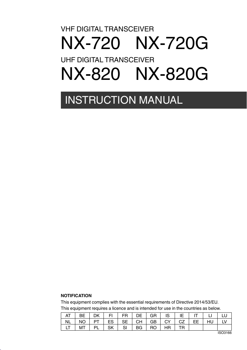
NOTIFICATION
This equipment complies with the essential requirements of Directive 2014/53/EU.
This equipment requires a licence and is intended for use in the countries as below.
AT BE DK FI FR DE GR IS IE IT LI LU
NL NO PT ES SE CH GB CY CZ EE HU LV
LT MT PL SK SI BG RO HR TR
ISO3166

The AMBE+2TM voice coding Technology embodied in this product is protected by intellectual property
rights including patent rights, copyrights and trade secrets of Digital Voice Systems, Inc. This voice
coding Technology is licensed solely for use within this Communications Equipment. The user of this
Technology is explicitly prohibited from attempting to extract, remove, decompile, reverse engineer,
or disassemble the Object Code, or in any other way convert the Object Code into a human-readable
form. U.S. Patent Nos. #8,315,860, #8,595,002, #6,199,037, #6,912,495, #8,200,497, #7,970,606,
and #8,359,197.
Firmware Copyrights
The title to and ownership of copyrights for firmware embedded in KENWOOD product memories
are reserved for JVC KENWOOD Corporation.
i
THANK YOU
We are grateful you have chosen KENWOOD for your personal mobile applications.
This instruction manual covers only the basic operations of your mobile radio. Ask your dealer for
information on any customized features they may have added to your radio.
NOTICES TO THE USER
◆ Government law prohibits the operation of unlicensed transmitters within the territories under
government control.
◆ Illegal operation is punishable by fi ne and/or imprisonment.
◆ Refer service to qualifi ed technicians only.
SAFETY: It is important that the operator is aware of, and understands, hazards
common to the operation of any transceiver.
◆ EXPLOSIVE ATMOSPHERES (GASES, DUST, FUMES, etc.)
Turn OFF your transceiver while taking on fuel or while parked in gasoline service stations. Do
not carry spare fuel containers in the trunk of your vehicle if your transceiver is mounted in the
trunk area.
◆ INJURY FROM RADIO FREQUENCY TRANSMISSIONS
Do not operate your transceiver when somebody is either standing near to or touching the
antenna, to avoid the possibility of radio frequency burns or related physical injury.
◆ DYNAMITE BLASTING CAPS
Operating the transceiver within 500 feet (150 m) of dynamite blasting caps may cause them
to explode. Turn OFF your transceiver when in an area where blasting is in progress, or where
“TURN OFF TWO-WAY RADIO” signs have been posted. If you are transporting blasting caps
in your vehicle, make sure they are carried in a closed metal box with a padded interior. Do not
transmit while the caps are being placed into or removed from the container.
Information on Disposal of Old Electrical and Electronic Equipment and Batteries (applicable
for countries that have adopted separate waste collection systems)
Products and batteries with the symbol (crossed-out wheeled bin) cannot be
disposed as household waste.
Old electrical and electronic equipment and batteries should be recycled at a
facility capable of handling these items and their waste byproducts.
Contact your local authority for details in locating a recycle facility nearest to you.
Proper recycling and waste disposal will help conserve resources whilst
preventing detrimental effects on our health and the environment.
ii
CONTENTS
GETTING STARTED ......................................................................................1
GETTING ACQUAINTED ...............................................................................3
PROGRAMMABLE FUNCTIONS .................................................................. 5
BASIC OPERATIONS ....................................................................................6
SCAN .............................................................................................................8
FleetSync: ALPHANUMERIC 2-WAY PAGING FUNCTION .......................10
5-TONE SIGNALING ...................................................................................12
DTMF CALLS...............................................................................................13
ADVANCED OPERATIONS .........................................................................15
BACKGROUND OPERATIONS ...................................................................19
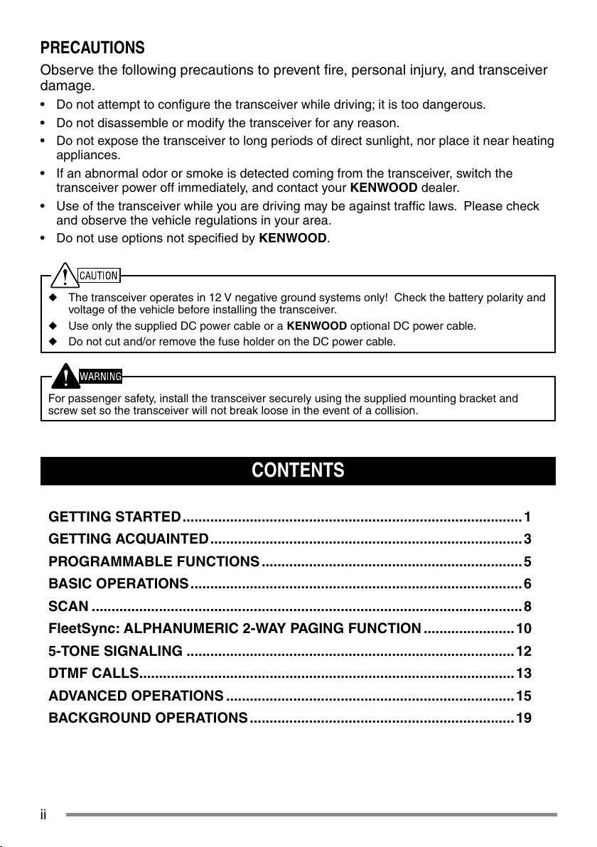
PRECAUTIONS
Observe the following precautions to prevent fi re, personal injury, and transceiver
damage.
• Do not attempt to confi gure the transceiver while driving; it is too dangerous.
• Do not disassemble or modify the transceiver for any reason.
• Do not expose the transceiver to long periods of direct sunlight, nor place it near heating
appliances.
• If an abnormal odor or smoke is detected coming from the transceiver, switch the
transceiver power off immediately, and contact your KENWOOD dealer.
• Use of the transceiver while you are driving may be against traffi c laws. Please check
and observe the vehicle regulations in your area.
• Do not use options not specifi ed by KENWOOD.
◆ The transceiver operates in 12 V negative ground systems only! Check the battery polarity and
voltage of the vehicle before installing the transceiver.
◆ Use only the supplied DC power cable or a KENWOOD optional DC power cable.
◆ Do not cut and/or remove the fuse holder on the DC power cable.
For passenger safety, install the transceiver securely using the supplied mounting bracket and
screw set so the transceiver will not break loose in the event of a collision.
1
GETTING STARTED
Note: The following instructions are for use by your KENWOOD dealer, an authorized KENWOOD
service facility, or the factory.
SUPPLIED ACCESSORIES
Carefully unpack the transceiver. We recommend that you identify the items listed below
before discarding the packing material. If any items are missing or have been damaged
during shipment, fi le a claim with the carrier immediately.
DC power cable (with fuses). . . . . . . . . . . . . . . . . . . . . . . . . . . . . . . . . . . . . . . . . . . . . . . . . . . . . . 1
• 15 A fuse . . . . . . . . . . . . . . . . . . . . . . . . . . . . . . . . . . . . . . . . . . . . . . . . . . . . . . . . . . . . . . . . . 2
Mounting Bracket . . . . . . . . . . . . . . . . . . . . . . . . . . . . . . . . . . . . . . . . . . . . . . . . . . . . . . . . . . . . . . 1
Screw set
• 5 x 16 mm self-tapping screw. . . . . . . . . . . . . . . . . . . . . . . . . . . . . . . . . . . . . . . . . . . . . . . . . .4
• M4 x 6 mm hex-headed screw with washer . . . . . . . . . . . . . . . . . . . . . . . . . . . . . . . . . . . . . . . 4
• Spring washer . . . . . . . . . . . . . . . . . . . . . . . . . . . . . . . . . . . . . . . . . . . . . . . . . . . . . . . . . . . . . 4
• Flat washer. . . . . . . . . . . . . . . . . . . . . . . . . . . . . . . . . . . . . . . . . . . . . . . . . . . . . . . . . . . . . . . . 4
Instruction manual . . . . . . . . . . . . . . . . . . . . . . . . . . . . . . . . . . . . . . . . . . . . . . . . . . . . . . . . . . . . . 1
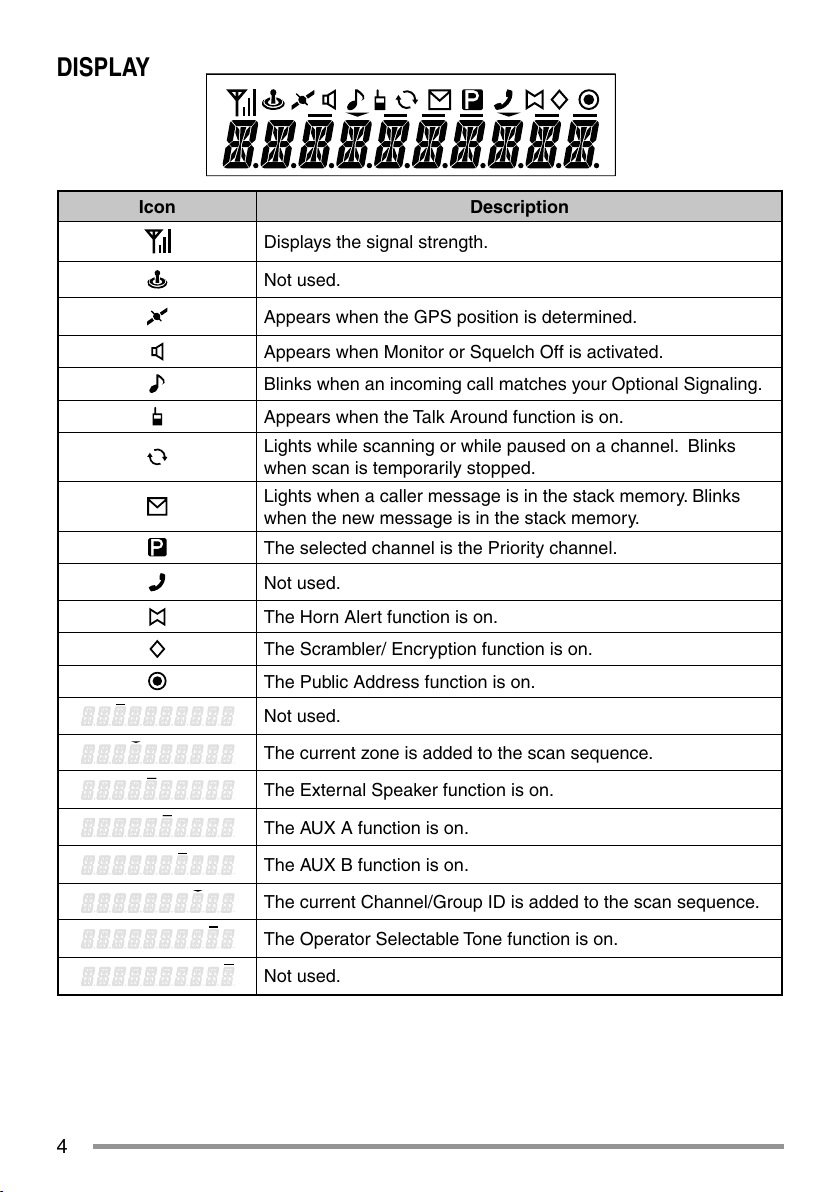
PREPARATION
Various electronic equipment in your vehicle may malfunction if they are not properly protected from
the radio frequency energy which is present while transmitting. Typical examples include electronic
fuel injection, anti-skid braking, and cruise control. If your vehicle contains such equipment, consult
the dealer for the make of vehicle and enlist his/her aid in determining if they will perform normally
while transmitting.
■ Power Cable Connection
The transceiver operates in 12 V negative ground systems only! Check the battery polarity and
voltage of the vehicle before installing the transceiver.
1 Check for an existing hole, conveniently located in the fi rewall, where the power
cable can be passed through.
• If no hole exists, use a circle cutter to drill a hole, then install a rubber grommet.
2 Run the power cable through the fi rewall and into the engine compartment.
3 Connect the red lead to the positive (+) battery terminal and the black lead to the
negative (–) battery terminal.
• Place the fuse as close to the battery as possible.
4 Coil the surplus cable and secure it with a retaining band.
• Be sure to leave enough slack in the cables so the transceiver can be removed
for servicing while keeping the power applied.

2
■ Installing the Transceiver
For passenger safety, install the transceiver securely using the supplied mounting bracket and
screw set, so the transceiver will not break loose in the event of a collision.
Note: Before installing the transceiver, check how far the mounting screws will extend below
the surface. When drilling mounting holes, be careful not to damage vehicle wiring or parts.
1 Mark the position of the holes in the dash, using the mounting bracket as a
template. Using a 4.2 mm (5/32 inch) drill bit, drill the holes, then attach the
mounting bracket using the supplied screws.
• Mount the transceiver within easy reach of the user and where there is suffi cient
space at the rear of the transceiver for cable connections.
2 Connect the antenna and the supplied power cable to the transceiver.
3 Slide the transceiver into the mounting bracket and secure it using the supplied hex-
headed screws.
4 Mount the microphone hanger in a location where it will be within easy reach of the
user.
• The microphone and microphone cable should be mounted in a place where
they will not interfere with the safe operation of the vehicle.
When replacing the fuse in the DC power cable, be sure to replace it with a fuse of the same
value. Never replace a fuse with one that is rated with a higher value.
M4 x 6 mm
Hex-headed screw
DC power cable
Mounting bracket
Antenna
connector
Power input
connector
Fuse
Black (–) cable
Red (+) cable
12 V vehicle
battery
Optional Microphone
5 x 16 mm
Self-tapping screw
Spring
washer
Flat
washer

3
GETTING ACQUAINTED
FRONT AND REAR VIEWS
① (Power) switch
Press to switch the transceiver ON or OFF.
②
/ keys
Press to activate their programmable functions {page 5}.
③
/ keys
Press to activate their programmable functions {page 5}.
④ TX/RX Indicator
Lights red while transmitting and green while receiving a signal. Flashes orange when
receiving an optional signaling call.
⑤ Microphone jack
Insert the microphone plug into this jack.
⑥ Status Indicator
Lights blue during a specifi ed mode, based on dealer programming.
⑦
/ S / A / <B / C> / ■ keys
Press to activate their programmable functions {page 5}.
⑧ Speaker
Internal speaker.
⑨ PTT switch
Press this switch, then speak into the microphone to call a station.
⑩ RFantenna connector
Connect the RF antenna to this connector.
⑪ ACC connector
Connect the ACC to this connector, via the KCT-60.
⑫ External speaker jack
Connect an external speaker to this jack.
⑬ GPS antenna connector <NX-720G/ NX-820G only>
Connect the KRA-40 GPS antenna to this connector.
⑭ Power input connector
Connect the DC Power Cable to this connector.
g
j
ab
c
n
m
k
e
f
h
i
l
d
4
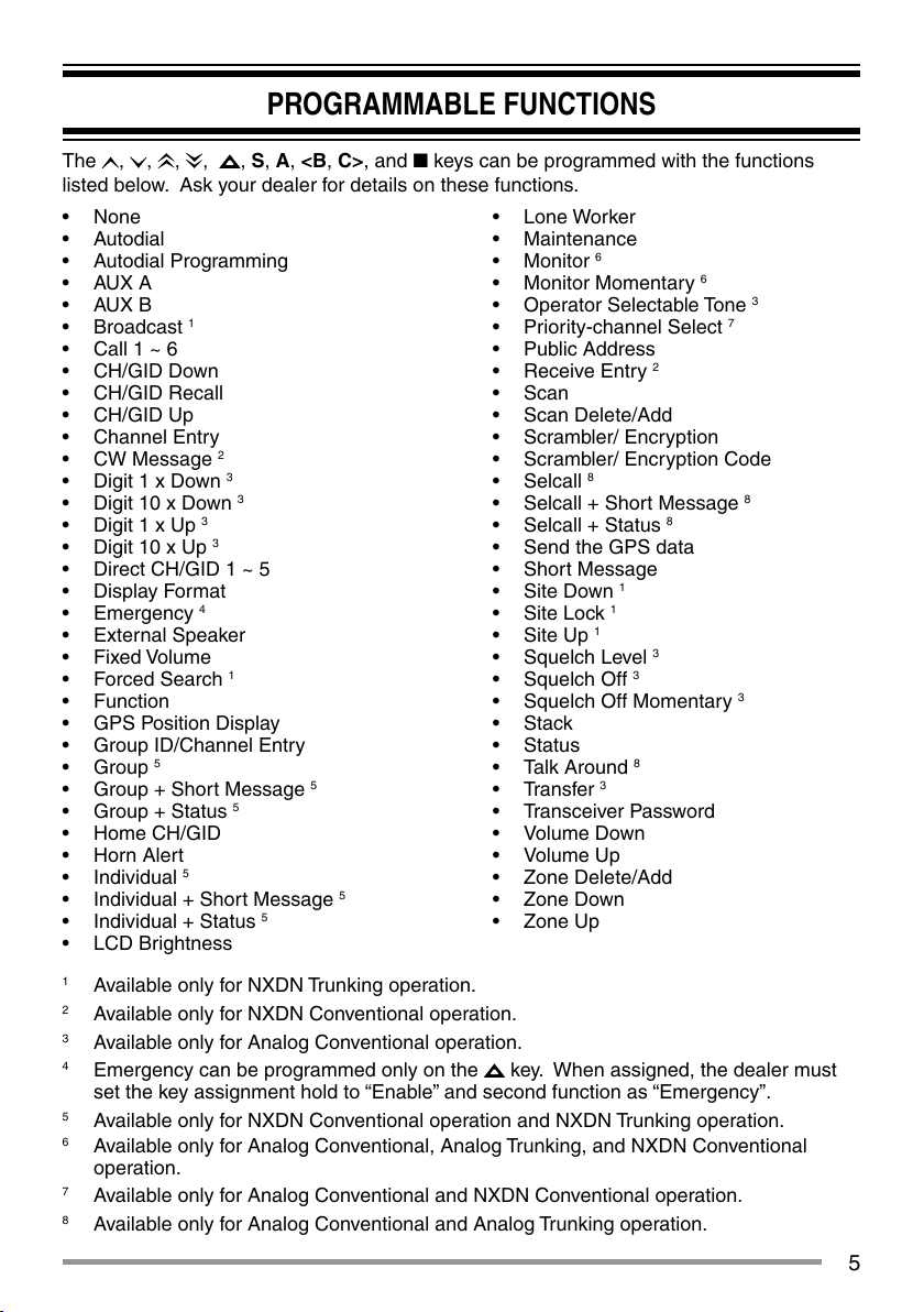
DISPLAY
Icon Description
Displays the signal strength.
Not used.
Appears when the GPS position is determined.
Appears when Monitor or Squelch Off is activated.
Blinks when an incoming call matches your Optional Signaling.
Appears when the Talk Around function is on.
Lights while scanning or while paused on a channel. Blinks
when scan is temporarily stopped.
Lights when a caller message is in the stack memory. Blinks
when the new message is in the stack memory.
The selected channel is the Priority channel.
Not used.
The Horn Alert function is on.
The Scrambler/ Encryption function is on.
The Public Address function is on.
Not used.
The current zone is added to the scan sequence.
The External Speaker function is on.
The AUX A function is on.
The AUX B function is on.
The current Channel/Group ID is added to the scan sequence.
The Operator Selectable Tone function is on.
Not used.
5
PROGRAMMABLE FUNCTIONS
The , , , , , S, A, <B, C>, and ■ keys can be programmed with the functions
listed below. Ask your dealer for details on these functions.
• None
• Autodial
• Autodial Programming
• AUX A
• AUX B
• Broadcast
1
• Call 1 ~ 6
• CH/GID Down
• CH/GID Recall
• CH/GID Up
• Channel Entry
• CW Message
2
• Digit 1 x Down
3
• Digit 10 x Down
3
• Digit 1 x Up
3
• Digit 10 x Up
3
• Direct CH/GID 1 ~ 5
• Display Format
• Emergency
4
• External Speaker
• Fixed Volume
• Forced Search
1
• Function
• GPS Position Display
• Group ID/Channel Entry
• Group
5
• Group + Short Message
5
• Group + Status
5
• Home CH/GID
• Horn Alert
• Individual
5
• Individual + Short Message 5
• Individual + Status
5
• LCD Brightness
• Lone Worker
• Maintenance
• Monitor
6
• Monitor Momentary
6
• Operator Selectable Tone
3
• Priority-channel Select
7
• Public Address
• Receive Entry
2
• Scan
• Scan Delete/Add
• Scrambler/ Encryption
• Scrambler/ Encryption Code
• Selcall
8
• Selcall + Short Message
8
• Selcall + Status
8
• Send the GPS data
• Short Message
• Site Down
1
• Site Lock
1
• Site Up
1
• Squelch Level
3
• Squelch Off
3
• Squelch Off Momentary
3
• Stack
• Status
• Talk Around
8
• Transfer
3
• Transceiver Password
• Volume Down
• Volume Up
• Zone Delete/Add
• Zone Down
• Zone Up
1
Available only for NXDN Trunking operation.
2
Available only for NXDN Conventional operation.
3
Available only for Analog Conventional operation.
4
Emergency can be programmed only on the
key. When assigned, the dealer must
set the key assignment hold to “Enable” and second function as “Emergency”.
5
Available only for NXDN Conventional operation and NXDN Trunking operation.
6
Available only for Analog Conventional, Analog Trunking, and NXDN Conventional
operation.
7
Available only for Analog Conventional and NXDN Conventional operation.
8
Available only for Analog Conventional and Analog Trunking operation.
6
BASIC OPERATIONS
SWITCHING POWER ON/ OFF
Press to switch the transceiver ON.
• A beep sounds and the display illuminates.
• If the Transceiver Password function is programmed, “PASSWORD” will appear on the
display.
Press
again to switch the transceiver OFF.
■ Transceiver Password
To enter the password:
1 Press the
/ key to select a digit.
• When using a microphone DTMF keypad, simply enter the password digits and
proceed to step 4.
2 Press the S or
key to accept the entry and move to the next digit.
• Press the A or # key to delete an incorrect digit.
• Press the C> key to delete all.
3 Repeat steps 1 and 2 to enter the entire password.
• The password can contain a maximum of 6 digits.
4 Press the S or
key to confi rm the entered password.
• If you enter an incorrect password, an error tone sounds and the transceiver
remains locked.
ADJUSTING THE VOLUME
Press the [Volume Up] key to increase the volume. Press the [Volume Down] key to
decrease the volume.
If Squelch Off has been programmed onto a key, you can use that function to listen to
background noise while adjusting the volume level.
SELECTING A ZONE AND CHANNEL/GROUP ID
Select the desired zone and channel/group ID using the keys programmed as [Zone Up]/
[Zone Down] and [CH/GID Up]/ [CH/GID Down].
• You can program names for zones and channels/group IDs with up to 10 characters.
• If the Voice Announce function has been set up by your dealer, an audio voice will
announce the new zone, channel and group number when changing the zone, channel,
and/or group.
TRANSMITTING
1 Select the desired zone and channel/group ID.
2 Press the key programmed as [Monitor] or [Squelch Off] to check whether or not the
channel is free.

7
• If the channel is busy, wait until it becomes free.
3 Press the PTT switch and speak into the microphone. Release the PTT switch to
receive.
• For best sound quality, hold the transceiver approximately 1.5 inches (3 ~ 4 cm)
from your mouth.
■ Making Group Calls (Digital)
If a key has been programmed as [Group], you can select a group ID from the list to
make a call to those parties on a Conventional channel.
To select a group ID:
1 Press the key programmed as [Group].
2 Press the
/ key to select a group ID/name from the list.
3 Press and hold the PTT switch to make the call.
• Speak into the transceiver as you would during a normal transmission.
■ Making Individual Calls (Digital)
If a key has been programmed with [Individual], you can make calls to specifi c
persons.
1 Press the key programmed as [Individual].
2 Press the
/ key to select a unit ID from the list.
• When using a microphone DTMF keypad, you can enter a unit ID directly.
3 Press and hold the PTT switch to make the call.
• Speak into the transceiver as you would during a normal transmission.
RECEIVING
Select the desired zone and channel. If signaling has been programmed on the selected
channel, you will hear a call only if the received signal matches your transceiver settings.
Note: Signaling allows your transceiver to code your calls. This will prevent you from listening to
unwanted calls. Refer to “SIGNALING” on page 16 for details.
■ Receiving Group Calls (Digital)
When you receive a group call on a Conventional channel and the received group ID
matches the ID set up on your transceiver, you can hear the caller’s voice.
When you receive a group call on a Trunking channel, the transceiver automatically
switches to the communications channel to receive the call.
■ Receiving Individual Calls (Digital)
When you receive an individual call, a ringing tone will sound and the caller’s ID will
appear on the display. To respond to the call, press and hold the PTT switch and speak
into the transceiver as you would during a normal transmission.
8
SCAN
Scan monitors for signals on the transceiver channels. While scanning, the transceiver
checks for a signal on each channel and only stops if a signal is present.
To begin scanning, press the key programmed as [Scan].
• The
indicator appears.
• When a signal is detected on a channel, Scan pauses at that channel. The transceiver
will remain on the busy channel until the signal is no longer present, at which time Scan
resumes.
To stop scanning, press the [Scan] key again.
Note: To use Scan, there must be at least 2 channels in the scan sequence.
TEMPORARY CHANNEL LOCKOUT
During scan, you can temporarily remove specifi c channels from the scanning sequence by
selecting them and pressing the key programmed as [Scan Delete/Add].
• The channel is no longer scanned. However, when scanning is ended and restarted,
the channels are reset and deleted channels will again be in the scanning sequence.
PRIORITY SCAN
If a Priority channel has been programmed, the transceiver will automatically change to the
Priority channel when a call is received on that channel, even if a call is being received on
a normal channel.
• The
indicator appears when the selected channel is the Priority channel (depending
on dealer setting).
SCAN REVERT
The Scan Revert channel is the channel selected when you press the PTT switch to
transmit during scan. Your dealer can program one of the following types of Scan Revert
channels:
• Selected: The last channel selected before scan.
• Selected + Talkback: Same as “Selected”, plus you can respond to calls on the
channel at which scan is paused.
• Priority: The Priority channel.
• Priority + Talkback: Same as “Priority”, plus you can respond to calls on the channel
at which scan is paused.
• Last Called + Selected: The last channel on which you receive a call.
9
SCAN DELETE/ADD
You can add and remove zones and/or channels/group IDs to and from your scan list.
1 Select your desired zone and/or channel/group ID.
2 Press the key programmed as [Zone Delete/Add] (to add/remove zones) or [Scan
Delete/Add] (to add/remove channels/group IDs).
• You can also press and hold the key programmed as [Scan Delete/Add] to add/
remove zones.
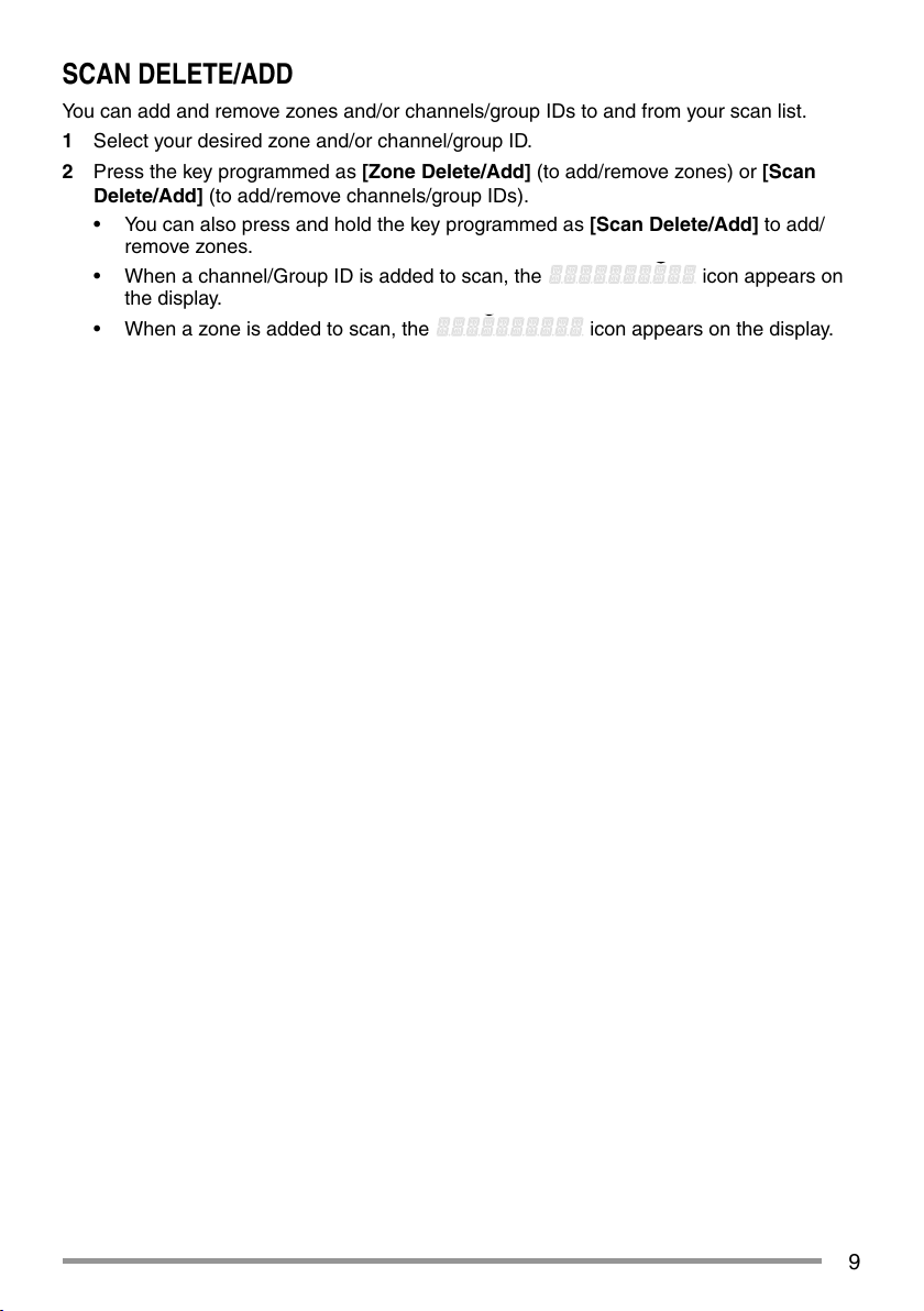
• When a channel/Group ID is added to scan, the
icon appears on
the display.
• When a zone is added to scan, the
icon appears on the display.
10
FleetSync: ALPHANUMERIC 2-WAY PAGING FUNCTION
FleetSync is an Alphanumeric 2-way Paging Function, and is a protocol owned by
JVC KENWOOD Corporation.
Note: This function is available only in analog operation.
SELCALL (SELECTIVE CALLING)
A Selcall is a voice call to a station or group of stations.
■ Transmitting
1 Select your desired zone and channel.
2 Press the key programmed as [Selcall] to enter Selcall mode.
3 Press the
/ key to select the station you want to call.
4 Press the PTT switch and begin your conversation.
■ Receiving
An alert tone will sound and the transceiver will enter Selcall mode. The calling station’s
ID will appear when a Selcall is received. You can respond to the call by pressing the
PTT switch and speaking into the microphone.
■ Identifi cation Codes
An ID code is a combination of a 3-digit Fleet number and a 4-digit ID number. Each
transceiver has its own ID.
• Enter a Fleet number (100 ~ 349) to make a group call.
• Enter an ID number (1000 ~ 4999) to make an individual call in your fl eet.
• Enter a Fleet number to make a call to all units in the selected fl eet (Fleet call).
STATUS MESSAGE
You can send and receive 2-digit Status messages which may be decided in your talk
group. Messages can contain up to 16 alphanumeric characters. Status messages range
from 10 to 99 (80 ~ 99 are reserved for special messages).
A maximum of 15 received messages (combined status messages and short messages)
can be stored in the stack memory of your transceiver.
■ Transmitting
1 Select your desired zone and channel.
2 Press the key programmed as [Status] to enter Status mode (proceed to step 5) or
[Selcall + Status] to enter Selcall mode (proceed to step 3).
3 Press the
/ key to select the station you want to call.
• If Manual Dialing is enabled, you can enter a station ID by using the microphone
DTMF keypad by pressing and holding the S or
key. Repeat this process
until the entire ID is entered.
4 Press the S or
key to enter Status mode.

11
5 Press the / key to select the status you want to transmit.
• If Manual Dialing is enabled, you can enter a station ID by using the microphone
DTMF keypad (refer to step 3, above).
6 Press the PTT switch to initiate the call.
• “COMPLETE” appears on the display when the status has been successfully
transmitted.
■ Receiving
A calling ID or text message will appear when a Status call is received. Press any key
to return to normal operation.
■ Reviewing Messages in the Stack Memory
1 Press the key programmed as [Stack], or press and hold the key programmed as
[Selcall], [Status], or [Selcall + Status] to enter Stack mode.
• The last received message is displayed.
2 Press the
/ key to select the desired message.
• Message types are identifi ed as follows:
ID: Caller ID, ST: Status Message, ME: Short Message
• Press and hold the S or
key for 1 second to cycle the display information as
follows:
ID Name > Status/Short Message > CH/GID
3 Press the
key to return to normal operation.
• To delete the selected message, press the A or # key. To confi rm the deletion,
Press the S or
key.
• To delete all messages, press and hold the A or # key for 1 second. To confi rm
the deletion, Press the S or
key.
SHORT MESSAGES
This transceiver can receive short data messages which contain a maximum of 48
characters.
• Received short messages are displayed the same as Status messages. A maximum of
15 received messages (combined status messages and short messages) can be stored
in the stack memory of your transceiver.
GPS REPORT
GPS data can be manually transmitted by pressing the key programmed as [Send the
GPS data]. If set up by your dealer, GPS data may be automatically transmitted at a
preset time interval.
• When using the NX-720G/ NX-820G, you must connect a KRA-40 GPS antenna.
• When using the NX-720/ NX-820, you must connect an external GPS unit.
• When the power is turned ON and/or the reception condition of the GPS satellite is
poor, positioning completion time may take longer.
12
5-TONE SIGNALING
5-tone Signaling is enabled or disabled by your dealer. This function opens the squelch
only when the transceiver receives the 5 tones programmed in your transceiver.
Transceivers that do not transmit the correct tones will not be heard.
SELCALL (SELECTIVE CALLING)
A Selcall is a voice call to a station or group of stations.
■ Transmitting
1 Select your desired zone and channel.
2 Press the key programmed as [Selcall] to enter Selcall mode.
3 Press the
/ key to select the station you want to call.
• When using a microphone DTMF keypad, you can directly enter the station ID.
4 Press the key programmed as [Call 1] to [Call 6] and begin your conversation.
Note: Additionally, you can also use the keys programmed as [Digit 1x Down], [Digit 1x
Up], [Digit 10x Down], and [Digit 10x Up] to adjust the Selcall number. [Digit 1x Up/Down]
increases/decreases the Selcall number by 1 each time the key is pressed. [Digit 10x Up/
Down] increases/decreases the Selcall number by 10 each time the key is presse
■ Receiving
When you receive a call containing the correct tones, the transceiver will enter Selcall
mode. An alert tone will sound and the calling station’s ID appears on the display.
Press any key to return to normal operation.
STATUS MESSAGE
You can send and receive Status messages which may be decided in your talk group.
Messages can contain up to 16 alphanumeric characters.
A maximum of 15 received messages can be stored in the stack memory of your
transceiver.
■ Transmitting
1 Select your desired zone and channel.
2 Press the key programmed as [Status] to enter Status mode (proceed to step 5) or
[Selcall + Status] to enter Selcall mode (proceed to step 3).
3 Press the
/ key to select the station you want to call.
• In Selcall List Mode, press and hold the S or
key for 1 second to enter Manual
Input mode. Press the
/ key to select the digit you want to change, then
rotate the Selector to change the Code Up or Down. Or, you can enter the Code
directly by using the microphone DTMF keypad.
4 Press the S or
key to enter Status mode.
5 Press the
/ key to select the status you want to transmit.
13
• In Selcall List Mode, press and hold the S or key for 1 second to enter Manual
Input mode. Press the
/ key to select the digit you want to change, then
rotate the Selector to change the Code Up or Down. Or, you can enter the Code
directly by using the microphone DTMF keypad.
6 Press the key programmed as [Call 1] to [Call 6] to initiate the call.
■ Receiving
A calling ID or text message will appear when a Status call is received. Press any key
to return to normal operation.
14
DTMF (DUAL TONE MULTI FREQUENCY) CALLS
MANUAL DIALING
1 Press and hold the PTT switch.
2 Enter the desired digits using the microphone DTMF keypad.
• If you release the PTT switch, transmit mode will end even if the complete number
has not been sent.
• If the Keypad Auto PTT function has been enabled by your dealer, you do not need
to press the PTT switch to transmit; you can make the call simply by pressing the
microphone DTMF keys.
■ Store & Send
1 Press the key programmed as [Autodial].
2 Enter up to 30 digits using the microphone DTMF keypad.
3 Press the PTT switch to make the call.
AUTODIAL
Autodial allows you to quickly call DTMF numbers that have been programmed onto your
transceiver.
1 Press the key programmed as [Autodial].
• The fi rst entry in the Autodial list appears on the display.
2 Press the
/ key to select an autodial list number.
• You can also enter a number from 01 ~ 32 directly using the microphone DTMF
keypad.
3 Press the PTT switch to make the call.
■ Storing an Autodial Entry
1 Press the key programmed as [Autodial Programming].
2 Press the
/ key to select a memory location number.
3 Press the S or
key to enter a name for the list number.
4 Press the
/ key to select a digit.
5 Press the C> key to accept the entered digit and move the cursor to the right.
• Press the A or # key to delete an incorrect digit. Press and hold the A or # key
to delete all digits.
6 Repeat steps 4 and 5 to enter the entire name.
7 Press the S or
key to accept the name and enter a number.
8 Press the
/ key to select a digit.
• You can also enter digits directly using the microphone DTMF keypad.
9 Press the S or
key to accept the entered digit.
• Press the A or # key to delete an incorrect digit. Press and hold the A or # key
to delete all digits.
10 Repeat steps 8 and 9 to enter the entire number.
15
11 Press the S or key to accept the number and store the entry.
■ Removing an Autodial Entry
1 Press the key programmed as [Autodial Programming].
2 Press the
/ key to select a memory location number.
3 Press the A or # key.
• “DELETE” appears on the display.
• Additionally, you can press and hold the A or # key to delete all entries.
4 Press the S or
key key to confi rm the deletion.
REDIALING
1 Press the key programmed as [Autodial].
2 Press the
key, then press the 0 key.
• If there is no data in the redial memory, an error tone will sound.
3 Press the PTT switch to make the call.
STUN
This function is used when a transceiver is stolen or lost. When the transceiver receives a
call containing a stun code, the transceiver becomes disabled. The stun code is cancelled
when the transceiver receives a call with a revive code.
• “STUN” appears on the display while the transceiver is stunned.
16
ADVANCED OPERATIONS
EMERGENCY CALLS
If your transceiver has been programmed with the Emergency function, you can make
emergency calls.
1 Press and hold the key programmed as [Emergency].
• Ask your dealer for the length of time necessary to hold this key before the
transceiver enters Emergency mode.
• When the transceiver enters Emergency mode, it will change to the Emergency
channel and begin transmitting based on how it is set up by your dealer.
2 To exit Emergency mode, press the [Emergency] key again.
• If the Emergency mode completes a preset number of cycles, Emergency mode will
automatically end and the transceiver will return to the zone and channel that was in
use before Emergency mode was entered.
Note:
◆ Your dealer can set the transceiver to emit a tone when transmitting in Emergency mode.
◆ Your dealer can set the transceiver to emit tones and received signals as normal, or mute the
speaker during Emergency operation.
SCRAMBLER (ANALOG) / ENCRYPTION (DIGITAL)
■ Secure (Encrypted) Transmission
Press the key programmed as [Scrambler/ Encryption] to switch the transceiver to
secure (encrypted) transmission.
• The
icon appears on the display.
• Pressing the PTT switch after the Scrambler or Encryption function has been turned
ON encrypts the transmitted signal.
■ Selecting the Scrambler Code or Encryption Key
1 Press the key programmed as [Scrambler/ Encryption Code] to enter Code or Key
Selection mode.
2 Press the
/ key to increase or decrease the code or key.
• There are 16 available Scrambler codes or Encryption keys (1 ~ 16).
Note: This function cannot be used in certain countries. Contact your KENWOOD dealer for further
information.
SIGNALING
■ Quiet Talk (QT)/ Digital Quiet Talk (DQT)
Your dealer may have programmed QT or DQT signaling on your transceiver channels.
A QT tone/ DQT code is a sub-audible tone/code which allows you to ignore (not hear)
calls from other parties who are using the same channel.
Operator Selectable Tone (OST)
If a key has been programmed with [OST], you can reprogram the QT/DQT settings on
each of your channels.
17
1 Select your desired channel.
2 Press and hold the key programmed as [OST] for 1 second.
3 Press the
/ key to select your desired tone or code.
• Your dealer can set up to 40 tones/codes.
4 When you have fi nished operating using OST, press the [OST] key again to turn the
OST function OFF.
■ Radio Access Number (RAN)
RAN is a new signaling system designed for digital radio communications.
When a channel is set up with a RAN, squelch will only open when a call containing
a matching RAN is received. If a call containing a different RAN is made on the same
channel you are using, you will not hear the call. This allows you to ignore (not hear)
calls from other parties who are using the same channel.
■ Optional Signaling
Your dealer may also program several types of optional signaling for your transceiver
channels.
5-tone Signaling: Refer to “SELCALL (SELECTIVE CALLING)” on page 12.
DTMF Signaling: DTMF Signaling opens the squelch only when the transceiver
receives a call containing a matching DTMF code.
FleetSync Signaling: Refer to “SELCALL (SELECTIVE CALLING)” on page 10.
NXDN ID Signaling: NXDN ID is an optional signaling system available only for digital
communications.
MONITOR/ SQUELCH OFF
You can use the key programmed as [Monitor] or [Squelch Off] to listen to weak signals
that you cannot hear during normal operation and to adjust the volume when no signals are
present on your selected channel.
• The
icon appears on the display while Monitor or Squelch Off is activated.
Your dealer can program a key with one of four Monitor/Squelch Off functions:
• Monitor: Press to deactivate QT, DQT, DTMF, 5-tone, or FleetSync Signaling. Press
again to return to normal operation.
• Monitor Momentary: Press and hold to deactivate QT, DQT, DTMF, 5-tone or
FleetSync Signaling. Release to return to normal operation.
• Squelch Off: Press to hear background noise. Press again to return to normal
operation.
• Squelch Off Momentary: Press and hold to hear background noise. Release to return
to normal operation.
■ Squelch Level
If a key has been programmed as [Squelch Level], you can readjust your transceiver’s
squelch level:
1 Press the key programmed as [Squelch Level].
• The
current squelch level appears on the display.
2 Press the / key to select your desired squelch level from 0 to 9.
3 Press the S or
key to store the new setting.
18
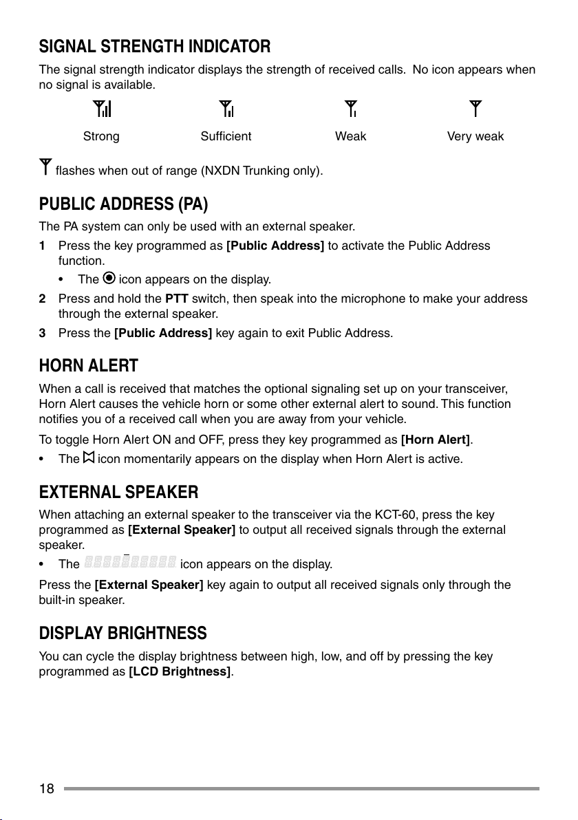
SIGNAL STRENGTH INDICATOR
The signal strength indicator displays the strength of received calls. No icon appears when
no signal is available.
Strong Suffi cient Weak Very weak
fl ashes when out of range (NXDN Trunking only).
PUBLIC ADDRESS (PA)
The PA system can only be used with an external speaker.
1 Press the key programmed as [Public Address] to activate the Public Address
function.
• The
icon appears on the display.
2 Press and hold the PTT switch, then speak into the microphone to make your address
through the external speaker.
3 Press the [Public Address] key again to exit Public Address.
HORN ALERT
When a call is received that matches the optional signaling set up on your transceiver,
Horn Alert causes the vehicle horn or some other external alert to sound. This function
notifi es you of a received call when you are away from your vehicle.
To toggle Horn Alert ON and OFF, press they key programmed as [Horn Alert].
• The
icon momentarily appears on the display when Horn Alert is active.
EXTERNAL SPEAKER
When attaching an external speaker to the transceiver via the KCT-60, press the key
programmed as [External Speaker] to output all received signals through the external
speaker.
• The icon appears on the display.
Press the [External Speaker] key again to output all received signals only through the
built-in speaker.
DISPLAY BRIGHTNESS
You can cycle the display brightness between high, low, and off by pressing the key
programmed as [LCD Brightness].
19
BACKGROUND OPERATIONS
TIME-OUT TIMER (TOT)
The Time-out Timer prevents you from using a channel for an extended duration. If you
continuously transmit for a preset time, the transceiver will stop transmitting and an alert
tone will sound. Release the PTT switch.
AUXILIARY PORT
Press the key programmed as [AUX A] or [AUX B] to activate the auxiliary port. The
auxiliary port is used with external devices.
• The
icon appears on the display when the auxiliary A port is active.
• The
icon appears on the display when the auxiliary B port is active.
BUSY CHANNEL LOCKOUT (BCL)
If BCL is set up by your dealer, you will be unable to transmit if the channel is already in
use.
• “BUSY” appears on the display when you press the PTT switch. Use a different
channel or wait until the channel becomes free.
If your dealer has programmed BCL Override for your transceiver, you can override the
BCL by pressing the PTT switch again, immediately after releasing it, when the channel is
busy.
CONTROL CHANNEL HUNT
On digital Trunking channels, the transceiver automatically searches for a control channel.
• While searching for a control channel, the antenna icon will fl ash and no signals can be
received.
PTT ID
PTT ID is the transceiver unique ID code which is sent each time the PTT switch is pressed
and/or released. (PTT ID can be made only in analog operation.)
COMPANDER
If programmed by your dealer for a channel, the compander will remove excessive noise
from transmitted signals, providing higher clarity of signals. (The compander is used only in
analog operation.)
• Your dealer must set the compander for both the transmit side and the receive side in
order for the compander to operate.
TRANSMIT POWER
Your dealer has programmed a transmit power level for each channel. Power levels can be
high or low.


MODE D’EMPLOI
ÉMETTEUR-RÉCEPTEUR NUMÉRIQUE VHF
NX-720 NX-720G
ÉMETTEUR-RÉCEPTEUR NUMÉRIQUE UHF
NX-820 NX-820G
NOTIFICATION
Cet équipement est conforme aux principals exigences de la Directive 2014/53/EU.
Cet équipement nécessite un contrat de licence et il est destiné à être utilisé dans les
pays ci-dessous
AT BE DK FI FR DE GR IS IE IT LI LU
NL NO PT ES SE CH GB CY CZ EE HU LV
LT MT PL SK SI BG RO HR TR
ISO3166

La technologie de codage de la voix AMBE +2™ intégrée dans ce produit est protégée par des
droits sur la propriété intellectuelle y compris les droits de brevet, les droits d’auteur et les secrets
de fabrication du Digital Voice Systems, Inc. Cette technologie de codage de la voix est autorisée
uniquement pour une utilisation avec cet équipement de communication. Il est formellement interdit
de la part de l’utilisateur de cette technologie d’essayer d’extraire, de retirer, de décompiler, de
procéder à une ingénierie inverse, ou de démonter le code objet, ou d’aucune autre manière que ce
soit de convertir l’objet code dans un langage humain intelligible. Brevets américains n°. #8,315,860,
#8,595,002, #6,199,037, #6,912,495, #8,200,497, #7,970,606 et #8,359,197.
Droits d’auteur du micrologiciel
Le titre et la propriété des droits d’auteur pour le micrologiciel intégré dans la mémoire du produit
KENWOOD sont réservés pour JVC KENWOOD Corporation.

F-i
MERCI
Nous sommes heureux que vous ayez choisi KENWOOD pour vos applications mobiles
personnelles.
Ce mode d’emploi ne reprend que le fonctionnement de base de votre radio mobile. Renseignez-
vous auprès de votre revendeur pour de plus amples informations relatives aux fonctions
personnalisées qui ont pu être ajoutées à votre radio.
AVIS AUX UTILISATEURS
◆ Une loi gouvernementale interdit l’usage sans licence des émetteurs radio sur les territoires
régis par cette autorité gouvernementale.
◆ Une utilisation illégale est passible d’amende ou d’emprisonnement.
◆ Pour l’entretien et la réparation, confi ez l’appareil uniquement à des techniciens qualifi és.
SÉCURITÉ : Il est important que l’opérateur soit au courant des risques usuels associés à
l’exploitation d’un émetteur-récepteur.
◆ ATMOSPHÈRES EXPLOSIVES (GAZ, POUSSIÈRE, FUMÉE, etc.)
Mettez l’émetteur-récepteur hors tension lorsque vous faites le plein d’essence ou lorsque vous
garez votre véhicule dans une station-service. Ne transportez pas de bidons d’essence dans
le coffre arrière de votre véhicule si votre émetteur-récepteur est installé dans cette zone.
◆ BLESSURES RÉSULTANT DE LA TRANSMISSION DE FRÉQUENCES RADIO
Ne faites pas fonctionner l’émetteur-récepteur lorsque quelqu’un se trouve à proximité
de ou touche l’antenne, de manière à éviter tout risque de brûlures occasionnées par les
radiofréquences et autres blessures connexes.
◆ DÉTONATEURS DE DYNAMITE
L’exploitation de l’émetteur-récepteur dans un rayon de 150 mètres d’un détonateur de
dynamite pourrait provoquer son explosion. Mettez votre émetteur-récepteur hors tension
lorsque vous êtes dans une zone de dynamitage en cours ou dans un endroit où des panneaux
d’avertissement demandent de mettre les émetteurs-récepteurs hors tension. Si vous
transportez des détonateurs dans votre véhicule, assurez-vous qu’ils se trouvent dans des
contenants métalliques fermés dont l’intérieur est matelassé. N’émettez jamais pendant qu’on
place ou qu’on sort les détonnateurs de leur contenant.
AVERTISSEMENT
Information sur l’élimination des anciens équipements électriques et électroniques et piles
électriques (applicable dans les pays de qui ont adopté des systèmes de collecte sélective)
Les produits et piles électriques sur lesquels le pictogramme (poubelle barrée)
est apposé ne
peuvent pas être éliminés comme ordures ménagères.
Les anciens équipements et batteries électriques et électroniques doivent être
recyclés sur des sites en mesure de traiter ces produits et leurs déchets.
Contactez vos autorités locales pour connaître le site de recyclage le plus proche.
Un recyclage adapté et l’élimination des déchets aideront à conserver les
ressources et à nous préserver des leurs effets nocifs sur notre santé et sur
l’environnement.
F-ii
PRÉCAUTIONS
Veuillez respecter les points suivants afi n d’éviter les risques d’incendie, de blessure corporelle
ou d’endommagement de l’émetteur-récepteur.
• Ne tentez pas de confi gurer l’émetteur-récepteur tout en conduisant, car cela est trop
dangeureux.
• Ne démontez et ne modifi ez sous aucun cas l’émetteur-récepteur.
• N’exposez pas l’émetteur-récepteur aux rayons directs du soleil pendant de longues périodes
et ne le placez pas près d’appareils chauffants.
• Si une odeur anormale ou de la fumée est générée par l’émetteur-récepteur, mettez
immédiatement l’émetteur-récepteur hors tension et contactez votre revendeur KENWOOD.
• Il est possible que l’utilisation de l’émetteur-récepteur lors de la conduite soit contraire aux
règles de circulation. Veuillez vérifi er et respecter les régulations routières de votre pays.
• N’utilisez pas les options non indiquées par KENWOOD.
◆ Cet émetteur-récepteur fonctionne uniquement avec un système de 12 V à masse négative!
Vérifi ez la polarité et la tension de la batterie du véhicule avant d’installer l’émetteur-récepteur.
◆ Utilisez uniquement le câble d’falimentation CC fourni ou un câble d’alimentation CC
KENWOOD en option.
◆ Ne pas couper et/ou retirer le support de fusible sur le câble d’alimentation CC.
Pour la sécurité du passager, et pour éviter que l’émetteur-récepteur ne se détache en cas de collision,
fi xez solidement l’émetteur-récepteur en utilisant le support de montage et l’ensemble des vis.
TABLE DES MATIÈRES
POUR DÉMARRER ............................................................................................. 1
FAMILIARISATION AVEC L’APPAREIL .............................................................. 3
FONCTIONS PROGRAMMABLES ..................................................................... 5
FONCTIONNEMENT DE BASE ........................................................................... 6
BALAYAGE .......................................................................................................... 8
FleetSync: TÉLÉAVERTISSEUR BIDIRECTIONNEL ALPHANUMÉRIQUE ... 10
SIGNALISATION À 5 TONALITÉS .................................................................... 12
APPELS DTMF (DOUBLE TONALITÉ MULTI-FRÉQUENCE).......................... 14
OPÉRATIONS AVANCÉES................................................................................ 16
OPÉRATIONS EN ARRIÈRE-PLAN .................................................................. 19
AVERTISSEMENT
ATTENTION
Table
PO

F-1
POUR DÉMARRER
Remarque : les instructions suivantes sont destinées à votre revendeur KENWOOD, un centre de
service agréé KENWOOD ou à l’usine de fabrication.
ACCESSOIRES FOURNIS
Déballez soigneusement l’émetteur-récepteur. Nous recommandons que vous identifi ez les
articles de la liste ci-dessous avant de vous débarrasser des matériaux d’emballage.
Si un article manque ou a été endommagé pendant l’expédition, remplissez immédiatement un
formulaire de plainte auprès du transporteur.
Câble d’alimentation CC (avec fusibles) . . . . . . . . . . . . . . . . . . . . . . . . . . . . . . . . . . . . . . . . . . . . .1
• Fusible 15 A . . . . . . . . . . . . . . . . . . . . . . . . . . . . . . . . . . . . . . . . . . . . . . . . . . . . . . . . . . . . . . . 2
Support de montage . . . . . . . . . . . . . . . . . . . . . . . . . . . . . . . . . . . . . . . . . . . . . . . . . . . . . . . . . . . . 1
Ensemble de vis
• Vis taraudeuse 5 x 16 mm . . . . . . . . . . . . . . . . . . . . . . . . . . . . . . . . . . . . . . . . . . . . . . . . . . . . 4
• Vis à tête hexagonale et rondelle M4 x 6 mm . . . . . . . . . . . . . . . . . . . . . . . . . . . . . . . . . . . . . 4
• Rondelle à ressort . . . . . . . . . . . . . . . . . . . . . . . . . . . . . . . . . . . . . . . . . . . . . . . . . . . . . . . . . . 4
• Rondelle ordinaire . . . . . . . . . . . . . . . . . . . . . . . . . . . . . . . . . . . . . . . . . . . . . . . . . . . . . . . . . . 4
Mode d’emploi . . . . . . . . . . . . . . . . . . . . . . . . . . . . . . . . . . . . . . . . . . . . . . . . . . . . . . . . . . . . . . . . 1
PRÉPARATION
Divers équipements électroniques de votre véhicule peuvent mal fonctionner s’ils ne sont pas
correctement protégés contre l’énergie radiofréquence produite pendant l’émission. Par exemple,
l’injection électronique, le dispositif anti-blocage de frein et le régulateur de vitesse automatique. Si votre
véhicule contient de tels équipements, consultez le revendeur de votre véhicule et demandez-lui son aide
pour déterminer s’ils fonctionneront normalement pendant une émission.
■ Connexion du câble d’alimentation
Cet émetteur-récepteur fonctionne uniquement avec un système de 12 V à masse négative! Vérifi ez
la polarité et la tension de la batterie du véhicule avant d’installer l’émetteur-récepteur.
1 Vérifi ez s’il existe déjà un trou placé de façon pratique dans le pare-feu, à travers lequel
le câble d’alimentation peut être passé.
• S’il n’y a pas de trou, utilisez un trépan pour percer un trou, puis installez un joint en
caoutchouc.
2 Faites passer le câble d’alimentation à travers le pare-feu jusqu’au compartiment du
moteur.
3 Connectez le fi l rouge à la borne positive (+) de la batterie et le fi l noir à la borne
négative (–) de la batterie.
• Placez le fusible aussi près que possible de la batterie.
4 Enroulez le câble en trop et fi xez-le avec une bande de retenue.
• Assurez-vous de laisser suffi samment de jeu aux câble de façon à ce que l’émetteur-
récepteur puisse être retiré pour réparation tout en restant connecté à l’alimentation.
AVERTISSEMENT
ATTENTION

F-2
■ Installation de l’émetteur-récepteur
Pour la sécurité du passager, et pour éviter que l’émetteur-récepteur ne se détache en cas de collision,
fi xez solidement l’émetteur-récepteur en utilisant le support de montage et l’ensemble des vis.
Remarque : Avant d’installer l’émetteur-récepteur, vérifi ez jusqu’où iront les vis de montage sous
la surface. Quand vous percez des trous de montage, faites attention de ne pas endommager le
câblage ou des pièces du véhicule.
1 Marquez la position des trous sur le tableau de bord, en utilisant le support de montage
comme repère. En utilisant une mèche de 4,2 mm, percez les trous, puis fi xez le support
de montage en utilisant les vis fournies.
• Montez l’émetteur-récepteur dans un endroit facile à atteindre pour l’utilisateur et où
il y a suffi samment d’espace à l’arrière de l’émetteur-récepteur pour les connexions.
2 Connectez l’antenne et le câble d’alimentation fourni à l’émetteur-récepteur.
3 Faites glisser l’émetteur-récepteur dans le support de montage et fi xez-le en utilisant les
vis à tête hexagonale fournies.
4 Montez le crochet à microphone dans un endroit facile d’accès pour l’utilisateur.
• Le microphone et le câble du microphone doivent être montés dans un endroit où ils
ne gêneront pas la conduite en toute sécurité du véhicule.
Lors du remplacement du fusible dans le câble d’alimentation CC, assurez-vous de le remplacer par
un fusible de la même valeur. Ne le remplacez jamais par un fusible d’une valeur supérieure.
Fusible
Vis à tête hexagonale
M4 x 6 mm
Câble d’alimentation CC
Support de montage
Connecteur
d’antenne
Connecteur d’entrée
de l’alimentation
Câble noir (–)
Câble rouge (+)
Batterie de
véhicule de
12 V
Microphone en option
5 x 16 mm
Vis taraudeuse
Rondelle
à ressort
Rondelle
ordinaire
ATTENTION
AVERTISSEMENT

F-3
FAMILIARISATION AVEC L’APPAREIL
VUES AVANT ET ARRIÈRE
① Commutateur (d’alimentation)
Appuyez pour mettre sous ou hors tension l’émetteur-récepteur.
② Touches
/
Appuyez pour activer leurs fonctions programmables {page 5}.
③ Touches
/
Appuyez pour activer leurs fonctions programmables {page 5}.
④ Indicateur TX/RX
S’allume en rouge lors de la transmission et en vert lors de la réception d’un signal. Clignote
en orange lors de la réception d’un appel de signalisation optionnelle.
⑤ Prise de microphone
Insérez la fi che du microphone dans cette prise.
⑥ Indicateur d’état
S’allume en bleu pendant un mode spécifi é, sur base de la programmation du revendeur.
⑦ Touches
/ S / A / <B / C> / ■
Appuyez pour activer leurs fonctions programmables {page 5}.
⑧ Haut-parleur
Haut-parleur interne.
⑨ Commutateur PTT
Appuyez sur ce commutateur puis, parlez dans le microphone pour appeler une station.
⑩ Connecteur d’antenne RF
Raccordez l’antenne RF à ce connecteur.
⑪ Connecteur ACC
Raccordez l’ACC à ce connecteur, via le KCT-60.
⑫ Prise pour haut-parleur externe
Raccordez un haut-parleur externe à cette prise.
⑬ Connecteur d’antenne GPS <NX-720G/ NX-820G uniquement>
Raccordez l’antenne GPS KRA-40 à ce connecteur.
⑭ Connecteur d’entrée de l’alimentation
Raccordez le câble d’alimentation CC à ce connecteur.
g
j
ab
c
n
m
k
e
f
h
i
l
d

F-4
AFFICHEUR
Icône Description
Affi che la puissance du signal.
Non utilisé.
Apparaît lorsque la position GPS est défi nie.
Apparaît lorsque Surveillance ou Silencieux désactivé est activé.
Clignote lorsqu’un appel entrant correspond à votre signalisation
optionnelle.
Apparaît lorsque la fonction Talk Around est activée.
S’allume pendant le balayage ou alors qu’il est arrêté sur un canal.
Clignote lorsque le balayage est temporairement arrêté.
S’allume lorsqu’un message d’appelant est dans la pile mémoire.
Clignote lorsque le nouveau message est dans la pile mémoire.
Le canal sélectionné est le Canal prioritaire.
Non utilisé.
La fonction Avertissement par klaxon est activée.
La fonction Brouilleur/ Codage est activée.
La fonction Sonorisation est activée.
Non utilisé.
La zone actuelle est ajoutée à la séquence de balayage.
La fonction Haut-parleur externe est activée.
La fonction AUX A est activée.
La fonction AUX B est activée.
Le canal/ID de groupe actuel est ajouté à la séquence de balayage.
La fonction Tonalité sélectionnable par l’opérateur est activée.
Non utilisé.

F-5
FONCTIONS PROGRAMMABLES
Les touches , , , , , S, A, <B, C> et ■ peuvent être programmées avec les fonctions
énumérées ci-dessous. Demandez à votre revendeur plus de détails concernant ces fonctions.
• Aucune
• Composition automatique
• Programmation de composition
automatique
• AUX A
• AUX B
• Diffusion
1
• Appel 1 ~ 6
• CH/GID bas
• CH/GID rappel
• CH/GID haut
• Saisie du canal
• Message CW
2
• Caractère 1x Bas
3
• Caractère 10x Bas
3
• Caractère 1x Haut
3
• Caractère 10x Haut
3
• Direct CH/GID 1 ~ 5
• Format d’affi chage
• Urgence
4
• Haut-parleur externe
• Volume fi xe
• Recherche forcée
1
• Fonction
• Affi chage de la position du GPS
• ID de groupe/Saisie du canal
• Groupe
5
• Groupe + Message court
5
• Groupe + État
5
• CH/GID principal
• Avertissement par klaxon
• Individuel
5
• Individuel + Message court
5
• Individuel + État
5
• Éclat LCD
• Travailleur seul
• Entretien
• Surveillance
6
• Surveillance momentanée
6
• Tonalité sélectionnable par l’opérateur
3
• Sélection canal prioritaire
7
• Sonorisation
• Entrée de reception
2
• Balayage
• Suppr./ajout au balayage
• Brouilleur/ codage
• Code brouilleur/ codage
• Selcall
9
• Selcall + Message court
8
• Selcall + État
8
• Émettre les données de GPS
• Message court
• Site bas
1
• Verrouillage de site
1
• Site haut
1
• Niveau du silencieux
3
• Silencieux désactivé
3
• Silencieux désactivé momentané
3
• Pile
• État
• Talk Around
8
• Transfert
3
• Mot de passe émetteur-récepteur
• Volume bas
• Volume haut
• Effacement/ajout de zone
• Zone bas
• Zone haut
1
Disponible uniquement pour un fonctionnement trunking NXDN.
2
Disponible uniquement pour un fonctionnement conventionnel NXDN.
3
Disponible uniquement pour une utilisation analogique conventionnelle.
4
L’urgence peut uniquement être programmée sur la touche . Lorsqu’elle est attribuée, le
revendeur doit régler l’attribution de touche sur “Activer” et la seconde fonction sur “Urgence”.
5
Disponible uniquement pour un fonctionnement conventionnel NXDN et un fonctionnement
trunking NXDN.
6
Disponible uniquement pour un fonctionnement analogique conventionnel, analogique
trunking et NXDN conventionnel.
7
Disponible uniquement pour un fonctionnement analogique conventionnel et NXDN
conventionnel.
8
Disponible uniquement pour un fonctionnement conventionnel analogique et analogique
trunking.

F-6
FONCTIONNEMENT DE BASE
MISE SOUS/HORS TENSION
Appuyez sur pour mettre l’émetteur-récepteur sous tension.
• Un bip retentit et l’affi cheur s’allume.
• Si la fonction Mot de passe émetteur-récepteur est programmée, “PASSWORD” apparaîtra
sur l’affi cheur.
Appuyez à nouveau sur
pour mettre l’émetteur-récepteur hors tension.
■ Mot de passe émetteur-récepteur
Pour saisir le mot de passe:
1 Appuyez sur la touche
/ pour sélectionner un chiffre.
• Lors de l’utilisation d’un clavier DTMF à microphone, saisissez simplement les
chiffres du mot de passe et passez à l’étape 4.
2 Appuyez sur la touche S ou
pour accepter la saisie et passer au nouveau chiffre.
• Appuyez sur la touche A ou # pour effacer un chiffre incorrect.
• Appuyez sur la touche C> pour tout effacer.
3 Répétez les étapes 1 et 2 pour saisir tout le mot de passe.
• Le mot de passe peut contenir 6 chiffres au maximum.
4 Appuyez sur la touche S ou
pour confi rmer le mot de passe saisi.
• Si vous saisissez un mot de passe incorrect, une tonalité d’erreur est émise et
l’émetteur-récepteur reste verrouillé.
RÉGLAGE DU VOLUME
Appuyez sur la touche [Volume haut] pour augmenter le volume. Appuyez sur la touche
[Volume bas] pour baisser le volume.
Si Silencieux désactivé a été programmé sur une touche, vous pouvez utiliser cette fonction
pour écouter le bruit de fond pendant le réglage du niveau du volume.
SÉLECTION D’UNE ZONE ET D’UN CANAL/ ID DE GROUPE
Sélectionnez la zone souhaitée et le canal/ID de groupe à l’aide des touches programmées pour
[Zone haut]/ [Zone bas] et [CH/GID haut]/ [CH/GID bas].
• Vous pouvez programmer les noms pour des zones et des canaux/ID de groupe comportant
au maximum 10 caractères.
• Lors du changement de la zone, du canal et/ou du groupe, une voix audio annonce le
nouveau numéro de zone, de canal et de groupe.
TRANSMISSION
1 Sélectionnez la zone et le canal/ID de groupe souhaités.
2 Appuyez sur la touche programmée pour la fonction [Surveillance] ou [Silencieux
désactivé] pour vérifi er si le canal est libre ou non.
• Si le canal est occupé, attendez qu’il se libère.
3 Appuyez sur le commutateur PTT et parlez dans le microphone. Relâchez le commutateur
PTT pour recevoir.

F-7
• Pour une meilleure qualité du son, tenez le microphone à environ 1,5 pouces (3 à 4 cm)
de votre bouche.
■ Émettre des appels de groupe (numériques)
Si une touche a été programmée pour la fonction [Groupe], vous pouvez sélectionner une
ID de groupe depuis la liste pour appeler ces autres parties sur un canal conventionnel.
Pour sélectionner une ID de groupe:
1 Appuyez sur la touche programmée pour la fonction [Groupe].
2 Appuyez sur la touche
/ pour sélectionner une ID de groupe/un nom dans la liste.
3 Appuyez sur le commutateur PTT et maintenez-le enfoncé pour émettre un appel.
• Parlez dans l’émetteur-récepteur comme lors d’une transmission normale.
■ Émettre des appels individuels (numériques)
Si une touche a été programmée pour la fonction [Individuel], vous pouvez émettre des
appels à des personnes en particulier.
1 Appuyez sur la touche programmée pour la fonction [Individuel].
2 Appuyez sur la touche
/ pour sélectionner une ID d’unité dans la liste.
• Si vous utilisez un clavier DTMF à microphone, vous pouvez saisir directement une
ID d’unité.
3 Appuyez sur le commutateur PTT et maintenez-le enfoncé pour émettre un appel.
• Parlez dans l’émetteur-récepteur comme lors d’une transmission normale.
RÉCEPTION
Sélectionnez la zone et le canal souhaités. Si la signalisation a été programmée sur le canal
sélectionné, vous n’entendrez un appel que si le signal reçu correspond aux réglages de votre
émetteur-récepteur.
Remarque: grâce à la signalisation, votre émetteur-récepteur peut coder vos appels. Cela vous
permet de ne pas écouter les appels non désirés. Pour de plus amples détails, reportez-vous à
“SIGNALISATION” en page 16.
■ Recevoir des appels de groupe (numériques)
Lorsque vous recevez un appel de groupe sur un canal conventionnel et que l’ID de groupe
reçue correspond à celle qui est confi gurée sur votre émetteur-récepteur, vous pouvez
entendre la voix de l’appelant.
Lorsque vous recevez un appel de groupe sur un canal trunking, l’émetteur-récepteur passe
automatiquement sur le canal de communications pour recevoir l’appel.
■ Recevoir des appels individuels (numériques)
Lorsque vous recevez un appel individuel, une sonnerie est émise et l’ID de l’appelant
s’affi che. Pour répondre à l’appel, appuyez et maintenez enfoncé le commutateur PTT et
parlez dans l’émetteur-récepteur comme lors d’une transmission normale.

F-8
BALAYAGE
Le balayage surveille les signaux sur les canaux de l’émetteur-récepteur. Durant le balayage,
l’émetteur-récepteur recherche un signal sur chaque canal et s’arrête uniquement si un signal
est présent.
Pour commencer le balayage, appuyez sur la touche programmée pour la fonction [Balayage].
• L’indicateur
apparaît.
• Lorsqu’un signal est détecté sur un canal, le balayage s’arrête momentanément sur ce
canal. L’émetteur-récepteur restera sur le canal occupé jusqu’à ce que le signal ne soit plus
présent, moment auquel le Balayage reprend.
Pour arrêter le balayage, appuyez à nouveau sur la touche [Balayage].
Remarque: pour utiliser Balayage, 2 canaux minimum doivent se trouver dans la séquence de balayage.
BLOCAGE DE CANAL TEMPORAIRE
Pendant le balayage, vous pouvez temporairement retirer des canaux spécifi ques de la
séquence de balayage en les sélectionnant et en appuyant sur la touche programmée pour la
fonction [Suppr./ajout au balayage].
• Le canal n’est plus balayé. Cependant, lorsque le balayage est terminé et qu’il reprend,
les canaux sont réinitialisés et les canaux supprimés seront de nouveau inclus dans la
séquence de balayage.
BALAYAGE PRIORITAIRE
Si un Canal prioritaire a été programmé, l’émetteur-récepteur passe automatiquement sur
le canal prioritaire quand un appel est reçu sur ce canal, même si un appel est en cours de
réception sur un canal normal.
• L’indicateur
apparaît lorsque le canal sélectionné est le canal prioritaire (en fonction du
réglage du revendeur).
BALAYAGE INVERSE
Le canal de balayage inverse est le canal sélectionné lorsque vous appuyez sur le commutateur
PTT pour transmettre pendant le balayage. Votre revendeur peut programmer l’un des types de
canaux de balayage inverse suivants:
• Sélectionné: le dernier canal sélectionné avant le balayage.
• Sélectionné + Talkback: identique à “Sélectionné”, en plus, vous pouvez répondre à des
appels sur le canal sur lequel le balayage est momentanément arrêté.
• Priorité: le canal prioritaire.
• Priorité + Talkback: identique à “Priorité”, en plus, vous pouvez répondre à des appels sur
le canal sur lequel le balayage est momentanément arrêté.
• Dernier reçu + Sélectionné: le dernier canal sur lequel vous recevez un appel.

F-9
SUPPR./AJOUT AU BALAYAGE
Vous pouvez ajouter et enlever des zones et/ou des canaux/ID de groupe à et de la liste de
balayage.
1 Sélectionnez la zone et/ou le canal/ID de groupe souhaités.
2 Appuyez sur la touche programmée pour la fonction [Effacement/ajout de zone] (pour
ajouter/effacer des zones) ou [Suppr./ajout au balayage] (pour ajouter/effacer des canaux/
ID de groupe).
• Vous pouvez également appuyez sur la touche programmée pour la fonction [Suppr./
ajout au balayage] et maintenez-la enfoncée pour ajouter/supprimer des zones.
• Lorsqu’un canal/ID de groupe est ajouté au balayage, l’icône
apparaît
sur l’affi cheur.
• Lorsqu’une zone est ajoutée au balayage, l’icône
apparaît sur
l’affi cheur.

F-10
FleetSync: TÉLÉAVERTISSEUR BIDIRECTIONNEL
ALPHANUMÉRIQUE
FleetSync est un téléavertisseur bidirectionnel alphanumérique et ce protocole appartient à
JVC KENWOOD Corporation.
Remarque: cette fonction n’est disponible que lors d’une utilisation analogique.
SELCALL (APPEL SÉLECTIF)
Un selcall est un appel vocal vers une station ou un groupe de stations.
■ Transmission
1 Sélectionnez la zone et le canal de votre choix.
2 Appuyez sur la touche programmée pour la fonction [Selcall] pour passer en mode
Selcall.
3 Appuyez sur la touche
/ pour sélectionner la station que vous souhaitez appeler.
4 Appuyez sur le commutateur PTT et commencez à parler.
■ Réception
Une tonalité d’avertissement sera émise et l’émetteur-récepteur passera en mode Selcall.
L’ID de la station appelante apparaît lors de la réception d’un Selcall. Vous pouvez répondre
à l’appel en appuyant sur le commutateur PTT et en parlant dans le microphone.
■ Codes d’identifi cation
Un code ID est une combinaison d’un numéro de fl otte à 3 chiffres et d’un numéro ID à 4
chiffres. Chaque émetteur-récepteur possède sa propre ID.
• Saisissez un numéro de fl otte (100 - 349) pour émettre un appel de groupe.
• Saisissez un numéro d’ID (1000 - 4999) pour émettre un appel individuel dans votre
fl otte.
• Saisissez un numéro de fl otte pour émettre un appel à toutes les unités d’une fl otte
sélectionnée (Appel fl otte).
MESSAGE D’ÉTAT
Vous pouvez envoyer et recevoir des messages d’état à 2 chiffres qui peuvent être décidés dans
votre groupe. Les messages peuvent contenir jusqu’à 16 caractères alphanumériques. Les
messages d’état vont de 10 à 99 (80 - 99 sont réservés à des messages spéciaux).
15 messages maximum reçus (combinaison de messages d’état et de messages courts)
peuvent être enregistrés dans la pile mémoire de votre émetteur-récepteur.
■ Transmission
1 Sélectionnez la zone et le canal de votre choix.
2 Appuyez sur la touche programmée pour la fonction [État] pour passer en mode État
(procédez à l’étape 5) ou [Selcall + État] pour passer en mode Selcall (procédez à
l’étape 3).
3 Appuyez sur la touche
/ pour sélectionner la station que vous souhaitez appeler.
• Si Composition manuelle est activée, vous pouvez saisir une ID de station à l’aide du
clavier DTMF à microphone en appuyant et en maintenant enfoncée la touche S ou
. Répétez cette procédure jusqu’à ce que toute l’ID soit saisie.

F-11
4 Appuyez sur la touche S ou pour passer en mode État.
5 Appuyez sur la touche
/ pour sélectionner l’état que vous souhaitez transmettre.
• Si la composition manuelle est activée, vous pouvez saisir une ID de station à l’aide
du clavier DTMF à microphone (reportez-vous à l’étape 3 ci-dessus).
6 Appuyez sur le commutateur PTT pour initier l’appel.
• “COMPLETE” apparaît sur l’affi cheur lorsque l’état a été transmis avec succès.
■ Réception
Une ID d’appel ou un message texte apparaît lorsqu’un appel d’état est reçu. Appuyez sur
n’importe quelle touche pour revenir au fonctionnement normal.
■ Revoir les messages dans la pile mémoire
1 Appuyez sur la touche programmée pour la fonction [Pile] ou appuyez sur la touche
programmée pour la fonction [Selcall], [État] ou [Selcall + État] et maintenez-la
enfoncée pour passer en mode Pile.
• Le dernier message reçu s’affi che.
2 Appuyez sur la touche
/ pour sélectionner le message souhaité.
• Les types de message sont identifi és comme suit:
ID: ID de l’appelant, ST: Message d’état, ME: Message court
• Appuyez sur la touche S ou
et maintenez-la enfoncée pendant 1 seconde pour
faire défi ler les informations d’affi chage comme suit:
Nom d’ID > Message d’État/court > CH/GID
3 Appuyez sur la touche
pour revenir au fonctionnement normal.
• Pour supprimer le message sélectionné, appuyez sur la touche A ou #. Pour
confi rmer la suppression, appuyez sur la touche S ou
.
• Pour supprimer tous les messages, appuyez et maintenez enfoncée la touche A ou #
pendant 1 seconde. Pour confi rmer la suppression, appuyez sur la touche S ou
.
MESSAGES COURTS
Cet émetteur-récepteur peut recevoir de courts messages de données qui contiennent 48
caractères maximum.
• Les messages courts reçus s’affi chent de la même manière que les messages d’état. 15
messages maximum reçus (combinaison de messages d’état et de messages courts)
peuvent être enregistrés dans la pile mémoire de votre émetteur-récepteur.
RAPPORT GPS
Les données GPS peuvent être transmises manuellement en appuyant sur la touche
programmée pour la fonction [Émettre les données de GPS]. Si votre revendeur a procédé à
un paramétrage, les données GPS peuvent automatiquement être transmises à un intervalle de
temps prédéfi ni.
• Lors de l’utilisation du NX-720HG/ NX-820HG, vous devez raccorder une antenne GPS
KRA-40.
• Lors de l’utilisation du NX-720H/ NX-820H, vous devez raccorder une unité GPS externe.
• Lorsque l’appareil est sous tension et/ou que la réception du satellite GPS est faible, le
temps nécessaire pour le positionnement risque d’être plus long.

F-12
SIGNALISATION À 5 TONALITÉS
La signalisation à 5 tonalités est activée ou désactivée par votre revendeur. Cette fonction
ouvre uniquement le silencieux lorsque l’émetteur-récepteur reçoit les 5 tonalités programmées
sur votre émetteur-récepteur. Les émetteurs-récepteurs qui ne transmettent pas les tonalités
correctes ne seront pas entendus.
SELCALL (APPEL SÉLECTIF)
Un selcall est un appel vocal vers une station ou un groupe de stations.
■ Transmission
1 Sélectionnez la zone et le canal que vous souhaitez.
2 Appuyez sur la touche programmée pour [Selcall] pour entrer en mode Selcall.
3 Appuyez sur la touche
/ pour sélectionner la station que vous souhaitez appeler.
• Si vous utilisez un clavier DTMF à microphone, vous pouvez directement entrer l’ID
de la station.
4 Appuyez sur la touche programmée pour [Appel 1] jusqu’à [Appel 6] et commencez
votre conversation.
Remarque: En outre, vous pouvez également utiliser les touches programmées pour [Caractère
1x Bas], [Caractère 1x Haut], [Caractère 10x Bas] et [Caractère 10x Haut] pour régler le numéro
Selcall. [Caractère 1x Haut/Bas] augmente/diminue le numéro Selcall par 1 chaque fois que la
touche est enfoncée. [Caractère 10x Haut/Bas] augmente/diminue le numéro Selcall par 10 chaque
fois que la touche est enfoncée.
■ Réception
Lorsque vous recevez un appel contenant les tonalités correctes, l’émetteur-récepteur entre
en mode Selcall. Une tonalité d’alerte retentira et l’ID de la station appelante apparaîtra sur
l’affi cheur. Appuyez sur n’importe quelle touche pour revenir au fonctionnement normal.
MESSAGE D’ÉTAT
Vous pouvez envoyer et recevoir des messages d’état qui peuvent être décidés dans votre
groupe. Les messages peuvent contenir jusqu’à 16 caractères alphanumériques.
15 messages maximum reçus peuvent être enregistrés dans la pile mémoire de votre émetteur-
récepteur.
■ Transmission
1 Sélectionnez la zone et le canal que vous souhaitez.
2 Appuyez sur la touche programmée pour [État] pour entrer en mode État (procédez à
l’étape 5) ou [Selcall + État] pour entrer en mode Selcall (procédez à l’étape 3).
3 Appuyez sur la touche
/ pour sélectionner la station que vous souhaitez appeler.
• En mode Liste Selcall, appuyez et maintenez enfoncée la touche S ou
pendant
1 seconde pour entrer en mode Entrée manuelle. Appuyez sur la touche
/ pour
sélectionner le chiffre que vous souhaitez changer, ensuite, tournez le sélecteur pour
augmenter ou diminuer le Code. Vous pouvez également saisir directement le Code
à l’aide du clavier DTMF à microphone.
4 Appuyez sur la touche S ou
pour entrer en mode État.
5 Appuyez sur la touche
/ pour sélectionner l’état que vous souhaitez transmettre.

F-13
• En mode Liste Selcall, appuyez et maintenez enfoncée la touche S ou pendant
1 seconde pour entrer en mode Entrée manuelle. Appuyez sur la touche
/ pour
sélectionner le chiffre que vous souhaitez changer, ensuite, tournez le sélecteur pour
augmenter ou diminuer le Code. Vous pouvez également saisir directement le Code
à l’aide du clavier DTMF à microphone.
6 Appuyez sur la touche programmée pour [Appel 1] jusqu’à [Appel 6] pour initier l’appel.
■ Réception
Une ID d’appel ou un message texte apparaît lorsqu’un appel d’état est reçu. Appuyez sur
n’importe quelle touche pour revenir au fonctionnement normal.

F-14
APPELS DTMF (DOUBLE TONALITÉ MULTI-FRÉQUENCE)
COMPOSITION MANUELLE
1 Appuyez sur le commutateur PTT et maintenez-le enfoncé.
2 Saisissez les chiffres souhaités à l’aide du clavier DTMF à microphone.
• Si vous relâchez le commutateur PTT, le mode de transmission s’arrêtera même si le
numéro n’a pas été envoyé dans sa totalité.
• Si la fonction Clavier Auto PTT a été activée par votre revendeur, il vous est inutile
d’appuyer sur le commutateur PTT pour la transmission; vous pouvez émettre un appel
simplement en appuyant sur les touches DTMF du microphone.
■ Sauvegarde puis émission
1 Appuyez sur la touche programmée pour la fonction [Composition automatique].
2 Saisissez jusqu’à 30 chiffres à l’aide du clavier DTMF à microphone.
3 Appuyez sur le commutateur PTT pour émettre un appel.
COMPOSITION AUTOMATIQUE
La composition automatique vous permet d’appeler rapidement les numéros DTMF qui ont été
programmés sur votre émetteur-récepteur.
1 Appuyez sur la touche programmée pour la fonction [Composition automatique].
• La première entrée de la liste de composition automatique s’affi che.
2 Appuyez sur la touche
/ pour sélectionner un numéro de liste de composition
automatique.
• Vous pouvez également saisir directement un numéro de 01 à 32 à l’aide du clavier
DTMF à microphone.
3 Appuyez sur le commutateur PTT pour émettre un appel.
■ Sauvegarde d’une entrée de composition automatique
1 Appuyez sur la touche programmée pour la fonction [Programmation de composition
automatique].
2 Appuyez sur la touche
/ pour sélectionner un numéro d’emplacement de mémoire.
3 Appuyez sur la touche S ou
pour saisir un nom pour le numéro de liste.
4 Appuyez sur la touche
/ pour sélectionner un chiffre.
5 Appuyez sur la touche C> pour accepter le chiffre saisi et déplacez le curseur vers la
droite.
• Appuyez sur la touche A ou # pour effacer un chiffre incorrect. Appuyez sur la
touche A ou # et maintenez-la enfoncée pour effacer tous les chiffres.
6 Répétez les étapes 4 et 5 pour saisir le nom complet.
7 Appuyez sur la touche S ou
pour accepter le nom et saisir un numéro.
8 Appuyez sur la touche
/ pour sélectionner un chiffre.
• Vous pouvez également saisir directement des chiffres à l’aide du clavier DTMF à
microphone.
9 Appuyez sur la touche S ou
pour accepter le chiffre saisi.
• Appuyez sur la touche A ou # pour effacer un chiffre incorrect. Appuyez sur la
touche A ou # et maintenez-la enfoncée pour effacer tous les chiffres.

F-15
10 Répétez les étapes 8 et 9 pour saisir le numéro entier.
11 Appuyez sur la touche S ou
pour accepter le numéro et enregistrer l’entrée.
■ Effacement d’une entrée de composition automatique
1 Appuyez sur la touche programmée pour la fonction [Programmation de composition
automatique].
2 Appuyez sur la touche
/ pour sélectionner un numéro d’emplacement de mémoire.
3 Appuyez sur la touche A ou #.
• “DELETE” apparaît sur l’affi cheur.
• De plus, vous pouvez appuyer sur la touche A ou # et la maintenir enfoncée pour
effacer toutes les entrées.
4 Appuyez sur la touche S ou
pour confi rmer la suppression.
RECOMPOSITION
1 Appuyez sur la touche programmée pour la fonction [Composition automatique].
2 Appuyez sur la touche
, puis appuyez sur la touche 0.
• S’il n’y a pas de données dans la mémoire de recomposition, une tonalité d’erreur est
émise.
3 Appuyez sur le commutateur PTT pour émettre un appel.
BLOCAGE ÉMETTEUR-RÉCEPTEUR
Cette fonction est utilisée en cas de vol ou de perte d’un émetteur-récepteur. Lorsque
l’émetteur-récepteur reçoit un appel contenant un code de blocage, l’émetteur-récepteur se
retrouve désactivé. Le code de blocage est annulé lorsque l’émetteur-récepteur reçoit un appel
avec un code de reprise.
• “STUN” apparaît sur l’affi cheur alors que l’émetteur-récepteur est bloqué.

F-16
OPÉRATIONS AVANCÉES
APPELS D’URGENCE
Si votre émetteur-récepteur a été programmé avec la fonction Urgence, vous pouvez émettre
des appels d’urgence.
1 Appuyez et maintenez enfoncée la touche programmée pour la fonction [Urgence].
• Renseignez-vous auprès de votre revendeur en ce qui concerne le temps nécessaire à
maintenir cette touche enfoncée avant que l’émetteur-récepteur entre en mode Urgence.
• Lorsque l’émetteur-récepteur entre en mode Urgence, il passe sur le canal Urgence
et commence à émettre en fonction de la manière dont il aura été confi guré par votre
revendeur.
2 Pour quitter le mode Urgence, appuyez à nouveau sur la touche [Urgence].
• Si le mode Urgence exécute un nombre de cycles préprogrammés, il s’arrêtera
automatiquement et l’émetteur-récepteur se remettra sur la zone et le canal utilisés
avant le passage en mode Urgence.
Remarques:
◆ Votre revendeur peut régler l’émetteur-récepteur afi n qu’il émette une tonalité lors d’une transmission
en mode Urgence.
◆ Votre revendeur peut régler l’émetteur-récepteur pour qu’il émette des tonalités et reçoive des
signaux normalement ou que le haut-parleur soit mis en sourdine pendant le fonctionnement de
l’urgence.
BROUILLEUR (ANALOGIQUE) / CODAGE (NUMÉRIQUE)
■ Transmission sécurisée (codée)
Appuyez sur la touche programmée pour la fonction [Brouilleur/ Codage] pour basculer
l’émetteur-récepteur sur une transmission sécurisée (codée).
• L’icône
apparaît sur l’affi cheur.
• Si vous appuyez sur le commutateur PTT après activation de la fonction Brouilleur ou
Codage, le signal transmis est codé.
■ Sélection du Code brouilleur ou de la Clef de codage
1 Appuyez sur la touche programmée pour la fonction [Code brouilleur/codage] pour
saisir le code ou passer en mode Sélection de clef.
2 Appuyez sur la touche
/ pour augmenter ou diminuer le code ou la clef.
• Il existe 16 Code brouilleur ou Clefs de codage disponibles (1 à 16).
SIGNALISATION
■ QT (Quiet talk)/ DQT (Digital quiet talk)
Votre revendeur peut avoir programmé une signalisation QT ou DQT sur les canaux de votre
émetteur-récepteur. Une tonalité QT/ un code DQT est une tonalité /un code sub-audible
qui vous permet d’ignorer (de ne pas entendre) des appels de groupes qui utilisent le même
canal.
Tonalité sélectionnable par l’opérateur (OST)
Si une touche a été programmée pour la fonction [OST], vous pouvez reprogrammer les
paramètres QT/DQT sur chacun de vos canaux.

F-17
1 Sélectionnez le canal souhaité.
2 Appuyez sur la touche programmée pour la fonction [OST] et maintenez-la enfoncée
pendant 1 seconde.
3 Appuyez sur la touche
/ pour sélectionner la tonalité ou le code de votre choix.
• Votre revendeur peut régler jusqu’à 40 tonalités/codes.
4 Lorsque vous avez terminé une utilisation avec la fonction OST, appuyez à nouveau sur
la touche [OST] pour désactiver la fonction OST.
■ Numéro d’accès radio (RAN)
Le système RAN est un nouveau système de signalisation conçu pour les communications
radio numériques.
Lorsqu’un canal est confi guré avec un RAN, le silencieux ne s’ouvre que lorsqu’un appel
contenant un RAN correspondant est reçu. Si un appel contenant un RAN différent est
effectué sur le même canal que vous, vous n’entendrez pas l’appel. Ceci vous permet
d’ignorer (de ne pas entendre) des appels d’autres parties utilisant le même canal.
■ Signalisation optionnelle
Votre revendeur peut aussi programmer plusieurs types de signalisation optionnelle pour les
canaux de votre émetteur-récepteur.
Signalisation à 5 tonalités: reportez-vous à “SIGNALISATION A 5 TONALITES” en page
12.
Signalisation DTMF: la signalisation DTMF n’ouvre le silencieux que lorsque l’émetteur-
récepteur reçoit un appel contenant un code DTMF correspondant.
Signalisation FleetSync: reportez-vous à “SELCALL (APPEL SÉLECTIF)” en page 10.
Signalisation de NXDN ID: le NXDN ID est un système de signalisation optionnel
uniquement disponible pour les communications numériques.
SURVEILLANCE/ SILENCIEUX DÉSACTIVÉ
Vous pouvez utiliser la clé programmée pour la fonction [Surveillance] ou [Silencieux
désactivé] pour écouter les faibles signaux que vous ne pouvez pas entendre pendant un
fonctionnement normal et pour régler le volume lorsqu’aucun signal n’est présent sur votre canal
sélectionné.
• L’icône
apparaît sur l’affi cheur alors que Surveillance ou Silencieux désactivé est activé.
Votre revendeur peut programmer une touche avec une des quatre fonctions Surveillance/
Silencieux désactivé:
• Surveillance: appuyez pour désactiver signalisation QT, DQT, DTMF, 5 tonalités ou
FleetSync. Appuyez à nouveau pour revenir au fonctionnement normal.
• Surveillance momentanée: appuyez et maintenez enfoncée pour désactiver Signalisation
QT, DQT, DTMF, 5 tonalités ou FleetSync. Relâchez pour revenir au fonctionnement normal.
• Silencieux désactivé: appuyez pour entendre le bruit de fond. Appuyez à nouveau pour
revenir au fonctionnement normal.
• Silencieux désactivé momentané: appuyez et maintenez pour entendre le bruit de fond.
Relâchez pour revenir au fonctionnement normal.
■ Niveau du silencieux
Si une touche a été programmée pour la fonction [Niveau du silencieux], vous pouvez
réajuster le niveau du silencieux de votre émetteur-récepteur:
1 Appuyez sur la touche programmée pour la fonction [Niveau du silencieux].

F-18
• Le niveau du silencieux actuel apparaît sur l’affi cheur.
2 Appuyez sur la touche
/ pour sélectionner votre niveau de silencieux souhaité de 0 à
9.
3 Appuyez sur la touche S ou
pour enregistrer le nouveau réglage.
INDICATEUR DE PUISSANCE DE SIGNAL
L’indicateur de puissance de signal affi che la puissance des appels reçus. Aucun icône
n’apparaît lorsque aucun signal n’est disponible.
Puissant Suffi sant Faible Très faible
clignote si hors de portée (Trunking NXDN uniquement).
SONORISATION
Le système de sonorisation peut uniquement être utilisé avec un haut-parleur externe.
1 Appuyez sur la touche programmée pour la fonction [Sonorisation] pour activer la fonction
Sonorisation.
• L’icône
apparaît sur l’affi cheur.
2 Appuyez et maintenez le commutateur PTT enfoncé, puis parlez dans le microphone pour
procéder à votre intervention via le haut-parleur externe.
3 Appuyez à nouveau sur la touche [Sonorisation] pour quitter Sonorisation.
AVERTISSEMENT PAR KLAXON
Lorsque l’appel reçu correspond à la signalisation optionnelle confi gurée au niveau de
l’émetteur-récepteur, la fonction d’avertissement par klaxon active le klaxon du véhicule ou un
autre avertissement externe. Cette fonction vous informe de la réception d’un appel lorsque vous
vous trouvez à distance du véhicule.
Pour faire basculer l’Avertissement par klaxon sur Activer et Désactiver, appuyez sur la touche
programmée pour la fonction [Avertissement par klaxon].
• L’icône
s’affi che momentanément à l’écran lorsque la fonction d’avertissement par klaxon
est activée.
HAUT-PARLEUR EXTERNE
Lorsque vous fi xez un haut-parleur externe à l’émetteur-récepteur via le KCT-60, appuyez sur la
touche programmée pour la fonction [Haut-parleur externe] pour émettre tous les signaux reçus
via le haut-parleur externe.
• L’icône apparaît sur l’affi cheur.
Appuyez à nouveau sur la touche [Haut-parleur externe] pour émettre tous les signaux reçus
uniquement via le haut-parleur intégré.
ÉCLAT D’AFFICHAGE
Vous pouvez faire défi ler l’éclat d’affi chage entre élevé, faible et désactivé en appuyant la touche
programmée pour la fonction [Éclat LCD].

F-19
OPÉRATIONS EN ARRIÈRE-PLAN
TEMPORISATEUR D’ARRÊT (TOT)
L’objectif de la fonction temporisateur d’arrêt vous permet d’utiliser un canal pendant une
période prolongée. Si vous transmettez en continu pendant une période prédéfi nie, l’émetteur-
récepteur arrêtera de transmettre et une tonalité d’avertissement retentira. Relâchez le
commutateur PTT.
PORT AUXILIAIRE
Appuyez sur la touche programmée pour la fonction [AUX A] ou [AUX B] pour activer le port
auxiliaire. Le port auxiliaire est utilisé avec des appareils externes.
• L’icône
apparaît sur l’affi cheur lorsque le port A auxiliaire est actif.
• L’icône apparaît sur l’affi cheur lorsque le port B auxiliaire est actif.
BLOCAGE DE CANAL OCCUPÉ (BCL)
Si le BCL est confi guré par votre revendeur, vous ne serez pas en mesure de transmettre si le
canal est déjà utilisé.
• “BUSY” apparaît sur l’affi cheur lorsque vous appuyez sur le commutateur PTT. Utilisez un
canal différent ou attendez jusqu’à ce que le canal se libère.
Si votre revendeur a programmé la fonction d’Annulation de BCL pour votre émetteur-récepteur,
vous pouvez annuler le BCL en appuyant à nouveau sur le commutateur PTT, immédiatement
après l’avoir relâcher, lorsque le canal est occupé.
RECHERCHE D’UN CANAL DE CONTRÔLE
Sur les canaux trunking numériques, l’émetteur-récepteur recherche automatiquement un canal
de contrôle.
• Pendant la recherche d’un canal de contrôle, l’icône d’antenne clignote et aucun signal ne
peut être reçu.
ID PTT
L’ID PTT est un code ID unique de l’émetteur-récepteur qui est envoyé chaque fois que le
commutateur PTT est enfoncé et/ou relâché. (L’ID du PTT ne peut être faite qu’avec l’utilisation
analogique.)
COMPRESSEUR-EXTENSEUR
S’il a été programmé par votre revendeur pour un canal, le compresseur-extenseur supprimera
les parasites excessifs des signaux transmis, améliorant ainsi la clarté des signaux. (Le
compresseur-extenseur est uniquement utilisé avec une utilisation analogique.)
• Votre revendeur doit régler le compresseur-extenseur pour le côté transmission et le côté
réception afi n de pouvoir utiliser le compresseur-extenseur.
PUISSANCE D’ÉMISSION
Votre revendeur a programmé un niveau de puissance d’émission pour chaque canal. Les
niveaux de puissance peuvent être élevé ou faible.


MANUAL DE INSTRUCCIONES
TRANSCEPTOR DIGITAL VHF
NX-720 NX-720G
TRANSCEPTOR DIGITAL UHF
NX-820 NX-820G
AVISO
Este equipo cumple con los requisitos esenciales de la Directiva 2014/53/EU.
Este equipo requiere una licencia y está destinado para utilizarse en los siguientes
países.
AT BE DK FI FR DE GR IS IE IT LI LU
NL NO PT ES SE CH GB CY CZ EE HU LV
LT MT PL SK SI BG RO HR TR
ISO3166

La tecnología de codificación de voz AMBE+2™ integrada en este producto está protegida por
derechos de propiedad intelectual incluyendo los derechos de patente, los derechos de autor y
secretos comerciales de Digital Voice Systems, Inc. Esta tecnología de codificación de voz otorga
licencia para su uso únicamente dentro de este equipo de comunicaciones.
Está explícitamente prohibido que el usuario de esta tecnología intente extraer, retirar, descompilar,
realizer ingeniería inversa, o desmontar el código objeto, o convertir de cualquier otra manera el
código objeto a una forma legible para el ser humano. Los números de patente de los EE.UU.
#8,315,860, #8,595,002, #6,199,037, #6,912,495, #8,200,497, #7,970,606 y #8,359,197.
Derechos de propiedad intelectual del firmware
La titularidad y propiedad de los derechos de propiedad intelectual del firmware integrado en las
memorias de los productos KENWOOD están reservados para JVC KENWOOD Corporation.

E-i
MUCHAS GRACIAS
Le agradecemos que haya seleccionado KENWOOD para sus aplicaciones móviles personales.
Este manual de instrucciones abarca únicamente las operaciones básicas de su radio móvil.
Solicite a su proveedor información acerca de las funciones personalizadas que haya podido
añadir a su radio.
AVISOS AL USUARIO
◆ La ley gubernamental prohibe el uso de radiotransmisores no autorizados dentro de los
territorios que se encuentran bajo el control del gobierno.
◆ La operación ilegal es castigable mediante multa o encarcelamiento, o ambos.
◆ Solicite el servicio solamente a un técnico cualifi cado.
SEGURIDAD: Es importante que el operador conozca y entienda los peligros comunes
derivados del uso de cualquier transceptor.
◆ AMBIENTES EXPLOSIVOS (GASES, POLVO, HUMOS, etc.)
Desconecte el transceptor mientras abastece combustible, o cuando haya estacionado
en una gasolinera. No transporte recipientes conteniendo combustible de recambio en el
portaequipajes de su vehículo si ha instalado su transceptor en el área del portaequipajes.
◆ LESIONES OCASIONADAS POR TRANSMISIONES DE RADIOFRECUENCIA
No opere su transceptor cuando haya alguna persona cerca o en contacto con la antena para
evitar la posibilidad de que se produzcan quemaduras por alta frecuencia o lesiones físicas
relacionadas.
◆ DETONADORES DE DINAMITA
La operación del transceptor dentro de un radio de 150 metros de los detonadores de dinamita
podría producir una explosión. Desconecte la alimentación de su transceptor en un sitio
donde se estén haciendo voladuras o donde haya carteles con la indicación “APAGAR LOS
APARATOS DE RADIOCOMUNICACION BILATERAL”. Si está transportando detonadores en
su vehículo, asegúrese de hacerlo en cajas metálicas blindadas con almohadillado interior. No
transmita mientras se están poniendo o sacando los detonadores de sus cajas.
ADVERTENCIA
Información acerca de la eliminación de equipos eléctricos, electrónicos y baterías al final
de la vida útil (aplicable a los países de la que hayan adoptado sistemas independientes de
recogida de residuos)
Los productos y las baterías con el símbolo (contenedor con ruedas tachado) no
podrán ser desechados como residuos domésticos.
Los equipos eléctricos y electrónicos viejos y las baterías viejas deben reciclarse
en una instalación capaz de manipular estos elementos y sus subproductos
residuales correspondientes.
Póngase en contacto con la autoridad local competente para obtener información
sobre el centro de reciclaje más cercano.
El reciclaje y la disposición adecuada de los desechos ayuda a conservar los
recursos naturales y a reducir los efectos perjudiciales en la salud y el medio
ambiente.

E-ii
PRECAUCIONES
Observe las siguientes precauciones para evitar incendios, lesiones personales y daños al
transceptor.
• No intente confi gurar el transceptor mientras conduce, ya que resulta demasiado peligroso.
• No desmonte ni modifi que el transceptor bajo ningún concepto.
• No exponga el transceptor a la luz directa del sol durante periodos de tiempo prolongados, ni
lo coloque cerca de calefactores.
• Si detecta un olor anormal o humo procedente del transceptor, desconecte inmediatamente
la alimentación y póngase en contacto con su proveedor KENWOOD.
• El uso del transceptor mientras conduce puede infringir las leyes de tráfi co. Consulte y
respete el reglamento de tráfi co de su país.
• No utilice opciones no indicadas por KENWOOD.
◆ ¡El transceptor sólo funciona en sistemas de 12 V con negativo a tierra! Compruebe la
polaridad y el voltaje de la batería del vehículo antes de instalar el transceptor.
◆ Utilice únicamente el cable de alimentación CC suministrado o un cable de alimentación CC
opcional de KENWOOD.
◆ No corte ni extraiga el porta fusible del cable de alimentación CC.
Para la seguridad de los pasajeros, instale el transceptor de forma segura utilizando el soporte de
montaje y el juego de tornillos de forma que el transceptor no se suelte en caso de colisión.
CONTENIDO
INTRODUCCIÓN ................................................................................................. 1
ISPOSICIÓN FÍSICA ............................................................................................ 3
FUNCIONES PROGRAMABLES ........................................................................ 5
OPERACIONES BÁSICAS .................................................................................. 6
EXPLORACIÓN ................................................................................................... 8
FleetSync: FUNCIÓN DE LOCALIZACIÓN ALFANUMÉRICA DE 2 VÍAS ...... 10
SEÑALIZACIÓN DE 5 TONOS .......................................................................... 12
LLAMADAS DTMF (MULTIFRECUENCIA DE DOBLE TONO) ........................ 14
OPERACIONES AVANZADAS .......................................................................... 16
OPERACIONES DE FONDO ............................................................................. 19
ADVERTENCIA
PRECAUCIÓN

E-1
INTRODUCCIÓN
Nota: Las siguientes instrucciones son para su proveedor KENWOOD, un centro de reparaciones
autorizado KENWOOD o la fábrica.
ACCESORIOS SUMINISTRADOS
Desembale el transceptor con cuidado. Recomendamos que antes de desechar el material
de embalaje, identifi que los elementos indicados en la lista siguiente. Si falta algo o se ha
producido algún daño durante el transporte, presente inmediatamente una reclamación a la
empresa de transporte.
Cable de alimentación CC (con fusibles) . . . . . . . . . . . . . . . . . . . . . . . . . . . . . . . . . . . . . . . . . . . .1
• Fusible de 15 A . . . . . . . . . . . . . . . . . . . . . . . . . . . . . . . . . . . . . . . . . . . . . . . . . . . . . . . . . . . . 2
Soporte de montaje . . . . . . . . . . . . . . . . . . . . . . . . . . . . . . . . . . . . . . . . . . . . . . . . . . . . . . . . . . . . 1
Juego de tornillos
• Tornillo autorroscante de 5 x 16 mm . . . . . . . . . . . . . . . . . . . . . . . . . . . . . . . . . . . . . . . . . . . . 4
• Tornillos de cabeza hexagonal con arandelade M4 x 6 mm . . . . . . . . . . . . . . . . . . . . . . . . . . 4
• Arandela de resorte . . . . . . . . . . . . . . . . . . . . . . . . . . . . . . . . . . . . . . . . . . . . . . . . . . . . . . . . . 4
• Arandela plana . . . . . . . . . . . . . . . . . . . . . . . . . . . . . . . . . . . . . . . . . . . . . . . . . . . . . . . . . . . . . 4
Manual de instrucciones. . . . . . . . . . . . . . . . . . . . . . . . . . . . . . . . . . . . . . . . . . . . . . . . . . . . . . . . . 1
PREPARACIÓN
Hay varios equipos electrónicos de su vehículo que podrían funcionar incorrectamente si no se protegen
adecuadamente de la energía de radiofrecuencia presente durante la transmisión. Algunos ejemplos
típicos son el sistema de inyección electrónica, de antibloqueo de frenos y el control de velocidad. Si su
vehículo contiene alguno de estos equipos, consulte al proveedor el modelo de vehículo y pida que le
ayuden a determinar si funcionarán correctamente mientras realiza una transmisión.
■ Conexión del cable de alimentación
¡
El transceptor sólo funciona en sistemas de 12 V con negativo a tierra! Compruebe la polaridad y el
voltaje de la batería del vehículo antes de instalar el transceptor.
1 Compruebe si hay algún agujero convenientemente situado en el cortafuegos por donde
se pueda pasar el cable de alimentación.
• Si no hay ningún agujero, use una cortadora circular para taladrar un agujero y, a
continuación, instale una arandela aislante de goma.
2 Pase el cable de alimentación por el cortafuegos hacia dentro del compartimento del
motor.
3 Conecte el cable rojo al terminal positivo (+) de la batería y el cable negro al terminal
negativo (-) de la batería.
• Coloque el fusible lo más cerca posible de la batería.
4 Enrosque y fi je el cable sobrante con una banda de sujeción.
• Asegúrese de dejar sufi ciente cable suelto de forma que se pueda extraer el
transceptor para su mantenimiento con la alimentación conectada.
ADVERTENCIA
PRECAUCIÓN

E-2
■ Instalación el Transceptor
Para la seguridad de los pasajeros, instale el transceptor de forma segura utilizando el soporte de
montaje y el juego de tornillos de forma que el transceptor no se suelte en caso de colisión.
Nota: Antes de instalar el transceptor, compruebe cuanto se extienden los tornillos por debajo de la
superfi cie. Cuando taladre los agujeros de montaje, preste atención para no dañar los cables o las
piezas del vehículo.
1 Marque la posición de los agujeros en el salpicadero usando el soporte de montaje
como plantilla. Sirviéndose de una broca de taladrar de 4,2 mm, perfore los agujeros, y
a continuación fi je el soporte de montaje usando los tornillos suministrados.
• Monte el transceptor en un lugar fácilmente al alcance del usuario y con espacio
sufi ciente por detrás del mismo para las conexiones de los cables.
2 Conecte la antena y el cable de alimentación suministrado al transceptor.
3 Inserte el transceptor en el soporte de montaje y afi áncelo utilizando los tornillos de
cabeza hexagonal suministrados.
4 Monte la horquilla del micrófono en algún lugar que esté fácilmente al alcance del
usuario.
• El micrófono y el cable del micrófono deben montarse en algún lugar en el que
permitan manejar el vehículo de forma segura.
Cuando cambie el fusible del cable de alimentación CC, compruebe que el fusible nuevo sea del
mismo valor. No reemplace nunca un fusible por otro que tenga un valor superior.
Tornillos de cabeza
hexagonal M4 x 6 mm
Cable de alimentación CC
Soporte de montaje
Conector
de antena
Conector de entrada
de alimentación
Fusible
Cable negro (–)
Cable rojo (+)
Batería de
12 V del
vehículo
Micrófono opcional
5 x 16 mm
Tornillo autorroscante
Arandela
de resorte
Arandela plana
PRECAUCIÓN
ADVERTENCIA

E-3
DISPOSICIÓN FÍSICA
VISTAS FRONTAL Y TRASERA
① Interruptor (encendido)
Púlselo para encender o apagar el transceptor.
② Teclas
/
Púlselas para activar sus funciones programables {página 5}.
③ Teclas
/
Púlselas para activar sus funciones programables {página 5}.
④ Indicador de transmisión/recepción
Se ilumina en rojo cuando está transmitiendo y en verde cuando está recibiendo una señal.
Parpadea en naranja durante la recepción de una llamada de señalización opcional.
⑤ Jack del micrófono
Inserte la clavija del micrófono en este conector.
⑥ Indicador de estado
Se ilumina en azul durante un modo especifi cado, según la programación realizada por el
proveedor.
⑦ Teclas
/ S / A / <B / C> / ■
Púlselas para activar sus funciones programables {página 5}.
⑧ Altavoz
Altavoz interno.
⑨ Conmutador PTT
Presiónelo y hable al micrófono para llamar a una emisora.
⑩ Conector de antena RF
Conecte la antena RF a este conector.
⑪ Conector ACC
Conecte el accesorio (ACC) a este conector a través del KCT-60.
⑫ Jack de altavoz externo
Conecte un altavoz externo a este jack.
⑬ Conector de antena GPS <sólo NX-720G/ NX-820G>
Conecte la antena GPS KRA-40 a este conector.
⑭ Conector de entrada de alimentación
Conecte el cable de alimentación CC a este conector.
g
j
ab
c
n
m
k
e
f
h
i
l
d

E-4
PANTALLA
Icono Descripción
Muestra la potencia de señal.
No utilizado.
Aparece cuando se ha determinado la posición GPS.
Aparece cuando monitor o desactivar silenciamiento está activado.
Parpadea cuando una llamada entrante coincide con la
señalización opcional de su aparato.
Aparece cuando se activa la función Talk Around.
Se ilumina cuando la exploración está en marcha o detenida
temporalmente (pausa) en un canal. Parpadea cuando la
exploración está detenida temporalmente.
Se ilumina cuando hay un mensaje de la persona que realiza
la llamada en la memoria de espera. Parpadea cuando hay un
mensaje nuevo en la memoria de espera.
El canal seleccionado es el canal prioritario.
No utilizado.
La función Bocina de alerta está activada.
La función Mezclador está activada.
La función Megafonía está activada.
No utilizado.
La zona actual se añade a la secuencia de exploración.
La función Altavoz externo está activada.
La función AUX A está activada.
La función AUX B está activada.
El canal/ID de grupo actual se añade a la secuencia de exploración.
La función Tono seleccionable por operador está activada.
No utilizado.

E-5
FUNCIONES PROGRAMABLES
Las teclas , , , , , S, A, <B, C> y ■ pueden programarse con las funciones que se detallan
a continuación. Consulte a su proveedor para más información acerca de estas funciones.
• Ninguna
• Autodiscado
• Programación de autodiscado
• AUX A
• AUX B
• Difusión
1
• Llamada 1 ~ 6
• CH/GID abajo
• Rellamada CH/GID
• CH/GID arriba
• Introducción de canal
• Mensaje CW
2
• Dígito 1x abajo
3
• Dígito 10x abajo
3
• Dígito 1x arriba
3
• Dígito 10x arriba
3
• CH/GID directo 1 ~ 5
• Formato de pantalla
• Emergencia
4
• Altavoz externo
• Volumen fi jo
• Búsqueda forzada
1
• Función
• Indicador de posición GPS
• Introducción de canal/ID de grupo
• Grupo
5
• Grupo + Mensaje corto
5
• Grupo + Estado
5
• CH/GID inicial
• Bocina de alerta
• Individual
5
• Individual + Mensaje corto
5
• Individual + Estado
5
• Brillo de LCD
• Trabajador solo
• Mantenimiento
• Monitor
6
• Monitor momentáneo
6
• Tono seleccionable por operador
3
• Selección de canal prioritario
7
• Megafonía
• Entrada de Recepción
2
• Exploración
• Supr/Añadir exploración
• Mezclador/ Cifrado
• Código de mezclador/ cifrado
• Selcall
9
• Selcall + Mensaje corto
8
• Selcall + Estado
8
• Enviar los datos GPS
• Mensaje corto
• Sitio abajo
1
• Bloqueo de sitio
1
• Sitio arriba
1
• Nivel de silenciamiento
3
• Desactivar silenciamiento
3
• Desactivar silenciamiento momentáneo
3
• Pila
• Estado
• Talk Around
8
• Transferencia
3
• Clave del transceptor
• Bajar volumen
• Subir volumen
• Borrar/añadir zona
• Zona abajo
• Zona arriba
1
Sólo disponible para operaciones trunking NXDN.
2
Sólo disponible para operaciones convencionales NXDN.
3
Sólo disponible para operaciones convencionales analógicas.
4
La función Emergencia sólo puede programarse en la tecla . Cuando la asigne, el
proveedor debe ajustar la asignación de la tecla en “Enable” y la segunda función como
“Emergency”.
5
Sólo disponible para operaciones convencionales NXDN y trunking NXDN.
6
Sólo disponible para operaciones convencionales analógicas, trunking analógicas y
convencionales NXDN.
7
Sólo disponible para operaciones convencionales analógicas y convencionales NXDN.
8
Sólo disponible para operaciones convencionales analógicas y trunking analógicas.

E-6
OPERACIONES BÁSICAS
ENCENDIDO Y APAGADO
Pulse para encender el transceptor.
• Suena un pitido breve y se ilumina la pantalla.
• Si se ha programado la función Clave del transceptor, aparecerá “PASSWORD” en la
pantalla.
Pulse
de nuevo para apagarlo.
■ Clave del transceptor
Para introducir la clave:
1 Pulse la tecla
/ para seleccionar un dígito.
• Si utiliza un micrófono con teclado DTMF, simplemente introduzca los dígitos de la
clave y vaya al paso 4.
2 Pulse la tecla S o
para aceptar el digito especifi cado y pasar al siguiente dígito.
• Pulse la tecla A o # para borrar un dígito incorrecto.
• Pulse la tecla C> para borrarlo todo.
3 Repita los pasos 1 y 2 para introducir la clave completa.
• La clave puede contener una máximo de 6 dígitos.
4 Pulse la tecla S o
para confi rmar la clave introducida.
• Si introduce una clave incorrecta, sonará un tono de error y el transceptor
permanecerá bloqueado.
AJUSTE DEL VOLUMEN
Pulse la tecla [Subir volumen] para aumentar el volumen. Pulse la tecla [Bajar volumen] para
disminuir el volumen.
Si desactivar silenciamiento se ha programado en alguna tecla, puede utilizar dicha función para
escuchar el ruido de fondo mientras ajusta el nivel de volumen.
SELECCIÓN DE UNA ZONA Y CANAL/ID DE GRUPO
Seleccione la zona y el canal/ID de grupo deseados utilizando las teclas programadas con la
función [Zona arriba]/ [Zona abajo] y [CH/GID arriba]/ [CH/GID abajo].
• Se pueden programar nombres para las zonas y canales/ID de grupo, de hasta 10
caracteres.
• Al cambiar de zona, canal y/o grupo, una voz anuncia el nuevo número de zona, canal y/o
grupo.
TRANSMITIENDO
1 Seleccione la zona y el canal/ID grupo deseados.
2 Pulse la tecla programada con la función [Monitor] o [Desactivar silenciamiento] para
comprobar si el canal está libre.
• Si el canal está ocupado, espere hasta que quede libre.
3 Presione el conmutador PTT y hable al micrófono. Suelte el conmutador PTT para recibir.

E-7
• Para obtener una calidad de sonido optima, sujete el transceptor a 3 ó 4 cm
(1,5 pulgadas) de la boca.
■ Realización de llamadas de grupo (digitales)
Si se ha programado una tecla con la función [Grupo], puede seleccionar un ID de grupo de
la lista para realizar una llamada a dichos interlocutores en un canal convencional.
Para seleccionar un ID de grupo:
1 Pulse la tecla programada con la función [Grupo].
2 Pulse la tecla
/ para seleccionar un nombre/ID de grupo de la lista.
3 Presione prolongadamente el conmutador PTT para realizar la llamada.
• Hable al transceptor igual que durante una transmisión normal.
■ Realización de llamadas individuales (digitales)
Si se ha programado una tecla con la función [Individual], puede realizar llamadas a
determinadas personas en particular.
1 Pulse la tecla programada con la función [Individual].
2 Pulse la tecla
/ para seleccionar un ID de unidad de la lista.
• Si utiliza un micrófono con teclado DTMF, puede introducir el ID de unidad
directamente.
3 Presione prolongadamente el conmutador PTT para realizar la llamada.
• Hable al transceptor igual que durante una transmisión normal.
RECEPCIÓN
Seleccione la zona y el canal deseados. Si se ha programado la función de señalización
en el canal seleccionado, sólo oirá las llamadas en las que la señal recibida coincida con la
confi guración del transceptor.
Nota: La señalización permite al transceptor codifi car las llamadas. Esto le evitará escuchar las
llamadas no deseadas. Para obtener más información al respecto, consulte “SEÑALIZACIÓN” en la
página 16.
■ Recepción de llamadas de grupo (digitales)
Cuando reciba una llamada de grupo en un canal convencional y el ID de grupo recibido
coincida con el ID confi gurado en el transceptor, oirá la voz de la persona que realiza la
llamada.
Cuando recibe una llamada de grupo en un canal de trunking, el transceptor pasa
automáticamente al canal de comunicación para recibir la llamada.
■ Recepción de llamadas de individuales (digitales)
Cuando recibe una llamada individual, sonará un tono de timbre y el ID de la persona
que realiza la llamada aparecerá en la pantalla. Para contestar la llamada, presione
prolongadamente el conmutador PTT y hable al transceptor igual que durante una
transmisión normal.

E-8
EXPLORACIÓN
Exploración permite escuchar señales en los canales del transceptor. Durante la exploración, el
transceptor busca una señal en cada canal y sólo se detiene si hay una señal presente.
Para iniciar la exploración, pulse la tecla programada con la función [Exploración].
• El indicador
aparece en la pantalla.
• Cuando se detecta una señal en un canal, la exploración se detiene en dicho canal. El
transceptor permanecerá en el canal ocupado hasta que desaparezca la señal, en cuyo
momento se reanudará la exploración.
Para detener defi nitivamente la exploración, pulse nuevamente la tecla [Exploración].
Nota: Para utilizar Exploración, debe haber al menos 2 canales en la secuencia de exploración.
BLOQUEO DE CANAL TEMPORAL
Durante la exploración, puede eliminar temporalmente canales específi cos de la secuencia
de exploración seleccionándolos y pulsando la tecla programada con la función [Supr/Añadir
exploración].
• Dicho canal ya no será explorado. No obstante, una vez fi nalizada y reiniciada la
exploración, los canales se restablecen y los canales borrados volverán a formar parte de la
secuencia de exploración.
EXPLORACIÓN PRIORITARIA
Si se ha programado un canal prioritario, el transceptor pasa automáticamente al canal
prioritario cuando recibe una llamada en dicho canal, aunque ya esté recibiendo una llamada en
un canal normal.
• El indicador
aparece cuando el canal seleccionado es el canal prioritario (según la
confi guración del proveedor).
REVERSIÓN DE EXPLORACIÓN
El canal de reversión de exploración es el canal que se selecciona cuando pulsa el conmutador
PTT para transmitir durante una exploración. El proveedor puede programar uno de los
siguientes tipos de canal inicial:
• Seleccionado: El último canal seleccionado antes de la exploración.
• Seleccionado + Talkback: Idéntico a “Seleccionado”, y además le permite responder las
llamadas en el canal en el que se ha detenido temporalmente (pausa) la exploración.
• Prioritario: El canal prioritario.
• Prioritario + Talkback: Idéntico a “Prioritario”, y además le permite responder las llamadas
en el canal en el que se ha detenido temporalmente (pausa) la exploración.
• Última llamada + Seleccionado: El último canal en el que reciba una llamada.

E-9
SUPR/AÑADIR EXPLORACIÓN
Existe la posibilidad de añadir y borrar zonas y/o canales/IDs de grupo a la lista de exploración.
1 Seleccione la zona y/o el canal/ID grupo deseados.
2 Pulse la tecla programada con la función [Borrar/Añadir zona] (para añadir/borrar zonas) o
[Supr/Añadir exploración] (para añadir/borrar canales/IDs de grupo).
• También puede pulsar prolongadamente la tecla programada con la función [Supr/
Añadir exploración] para añadir/eliminar zonas.
• Cuando se añade un canal/ID de grupo a la exploración, el icono
aparece en la pantalla.
• Cuando se añade una zona a la exploración, el icono
aparece en la
pantalla.

E-10
FleetSync: FUNCIÓN DE LOCALIZACIÓN ALFANUMÉRICA DE 2 VÍAS
FleetSync es una función de localización alfanumérica de 2 vías y a su vez es un protocolo
patentado por JVC KENWOOD Corporation.
Nota: Esta función sólo está disponible en analógico.
SELCALL (LLAMADA SELECTIVA)
Selcall es una llamada de voz a una emisora o a un grupo de emisoras.
■ Transmisión
1 Seleccione la zona y el canal deseados.
2 Pulse la tecla programada con la función [Selcall] para pasar al modo de selcall.
3 Pulse la tecla
/ para seleccionar la emisora a la que desea llamar.
4 Presione el conmutador PTT e inicie la conversación.
■ Recepción
Sonará un tono de aviso y el transceptor pasará al modo de selcall. El ID de la emisora que
llama aparecerá cuando se reciba una selcall. Puede contestar la llamada presionando el
conmutador PTT y hablando al micrófono.
■ Códigos de identifi cación
Un código ID es una combinación de un número de fl ota de 3 dígitos y un número de ID de
4 dígitos. Cada transceptor tiene su propio ID.
• Introduzca un número de fl ota (100 – 349) para realizar una llamada de grupo.
• Introduzca un número de ID (1000 – 4999) para realizar una llamada individual dentro
de su fl ota.
• Introduzca un número de fl ota para realizar una llamada a todas las unidades de la fl ota
seleccionada (Llamada de fl ota).
MENSAJES DE ESTADO
Puede enviar y recibir mensajes de estado de 2 dígitos, que se pueden acordar en su grupo
de conversación. Los mensajes pueden tener hasta 16 caracteres alfanuméricos. El rango de
mensajes de estado es de 10 a 99 (80 – 99 están reservados para mensajes especiales).
La memoria de pila del transceptor permite guardar un máximo de 15 mensajes recibidos
(mensajes de estado y mensajes cortos combinados).
■ Transmisión
1 Seleccione la zona y el canal deseados.
2 Pulse la tecla programada con la función [Estado] para pasar al modo de estado (vaya
al paso 5), o [Selcall + Estado] para pasar el modo de selcall (vaya al paso 3).
3 Pulse la tecla
/ para seleccionar la emisora a la que desea llamar.
• Si la marcación manual está activada, puede introducir un ID de emisora a través del
del teclado DTMF del micrófono pulsando prolongadamente la tecla S o
. Repita
este proceso para introducir el ID completo.
4 Pulse la tecla S o
para pasar al modo de estado.
5 Pulse la tecla / para seleccionar el estado que desea transmitir.

E-11
• Si la marcación manual está activada, puede introducir un ID de emisora a través del
teclado DTMF del micrófono (consulte el paso 3 anterior).
6 Presione el conmutador PTT para iniciar la llamada.
• Una vez que el estado se ha transmitido correctamente, “COMPLETE” (completada)
aparece en la pantalla.
■ Recepción
Cuando se recibe una llamada de estado, aparece un ID de llamada o un mensaje de texto.
Pulse cualquier tecla para volver al modo de funcionamiento normal.
■ Revisión de los mensajes guardados en la memoria de pila
1 Pulse la tecla programada con la función [Pila] o pulse prolongadamente la tecla
programada con la función [Selcall], [Estado] o [Selcall + Estado] para pasar al modo
de pila.
• Aparece el último mensaje recibido.
2 Pulse la tecla
/ para seleccionar el mensaje deseado.
• Los tipos de mensajes se identifi can de la siguiente forma:
ID: ID de llamador, ST: Mensaje de estado, ME; Mensaje corto
• Pulse prolongadamente la tecla S o
durante 1 segundo para ir pasando la
información en pantalla de la siguiente forma:
Nombre de ID > Mensaje de estado/corto > CH/GID
3 Pulse la tecla
para volver al modo de funcionamiento normal.
• Para borrar el mensaje seleccionado, pulse la tecla A o #. Para confi rmar la
eliminación, pulse la tecla S o
.
• Para borrar todos los mensajes, pulse prolongadamente la tecla A o # durante 1
segundo. Para confi rmar la eliminación, pulse la tecla S o
.
MENSAJES CORTOS
Este transceptor puede recibir mensajes de datos cortos que tengan un máximo de 48
caracteres.
• Los mensajes cortos recibidos se muestran igual que los mensajes de estado. La memoria
de pila del transceptor permite guardar un máximo de 15 mensajes recibidos (mensajes de
estado y mensajes cortos combinados).
REPORTE DE GPS
Los datos GPS se pueden transmitir manualmente pulsando la tecla programada con la
función [Enviar los datos GPS]. Si los ha confi gurado el proveedor, los datos GPS se pueden
transmitir automáticamente a un intervalo de tiempo predefi nido.
• Si utiliza el NX-720HG/ NX-820HG, debe conectar una antena GPS KRA-40.
• Si utiliza el NX-720H/ NX-820H, debe conectar una una unidad GPS externa.
• Cuando se enciende el aparato o cuando las condiciones de recepción del satélite GPS son
defi cientes, el proceso de posicionamiento puede tardar más tiempo.

E-12
SEÑALIZACIÓN DE 5 TONOS
La señalización de 5 tonos la activa y desactiva el proveedor. Esta función abre el
silenciamiento sólo cuando el transceptor recibe los 5 tonos que tiene programados. Los
transceptores que no transmitan los tonos correctos no se oirán.
SELCALL (LLAMADA SELECTIVA)
Selcall es una llamada de voz a una emisora o a un grupo de emisoras.
■ Transmisión
1 Seleccione la zona y el canal deseados.
2 Pulse la tecla programada con la función [Selcall] para pasar al modo selcall.
3 Pulse la tecla
/ para seleccionar la emisora a la que desea llamar.
• Si utiliza un micrófono con teclado DTMF, puede introducir el ID de la emisora
directamente.
4 Pulse la tecla programada con la función [Llamada 1] a [Llamada 6] y comience la
conversación.
Nota: Para ajustar el número de selcall, también puede utilizar las teclas programadas con la función
[Dígito 1x abajo], [Dígito 1x arriba], [Dígito 10x abajo] y [Dígito 10x arriba]. [Dígito 1x arriba/
abajo] incrementa/disminuye el número de selcall en 1 dígito cada vez que se pulsa la tecla. [Dígito
10x arriba/abajo] incrementa/disminuye el número de selcall en 10 dígitos cada vez que se pulsa la
tecla.
■ Recepción
Cuando se recibe una llamada con los tonos correctos, el transceptor entra en el modo
selcall. Sonará un tono de aviso y el ID de la emisora que realiza la llamada aparecerá en la
pantalla. Pulse cualquier tecla para volver al modo de funcionamiento normal.
MENSAJES DE ESTADO
Puede enviar y recibir mensajes de estado, que se pueden acordar en su grupo de
conversación. Los mensajes pueden tener hasta 16 caracteres alfanuméricos.
La memoria de pila del transceptor permite guardar un máximo de 15 mensajes recibidos.
■ Transmisión
1 Seleccione la zona y el canal deseados.
2 Pulse la tecla programada con la función [Estado] para pasar al modo de estado (vaya
al paso 5), o [Selcall + Estado] para pasar el modo selcall (vaya al paso 3).
3 Pulse la tecla
/ para seleccionar la emisora a la que desea llamar.
• En el modo de lista de selcall, pulse prolongadamente la tecla S o
durante 1
segundo para pasar al modo de introducción manual. Pulse la tecla
/ para
seleccionar el dígito que desea modifi car y luego gire el Selector para cambiar
el código arriba o abajo. O bien, introduzca el código directamente a través del
micrófono con teclado DTMF.
4 Pulse la tecla S o
para pasar al modo de estado.
5 Pulse la tecla
/ para seleccionar el estado que desea transmitir.

E-13
• En el modo de lista de selcall, pulse prolongadamente la tecla S o durante 1
segundo para pasar al modo de introducción manual. Pulse la tecla
/ para
seleccionar el dígito que desea modifi car y luego gire el Selector para cambiar
el código arriba o abajo. O bien, introduzca el código directamente a través del
micrófono con teclado DTMF.
6 Pulse la tecla programada con la función [Llamada 1] a [Llamada 6] para iniciar la
llamada.
■ Recepción
Cuando se recibe una llamada de estado, aparece un ID de llamada o un mensaje de texto.
Pulse cualquier tecla para volver al modo de funcionamiento normal.

E-14
LLAMADAS DTMF (MULTIFRECUENCIA DE DOBLE TONO)
MARCACIÓN MANUAL
1 Pulse prolongadamente el conmutador PTT.
2 Introduzca los dígitos deseados utilizando el teclado DTMF del micrófono.
• Si suelta el conmutador PTT, fi nalizará el modo de transmisión aunque no se haya
enviado el número completo.
• Si su proveedor ha activado la función PTT automático mediante teclado, no es
necesario que presione el conmutador PTT para transmitir; puede realizar la llamada
simplemente pulsando las teclas DTMF del micrófono.
■ Guardar y enviar
1 Pulse la tecla programada con la función [Autodiscado].
2 Introduzca hasta 30 dígito utilizando el teclado DTMF del micrófono.
3 Presione el conmutador PTT para realizar la llamada.
AUTODISCADO
El autodiscado le permite llamar rápidamente a números DTMF previamente programados en el
transceptor.
1 Pulse la tecla programada con la función [Autodiscado].
• En pantalla aparece la primera entrada de la lista de autodiscado.
2 Pulse la tecla
/ para seleccionar el número de la lista de autodiscado deseado.
• También puede introducir un número del 01 al 32 directamente utilizando el teclado
DTMF del micrófono.
3 Presione el conmutador PTT para realizar la llamada.
■ Guardar una entrada de autodiscado
1 Pulse la tecla programada con la función [Programación de autodiscado].
2 Pulse la tecla
/ para seleccionar un número de memoria.
3 Pulse la tecla S o
para introducir un nombre para el número de la lista.
4 Pulse la tecla
/ para seleccionar un dígito.
5 Pulse la tecla C> para aceptar el digito especifi cado y desplazar el cursor a la derecha.
• Pulse la tecla A o # para borrar un dígito incorrecto. Pulse prolongadamente la tecla
A o # para borrar todos los dígitos.
6 Repita los pasos 4 y 5 para introducir el nombre completo.
7 Pulse la tecla S o
para aceptar el nombre e introducir un número.
8 Pulse la tecla
/ para seleccionar un dígito.
• También puede introducir los dígitos directamente utilizando el teclado DTMF del
micrófono.
9 Pulse la tecla S o
para aceptar el digito introducido.
• Pulse la tecla A o # para borrar un dígito incorrecto. Pulse prolongadamente la tecla
A o # para borrar todos los dígitos.
10 Repita los pasos 8 y 9 para introducir el número completo.
11 Pulse la tecla S o
para aceptar el número y guardar la entrada.

E-15
■ Eliminación de una entrada de autodiscado
1 Pulse la tecla programada con la función [Programación de autodiscado].
2 Pulse la tecla
/ para seleccionar un número de memoria.
3 Pulse la tecla A o #.
• “DELETE” aparece en la pantalla.
• También puede pulsar prolongadamente la tecla A o # para borrar todas las
entradas.
4 Pulse la tecla S o
para confi rmar la eliminación.
RELLAMADA
1 Pulse la tecla programada con la función [Autodiscado].
2 Pulse la tecla
seguida de la tecla 0.
• Si no hay datos en la memoria de rellamada, sonará un tono de error.
3 Presione el conmutador PTT para realizar la llamada.
BLOQUEO DEL TRANSCEPTOR
Esta función se utiliza cuando se sufre la pérdida o el robo de un transceptor. Cuando el
transceptor recibe una llamada que contiene un código de bloqueo, el transceptor se desactiva.
El código de bloqueo del transceptor se anula cuando el transceptor recibe una llamada con un
código de reactivación.
• “STUN” aparece en la pantalla cuando el transceptor está bloqueado.

E-16
OPERACIONES AVANZADAS
LLAMADAS DE EMERGENCIA
Si su transceptor ha sido programado con la función Emergencia, podrá hacer llamadas de
emergencia.
1 Pulse prolongadamente la tecla programada con la función [Emergencia].
• Pregunte a su proveedor cuanto tiempo hay que mantener esta tecla pulsada para que
el transceptor pase al modo de emergencia.
• Cuando el transceptor pasa al modo de emergencia, éste cambia al canal de
emergencia y empieza a transmitir según como lo haya confi gurado el proveedor.
2 Para salir del modo de emergencia, pulse prolongadamente la tecla [Emergencia] de nuevo.
• Si el modo de emergencia completa el número de ciclos preajustado, dicho modo
fi nalizará automáticamente y el transceptor volverá a la zona y al canal que estaba en
uso antes de pasar al modo de emergencia.
Notas:
◆ El proveedor puede programar el transceptor para que emita un tono cuando transmita en modo de
emergencia.
◆ El proveedor puede ajustar el transceptor para que emita tonos y señales recibidas como lo hace
habitualmente o bien puede silenciar el altavoz durante su funcionamiento en modo de emergencia.
MEZCLADOR (ANALÓGICO) / CIFRADO (DIGITAL)
■ Transmisión segura (cifrada)
Pulse la tecla programada con la función [Mezclador/ Cifrado] para activar el modo de
transmisión segura (cifrada) del transceptor.
• El icono
aparece en la pantalla.
• Si presiona el conmutador PTT, una vez activada la función Mezclador o Cifrado, se
cifrarán las señales transmitidas.
■ Selección del código de mezclador o clave de cifrado
1 Pulse la tecla programada con la función [Mezclador/ Código de cifrado] para pasar al
modo de selección de código o clave.
2 Pulse la tecla
/ para incrementar o disminuir el código o la clave.
• Existen 16 códigos de mezclador o claves de cifrado disponibles (1 ~ 16).
SEÑALIZACIÓN
■ Charla silenciar (QT)/ Charla silenciar digital (DQT)
Es posible que su proveedor haya programado señalización QT o DQT en los canales de
su transceptor. Un tono QT/ código DQT es un tono/código sub-audible que le permite no
atender (no oír) las llamadas de otros interlocutores que utilizan el mismo canal.
Tono seleccionable por operador (OST)
Si se ha programado una tecla con la función [OST], puede reprogramar los ajustes QT/
DQT de cada canal.
1 Seleccione el canal que desee.
2 Pulse prolongadamente durante 1 segundo la tecla programada con la función [OST].

E-17
3 Pulse la tecla / para seleccionar el tono o el código deseado.
• Su proveedor puede confi gurar hasta 40 tonos/códigos.
4 Cuando termine de utilizar la función OST, vuelva a pulsar la tecla [OST] para desactivar
dicha función.
■ Número de acceso radio (RAN)
RAN es un sistema de señalización nuevo diseñado para las radiocomunicaciones digitales.
Cuando se confi gura un canal con un RAN, el silenciamiento se abrirá cuando se reciba una
llamada que contenga un RAN coincidente. Si se realiza una llamada con un RAN distinto
en el mismo canal que usted utiliza, no oirá la llamada. Esto le permitirá obviar (no oír) las
llamadas de otros interlocutores que utilicen el mismo canal.
■ Señalización opcional
Su proveedor también puede programar varios tipos de señalización opcional para los
canales del transceptor.
Señalización de 5 tonos: Consulte “SEÑALIZACIÓN DE 5 TONOS” en la página 12.
Señalización DTMF: Con señalización DTMF el silenciamiento se abre únicamente cuando
el transceptor recibe una llamada que contiene un código DTMF coincidente.
Señalización FleetSync: Consulte “SELCALL (LLAMADA SELECTIVA)” en la página 10.
Señalización NXDN ID: NXDN ID es un sistema de señalización opcional únicamente
disponible para las comunicaciones digitales.
MONITOR/ DESACTIVAR SILENCIAMIENTO
La tecla programada con la función [Monitor] o [Desactivar silenciamiento] se puede utilizar
para escuchar las señales débiles que no se pueden oír en modo de funcionamiento normal, y
para ajustar el volumen cuando no hay señales presentes en el canal seleccionado.
• El icono
aparece en la pantalla cuando la función Monitor o Desactivar silenciamiento está
activada.
El proveedor puede programar una tecla con una de las cuatro funciones de Monitor/Desactivar
silenciamiento:
• Monitor: Pulse esta tecla para desactivar la señalización QT, DQT, DTMF, 5 tonos o
FleetSync. Púlsela de nuevo para volver al modo de funcionamiento normal.
• Monitor momentáneo: Pulse prolongadamente esta tecla para desactivar la señalización
QT, DQT, DTMF, 5 tonos o FleetSync. Suéltela para volver al modo de funcionamiento
normal.
• Desactivar silenciamiento: Pulse esta tecla para oír el ruido de fondo. Púlsela de nuevo
para volver al modo de funcionamiento normal.
• Desactivar silenciamiento momentáneo: Pulse prolongadamente esta tecla para oír el
ruido de fondo. Suéltela para volver al modo de funcionamiento normal.
■ Nivel de silenciamiento
Si se ha programado una tecla con la función [Nivel de silenciamiento], puede reajustar el
nivel de silenciamiento del transceptor:
1 Pulse la tecla programada con la función [Nivel de silenciamiento].
• El
nivel de silenciamiento actual aparece en la pantalla.
2 Pulse la tecla
/ para seleccionar el nivel de silenciamiento que desee entre 0 y 9.
3 Pulse la tecla S o
para guardar la nueva confi guración.

E-18
INDICADOR DE POTENCIA DE SEÑAL
El indicador de potencia de señal muestra la intensidad de las llamadas recibidas. No aparece
ningún icono cuando no hay ninguna señal.
Intensa Sufi ciente Débil Muy débil
parpadea cuando se encuentra fuera de cobertura (sólo trunking NXDN).
MEGAFONÍA (PA)
El sistema de megafonía sólo se puede utilizar con un altavoz externo.
1 Pulse la tecla programada con la función [Megafonía] para activar dicha función.
• El icono
aparece en la pantalla.
2 Presione prolongadamente el conmutador PTT y, a continuación, hable al micrófono para
que se le oiga por el altavoz externo.
3 Pulse la tecla [Megafonía] de nuevo para salir de esta función.
BOCINA DE ALERTA
Cuando se recibe una llamada coincidente con la señalización opcional confi gurada en el
transceptor, la función Bocina de alerta hace que suene la bocina del vehículo o cualquier otra
alerta externa. Esta función le avisa de que ha recibido una llamada cuando se encuentra a
distancia del vehículo.
Para activar y desactivar la bocina de alerta, pulse la tecla programada con la función [Bocina
de alerta].
• El icono
aparece en la pantalla durante unos instantes cuando la función Bocina de alerta
está activa.
ALTAVOZ EXTERNO
Si conecta un altavoz externo al transceptor a través del KCT-60, pulse la tecla programada con
la función [Altavoz externo] para enviar todas las señales recibidas al altavoz externo.
• El icono aparece en la pantalla.
Pulse la tecla [Altavoz externo] de nuevo para enviar todas las señales recibidas sólo al altavoz
integrado.
BRILLO DE LA PANTALLA
El brillo de la pantalla se puede confi gurar en alto, bajo o desactivado pulsando la tecla
programada con la función [Brillo de LCD].

E-19
OPERACIONES DE FONDO
TEMPORIZADOR DE TIEMPO LÍMITE (TOT)
El temporizador de tiempo límite impide que pueda utilizar un canal durante demasiado tiempo.
Si transmite ininterrumpidamente durante un periodo de tiempo predefi nido, el transceptor
dejará de transmitir y sonará un tono de aviso. Suelte el conmutador PTT.
PUERTO AUXILIAR
Pulse la tecla programada con la función [AUX A] o [AUX B] para activar el puerto auxiliar. El
puerto auxiliar se utiliza con dispositivos externos.
• El icono
aparece en la pantalla cuando el puerto auxiliar A está activo.
• El icono aparece en la pantalla cuando el puerto auxiliar B está activo.
BLOQUEO DE CANAL OCUPADO (BCL)
Si el proveedor ha programado la función BCL, no podrá transmitir si el canal ya está en uso.
• “BUSY” aparece en la pantalla cuando se presiona el conmutador PTT. Utilice un canal
distinto o espere a que el canal quede libre.
Si el proveedor ha programado la anulación de BCL en el transceptor, podrá anular el BCL
presionando el conmutador PTT de nuevo, nada más soltarlo, cuando el canal está ocupado.
BÚSQUEDA DE CANALES DE CONTROL
En los canales de trunking digital, el transceptor busca automáticamente un canal de control.
• Mientras se busca un canal de control, el icono de la antena parpadea y no se pueden
recibir señales.
ID DE PTT
El ID de PTT es el código ID exclusivo del transceptor que se envía cada vez que se presiona
y/o suelta el conmutador PTT. (El ID de PTT sólo se puede crear en modo de funcionamiento
analógico.)
COMPRESOR-EXPANSOR
Si lo ha programado el proveedor para un canal, compresor-expansor eliminará el exceso de
ruido de las señales transmitidas para que éstas tengan mayor claridad. (El compresor-expansor
sólo se utiliza en modo de funcionamiento analógico.)
• El proveedor debe ajustar el compresor-expansor tanto en el extremo transmisor como en el
extremo receptor para que pueda funcionar.
POTENCIA DE TRANSMISIÓN
El proveedor ha programado un nivel de potencia de transmisión para cada canal. Los niveles
de potencia con alto y bajo.


MANUALE DI ISTRUZIONI
RICETRASMETTITORE DIGITALE VHF
NX-720 NX-720G
RICETRASMETTITORE DIGITALE UHF
NX-820 NX-820G
AVVISO
La presente apparecchiatura è conforme ai requisiti fondamentali della Direttiva 2014/53/EU.
Questa apparecchiatura e’concepita per essere utilizzata in tutti L’apparecchiatura deve
essere provvista di licenza e n’è consentito l'uso nei seguenti paesi.
AT BE DK FI FR DE GR IS IE IT LI LU
NL NO PT ES SE CH GB CY CZ EE HU LV
LT MT PL SK SI BG RO HR TR
ISO3166

La tecnologia AMBE+2TM di codifi ca vocale usata da questo ricetrasmettitore è protetta dalle
leggi sulla proprietà intellettuale, compresi i diritti di brevetto e di copyright e i segreti commerciali
appartenenti a Digital Voice Systems, Inc. Tale tecnologia di codifi ca vocale è concessa in licenza
esclusivamente per l’utilizzo con questo apparecchio di comunicazione. È fatto espresso divieto a
chi la usa di estrarre, rimuovere, decompilare o disassemblare il codice oggetto o in qualsiasi modo
convertirlo in forma leggibile dall’uomo. Brevetti registrati negli Stati Uniti d’America: #8,315,860,
#8,595,002, #6,199,037, #6,912,495, #8,200,497, #7,970,606, e #8,359,197.
Diritti d’autore del firmware
Il titolo e la proprietà dei diritti d’autore del firmware contenuto nelle memorie del prodotto
KENWOOD sono riservate per la JVC KENWOOD Corporation.

I-i
GRAZIE
Vi esprimiamo la nostra gratitudine per aver scelto KENWOOD per le vostre applicazioni mobili.
Il presente manuale di istruzioni tratta solo le funzioni di base del vostro apparecchio radiomobile.
Per avere maggiori informazioni, o per saperne di più sulle funzioni personalizzate che fossero
state aggiunte alla radio, chiedere al proprio rivenditore.
AVVISI PER L’UTENTE
◆ La legge proibisce l’uso di trasmettitori privi di autorizzazione nei territori sotto controllo
governativo.
◆ L’uso illegale è punito con multe e/o la detenzione.
◆ Fare eseguire l’assistenza esclusivamente a tecnici specializzati.
SICUREZZA: È importante che l’operatore sia consapevole e comprenda i rischi comuni
derivanti dall’uso di un ricetrasmettitore.
◆ AMBIENTI ESPOSTI AL PERICOLO DI ESPLOSIONI (GAS, POLVERE, FUMI, ecc.)
Spegnere il ricetrasmettitore mentre si fa rifornimento di carburante o si è parcheggiati in
stazioni di servizio. Non trasportare contenitori di carburante di riserva nel bagagliaio del
veicolo qualora il ricetrasmettitore fosse montato nella zona del bagagliaio.
◆ LESIONI PROVOCATE DALLA TRASMISSIONE DI RADIOFREQUENZE
Non utilizzare il ricetrasmettitore quando qualcuno si trova in prossimità o sta toccando
l’antenna per evitare che le radiofrequenze provochino ustioni o lesioni fi siche correlate.
◆ CARICHE DI DINAMITE
L’uso del ricetrasmettitore ad una distanza di 150 m da cartucce di dinamite può causarne
l’esplosione. Spegnere il ricetrasmettitore quando ci si trova in luoghi dove sono in corso lavori
con esplosivi o dove sono stati affi ssi cartelli tipo “SPEGNERE I RICETRASMETTITORI”. Se si
sta trasportando dell’esplosivo nel proprio veicolo, assicurarsi che questo si trovi in una solida
scatola metallica chiusa con interni specifi camente rivestiti. Non effettuare tramissioni quando
l’esplosivo viene posizionato dentro o tolto da un contenitore.
AVVERTENZA
Informazioni sull’eliminazione dei prodotti elettrici ed elettronici e delle batterie (per i Paesi
che adottano la raccolta differenziata dei rifiuti)
I prodotti e le batterie recanti questa icona (bidone carrellato della spazzatura con
il simbolo della croce) non devono essere eliminati come rifiuti solidi urbani.
I vecchi equipaggiamenti elettrici ed elettronici e le vecchie batterie devono
essere riciclati in una struttura in grado di trattare questi articoli e i loro
sottoprodotti di scarto.
Per informazioni sul centro di riciclaggio più vicino si suggerisce di rivolgersi alle
autorità locali.
Se eseguiti adeguatamente, l’eliminazione e il riciclaggio dei rifiuti aiutano a
conservare le risorse e al contempo impedire gli effetti nocivi sulla salute e
l’ambiente.

I-ii
AVVERTENZA
PRECAUZIONI
Rispettare scrupolosamente le seguenti precauzioni per prevenire incendi, lesioni personali e
danni al ricetrsmettitore.
• Non cercare di confi gurare il ricetrasmettitore durante la guida; troppo pericoloso!
• Non smontare o modifi care il ricetrasmettitore per nessuna ragione.
• Non lasciare per troppo tempo il ricetrasmettitore esposto all’irraggiamento solare diretto, non
lasciarlo vicino a fonti di calore o riscaldamento.
• Se si avverte un odore anomalo o del fumo che proviene dal ricetrasmettitore, spegnerlo
immediatamente e mettersi subito in contatto con il rivenditore KENWOOD.
• L’uso del ricetrasmettitore durante la guida può violare le leggi sul traffi co. Verifi care e
osservare le norme sul traffi co locali.
• Non utilizzare opzioni non raccomandate da KENWOOD.
◆ Il ricetrasmettitore funziona solo in impianti a massa negativa da 12 V! Prima di installare il
ricetrasmettitore, controllare la polarità e la tensione della batteria del veicolo.
◆ Utilizzare esclusivamente il cavo di alimentazione c.c. in dotazione o un cavo di alimentazione
opzionale KENWOOD.
◆ Non tagliare e/o togliere il portafusibile sul cavo di alimentazione c.c.
Per la sicurezza dei passeggeri, installare il ricetrasmettitore in modo fi sso utilizzando la staffa di
montaggio in dotazione e il set di viti apposito, di modo che il ricetrasmettitore non possa staccarsi
in caso di urto.
INDICE
OPERAZIONI INIZIALI ........................................................................................ 1
PRELIMINARI ...................................................................................................... 3
FUNZIONI PROGRAMMABILI ........................................................................... 5
FUNZIONAMENTO DI BASE .............................................................................. 6
SCANSIONE ........................................................................................................ 8
FleetSync: FUNZIONE CERCAPERSONE ALFANUMERICA
BIDIREZIONALE ............................................................................................... 10
SEGNALAZIONE A 5 TONI ............................................................................... 12
CHIAMATE DTMF (CHIAMATE MULTIFREQUENZA A DOPPIO TONO) ........ 14
OPERAZIONI AVANZATE ................................................................................. 16
OPERAZIONI DI BASE...................................................................................... 19
ATTENZIONE

I-1
OPERAZIONI INIZIALI
Nota: Le seguenti istruzioni sono destinate al rivenditore KENWOOD, a una struttura di assistenza
autorizzata KENWOOD o alla fabbrica.
ACCESSORI FORNITI
Disimballare con cura il ricetrasmettitore. Prima di eliminare il materiale d’imballaggio, si
consiglia di verifi care la presenza degli articoli contenuti nell’elenco seguente. In caso di parti
mancanti o danneggiate, inoltrare immediatamente reclamo al corriere.
Cavo di alimentazione c.c. (con fusibili) . . . . . . . . . . . . . . . . . . . . . . . . . . . . . . . . . . . . . . . . . . . . . 1
• Fusibile da 15 A . . . . . . . . . . . . . . . . . . . . . . . . . . . . . . . . . . . . . . . . . . . . . . . . . . . . . . . . . . . . 2
Staffa di montaggio. . . . . . . . . . . . . . . . . . . . . . . . . . . . . . . . . . . . . . . . . . . . . . . . . . . . . . . . . . . . . 1
Set di viti
• Vite autofi lettante 5 x 16 mm . . . . . . . . . . . . . . . . . . . . . . . . . . . . . . . . . . . . . . . . . . . . . . . . . . 4
• Vite esagonale con rondella M4 x 6 mm . . . . . . . . . . . . . . . . . . . . . . . . . . . . . . . . . . . . . . . . . 4
• Rondella a molla. . . . . . . . . . . . . . . . . . . . . . . . . . . . . . . . . . . . . . . . . . . . . . . . . . . . . . . . . . . . 4
• Rondella piatta . . . . . . . . . . . . . . . . . . . . . . . . . . . . . . . . . . . . . . . . . . . . . . . . . . . . . . . . . . . . . 4
Manuale di istruzioni. . . . . . . . . . . . . . . . . . . . . . . . . . . . . . . . . . . . . . . . . . . . . . . . . . . . . . . . . . . . 1
PREPARATIVI
Ci sono varie apaprecchiature elettroniche nel veicolo che possono non funzionare bene se non vengono
adeguatamente protette dall’energia prodotta dalle frequenze radio presenti durante la trasmissione.
L’impianto di iniezione elettronica del carburante, il sistema frenante antislittamento e il cruise control
sono alcuni esempi tipici. Se il veicolo è equipaggiato con tali dispositivi, consultare il rivenditore della
marca del proprio autoveicolo ed assicurarsi la sua assistenza nello stabilire se tali apparecchiature si
comporteranno normalmente in fase di trasmissione.
■ Collegamento cavo di alimentazione
Il ricetrasmettitore funziona solo in impianti a massa negativa da 12 V! Prima di installare il
ricetrasmettitore, controllare la polarità e la tensione della batteria del veicolo.
1 Verifi care se c’è un foro preesistente, situato in posizione conveniente nella paratia
parafi amma, dove si possa far passare il cavo di alimentazione.
• Se non ci sono fori, utilizzare una fresa circolare per eseguire un foro, quindi inserire
un anello di tenuta in gomma.
2 Far passare il cavo di alimentazione attraverso la paratia parafi amma e nel vano motore.
3 Collegare il fi lo rosso al morsetto positivo (+) della batteria e quello nero al morsetto
negativo (–) della batteria.
• Sistemare il fusibile più vicino possibile alla batteria.
4 Avvolgere il cavo eccedente con una fascetta di ritegno.
• Lasciare un gioco suffi ciente per i cavi, di modo che il ricetrasmettitore possa essere
rimosso per la manutenzione pur mantenendo inserita l’alimentazione.
AVVERTENZA
ATTENZIONE

I-2
■ Installazione del ricetrasmettitore
Per la sicurezza dei passeggeri, installare il ricetrasmettitore in modo fi sso utilizzando la staffa di
montaggio in dotazione e il set di viti apposito, di modo che il ricetrasmettitore non possa staccarsi in
caso di urto.
Nota: Prima di installare il ricetrasmettitore, verifi care sempre di quanto sporgeranno le viti di
fi ssaggio sotto la superfi cie. Quando si praticano i fori di fi ssaggio, fare attenzione a non danneggiare
i cablaggi o i componenti del veicolo.
1 Contrassegnare la posizione dei fori sulla plancia del cruscotto servendosi della staffa
come sagoma. Utilizzando una punta per trapano da 4,2 mm, praticare i fori, quindi
fi ssare la staffa di montaggio per mezzo delle viti in dotazione.
• Montare il ricetrasmettitore in un punto facilmente raggiungibile dall’utilizzatore e
dove ci sia uno spazio suffi ciente dietro il ricetrasmettitore per i collegamenti del
cavo.
2 Collegare l’antenna e il cavo di alimentazione in dotazione al ricetrasmettitore.
3 Far scorrere il ricetrasmettitore nella staffa di montaggio e fi ssarlo utilizzando le viti
esagonali in dotazione.
4 Montare il portamicrofono opzionale in un punto in cui possa essere facilmente
raggiungibile dall’utilizzatore.
• Il microfono ed il relativo cavo devono essere montati in una posizione dove non
possano interferire con la sicurezza di manovra del veicolo.
Quando si sostituisce il fusibile nel cavo di alimentazione c.c., accertarsi che il fusibile di ricambio
abbia la stessa capacità. Non sostituire mai un fusibile con un altro di capacità superiore.
ATTENZIONE
AVVERTENZA
Viti esagonali
M4 x 6 mm
Cavo di
alimentazione c.c.
Staffa di montaggio
Connettore per
antenna
Connettore
di ingresso
alimentazione
Fusibile
Cavo nero (–)
Cavo rosso (+)
Batteria per
veicoli da
12 V
Microfono opzionale
Vite autofi lettante
5 x 16 mm
Rondella a
molla
Rondella
piatta

I-3
PRELIMINARI
VISTE DAVANTI E DIETRO
① Interruttore (accensione)
Premere per accendere o spegnere il ricetrasmettitore.
② Tasti
/
Premere per attivare le loro funzioni programmabili {pagina 5}.
③ Tasti
/
Premere per attivare le loro funzioni programmabili {pagina 5}.
④ Indicatore TX/RX
Si accende di rosso durante la trasmissione e di verde durante la ricezione di un segnale.
Lampeggia di color arancione quando riceve una chiamata di segnalazione opzionale.
⑤ Presa del microfono
Inserire la spina del microfono in questa presa.
⑥ Indicatore di stato
Si accende di verde durante un modo specifi co, in base alla programmazione del rivenditore.
⑦ Tasti
/ S / A / <B / C> / ■
Premere per attivare le loro funzioni programmabili {pagina 5}.
⑧ Vivavoce
Vivavoce interno.
⑨ Tasto PTT
Premere questo tasto, quindi parlare nel microfono per chiamare una stazione.
⑩ Connettore per antenna RF
Collegare l’antenna RF a questo connettore.
⑪ Connettore ACC
Collegare l’ACC a questo connettore attraverso il KCT-60.
⑫ Presa del vivavoce esterno
Collegare un vivavoce esterno a questo jack.
⑬ Connettore per antenna GPS <solo NX-720G/ NX-820G>
Collegare l’antenna GPS KRA-40 a questo connettore.
⑭ Connettore di ingresso alimentazione
Collegare il cavo di alimentazione c.c. a questo connettore.
g
j
ab
c
n
m
k
e
f
h
i
l
d

I-4
DISPLAY
Icona Descrizione
Visualizza l’intensità del segnale.
Non utilizzato.
Viene visualizzato quando si stabilisce la posizione GPS.
Viene visualizzato quando Controllo o Squelch disattivato sono
attivati.
Lampeggia quando una chiamata entrante corrisponde alla propria
segnalazione opzionale.
Viene visualizzato quando la funzione Conversazione è attiva.
Si accende quando la scansione è in corso o quando è in pausa su
un canale. Lampeggia quando la scansione si è temporaneamente
arrestata.
Si accende quando nella memoria stack è presente il messaggio di
un chiamante. Lampeggia quando nella memoria stack è presente
un nuovo messaggio.
Il canale selezionato è il canale di priorità.
Non utilizzato.
La funzione Avviso acustico è attiva.
La funzione Scrambler/ Codifi ca è attiva.
La funzione Indirizzo pubblico è attiva.
Non utilizzato.
La zona attuale viene aggiunta alla sequenza di scansione.
La funzione Vivavoce esterno è attiva.
La funzione AUX A è attiva.
La funzione AUX B è attiva.
L’ID di canale/gruppo viene aggiunto alla sequenza di scansione.
La funzione Tono selezionabile dall’operatore è attiva.
Non utilizzato.

I-5
FUNZIONI PROGRAMMABILI
I tasti , , , , , S, A, <B, C> e ■ possono essere programmati con le funzioni elencate
di seguito. Chiedere al rivenditore le informazioni relative ai dettagli di queste funzioni.
• Ness
• Composizione automatica
• Programmazione composizione
automatica
• AUX A
• AUX B
• Radiotrasmissione
1
• Chiamata 1 ~ 6
• CH/GID giù
• Richiamo di CH/GID
• CH/GID su
• Voce canale
• Messaggio CW
2
• Cifra 1x giù
3
• Cifra 10x giù
3
• Cifra 1x su
3
• Cifra 10x su
3
• Direct CH/GID 1 ~ 5
• Formato Display
• Emergenza
4
• Vivavoce esterno
• Volume fi sso
• Ricerca forzata
1
• Funzione
• Display posizione GPS
• Voce ID di gruppo/canale
• Gruppo
5
• Gruppo + messaggio breve
5
• Gruppo + stato
5
• CH/GID iniziale
• Avviso acustico
• Singolo
5
• Singolo + messaggio breve
5
• Singolo + stato
5
• Luminosità del LCD
• Utente solitario
• Manutenzione
• Controllo
6
• Controllo momentaneo
6
• Tono selezionabile dall’operatore
3
• Selezione canale di priorità
7
• Indirizzo pubblico
• Ricezione voce
2
• Scansione
• Elimina/Aggiungi scansione
• Scrambler/Codifi ca
• Scrambler/Codice codifi ca
• Selcall
8
• Selcall + messaggio breve
8
• Selcall + stato
8
• Invia i dati GPS
• Messaggio breve
• Sito giù
1
• Blocco sito
1
• Sito su
1
• Livello squelch
3
• Squelch disattivato
3
• Squelch disattivato momentaneo
3
• Stack (memoria)
• Stato
• Conversazione
8
• Trasferimento
3
• Password ricetrasmettitore
• Volume giù
• Volume su
• Elimina/Aggiungi zona
• Zona giù
• Zona su
1
Disponibile solo per funzionamento con trunking NXDN.
2
Disponibile solo per funzionamento convenzionale NXDN.
3
Disponibile solo per funzionamento convenzionale analogico.
4
È possibile programmare l’emergenza solo con il tasto . Una volta assegnato, il
rivenditore deve impostare l’assegnazione tasto premuta su “Abilita” e la seconda funzione
come “Emergenza”.
5
Disponibile solo per il funzionamento convenzionale NXDN e il funzionamento con trunking
NXDN.
6
Disponibile solo per funzionamento convenzionale analogico, trunking analogico e
convenzionale NXDN.
7
Disponibile solo per funzionamento convenzionale analogico e convenzionale NXDN.
8
Disponibile solo per funzionamento convenzionale analogico e trunking analogico.

I-6
FUNZIONAMENTO DI BASE
ACCENSIONE E SPEGNIMENTO
Premere per accendere il ricetrasmettitore.
• Viene emesso un segnale acustico e il display si illumina.
• Se è stata programmata la funzione Password ricetrasmettitore, sul display viene
visualizzato “PASSWORD”.
Premere nuovamente
per spegnere il ricetrasmettitore.
■ Password ricetrasmettitore
Per inserire la password:
1 Premere il tasto
/ per selezionare una cifra.
• Quando si utilizza il tastierino DTMF di un microfono, basta inserire le cifre della
password e procedere al passo 4.
2 Premere il tasto S o il tasto
per accettare la voce e passare alla cifra successiva.
• Premere il tasto A o il tasto # per eliminare una cifra errata.
• Premere il tasto C> per eliminare tutto.
3 Ripetere i punti 1 e 2 per immettere la password completa.
• La password può contenere al massimo 6 cifre.
4 Premere il tasto S o il tasto
per confermare la password inserita.
• Se si inserisce una password errata, si ode un suono di errore e il ricetrasmettitore
resta bloccato.
REGOLAZIONE DEL VOLUME
Premere il tasto [Volume su] per aumentare il volume. Premere il tasto [Volume giù] per
diminuire il volume.
Se è stato programmato Squelch disattivato su un tasto, è possibile utilizzare questa funzione
per sentire un rumore di fondo quando si regola il livello del volume.
SELEZIONE DI UNA ZONA E DI UN ID DI CANALE/GRUPPO
Selezionare la zona desiderata e l’ID di canale/gruppo utilizzando i tasti programmati come
[Zona su]/ [Zona giù] e [CH/GID su]/ [CH/GID giù].
• È possibile programmare i nomi delle zone e degli ID di canali/gruppi fi no a 10 caratteri.
• Se la funzione Annuncio vocale è stata confi gurata dal rivenditore, una voce annuncia la
nuova zona, il nuovo numero di canale e di gruppo ogni volta che si cambia zona, canale e/o
gruppo.
TRASMISSIONE
1 Selezionare la zona e l’ID di canale/gruppo desiderati.
2 Premere il tasto programmato come [Controllo] o [Squelch disattivato] per verifi care se il
canale è libero.
• Se il canale è occupato, attendere fi no a che non si libera.
3 Premere il tasto PTT e parlare nel microfono. Rilasciare il tasto PTT per la ricezione.

I-7
• Per ottenere una migliore qualità del suono, tenere il ricetrasmettitore a circa 3 ~ 4 cm
dalla bocca.
■ Fare chiamate di gruppo (digitale)
Se si è programmato un tasto come [Gruppo], è possibile selezionare un ID di gruppo
dall’elenco per chiamare queste persone su un canale convenzionale.
Per selezionare un ID di gruppo:
1 Premere il tasto programmato come [Gruppo].
2 Premere il tasto
/ per selezionare un ID/nome di gruppo dall’elenco.
3 Tenere premuto il tasto PTT per effettuare la chiamata.
• Parlare nel ricetrasmettitore come durante una normale trasmissione.
■ Fare singole chiamate (digitale)
Se un tasto è stato programmato con [Singolo], è possibile effettuare chiamate a persone
specifi che.
1 Premere il tasto programmato come [Singolo].
2 Premere il tasto
/ per selezionare un ID unità dall’elenco.
• Se si usa il tastierino DTMF di un microfono è possibile immettere l’ID direttamente.
3 Tenere premuto il tasto PTT per effettuare la chiamata.
• Parlare nel ricetrasmettitore come durante una normale trasmissione.
RICEZIONE
Selezionare la zona desiderata e il canale. Se sul canale selezionato è stata programmata
la segnalazione, si ode una chiamata solamente se il segnale ricevuto corrisponde alle
impostazioni del proprio ricetrasmettitore.
Nota: la segnalazione consente al proprio ricetrasmettitore di codifi care le chiamate. In tal modo viene
impedito l’ascolto di chiamate indesiderate. Vedere “SEGNALAZIONE” a pagina 16 per i dettagli.
■ Ricevere chiamate di gruppo (digitale)
Quando si riceve una chiamata di gruppo su un canale convenzionale e l’ID del gruppo
ricevuto corrisponde all’impostazione dell’ID sul proprio ricetrasmettitore, è possibile udire la
voce del chiamante.
Quando si riceve una chiamata di gruppo su un canale Trunking, il ricetrasmettitore si porta
automaticamente sul canale delle comunicazioni per ricevere la chiamata.
■ Ricevere singole chiamate (digitale)
Quando si riceve una chiamata singola, suona un segnale di chiamata e l’ID del chiamante
compare sul display. Per rispondere alla chiamata, tener premuto il tasto PTT e parlare nel
ricetrasmettitore come durante una normale trasmissione.

I-8
SCANSIONE
La funzione Scansione controlla i segnali sui canali del ricetrasmettitore. In fase di scansione, il
ricetrasmettitore verifi ca che ci sia un segnale su ciascun canale e si ferma solamente se c’è un
segnale.
Per iniziare la scansione, premere il tasto programmato come [Scan].
• Viene visualizzato l’indicatore
.
• Quando viene rilevato un segnale su un canale, la funzione Scansione entra in pausa su
quel canale. Il ricetrasmettitore resterà sul canale occupato fi nché il segnale non è più
presente e, in quel momento, Scansione riprende la sua funzione.
Per arrestare la scansione, premere di nuovo il tasto [Scan].
Nota: per utilizzare la funzione Scan, devono essere presenti almeno 2 canali nella sequenza di
scansione.
ESCLUSIONE TEMPORANEA DEL CANALE
Durante la scansione, si possono temporaneamente rimuovere canali specifi ci dalla sequenza
di scansione selezionandoli e premendo il tasto programmato come [Elimina/Aggiungi
scansione].
• Il canale non viene più scansionato. Tuttavia, quando la scansione è terminata e riavviata, i
canali vengono ripristinati e i canali eliminati ricompaiono nella sequenza di scansione.
SCANSIONE PRIORITÀ
Quando è stato programmato un canale di priorità, il ricetrasmettitore passa automaticamente al
canale di priorità allorché si riceve una chiamata su quel canale, anche se si sta ricevendo una
chiamata su un canale normale.
• L’indicatore
viene visualizzato quando il canale selezionato è il canale di priorità (a
seconda dell’impostazione del rivenditore).
RIPRISTINO SCANSIONE
Il canale di ripristino scansione è quello selezionato quando si preme il tasto PTT per effettuare
la trasmissione in corso di scansione. Il rivenditore può programmare uno dei seguenti canali di
ripristino scansione:
• Selezionato: l’ultimo canale selezionato prima della scansione.
• Selezionato + conversazione: è uguale a “Selezionato”, in più è possibile rispondere alle
chiamate sul canale sul quale la scansione è stata messa in pausa.
• Priorità: il canale di priorità.
• Priorità + conversazione: è uguale a “Priorità”, in più è possibile rispondere alle chiamate
sul canale sul quale la scansione è stata messa in pausa.
• Ultimo chiamato + selezionato: l’ultimo canale sul quale si è ricevuta una chiamata.

I-9
ELIMINA/AGGIUNGI SCANSIONE
È possibile aggiungere e rimuovere zone e/o ID di canali/gruppi alla e dalla lista di scansione.
1 Selezionare la zona e/o l’ID di canale/gruppo desiderati.
2 Premere il tasto programmato come [Elimina/aggiungi zona] (per aggiungere/eliminare
zone) o [Elimina/Aggiungi scansione] (per aggiungere/rimuovere ID di canali/gruppi).
• Si può anche tenere premuto il tasto programmato come [Elimina/Aggiungi scansione]
per aggiungere/eliminare zone.
• Quando un ID di canale/gruppo è aggiunto alla scansione, viene visualizzata l’icona
sul display.
• Quando si aggiunge una zona alla scansione, viene visualizzata l’icona
sul display.

I-10
FleetSync: FUNZIONE CERCAPERSONE ALFANUMERICA BIDIREZIONALE
FleetSync è una funzione cercapersone alfanumerica bidirezionale ed è un protocollo di
proprietà di JVC KENWOOD Corporation.
Nota: questa funzione è disponibile solo in funzionamento analogico.
SELCALL (CHIAMATA SELETTIVA)
Una Selcall è una chiamata vocale a una stazione o a un gruppo di stazioni.
■ Trasmissione
1 Selezionare la zona desiderata e il canale.
2 Premere il tasto programmato come [Selcall] per entrare nel modo di selcall.
3 Premere il tasto
/ per selezionare la stazione che si desidera chiamare.
4 Premere il tasto PTT e iniziare la conversazione.
■ Ricezione
Dopo un tono di avvertimento, il ricetrasmettitore entra nel modo di selcall. L’ID della
stazione chiamante appare quando si riceve una Selcall. Si può rispondere alla chiamata
premendo il tasto PTT e parlando nel microfono.
■ Codici di identifi cazione
Un codice ID è costituito dalla combinazione di un numero Flotta a 3 cifre e da un numero ID
a 4 cifre. Ogni ricetrasmettitore ha il proprio ID.
• Inserire un numero Flotta (100 ~ 349) per fare una chiamata di gruppo.
• Inserire un numero ID (1000 ~ 4999) per fare una singola chiamata nella propria fl otta.
• Inserire un numero Flotta per fare una chiamata a tutte le unità appartenenti alla fl otta
selezionata (chiamata di fl otta).
MESSAGGIO DI STATO
È possibile inviare e ricevere messaggi di stato a 2 cifre che possono essere defi niti nel proprio
gruppo di conversazione. I messaggi possono contenere fi no a 16 caratteri alfanumerici. I
messaggi di stato vanno da 10 a 99 (quelli da 80 a 99 sono riservati ai messaggi speciali).
Nella memoria stack del proprio ricetrasmettitore è possibile salvare un massimo di 15 messaggi
ricevuti (tra messaggi di stato e messaggi brevi).
■ Trasmissione
1 Selezionare la zona desiderata e il canale.
2 Premere il tasto programmato come [Stato] per entrare nel modo di stato (procedere al
punto 5) o [Selcall + Stato] per entrare nel modo di selcall (procedere al punto 3).
3 Premere il tasto
/ per selezionare la stazione che si desidera chiamare.
• Se la Composizione manuale è abilitata, è possibile inserire l’ID stazione tramite
il tastierino DTMF del microfono tenendo premuto il tasto S o il tasto
. Ripetere
questa procedura fi no a quando non è stato immesso l’ID completo.
4 Premere il tasto S o il tasto
per entrare nel modo di stato.
5 Premere il tasto / per selezionare lo stato che si desidera trasmettere.

I-11
• Se la Composizione manuale è abilitata, è possibile inserire l’ID della stazione
tramite il tastierino DTMF del microfono (vedi punto 3 precedente).
6 Premere il tasto PTT prima di fare una chiamata.
• “COMPLETE” appare sul display quando lo stato è stato correttamente trasmesso.
■ Ricezione
Quando si riceve una chiamata di stato, viene visualizzato un ID chiamante o un messaggio
di testo. Premere un tasto qualsiasi per tornare al funzionamento normale.
■ Revisione messaggi nella Memoria stack
1 Premere il tasto programmato come [Stack] o tener premuto il tasto programmato come
[Selcall], [Stato], o [Selcall + Stato] per entrare nel modo Stack.
• Viene visualizzato l’ultimo messaggio ricevuto.
2 Premere il tasto
/ per selezionare il messaggio desiderato.
• I tipi di messaggi vengono identifi cati nel modo seguente:
ID: ID Chiamante, ST: Messaggio di stato, ME: Messaggio breve
• Tenere premuto il tasto S o
per 1 secondo per far scorrere le informazioni
visualizzate nel modo seguente:
Nome ID > Stato/Messaggio Breve > CH/GID
3 Premere il tasto
per tornare al funzionamento normale.
• Per cancellare il messaggio selezionato, premere il tasto A o il tasto #. Per
confermare l’eliminazione, premere il tasto S o il tasto
.
• Per cancellare tutti i messaggi, tenere premuto il tasto A o il tasto # per 1 secondo.
Per confermare l’eliminazione, premere il tasto S o il tasto
.
MESSAGGI BREVI
Questo ricetrasmettitore può ricevere messaggi di dati brevi contenenti un massimo di 48
caratteri.
• I messaggi brevi ricevuti sono visualizzati nello stesso modo in cui sono visualizzati i
messaggi di stato. Nella memoria stack del proprio ricetrasmettitore è possibile salvare un
massimo di 15 messaggi ricevuti (tra messaggi di stato e messaggi brevi).
RAPPORTO GPS
I dati GPS possono essere trasmessi manualmente premendo il tasto programmato come
[Invia i dati GPS]. Previa impostazione del rivenditore, i dati GPS possono essere trasmessi
automaticamente a un intervallo di tempo predefi nito.
• Quando si utilizza il NX-720G/ NX-820G, è necessario collegare un’antenna GPS KRA-40.
• Quando si utilizza il NX-720/ NX-820, è necessario collegare un’unità GPS esterna.
• Quando l’alimentazione è accesa e/o la condizione di ricezione del satellite GPS è scarsa, è
possibile che il tempo necessario per completare il posizionamento sia più lungo.

I-12
SEGNALAZIONE A 5 TONI
La segnalazione a 5 toni è abilitata o disabilitata dal rivenditore. Questa funzione apre
lo squelch solo quando il ricetrasmettitore riceve i 5 toni programmati al suo interno. I
ricetrasmettitori che non trasmettono i toni corretti non saranno uditi.
SELCALL (CHIAMATA SELETTIVA)
Una Selcall è una chiamata vocale a una stazione o a un gruppo di stazioni.
■ Trasmissione
1 Selezionare la zona desiderata e il canale.
2 Premere il tasto programmato come [Selcall] per entrare nel modo di selcall.
3 Premere il tasto
/ per selezionare la stazione che si desidera chiamare.
• Se si usa il tastierino DTMF di un microfono è possibile immettere direttamente l’ID
della stazione.
4 Premere il tasto programmato come da [Chiamata 1] a [Chiamata 6] e iniziare la
conversazione.
Nota: inoltre, è possibile utilizzare i tasti programmati come [Cifra 1x giù], [Cifra 1x su], [Cifra 10x
giù] e [Cifra 10x su] per regolare il numero della Selcall. [Cifra 1x su/giù] aumenta/diminuisce il
numero della Selcall di 1 ogni volta che si preme il tasto. [Cifra 10x su/giù] aumenta/diminuisce il
numero della Selcall di 10 ogni volta che si preme il tasto.
■ Ricezione
Quando si riceve una chiamata contenente i toni corretti, il ricetrasmettitore entra nel
modo di selcall. Viene emesso un tono di allarme e sul display compare l’ID della stazione
chiamante. Premere un tasto qualsiasi per tornare al funzionamento normale.
MESSAGGIO DI STATO
È possibile inviare e ricevere messaggi di stato che possono essere defi niti nel proprio gruppo di
conversazione. I messaggi possono contenere fi no a 16 caratteri alfanumerici.
Nella memoria stack del ricetrasmettitore è possibile memorizzare fi no a 15 messaggi ricevuti.
■ Trasmissione
1 Selezionare la zona desiderata e il canale.
2 Premere il tasto programmato come [Stato] per entrare nel modo di stato (procedere al
punto 5) o [Selcall + Stato] per entrare nel modo di selcall (procedere al punto 3).
3 Premere il tasto
/ per selezionare la stazione che si desidera chiamare.
• Nel modo Elenco Selcall, tenere premuto il tasto S o il tasto
per 1 secondo per
entrare nel modo di inserimento manuale. Premere il tasto
/ per selezionare la
cifra da modifi care, quindi ruotare il selettore per aumentare o diminuire il codice.
Altrimenti, è possibile inserire direttamente il codice utilizzando il tastierino DTMF del
microfono.
4 Premere il tasto S o il tasto
per entrare nel modo di stato.
5 Premere il tasto
/ per selezionare lo stato che si desidera trasmettere.

I-13
• Nel modo Elenco Selcall, tenere premuto il tasto S o il tasto per 1 secondo per
entrare nel modo di inserimento manuale. Premere il tasto
/ per selezionare la
cifra da modifi care, quindi ruotare il selettore per aumentare o diminuire il codice.
Altrimenti, è possibile inserire direttamente il codice utilizzando il tastierino DTMF del
microfono.
6 Premere il tasto programmato come da [Chiamata1] a [Chiamata 6] per iniziare una
chiamata.
■ Ricezione
Quando si riceve una chiamata di stato, viene visualizzato un ID chiamante o un messaggio
di testo. Premere un tasto qualsiasi per tornare al funzionamento normale.

I-14
CHIAMATE DTMF (CHIAMATE MULTIFREQUENZA A DOPPIO TONO)
COMPOSIZIONE MANUALE
1 Tenere premuto il tasto PTT.
2 Immettere le cifre scelte utilizzando il tastierino DTMF del microfono.
• Se si rilascia il tasto PTT, la modalità di trasmissione termina anche se il numero
completo non è stato inviato.
• Se la funzione PTT Tastierino automatico è stata abilitata dal rivenditore, non è
necessario premere il tasto PTT per la trasmissione; è possibile effettuare la chiamata
premendo semplicemente i tasti DMTF del microfono.
■ Salva e Invia
1 Premere il tasto programmato come [Composizione automatica].
2 Immettere un numero massimo di 30 cifre utilizzando il tastierino DTMF del microfono.
3 Premere il tasto PTT prima di fare una chiamata.
COMPOSIZIONE AUTOMATICA
La composizione automatica consente di chiamare rapidamente i numeri DTMF che sono stati
programmati sul proprio ricetrasmettitore.
1 Premere il tasto programmato come [Composizione automatica].
• La prima voce dell’elenco di composizione automatica appare sul display.
2 Premere il tasto
/ per selezionare un numero dall’elenco di composizione automatica.
• Si può anche inserire un numero da 01 a 32 usando direttamente il tastierino DTMF del
microfono.
3 Premere il tasto PTT per fare una chiamata.
■ Memorizzazione di una voce di composizione automatica
1 Premere il tasto programmato come [Programmazione composizione automatica].
2 Premere il tasto
/ per selezionare un numero di posizione nella memoria.
3 Premere il tasto S o il tasto
per inserire il nome del numero nell’elenco.
4 Premere il tasto
/ per selezionare una cifra.
5 Premere il tasto C> per accettare la cifra inserita e spostare il cursore a destra.
• Premere il tasto A o il tasto # per eliminare una cifra errata. Tenere premuto il tasto
A o il tasto # per eliminare tutte le cifre errate.
6 Ripetere i punti 4 e 5 per immettere il nome completo.
7 Premere il tasto S o il tasto
per accettare il nome e inserire un numero.
8 Premere il tasto
/ per selezionare una cifra.
• Si può anche inserire le cifre utilizzando direttamente il tastierino DTMF del
microfono.
9 Premere il tasto S o il tasto
per accettare la cifra inserita.
• Premere il tasto A o il tasto # per eliminare una cifra errata. Tenere premuto il tasto
A o il tasto # per eliminare tutte le cifre errate.
10 Ripetere i punti 8 e 9 per immettere il numero completo.
11 Premere il tasto S o il tasto
per accettare il numero e memorizzare la voce.

I-15
■ Rimozione di una voce di composizione automatica
1 Premere il tasto programmato come [Programmazione composizione automatica].
2 Premere il tasto
/ per selezionare un numero di posizione nella memoria.
3 Premere il tasto A o il tasto #.
• Sul display viene visualizzato “DELETE”.
• Inoltre, è possibile tenere premuto il tasto A o il tasto # per eliminare tutte le voci.
4 Premere il tasto S o il tasto
per confermare l’eliminazione.
RICOMPOSIZIONE
1 Premere il tasto programmato come [Composizione automatica].
2 Premere il tasto
, quindi premere il tasto 0.
• Se nella memoria di ricomposizione non sono presenti dati, viene emesso un tono di
errore.
3 Premere il tasto PTT per fare una chiamata.
STUN
Questa funzione viene usata quando il ricetrasmettitore viene rubato o va perduto. Quando
il ricetrasmettitore riceve una chiamata che contiene un codice stun, il ricetrasmettitore viene
disabilitato. Il codice stun è annullato quando il ricetrasmettitore riceve una chiamata contenente
un codice di riattivazione.
• Sul display viene visualizzato “STUN” quando il ricetrasmettitore è disabilitato.

I-16
OPERAZIONI AVANZATE
CHIAMATE DI EMERGENZA
Se il ricetrasmettitore è stato programmato con la funzione d’emergenza, è possibile effettuare
chiamate d’emergenza.
1 Tenere premuto il tasto programmato come [Emergenza].
• Chiedere al rivenditore per quanto tempo si deve tener premuto questo tasto prima che il
ricetrasmettitore entri nel modo di emergenza.
• Quando il ricetrasmettitore entra nel modo di emergenza, esso passa al canale
Emergenza e inizia a trasmettere in base a come è stato confi gurato dal rivenditore.
2 Per uscire dal modo di emergenza, premere nuovamente il tasto [Emergenza].
• Se il modo di emergenza completa un numero predefi nito di sequenze cicliche, il modo
di emergenza terminerà automaticamente e il ricetrasmettitore tornerà alla zona e canale
utilizzati prima di entrare nel modo di emergenza.
Note:
◆ Il rivenditore può impostare il ricetrasmettitore in modo che emetta un segnale acustico durante la
trasmissione nel modo di emergenza.
◆ Il rivenditore può impostare il ricetrasmettitore in modo che emetta segnali acustici e segnali di
ricevuto come normalmente oppure silenziare il vivavoce durante il funzionamento nel modo di
emergenza.
SCRAMBLER (ANALOGICO) / CODIFICA (DIGITALE)
■ Trasmissione sicura (codifi cata)
Premere il tasto programmato come [Scrambler/ Codifi ca] per far entrare il ricetrasmettitore
nella trasmissione sicura (codifi cata).
• L’icona
appare sul display.
• Premendo il tasto PTT dopo l’attivazione della funzione Scrambler o Codifi ca, è possibile
codifi care il segnale trasmesso.
■ Selezione del codice Scrambler o del tasto di codifi ca
1 Premere il tasto programmato come [Scrambler/ Codice di codifi ca] per entrare nel
modo di selezione codice o tasto.
2 Premere il tasto
/ per aumentare o diminuire il codice o il tasto.
• Sono disponibili 16 codici Scrambler o tasti di codifi ca (1 ~ 16).
SEGNALAZIONE
■ Quiet Talk (QT)/ Digital Quiet Talk (DQT)
Il rivenditore può aver programmato la segnalazione QT o DQT sui canali del
ricetrasmettitore. Un tono QT/ codice DQT è un tono/codice subudibile che consente di
ignorare (non udire) le chiamate di altre persone che stanno usando lo stesso canale.
Tono selezionabile dall’operatore (OST)
Se un tasto è stato programmato con [OST], è possibile riprogrammare le impostazioni QT/
DQT su ciascuno dei propri canali.
1 Selezionare il canale desiderato.

I-17
2 Tenere premuto il tasto programmato come [OST] per 1 secondo.
3 Premere il tasto
/ per selezionare il tono o il codice desiderato.
• Il rivenditore può impostare fi no a 40 toni/codici.
4 Al termine dell’uso della funzione OST, premere di nuovo il tasto [OST] per disattivare la
funzione OST.
■ Radio Access Number (RAN)
Il RAN è un nuovo sistema di segnalazione studiato per le comunicazioni radio digitali.
Quando un canale è impostato con un RAN, lo squelch si aprirà solamente quando si
riceve una chiamata che contiene un RAN corrispondente. Se viene fatta una chiamata
che contiene un numero RAN diverso sullo stesso canale in uso, non si udirà la chiamata.
Questo permette all’utente di ignorare (non udire) le chiamate di altre persone che utilizzano
lo stesso canale.
■ Segnalazione opzionale
Il rivenditore può anche programmare diversi tipi di segnalazione opzionali per i canali del
ricetrasmettitore.
Segnalazione a 5 toni: Vedere “SELCALL (CHIAMATA SELETTIVA)” a pagina 12.
Segnalazione DTMF: La segnalazione DTMF apre lo squelch solo quando il
ricetrasmettitore riceve una chiamata che contiene un codice DTMF corrispondente.
Segnalazione FleetSync: Vedere “SELCALL (CHIAMATA SELETTIVA)” a pagina 10.
Segnalazione ID NXDN: L’ID NXDN è un sistema di segnalazione opzionale disponibile
solo per le comunicazioni digitali.
CONTROLLO/ SQUELCH DISATTIVATO
È possibile utilizzare il tasto programmato come [Controllo] o come [Squelch disattivato] per
ascoltare i segnali deboli impossibili da sentire durante il funzionamento normale e per regolare
il volume quando nel canale selezionato non sono presenti segnali.
• L’icona
viene visualizzata sul display mentre Controllo o Squelch disattivato sono attivati.
Il rivenditore può programmare un tasto con una delle quattro funzioni Controllo/Squelch
disattivato:
• Controllo: premere per disattivare la segnalazione QT, DQT, DTMF, 5 toni o FleetSync.
Premere nuovamente per tornare al funzionamento normale.
• Controllo momentaneo: tenere premuto per disattivare la segnalazione QT, DQT, DTMF, 5
toni o FleetSync. Rilasciare per tornare al funzionamento normale.
• Squelch disattivato: premere per udire il rumore di fondo. Premere nuovamente per
tornare al funzionamento normale.
• Squelch disattivato momentaneo: tenere premuto per udire il rumore di fondo. Rilasciare
per tornare al funzionamento normale.
■ Livello squelch
Se un tasto è stato programmato come [Livello squelch], è possibile regolare il livello di
squelch del ricetrasmettitore:
1 Premere il tasto programmato come [Livello squelch].
• Sul display
viene visualizzato il livello di squelch corrente.
2 Premere il tasto
/ per selezionare il livello di squelch desiderato da 0 a 9.
3 Premere il tasto S o il tasto
per memorizzare la nuova impostazione.

I-18
INDICATORE DI RESISTENZA DEL SEGNALE
L’Indicatore di resistenza del segnale visualizza l’intensità di segnale delle chiamate ricevute. In
assenza di segnale non appare nessuna icona.
Forte Suffi ciente Debole Debolissimo
lampeggia quando fuori intervallo (sono Trunking NXDN).
INDIRIZZO PUBBLICO (PA)
Il sistema PA può essere utilizzato solo con un vivavoce esterno.
1 Premere il tasto programmato come [Indirizzo pubblico] per attivare la funzione di indirizzo
pubblico.
• L’icona
appare sul display.
2 Tenere premuto il tasto PTT, quindi parlare nel microfono per far emettere l’indirizzo dal
vivavoce esterno.
3 Premere nuovamente il tasto [Indirizzo pubblico] per uscire da Indirizzo pubblico.
AVVISO ACUSTICO
Quando si riceve una chiamata che corrisponde all’impostazione di segnalazione opzionale
del proprio ricetrasmettitore, la funzione Avviso acustico provoca l’attivazione dell’avvisatore
acustico del veicolo o di altro dispositivo esterno di segnalazione. Questa funzione avverte che
si è ricevuta una chiamata quando si è lontani dal proprio veicolo.
Per attivare e disattivare l’avviso acustico, premere il tasto programmato come [Avviso
acustico].
• Quando la funzione di Avviso acustico è attiva, sul display appare temporaneamente l’icona
.
VIVAVOCE ESTERNO
Quando si collega un vivavoce esterno al ricetrasmettitore mediante KCT-60, premere il tasto
programmato come [Vivavoce esterno] per emettere tutti i segnali ricevuti mediante il vivavoce
esterno.
• L’icona appare sul display.
Premere nuovamente il tasto [Vivavoce esterno] per far emettere tutti i segnali ricevuti soltanto
mediante il vivavoce integrato.
LUMINOSITÀ DEL DISPLAY
È possibile far passare la luminosità del display da alta, a bassa e ad assente premendo il tasto
programmato come [Luminosità del LCD].

I-19
OPERAZIONI DI BASE
TEMPORIZZATORE DI TIMEOUT (TOT)
Il temporizzatore di timeout impedisce all’utente di usare un canale per un periodo troppo lungo.
Se si trasmette continuamente per un periodo di tempo predefi nito, il ricetrasmettitore fermerà la
trasmissione emettendo un suono di avviso. Rilasciare il tasto PTT.
PORTA AUSILIARIA
Premere il tasto programmato come [AUX A] o [AUX B] per attivare la porta ausiliaria. La porta
ausiliaria è utilizzata con i dispositivi esterni.
• L’icona
viene visualizzata sul display quando la porta ausiliaria A è attiva.
• L’icona viene visualizzata sul display quando la porta ausiliaria B è attiva.
ESCLUSIONE CANALE OCCUPATO (BCL)
Se la funzione BCL è stata impostata dal rivenditore, impedisce la trasmissione nel caso in cui il
canale fosse già in uso.
• Sul display viene visualizzato “BUSY” (occupato) quando si preme il tasto PTT. Utilizzare un
canale diverso o attendere fi no a che il canale non è libero.
Se il rivenditore ha programmato l’Esclusione BCL per il ricetrasmettitore, è possibile escludere
il BCL premendo nuovamente il tasto PTT, immediatamente dopo averlo rilasciato, quando il
canale è occupato.
RICERCA CANALE DI CONTROLLO
Sui canali digitali Trunking, il ricetrasmettitore ricerca automaticamente un canale di controllo.
• Mentre ricerca un canale di controllo, l’icona antenna lampeggia e nessun segnale può
essere ricevuto.
ID PTT
L’ID PTT è il codice ID unico del ricetrasmettitore che viene inviato ogni volta che si preme e/o si
rilascia il tasto PTT. (L’ID PTT può essere fatto solo con funzionamento analogico.)
COMPANDER (COMPRESSORE+EXPANDER)
Se programmato dal rivenditore per un canale, il compander elimina i disturbi eccessivi dai
segnali trasmessi assicurando in tal modo maggiore chiarezza dei segnali. (Il compander è
utilizzato solo con funzionamento analogico.)
• Perché il compander funzioni, il rivenditore deve impostarlo sia per il lato di trasmissione che
per il lato di ricezione.
POTENZA DI TRASMISSIONE
Il rivenditore ha programmato un livello di potenza di trasmissione per ciascun canale. I livelli di
potenza possono essere alto o basso.


BEDIENUNGSANLEITUNG
VHF DIGITAL FUNKGERÄT
NX-720 NX-720G
UHF DIGITAL FUNKGERÄT
NX-820 NX-820G
HINWEIS
Dieses Gerät erfüllt die grundlegenden Anforderungen der Direktive 2014/53/EU.
Für dieses Gerät ist eine Lizenz erforderlich; es ist für die Verwendung in den unten
aufgeführten Ländern vorgesehen.
AT BE DK FI FR DE GR IS IE IT LI LU
NL NO PT ES SE CH GB CY CZ EE HU LV
LT MT PL SK SI BG RO HR TR
ISO3166

Die in diesem Produkt eingesetzte AMBE+2TM-Sprachverschlüsselungstechnolo gie ist gesetzlich
durch Patentrecht, Urheberrecht und als Geschäftsgeheimnis der Digital Voice Systems, Inc.
geschützt. Die Gebrauchslizenz für die Sprachverschlüsselungstechnologie gilt nur für den Einsatz
in diesem Kommunikationsgerät. Dem Nutzer dieser Technologie ist es ausdrücklich verboten, den
Objektcode zu extrahieren, zu entfernen, zu löschen, nachzubauen, zu disassemblieren oder den
Objektcode auf irgendeine andere Weise in ein lesbares Format zu konvertieren. US-Patentnummern:
#8,315,860, #8,595,002, #6,199,037, #6,912,495, #8,200,497, #7,970,606, und #8,359,197.
Firmware Copyrights
Eigentümerin der Urheberrechte an in Speichern von KENWOOD-Produkten eingebetteter
Firmware ist die JVC KENWOOD Corporation.
 Loading...