

Page 1

NX-700H(T)
NX-800H(T)
VHF DIGITAL TRANSCEIVER/
UHF DIGITAL TRANSCEIVER
INSTRUCTION MANUAL
© B62-2457-00 (K)
09 08 07 06 05 04 03 02 01 00
Page 2

One or more of the following statements may be applicable:
FCC WARNING
This equipment generates or uses radio frequency energy. Changes or
modifications to this equipment may cause harmful interference unless
the modifications are expressly approved in the instruction manual. The
user could lose the authority to operate this equipment if an unauthorized
change or modification is made.
INFORMATION TO THE DIGITAL DEVICE USER REQUIRED BY THE
FCC
This equipment has been tested and found to comply with the limits for a
Class B digital device, pursuant to Part 15 of the FCC Rules. These limits
are designed to provide reasonable protection against harmful interference
in a residential installation.
This equipment generates, uses and can generate radio frequency energy
and, if not installed and used in accordance with the instructions, may
cause harmful interference to radio communications. However, there is no
guarantee that the interference will not occur in a particular installation. If this
equipment does cause harmful interference to radio or television reception,
which can be determined by turning the equipment off and on, the user is
encouraged to try to correct the interference by one or more of the following
measures:
• Reorient or relocate the receiving antenna.
• Increase the separation between the equipment and receiver.
• Connect the equipment to an outlet on a circuit different from that to
which the receiver is connected.
• Consult the dealer for technical assistance.
Page 3

THANK YOU
We are grateful you have chosen KENWOOD for your personal mobile
applications.
This instruction manual covers only the basic operations of your NEXEDGE mobile radio. Ask your
dealer for information on any customized features they may have added to your radio.
NOTICES TO THE USER
◆ Government law prohibits the operation of unlicensed transmitters within the territories under
government control.
◆ Illegal operation is punishable by fine and/or imprisonment.
◆ Refer service to qualified technicians only.
SAFETY: It is important that the operator is aware of, and understands, hazards
common to the operation of any transceiver.
◆ EXPLOSIVE ATMOSPHERES (GASES, DUST, FUMES, etc.)
Turn OFF your transceiver while taking on fuel or while parked in gasoline service stations. Do
not carry spare fuel containers in the trunk of your vehicle if your transceiver is mounted in the
trunk area.
◆ INJURY FROM RADIO FREQUENCY TRANSMISSIONS
Do not operate your transceiver when somebody is either standing near to or touching the
antenna, to avoid the possibility of radio frequency burns or related physical injury.
◆ DYNAMITE BLASTING CAPS
Operating the transceiver within 500 feet (150 m) of dynamite blasting caps may cause them
to explode. Turn OFF your transceiver when in an area where blasting is in progress, or where
“TURN OFF TWO-WAY RADIO” signs have been posted. If you are transporting blasting caps
in your vehicle, make sure they are carried in a closed metal box with a padded interior. Do not
transmit while the caps are being placed into or removed from the container.
i
Page 4

PRECAUTIONS
Observe the following precautions to prevent fire, personal injury, and transceiver
damage.
• Do not attempt to configure the transceiver while driving; it is too dangerous.
• Do not disassemble or modify the transceiver for any reason.
• Do not expose the transceiver to long periods of direct sunlight, nor place it near heating
appliances.
• If an abnormal odor or smoke is detected coming from the transceiver, switch the
transceiver power off immediately, and contact your KENWOOD dealer.
• Use of the transceiver while you are driving may be against traffic laws. Please check
and observe the vehicle regulations in your area.
• Do not use options not specified by KENWOOD.
◆ The transceiver operates in 12 V negative ground systems only! Check the battery polarity and
voltage of the vehicle before installing the transceiver.
◆ Use only a KENWOOD optional DC power cable.
◆ Do not cut and/or remove the fuse holder on the DC power cable.
For passenger safety, install the transceiver securely using an optional mounting bracket and screw
set so the transceiver will not break loose in the event of a collision.
ii
Page 5

CONTENTS
UNPACKING AND CHECKING EQUIPMENT ....................................1
SUPPLIED ACCESSORIES ....................................................................... 1
PREPARATION ...................................................................................2
TOOLS REQUIRED.................................................................................... 2
POWER CABLE CONNECTION ................................................................ 2
INSTALLING THE TRANSCEIVER ........................................................... 3
GETTING ACQUAINTED .....................................................................4
FRONT PANEL ..........................................................................................4
DISPLAY ....................................................................................................5
PROGRAMMABLE FUNCTIONS ........................................................6
BASIC OPERATIONS ..........................................................................7
SWITCHING POWER ON/OFF .................................................................. 7
ADJUSTING THE VOLUME.......................................................................7
SELECTING A ZONE AND CHANNEL/GROUP ID ...................................7
TRANSMITTING ......................................................................................... 7
RECEIVING ................................................................................................ 8
MENU MODE .......................................................................................9
MENU ACCESS ......................................................................................... 9
MENU CONFIGURATION .......................................................................... 9
CHARACTER ENTRY .............................................................................. 11
SCAN .................................................................................................12
TEMPORARY CHANNEL LOCKOUT......................................................12
PRIORITY SCAN ...................................................................................... 12
SCAN REVERT ........................................................................................ 12
SCAN DELETE/ADD ................................................................................ 13
PRIORITY-CHANNEL SELECT ............................................................... 13
FleetSync: ALPHANUMERIC 2-WAY PAGING FUNCTION ............14
SELCALL (SELECTIVE CALLING) ......................................................... 14
STATUS MESSAGE................................................................................. 14
SHORT/LONG MESSAGES..................................................................... 15
GPS REPORT .......................................................................................... 15
iii
Page 6

ADVANCED OPERATIONS ..............................................................16
DTMF (DUAL TONE MULTI FREQUENCY) CALLS ............................... 16
TELEPHONE CALLS ............................................................................... 17
EMERGENCY CALLS .............................................................................. 17
SCRAMBLER ........................................................................................... 18
SIGNALING .............................................................................................. 18
CLOCK ..................................................................................................... 19
LCD BRIGHTNESS .................................................................................. 19
HORN ALERT .......................................................................................... 19
PUBLIC ADDRESS (PA)..........................................................................19
BACKGROUND OPERATIONS ........................................................20
TIME-OUT TIMER (TOT) .......................................................................... 20
SIGNAL STRENGTH INDICATOR...........................................................20
COMPANDER .......................................................................................... 20
BUSY CHANNEL LOCKOUT (BCL) ........................................................ 20
CONTROL CHANNEL HUNT...................................................................20
PTT ID ...................................................................................................... 20
VGS-1 OPTIONAL VOICE GUIDE & STORAGE UNIT .....................21
VOICE RECORDER ................................................................................. 21
VOICE GUIDE .......................................................................................... 22
iv
Page 7

UNPACKING AND CHECKING EQUIPMENT
Note: The following unpacking instructions are for use by your KENWOOD dealer, an authorized
KENWOOD service facility, or the factory.
Carefully unpack the transceiver. We recommend that you identify the items listed
in the following list before discarding the packing material. If any items are missing
or have been damaged during shipment, file a claim with the carrier immediately.
SUPPLIED ACCESSORIES
• DC power cable . . . . . . . . . . . . . . . . . . . . . . . . . . . . . . . . . . . . . . . . . . . . . . . 1
• Fuse (15 A) . . . . . . . . . . . . . . . . . . . . . . . . . . . . . . . . . . . . . . . . . . . . . . . . 2
• Mounting bracket . . . . . . . . . . . . . . . . . . . . . . . . . . . . . . . . . . . . . . . . . . . . . . 1
• Screw set
• 5 x 16 mm self-tapping screw . . . . . . . . . . . . . . . . . . . . . . . . . . . . . . . . . . 4
• Hex-headed screw with washer . . . . . . . . . . . . . . . . . . . . . . . . . . . . . . . . 4
• Spring washer . . . . . . . . . . . . . . . . . . . . . . . . . . . . . . . . . . . . . . . . . . . . . . 4
• Flat washer . . . . . . . . . . . . . . . . . . . . . . . . . . . . . . . . . . . . . . . . . . . . . . . . 4
• Instruction manual . . . . . . . . . . . . . . . . . . . . . . . . . . . . . . . . . . . . . . . . . . . . . 1
1
Page 8
PREPARATION
Various electronic equipment in your vehicle may malfunction if they are not properly protected
from the radio frequency energy which is present while transmitting. Electronic fuel injection, antiskid braking, and cruise control systems are typical examples of equipment that may malfunction.
If your vehicle contains such equipment, consult the dealer for the make of vehicle and enlist
his/her aid in determining if they will perform normally while transmitting.
Note: The following preparation instructions are for use by your KENWOOD dealer, an authorized
KENWOOD service facility, or the factory.
TOOLS REQUIRED
Note: Before installing the transceiver, always check how far the mounting screws will extend
below the mounting surface. When drilling mounting holes, be careful not to damage vehicle wiring
or parts.
The following tools are required for installing the transceiver:
• 1/4 inch (6 mm) or larger electric drill
• 5/32 inch (4.2 mm) drill bit for the self-tapping screws used to mount the optional
mounting bracket
• Circle cutters
POWER CABLE CONNECTION
◆ The transceiver operates in 12 V negative ground systems only! Check the battery polarity and
voltage of the vehicle before installing the transceiver.
◆ Use only a KENWOOD optional DC power cable.
◆ Do not cut and/or remove the fuse holder on the DC power cable.
1 Check for an existing hole, conveniently located in the firewall, where a power
cable can be passed through. If no hole exists, use a circle cutter to drill the
firewall, then install a rubber grommet.
2 Run the two power cable leads through the firewall and into the engine
compartment, from the passenger compartment.
3 Connect the red lead to the positive (+) battery terminal and the black lead to
the negative (–) battery terminal.
• Locate the fuse as close to the battery as possible.
4 Coil and secure the surplus cable with a retaining band.
• Be sure to leave enough slack in the cables so the transceiver can be removed for
servicing while keeping the power applied.
2
Page 9
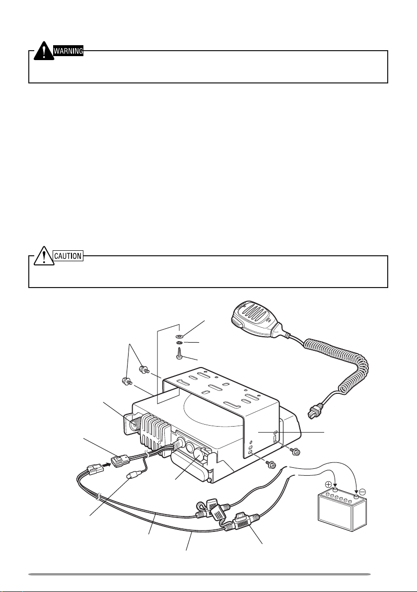
INSTALLING THE TRANSCEIVER
For passenger safety, install the transceiver securely using an optional mounting bracket and screw
set so the transceiver will not break loose in the event of a collision.
1 Mark the position of the holes in the dash by using the mounting bracket as a
template. Drill the holes, then attach the mounting bracket using self-tapping
screws.
• Be sure to mount the transceiver in a location where the controls are within easy
reach of the user and where there is sufficient space at the rear of the transceiver for
cable connections.
2 Connect the antenna and power cable to the transceiver.
3 Slide the transceiver into the mounting bracket and secure it using
hex-headed screws.
4 Mount an optional microphone hanger in a location where it will be within easy
reach of the user.
• The optional microphone and microphone cable should be mounted in a location
where it will not interfere with the safe operation of the vehicle.
When replacing the fuse in the DC power cable, be sure to replace it with a fuse of the same value.
Never replace a fuse with a fuse that has a higher value.
Antenna
connector
Power input
connector
DC power
cable
Ignition
sense cable
Hex-headed
screws
speaker jack
Black (–) cable
Flat washer
External
Red (+) cable
Spring washer
Self-tapping screw
Fuse
Optioinal
microphone
Mounting
bracket
12 V vehicle
battery
3
Page 10
GETTING ACQUAINTED
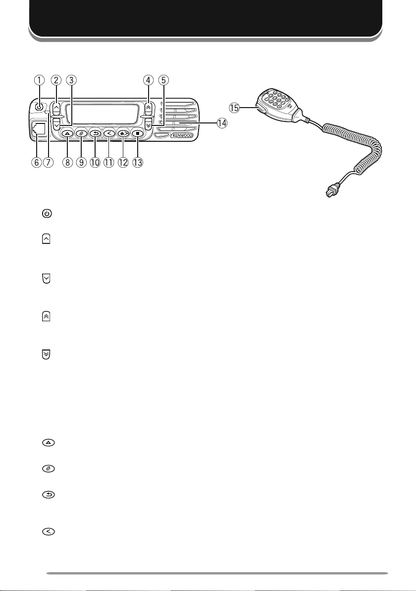
FRONT PANEL
Optional
microphone
a (power) switch
Press and hold to switch the transceiver power ON and OFF.
b key
Press to activate its programmable function {page 6}. The default is Volume
Up.
c key
Press to activate its programmable function {page 6}. The default is Volume
Down.
d key
Press to activate its programmable function {page 6}. The default is Channel/
Group ID Up.
e key
Press to activate its programmable function {page 6}. The default is Channel/
Group ID Down.
f Microphone jack
Insert the microphone plug into this jack.
g LED indicator
Lights red while transmitting and green while receiving a call.
h key
Press to activate its programmable function {page 6}.
i key
Press to activate its programmable function {page 6}. The default is Menu.
j key
Press to activate its programmable function {page 6}. The default is Squelch
Off Momentary.
k key
Press to activate its programmable function {page 6}. The default is Zone
Down.
4
Page 11
l
key
Press to activate its programmable function {page 6}. The default is Zone Up.
key
m
Press to activate its programmable function {page 6}.
n Speaker
Internal speaker
o PTT (Push-to-Talk) switch
Press and hold this switch, then speak into the microphone to call a station.
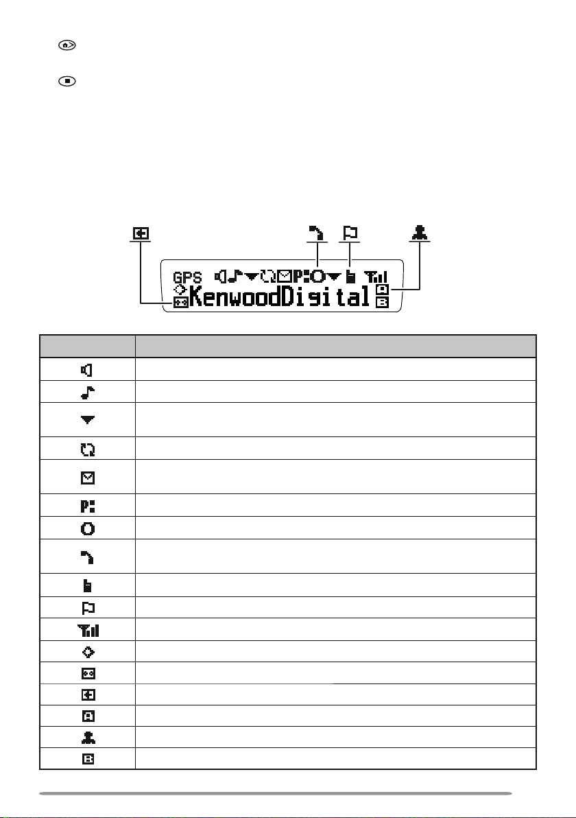
DISPLAY
Indicator Description
Monitor or Squelch Off is activated.
Blinks when an incoming call matches your Optional Signaling.
The current zone (left icon) or CH/GID (right icon) is added to
scan.
Scan is in progress. Blinks while scan is paused.
A message is stored in memory. Blinks when a new message
has arrived.
The current channel is a Priority channel.
Operator Selectable Tone (OST) is activated.
Appears when the selected group is programmed as telephone
IDs. Blinks during Auto Telephone search.
Talk Around is activated.
Site Lock is activated.
Signal strength indicator {page 20}.
Scrambler/ Encryption is activated.
Auto Recording on the VGS-1 option is activated.
Auto Reply Message is activated.
The AUX A function is activated.
Lone Worker is activated.
The AUX B function is activated.
5
Page 12

PROGRAMMABLE FUNCTIONS
Following is a list of available programmable functions. Contact your dealer for
details on those functions which have been programmed on your transceiver.
• 2-tone
• Auto Reply Message
• Auto Telephone
• Autodial
• Autodial Programming
• AUX A
• AUX B
• Broadcast
• Call 1 ~ 6
• CH/GID Down
• Channel Entry
• CH/GID Up
• CH/GID Recall
• Clock
• Clock Adjustment
• CW Message
• Direct CH/GID 1 ~ 5
• Direct CH/GID Select 1 ~ 5
• Display Format
• Emergency
• Fixed Volume
• Forced Search
• Function
• GPS Position Display
• Group (NXDN)
• Group + SDM (NXDN)
• Group + Status (NXDN)
• Home CH/GID
• Home CH/GID Select
• Horn Alert
• Individual (NXDN)
• Individual + SDM (NXDN)
• Individual + Status (NXDN)
• LCD Brightness
• Lone Worker
1
Available only for Analog Conventional operation
2
Available only if the VGS-1 optional board has been installed.
3
Available only for Analog Trunking operation.
4
Available only for Analog Conventional and Analog Trunking operation.
5
Available only for NXDN Trunking operation.
6
Available only for NXDN Conventional operation.
7
Emergency can be programmed only on the key and an optional auxiliary switch, such as an
8
Available only for NXDN Conventional and NXDN Trunking operation.
9
Available only for Analog Conventional, Analog Trunking, and NXDN Conventional operation.
10
Available only for Analog Conventional and NXDN Conventional operation.
6
1
3
5
6
7
5
6
emergency foot switch.
2
• Maintenance
• Menu
• Monitor
• Monitor Momentary
• OST (Operator Selectable Tone)
• Playback
• Priority-channel Select
9
9
2
10
1
• Public Address
• Scan
• Scan Delete/Add
• Scrambler/Encryption
• Scrambler/Encryption Code
• SDM (FleetSync/ NXDN)
• Selcall (FleetSync)
4
• Selcall + SDM (FleetSync)
• Selcall + Status (FleetSync)
• Send the GPS data
• Site Down
• Site Lock
• Site Up
• Squelch Level
• Squelch Off
5
5
5
1
1
• Squelch Off Momentary
8
4
4
1
• Stack
8
8
8
8
8
• Status (FleetSync/ NXDN)
• Talk Around
• Telephone Disconnect
• Transceiver Password
• Voice Memo
9
3
2
• Volume Down
• Volume Up
• Zone Delete/Add
• Zone Down
• Zone Up
Page 13

BASIC OPERATIONS
SWITCHING POWER ON/OFF
Press and hold the switch for approximately 1 second to turn the transceiver
power ON. Press and hold the switch again to turn the transceiver OFF.
■ Transceiver Password
If the transceiver is password protected, “PASSWORD” will appear on the
display when the power is turned ON. To unlock the transceiver, enter the
password:
1 Select a character using / .
• If you are using a microphone keypad, you can enter the password direclty.
2 Press to enter the selected character.
• This step is unnecessary when using the keypad.
3 Repeat steps 1 and 2 to enter the entire password.
• Press or # to delete a character. Press and hold or # to delete all
characters.
4 Press or to confirm the entry.
• If you enter an incorrect password, an error tone sounds and the transceiver
remains locked.
• The password can contain a maximum of 6 digits.
ADJUSTING THE VOLUME
Press the keys programmed as Volume Up/ Volume Down to adjust the volume.
SELECTING A ZONE AND CHANNEL/GROUP ID
Select the desired zone using / (default). Each zone contains a group of
channels.
Select the desired channel/group ID using / (default). Each channel/group ID
is programmed with settings for transmitting and receiving.
• You can toggle the display between the zone and channel/group ID names and number
by pressing the key programmed as Display Format, or by accessing the Menu {page 9}.
Note: If the default settings for / and / have been changed, use the appropriate keys to
select the zone and channel/group ID.
TRANSMITTING
1 Select the desired zone and channel/group ID.
2 Press the key programmed as [Monitor] or [Squelch Off] to check whether or
not the channel is free.
• If the channel is busy, wait until it becomes free.
7
Page 14

3 Press the PTT switch and speak into the microphone. Release the PTT switch
to receive.
• For best sound quality, hold the microphone approximately 1.5 inches (3 ~ 4 cm)
from your mouth.
■ Making Group Calls (Digital)
If a key has been programmed with [Group] or [Group + Status], you can
select a group ID from the list to make a call to those parties. To select a
group ID:
1 Press the key programmed as [Group] or [Group + Status].
2 Press / to select a group ID/name from the list.
3 Press and hold the PTT switch to make the call.
• Speak into the microphone as you would during a normal transmission.
■ Making Individual Calls (Digital)
If a key has been programmed with [Individual] or [Individual + Status], you
can make calls to specific persons.
1 Press the key programmed as [Individual] or [Individual + Status].
2 Press
3 Press and hold the PTT switch to make the call.
the / keys
• If you are using a microphone keypad, you can enter a unit ID directly.
• Speak into the microphone as you would during a normal transmission.
to select a unit ID from the list.
RECEIVING
Select the desired zone and channel. If signaling has been programmed on the
selected channel, you will hear a call only if the received signal matches your
transceiver settings.
Note: Signaling allows your transceiver to code your calls. This will prevent you from listening to
unwanted calls. Refer to “SIGNALING” on page 18 for details.
■ Receiving Group Calls (Digital)
When you receive a group call on a Conventional channel and the received group
ID matches the ID set up on your transceiver, you can hear the caller’s voice.
When on a Trunking channel, if the Group ID of a received call matches your
Group ID, you will hear the call.
■ Receiving Individual Calls (Digital)
When you receive an individual call on a Conventional channel, a ringing tone
will sound and the caller’s ID will appear on the display. To respond to the
call, press and hold the PTT switch and speak into the microphone as you
would during a normal transmission.
8
Page 15
MENU MODE
Many functions on this transceiver are selected or configured through the Menu
instead of physical controls. Once you become familiar with the Menu system,
you will appreciate the versatility it offers.
MENU ACCESS
1 Press the key programmed as [Menu].
2 Press / to select a Menu item.
• If you are using a microphone keypad, you can enter a Menu number directly.
3 Press to set up the selected Menu item.
4 Press / to select your desired setting.
• For settings with more than 1 level, repeat steps 3 and 4.
5 Press to set the selected setting and exit Menu mode.
• Press at any time to return to the previous display.
• Press
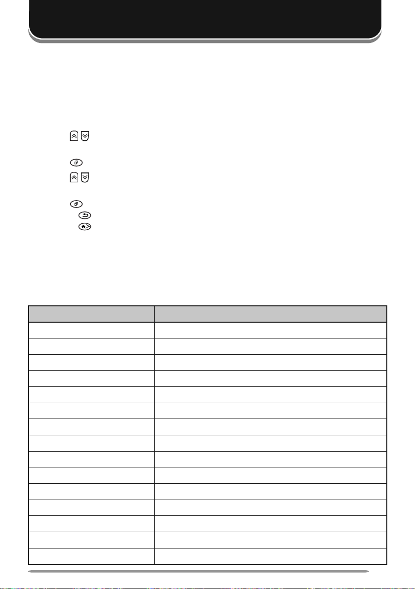
MENU CONFIGURATION
Some transceiver keys may already be programmed with functions listed in the
Menu. Those functions can be accessed directly by pressing the key. All other
functions can still be accessed using the transceiver Menu. The following table
lists the available Menu items.
2-TONE 2-tone Mode
AUTO REPLY MSG Auto Reply Message ON/OFF
AUTO TELEPHONE Auto Telephone
AUTO DIAL Autodial Mode
AUTO DIAL PROG Autodial Programming Mode
AUX A AUX A ON/OFF
AUX B AUX B ON/OFF
BROADCAST Broadcast ON/OFF
CLOCK Clock ON/OFF
CLOCK ADJUST Clock Adjustment mode
DIRECT CH1 SEL Direct CH/GID 1 ~ 5 Select
DISP FORMAT Display Format ON/OFF
EXT MIC TYPE External Microphone Type mo
FIXED VOLUME Fixed Volume
FORCED SEARCH Forced Search
at any time to exit Menu mode.
Menu Description
9
Page 16

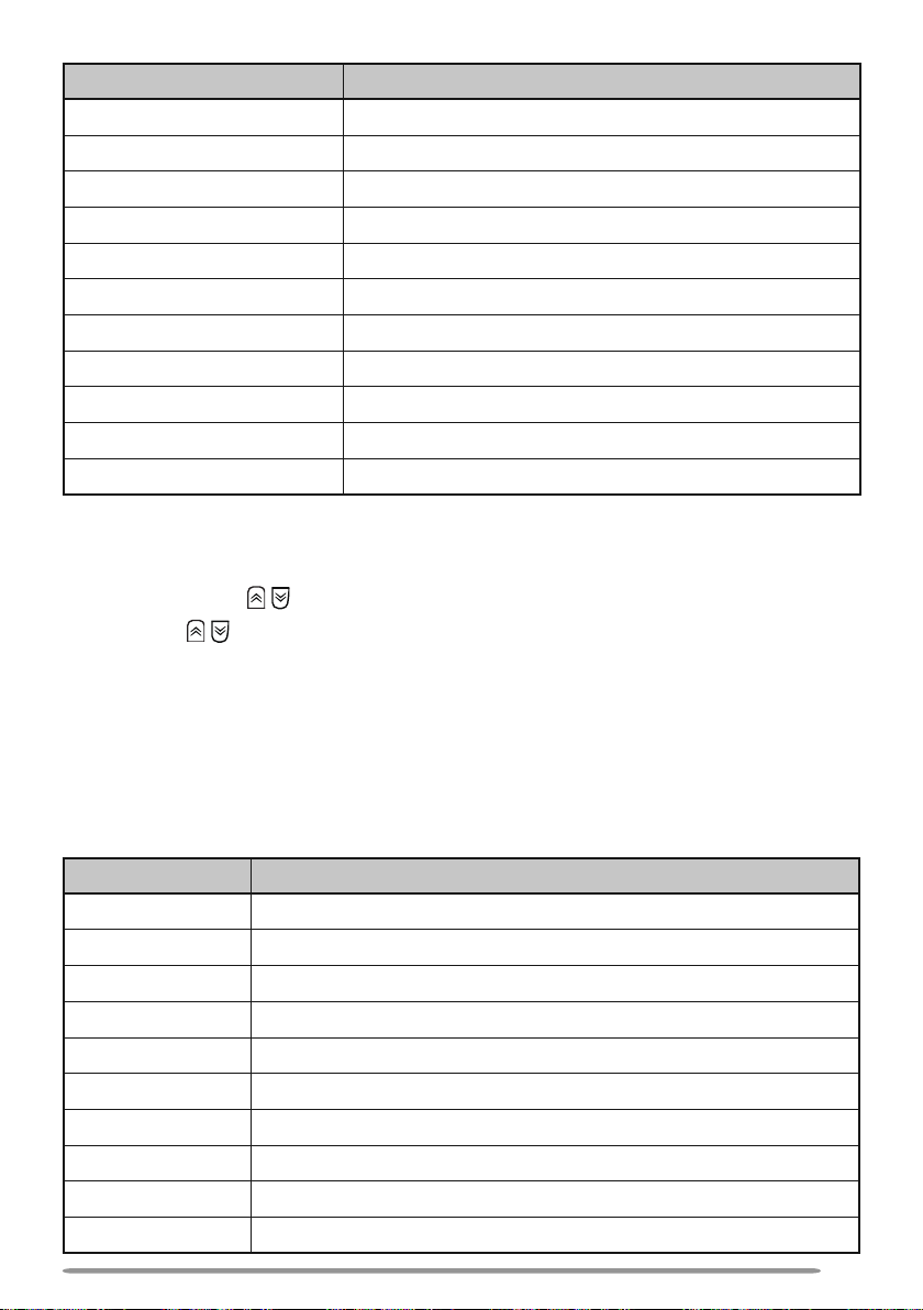
Menu Description
GPS POS DISP GPS Position Display mode
GROUP Group mode
GROUP+STATUS Group + Status mode
GROUP+SDM Group + SDM mode
HOME CH SEL Home CH/GID Select
HORN ALERT Horn Alert ON/OFF
INDIVIDUAL Individual mode
INDIV+STATUS Individual + Status mode
INDIV+SDM Individual + SDM mode
LCD BRIGHTNESS LCD Brightness level
LONE WORKER Lone Worker ON/OFF
MAINTENANCE Maintenance Display Mode
MONITOR Monitor ON/OFF
OST OST ON/OFF
OST LIST OST mode
PLAYBACK Playback mode
PRI CH SEL Priority Channel Select mode
RX AUDIO EQ RX Audio Equalizer mode
RX AGC RX Audio Gain Control mode
RX LOW CUT RX Low Cut mode
PUBLIC ADDRESS Public Address System ON/OFF
SCAN Scan ON/OFF
SCAN DEL/ADD Scan Delete/Add
SCRAM/ENCRYP Scrambler/Encryption ON/OFF
SCRAM CODE Scrambler/Encryption Code mode
SELCALL Selcall mode
SELCALL+STATUS Selcall + Status mode
SELCALL+SDM Selcall + SDM mode
SEND GPS DATA Transmit your GPS data
SITE LOCK Site Lock ON/OFF
SITE No. Display Site Number
SQUELCH LEVEL Squelch Level mode
10
Page 17
Menu Description
SQUELCH OFF Squelch Off ON/OFF
STACK Stack mode
STATUS Status mode
SHORT MESSAGE Short Message mode
TALK AROUND Talk Around ON/OFF
TX AUDIO EQ TX Audio Equalizer mode
TX AGC TX Audio Gain Control mode
TX NOISE SUPPR TX Noise Suppressor mode
PASSWORD Transceiver Password mode
VOICE MEMO Voice Memo mode
ZONE DEL/ADD Zone Delete/Add
CHARACTER ENTRY
There are 2 methods available for entering characters:
1) Pressing the / keys
Press / to cycle the characters from A ~ Z, 0 ~ 9, and a space (default
settings).
You can also assign a character to an optional key and later press that
key to recall the assigned character: A ~ Z, a ~ z, 0 ~ 9, or a space and
characters.
2) Using the microphone keypad
Press the microphone keys to enter characters as shown in the table
below:
DTMF Key Character Cycle
11
2 A B C 2
3 D E F 3
4 G H I 4
5 J K L 5
6 M N O 6
7 P Q R S 7
8 T U V 8
9 W X Y Z 9
0 [space] 0
11
Page 18

SCAN
Scan monitors for signals on the transceiver channels. While scanning, the
transceiver checks for a signal on each channel and only stops if a signal is
present.
To begin scanning, press the key programmed as [Scan].
• The icon appears on the display.
• When a signal is detected on a channel, Scan pauses at that channel. The transceiver
will remain on the busy channel until the signal is no longer present, at which time Scan
resumes.
To stop scanning, press the [Scan] key again.
Note: To use Scan, there must be at least 2 channels in the scan sequence.
TEMPORARY CHANNEL LOCKOUT
During scan, you can temporarily remove specific channels from the scanning
sequence by selecting them and pressing the key programmed as [Scan Delete/
Add].
• The channel is no longer scanned. However, when scanning is ended and restarted, the
channels are reset and deleted channels will again be in the scanning sequence.
PRIORITY SCAN
Note: To use Priority Scan, a Priority channel must be programmed.
When using a single Priority channel, the transceiver will automatically change to
the Priority channel when a call is received on that channel, even if a call is being
received on a normal channel.
When using dual Priority channels, Priority channel 1 is given precedence over
Priority channel 2. So, if a call is received on Priority channel 1 while a call is
already on Priority channel 2, the transceiver will change to Priority channel 1.
SCAN REVERT
The Scan Revert channel is the channel selected when you press the PTT switch
to transmit during scan. Your dealer can program one of the following Scan
Revert channels:
• Selected: The last channel selected before scan.
• Selected + Talkback: Same as “Selected”, plus you can respond to calls on
the channel at which scan is paused.
• Priority 1/ Priority 2: The Priority channel (either Priority 1 or Priority 2).
• Priority 1 + Talkback/ Priority2 + Talkback: Same as “Priority 1/ Priority 2”,
plus you can respond to calls on the channel at which scan is paused.
• Last Called + Selected: The last channel on which you receive a call.
12
Page 19

SCAN DELETE/ADD
You can add and remove zones and/or channels/group IDs to and from your scan
list.
1 Select your desired zone and/or channel/group ID.
2 Press the key programmed as [Zone Delete/Add] (to add/remove zones) or
[Scan Delete/Add] (to add/remove channels/group IDs).
• You can also press and hold the key programmed as [Scan Delete/Add] to add/
remove zones.
PRIORITY-CHANNEL SELECT
If the Priority channel has been set as Operator Selectable by your dealer, you
can reprogram the Priority channels.
1 Select your desired zone and channel/group ID.
2 Press the key programmed as [Priority-channel Select].
3 Press / to select “NORMAL”, “PRIORITY 1” ( ), “PRIORITY 2” ( ), or
“PRIORITY 1&2” ( ).
4 Press to save the setting and exit.
13
Page 20

FleetSync: ALPHANUMERIC 2-WAY PAGING
FleetSync is an Alphanumeric 2-way Paging Function, and is a protocol owned by
JVC KENWOOD Corporation.
Note: This function is available only in analog operation.
SELCALL (SELECTIVE CALLING)
A Selcall is a voice call to a station or group of stations.
■ Transmitting
1 Select your desired zone and channel.
2
Press the key programmed as [Selcall] or [Selcall + Status] to enter Selcall
mode.
3 Press / to select the station you want to call.
• If you are using a microphone keypad and Manual Dialing is enabled, you can
directly enter the station ID.
4 Press the PTT switch and begin your conversation.
■ Receiving
An alert tone will sound and the transceiver will enter Selcall Mode. The
calling station’s ID will appear when a Selcall is received. You can respond to
the call by pressing the PTT switch and speaking into the microphone.
■ Identification Codes
An ID code is a combination of a 3-digit Fleet number and a 4-digit ID number.
Each transceiver has its own ID.
• Enter a Fleet number (100 ~ 349) to make a fleet call.
• Enter an ID number (1000 ~ 4999) to make an individual call in your fleet.
• Enter a Group ID (which is programmed in the FPU) to make a group call.
• Enter a Fleet number followed by an ID number to make an individual call in your
desired fleet (Inter-fleet call).
• Select “ALL” Fleet and enter an ID number to make a call to the selected ID in all
fleets (Supervisor call).
• Select “ALL” Fleet and “ALL” ID to make a call to all units (Broadcast call).
STATUS MESSAGE
You can send and receive 2-digit Status messages which may be decided in your
talk group. Messages can contain up to 16 alphanumeric characters. Status
messages range from 10 to 99 (80 ~ 99 are reserved for special messages).
A maximum of 15 received messages (combined status messages and short
messages) can be stored in the stack memory of your transceiver.
■ Transmitting
1 Select your desired zone and channel.
2 Press the key programmed as [Status] to enter Status mode (proceed to
14
Page 21

step 5) or [Selcall + Status] to enter Selcall mode (proceed to step 3).
3 Press / to select the station you want to call.
• If Manual Dialing is enabled, you can enter the station ID by using the
microphone keypad, or by using
to select a digit, then press
Repeat this process until the entire ID is entered.
/ . When using / , cycle through the digits
to set the digit and move the cursor to the right.
4 Press to enter Status mode.
5 Press / to select the status you want to transmit.
• If Manual Dialing is enabled, you can enter the status ID by using the
microphone keypad, or by using
/ (refer to step 3, above).
6 Press the PTT switch or to initiate the call.
• “<<COMPLETE>>” appears on the display when the status has been
successfully transmitted.
■ Receiving
The icon will flash and a calling ID or text message will appear when a
Status call is received. Press any key to return to normal operation.
■ Reviewing Messages in the Stack Memory
1 Press the key programmed as [Stack], or press and hold the key
programmed as [Selcall], [Status], or [Selcall + Status] to enter Stack
mode.
• The last received message is displayed.
2 Press / to select the desired message.
• Message types are identified as follows:
I: Caller ID, S: Status Message, M: Short Message
• Press and hold
ID Name > Status/Short Message > CH/GID > Time Stamp
3 Press to return to normal operation.
• To delete the selected message, press or #. To confirm the deletion, press
or .
• To delete all messages, press and hold
deletion, press
for 1 second to cycle the display information as follows:
or # for 1 second. To confirm the
or .
SHORT/LONG MESSAGES
Received short messages are displayed the same as Status messages and are
stored in the same stack memory.
To send short messages, and to send and receive long messages, you must
connect the transceiver to a PC. Ask your dealer for details.
GPS REPORT
To send your location data, you must first connect a GPS unit to the transceiver.
GPS data can be manually transmitted by pressing the key programmed as [Send
the GPS data], or by accessing the Menu {page 9}. If set up by your dealer, GPS
data may be automatically transmitted at a preset time interval.
15
Page 22

ADVANCED OPERATIONS
DTMF (DUAL TONE MULTI FREQUENCY) CALLS
■ Making a DTMF Call
Note: DTMF calls can be made only in analog operation.
Manual Dialing
1 Press and hold the PTT switch.
2 Enter the desired digits using the microphone keypad.
• If you release the PTT switch, transmit mode will end even if the complete
number has not been sent.
• If the Keypad Auto PTT function has been enabled by your dealer, you do
not need to press the PTT switch to transmit; you can make the call simply by
pressing the microphone keys.
Store & Send
1 Press the key programmed as [Autodial].
2 Enter up to 30 digits using the microphone keypad.
• Alternatively, you can enter digits by using / {page 11}.
3 Press the PTT switch or to make the call.
■ Autodial
Autodial allows you to quickly call DTMF numbers that have been programmed
onto your transceiver.
1 Press the key programmed as [Autodial], or access the Menu {page 9}.
• The first entry in the Autodial list appears on the display.
2 Press / to select your desired Autodial list number, or enter the list
number directly (01 ~ 32) .
• The stored entry appears on the display.
3 Press the PTT switch to make the call.
■ Stun Code
This function is used when a transceiver is stolen or lost. When the transceiver
receives a call containing a stun code, the transceiver becomes disabled. The
stun code is cancelled when the transceiver receives a call with a revive code.
16
Page 23

TELEPHONE CALLS
■ Making a Telephone Call
Manual Dialing (Analog)
1 Select your desired zone and telephone group ID.
2 Press the PTT switch to start the call.
3 Enter your desired digits using the microphone keypad.
Selecting a Number from the List
1 Select your desired zone and telephone group ID.
2 Press the key programmed as [Autodial].
• The last called unit appears on the display.
3 Press / to select your desired list number.
4 Press the PTT switch to start the call.
■ Receiving a Telephone Call
When a call is received, press and hold the PTT switch to speak, and release
it to receive.
• Only one person can speak at a time.
EMERGENCY CALLS
If your transceiver has been programmed with the Emergency function, you can
make emergency calls.
1 Press and hold the key programmed as [Emergency].
• Ask your dealer for the length of time necessary to hold this key before the
transceiver enters Emergency mode.
• When the transceiver enters Emergency mode, it will change to the Emergency
channel and begin transmitting based on how it is set up by your dealer.
2 To exit Emergency mode, press and hold the [Emergency] key again.
• If the Emergency mode completes a preset number of cycles, Emergency mode will
automatically end and the transceiver will return to the zone and channel that was in
use before Emergency mode was entered.
Note:
◆ Your dealer can set the transceiver to emit a tone when transmitting in Emergency mode.
◆ Your dealer can set the transceiver to emit tones and received signals as normal, or mute the
speaker during Emergency operation.
17
Page 24

SCRAMBLER
Press the key programmed as [Scrambler/ Encryption], or access the Menu
{page 9}, to switch the transceiver to secure (encrypted) transmission.
• Pressing the microphone PTT switch after the Scrambler function has been turned ON
encrypts the transmitted signal.
SIGNALING
■ Quiet Talk (QT)/ Digital Quiet Talk (DQT)
Your dealer may have programmed QT or DQT signaling on your transceiver
channels. A QT tone/ DQT code is a sub-audible tone/code which allows you
to ignore (not hear) calls from other parties who are using the same channel.
Operator Selectable Tone (OST)
If a key has been programmed with OST, you can reprogram the QT/DQT
settings on each of your channels.
1 Select your desired channel.
2 Press and hold the key programmed as OST for 1 second.
3 Press / to select your desired tone or code.
• Your dealer can set up to 40 tones/codes.
4 Press to save your new setting.
5 When you have finished operating using OST, press the OST key again to
turn the OST function OFF.
■ Radio Access Number (RAN)
RAN is a new signaling system designed for digital radio communications.
When a channel is set up with a RAN, squelch will only open when a call
containing a matching RAN is received. If a call containing a different RAN
is made on the same channel you are using, you will not hear the call. This
allows you to ignore (not hear) calls from other parties who are using the same
channel.
■ Optional Signaling
Your dealer may also program several types of option signaling for your
transceiver channels.
2-tone Signaling: 2-tone Signaling opens the squelch only when your
transceiver receives a call containing matching 2 tones.
DTMF Signaling: DTMF Signaling opens the squelch only when the
transceiver receives a call containing a matching DTMF code.
FleetSync Signaling: Refer to “SELCALL (SELECTIVE CALLING)” on page 14.
NXDN ID Signaling: NXDN ID is an optional signaling system available only
for digital communications.
18
Page 25

CLOCK
If activated by your dealer, you can view the clock any time by pressing the key
programmed as [Clock].
Note: Removing the transceiver power for extended periods will clear the clock time.
To set the time:
1 Press the key programmed as [Clock Adjustment].
• The current time setting appears.
2 Press / to increase or decrease the year setting.
3 Press to set the year and cycle to the month setting.
4 Repeat steps 2 and 3 to set the month, day, hour, and minute.
5 Press to exit Clock Adjustment mode.
• You can press at any time to exit Clock Adjustment mode.
LCD BRIGHTNESS
The LCD backlight can be turned off or set to low or high levels. To cycle through
the brightness settings, press the key programmed as [LCD Brightness].
• Each press of [LCD Brightness] cycles the brightness level from high to low to off, and
then back to high.
HORN ALERT
To use the Horn Alert function, your dealer must install an optional unit. When
a call is received that matches the optional signaling set up on your transceiver,
Horn Alert causes the vehicle horn or some other external alert to sound. This
function notifies you of a received call when you are away from your vehicle.
To toggle Horn Alert ON and OFF, press the key programmed as [Horn Alert] or
access the Menu {page 9}.
• HA momentarily appears on the display when Horn Alert is active.
PUBLIC ADDRESS (PA)
To use the Public Address system, your dealer must install an optional unit and
an external speaker. This function causes all audio input via the microphone to
be amplified and output through the external speaker.
To use the PA system:
1 Press the key programmed as [Public Address] or access the Menu {page 9}
• PA appears on the display when the PA system is active.
2 Press and hold the PTT switch, then speak into the microphone.
• Use the Volume Up and Volume Down keys to adjust the audio output from the
external speaker.
3 Press the [Public Address] key again or change the zone or channel/group
ID to return to normal operation.
19
Page 26

BACKGROUND OPERATIONS
Your dealer can activate a variety of transceiver functions to perform without any
additional operation on your part.
TIME-OUT TIMER (TOT)
The Time-out Timer is used to prevent you from using a channel for an extended
duration. If you continuously transmit for a preset time, the transceiver will stop
transmitting and an alert tone will sound. Release the microphone PTT switch.
SIGNAL STRENGTH INDICATOR
The signal strength indicator displays the strength of received calls.
Strong Sufficient Weak Very weak
No icon appears when no signal is available.
flashes when out of range (NXDN Trunking only).
COMPANDER
If programmed by your dealer for a channel, the compander will remove
excessive noise from transmitted signals, to provide higher clarity of signals.
BUSY CHANNEL LOCKOUT (BCL)
On Conventional channels, if BCL is set up by your dealer, you will be unable to
transmit if the channel is already in use. Use a different channel or wait until the
channel becomes free.
If BCL Override has been programmed, you can transmit over the current signal:
1 Press and hold the PTT switch.
• If the channel is already in use, a warning tone will sound.
2 Quickly release and then press the PTT switch again.
3 Speak into the microphone as you would during a normal call.
CONTROL CHANNEL HUNT
On digital Trunking channels, the transceiver automatically searches for a control
channel.
• While searching for a control channel, the antenna icon will flash and no signals can be
received.
PTT ID
PTT ID is the transceiver unique ID code which is sent each time the PTT switch
is pressed and/or released.
Note: PTT ID can be made only in analog operation.
20
Page 27

VGS-1 OPTIONAL VOICE GUIDE & STORAGE UNIT
VOICE RECORDER
The voice recorder allows you to record conversations and create voice memos.
■ Auto Recording
If activated, the auto recorder will continuously record all transmitted and
received signals. The recording storage area retains only the last 30 seconds
of recording.
■ Voice Memos
To record a voice memo for later playback:
1 Press the key programmed as [Voice Memo], press and hold the key
programmed as [Playback], or access the Menu {page 9}.
• The duration of recording memory will appear on the display and begin counting
down.
2 Speak into the microphone to record your memo.
3 Press to end the recording and store it in memory.
• If the memory becomes full, recording will stop and the voice memo will be
stored in memory.
■ Auto Reply Message
You can set the transceiver to automatically respond to Individual Calls while
using FleetSync/NXDN.
1 Press the key programmed as [Auto Reply Message] to enter Auto Reply
Message mode.
2 When you receive an Individual Call, the transceiver will send an automatic
response to the caller after 3 seconds, and “GREETING” appears on the
display.
• If you are available to receive the call, press any key to cancel the auto
response.
• If there is memory available on your transceiver for recording, “I am not available.
Leave your Message.” will be sent to the caller and they can leave a recorded
message. When a message is stored on your transceiver, “Msg Rcvd” appears
on the display.
• If no memory is available on your transceiver, “I am not available” will be sent to
the caller and “ MEMORY FULL” appears on the display.
21
Page 28

■ Playback
To play back a recorded conversation, memo, or message:
1 Press the key programmed as [Playback] or access the Menu {page 9}.
• If the last action on your transceiver was to auto record your conversation,
“STORE?” will appear on the display, otherwise a recording channel with the
time of the recording will appear.
2 Press / to select the channel you want to play.
• “AR” represents auto recorded conversations, “RM” represents auto reply
messages, and “VM” represents voice memos.
3 The transceiver will announce the time and channel, then the recording will
play back.
• When the entire recording has been played, “END OF MESSAGE” is displayed.
You can also end the recording at any time by pressing
• To delete the selected recording, press
and hold
.
. To clear all the recorded data, press
.
VOICE GUIDE
When changing the zone and/or channel, an audio voice will announce the new
zone and channel. Additionally, when changing a function setting, the new setting
will be announced.
Note: Voice announcements vary by dealer setting.
22
Page 29

NX-700H(T)
NX-800H(T)
VHF數位類比雙模無線電車裝台/
UHF數位類比雙模無線電車裝台
使用說明書
Page 30

Page 31

致謝
謝謝您惠購 KENWOOD 無線電車裝台。
本使用說明書僅涉及 NEXEDGE 無線電車裝台的基本操作。有關可能增加的自訂功能之資訊,請詢
問當地的經銷商。
使用者須知
◆ 政府法令禁止在政府管轄地區範圍內未經許可進行發射機的操作。
◆ 非法操作將受到罰款和/或拘留的處罰。
◆ 維修僅可由專業人員進行。
安全性:使用者應瞭解和認識使用無線電車裝台的一般危險性。
◆ 易爆環境 (氣體、粉塵及煙霧等)
在加油或者停車於加油站時,請關閉無線電車裝台。如果您的無線電車裝台安裝在汽
車的後行李廂部位,請不要在後行李廂中放置備用燃油箱。
◆ 射頻傳輸帶來的損傷
當有人位於天線附近或在觸摸天線時,請不要操作您的無線電車裝台,以免可能導致
的射頻灼傷或相關的身體傷害。
◆ 炸藥火帽
在炸藥火帽 150 米以內操作無線電車裝台可能導致炸藥爆炸。在發生爆炸或張貼有「
關閉雙向無線電」標誌的區域內,請關閉您的無線電車裝台。如果透過您的汽車運輸
火帽,確保將其裝在具有內部填充層的密封金屬箱內運輸。在將火帽放入或從包裝箱
中取出時,不要發射。
i
Page 32

注意事項
請遵守以下注意事項,防止發生火災、人身傷害或者損壞無線電車裝台。
• 請不要在駕車時嘗試設定無線電車裝台;否則會導致危險後果。
• 不論有任何理由都不可拆卸或改裝無線電車裝台。
• 請不要讓無線電車裝台受到長時間的陽光直射,也不要將它放在加熱器具附近。
• 如果發現從無線電車裝台發出異常氣味或者冒煙,應立即關閉無線電車裝台電源,並與當
地的 KENWOOD 經銷商聯繫。
• 駕車時使用無線電車裝台可能違反交通法規。請查看並遵守當地的交通法規。
• 請不要使用非 KENWOOD 指定的選配零件。
◆ 本無線電車裝台只能於 12 V 負極接地系統中使用!在將無線電車裝台安裝到車輛上之前,請先
檢查車輛上的電池極性和電壓。
◆ 只能使用 KENWOOD 選配的直流電源線。
◆ 不要剪下和/或拆下直流電流線上的保險絲座。
為了保護乘客安全,請使用選配的安裝支架和螺絲組牢固地安裝無線電車裝台,使無線電車裝台在
發生車輛碰撞時不會滑脫。
ii
Page 33

目錄
開箱和裝置檢查 ....................................................................................1
配備附件 ..................................................................................................... 1
準備工作 ...............................................................................................2
所需工具 ..................................................................................................... 2
連接電源線 .................................................................................................. 2
安裝無線電車裝台 ....................................................................................... 3
熟悉本機 ...............................................................................................4
前面板 ......................................................................................................... 4
顯示幕 ......................................................................................................... 5
可程式化預設功能 .................................................................................6
基本操作 ...............................................................................................7
開啟/關閉電源 ............................................................................................. 7
調整音量 ..................................................................................................... 7
選擇區間和頻道/群 ID.................................................................................. 7
發射 ............................................................................................................. 7
接收 ............................................................................................................. 8
選單模式 ...............................................................................................9
選單存取 ..................................................................................................... 9
選單設定 ..................................................................................................... 9
字元輸入 ................................................................................................... 11
掃描 ....................................................................................................12
頻道暫時鎖定 ............................................................................................ 12
優先掃描 ................................................................................................... 12
主掃描 ....................................................................................................... 12
掃描刪除/新增 ........................................................................................... 13
優先頻道選擇 ............................................................................................ 13
FleetSync:字母數字雙路調度功能 ....................................................14
選呼 (選擇呼叫) ......................................................................................... 14
狀態訊息 ................................................................................................... 14
短訊息/長訊息 ........................................................................................... 15
GPS 報告 .................................................................................................. 15
iii
Page 34

進階操作 .............................................................................................16
DTMF (雙音多頻) 呼叫 .............................................................................. 16
電話呼叫 ................................................................................................... 17
緊急呼叫 ................................................................................................... 17
加密 ........................................................................................................... 18
信號 ........................................................................................................... 18
時鐘 ........................................................................................................... 19
LCD 亮度 .................................................................................................. 19
喇叭提示 ................................................................................................... 19
車外擴音 (PA) ........................................................................................... 19
後台操作 .............................................................................................20
發射逾時計時器 (TOT) .............................................................................. 20
信號強度指示器 ......................................................................................... 20
壓縮擴展器 ................................................................................................ 20
使用中頻道鎖定 (BCL) .............................................................................. 20
控制頻道搜尋 ............................................................................................ 20
PTT ID ...................................................................................................... 20
VGS-1 選配的語音導航和存儲裝置 .....................................................21
語音錄製 ................................................................................................... 21
語音導航 ................................................................................................... 22
iv
Page 35

開箱和裝置檢查
注:下列開箱說明針對 KENWOOD 經銷商、經授權的 KENWOOD 服務機構或者工廠。
請小心從包裝箱中取出無線電車裝台。我們建議您在丟棄包裝材料之前,請按照如
下清單清點附件。如果發現任何物品在運輸中丟失或損壞,請立即向送貨人提交索
賠書。
配備附件
• 直流電源線 .................................................................................................................. 1
• 保險絲 (15 A) ......................................................................................................... 2
• 安裝支架 ...................................................................................................................... 1
• 螺絲組
• 5 x 16 mm 自攻螺絲 .............................................................................................. 4
• 六角螺絲及墊片 .................................................................................................... 4
• 彈簧墊圈 ................................................................................................................ 4
• 平面墊片 ................................................................................................................ 4
• 使用說明書 .................................................................................................................. 1
1
Page 36

準備工作
如果在進行發射時,未對車輛中的各種電子設備採取適當的射頻能量保護,則可能導致這些設備損
壞。電子燃油加注器、防滑制動器和導航控制系統是一般可能損壞的設備。如果您的車輛配有這些
設備,請諮詢車輛經銷商並請他們確定是否需要在發射時對這些設備進行保護。
注:下列準備工作的說明針對 KENWOOD 經銷商、經授權的 KENWOOD 服務機構或者工廠。
所需工具
注:在安裝無線電車裝台之前,請一定要檢查安裝螺絲探出安裝面之下的長度。鑽孔時,小心不要
損壞車輛接線或部件。
安裝無線電車裝台時需要如下工具:
• 6 mm 或更大尺寸的電鑽
• 用於安裝選配支架的自攻螺絲所用的 4.2 mm 鑽頭
• 圓形切割器
連接電源線
◆ 本無線電車裝台只能於 12 V 負極接地系統中使用!在將無線電車裝台安裝到車輛上之前,請先
檢查車輛上的電池極性和電壓。
◆ 只能使用 KENWOOD 選配的直流電源線。
◆ 不要剪下和/或拆下直流電流線上的保險絲座。
1 檢查是否有現存孔洞可使電源線穿過,它一般位於防火牆中。若無孔洞,請使
用圓形切割器鑽進防火牆,然後安裝橡膠孔環。
2 將兩根電源線導線穿過防火牆並進入發動機艙 (從乘客艙)。
3 將紅色導線連接至電池正極 (+),將黑色導線連接至電池負極 (–)。
• 使保險絲盡可能靠近電池。
4 用束帶將多餘的電纜盤起並固定好。
• 請務必保持電纜足夠鬆弛,以便在取下無線電車裝台進行維修時可保持供電。
2
Page 37

安裝無線電車裝台
為了保護乘客安全,請使用選配的安裝支架和螺絲組牢固地安裝無線電車裝台,使無線電車裝台在
發生車輛碰撞時不會滑脫。
1 以安裝支架為樣板,標記儀表盤中孔洞的位置。鑽孔,然後使用自攻螺絲將安
裝支架安裝好。
• 請務必將無線電車裝台安裝於方便使用者操作的地方,且無線電車裝台後部應留有足
夠的空間用於電纜連接。
2 將天線和電源線連接至無線電車裝台。
3 將無線電車裝台滑入安裝支架,並用六角螺絲將其固定。
4 在方便使用者操作的地方安裝選配的麥克風架。
• 選配的麥克風和麥克風電纜應安裝於不會影響車輛安全操作的地方。
更換直流電源線上的保險絲時,請務必更換為相同額定值的保險絲。切勿更換為額定值更大的保險
絲。
平面墊片
六角螺絲
彈簧墊圈
自攻螺絲
選配的麥克風
天線接頭
電源輸入接頭
直流電源線
點火感測電纜
外部揚聲器插孔
黑色 (–) 電纜
紅色 (+) 電纜
安裝支架
12 V 車用電池
保險絲
3
Page 38

熟悉本機
前面板
(電源) 開關
a
按下並按住可開啟和關閉無線電車裝台電源。
b 鍵
按下該鍵開啟可程式化預設功能 {第 6 頁}。預設為「音量高」。
c 鍵
按下該鍵開啟可程式化預設功能 {第 6 頁}。預設為「音量低」。
d 鍵
按下該鍵開啟可程式化預設功能 {第 6 頁}。預設為「頻道/群 ID 增」。
e 鍵
按下該鍵開啟可程式化預設功能 {第 6 頁}。預設為「頻道/群 ID 減」。
f 麥克風插孔
將麥克風插頭插入此插孔。
g LED 指示燈
發射時發紅光,接收呼叫時發綠光。
h 鍵
按下該鍵開啟可程式化預設功能 {第 6 頁}。
i 鍵
按下該鍵開啟可程式化預設功能 {第 6 頁}。預設為「選單」。
j 鍵
按下該鍵開啟可程式化預設功能 {第 6 頁}。預設為「暫態靜噪取消」。
k 鍵
按下該鍵開啟可程式化預設功能 {第 6 頁}。預設為「區間減」。
選配的麥克風
4
Page 39

l
鍵
按下該鍵開啟可程式化預設功能 {第 6 頁}。預設為「區間增」。
鍵
m
按下該鍵開啟可程式化預設功能 {第 6 頁}。
n 揚聲器
內部揚聲器
o PTT (按下通話) 開關
按下並按住後對著麥克風講話來呼叫對方電臺。
顯示幕
指示燈 說明
啟動監聽或靜噪取消。
收到的呼叫與可選信號相符時閃爍。
目前區間 (左側圖示) 或頻道/群 ID (右側圖示) 被加至掃描清單。
掃描進行中。暫停掃描時閃爍。
記憶體中存有訊息。接收到新訊息時閃爍。
目前頻道為優先頻道。
啟動使用者可選音調 (OST)。
所選群體設定為電話 ID 時出現。執行自動電話搜尋時閃爍。
啟動離網通信。
啟動站台鎖定。
信號強度指示器 {第 20 頁}。
啟動加密。
啟動 VGS-1 選配件上的自動錄音功能。
啟動自動回覆訊息功能。
啟動 AUX A 功能。
啟動單獨工作者模式。
啟動 AUX B 功能。
5
Page 40

可程式化預設功能
以下為可用的可程式化預設功能之清單。有關在無線電車裝台上設定的這些功能的
詳細情況,請與當地的經銷商聯繫。
• 2-音
• 自動回覆訊息
• 自動電話
• 自動撥號
• 自動撥號設定
• AUX A
• AUX B
• 廣播
• 呼叫 1 ~ 6
• 頻道/群 ID 減
• 頻道輸入
• 頻道/群 ID 增
• 頻道/群 ID 再呼叫
• 時鐘
• 時鐘調整
• CW 訊息
• 直通頻道/群 ID 1 ~ 5
• 直通頻道/群 ID 選擇 1 ~ 5
• 顯示格式
• 緊急
• 固定音量
• 強制搜尋
• 功能
• GPS 位置顯示
• 群呼 (NXDN)
• 群呼 + SDM (NXDN)
• 群呼 + 狀態 (NXDN)
• 歸屬頻道/群 ID
• 歸屬頻道/群 ID 選擇
• 喇叭提示
• 個呼 (NXDN)
• 個呼 + SDM (NXDN)
• 個呼 + 狀態 (NXDN)
• LCD 亮度
• 單獨工作者
1
2
3
4
5
6
7
8
9
10
6
1
2
3
5
• 維護
• 選單
• 監聽
• 暫態監聽
• OST (使用者可選音調)
• 重播
• 優先頻道選擇
9
9
2
10
• 車外擴音
• 掃描
• 掃描刪除/新增
• 加密
• 加密代碼
• SDM (FleetSync/NXDN)
• 選呼 (FleetSync)
6
• 選呼 + SDM (FleetSync)
• 選呼 + 狀態 (FleetSync)
• 發送 GPS 數據
• 站台減
7
5
• 站台鎖定
• 站台增
• 靜噪位準
• 靜噪取消
• 暫態靜噪取消
6
8
8
• 堆疊
• 狀態 (FleetSync/ NXDN)
• 離網通信
• 電話掛斷
• 無線電車裝台密碼
• 語音備忘
8
8
8
• 音量低
• 音量高
• 區間刪除/新增
• 區間減
8
4
5
5
5
1
1
1
9
3
2
• 區間增
僅對類比常規操作可用。
僅在安裝 VGS-1 選配板的情況下可用。
僅對類比中繼操作可用。
僅對類比常規及類比中繼操作可用。
僅對 NXDN 中繼操作可用。
僅對 NXDN 常規操作可用。
緊急功能僅可設定於 鍵及選配的輔助開關之上,如緊急腳踏開關。
僅對 NXDN 常規及 NXDN 中繼操作可用。
僅對類比常規、類比中繼及 NXDN 常規操作可用。
僅對類比常規及 NXDN 常規操作可用。
1
4
4
Page 41

基本操作
開啟/關閉電源
按下並按住 開關約 1 秒,可開啟無線電車裝台電源。再次按下並按住 開關則
關閉無線電車裝台電源。
■ 無線電車裝台密碼
若無線電車裝台有密碼保護,當開啟電源時,「本機密碼」便會出現在顯示幕
上。如需解鎖無線電車裝台,請輸入密碼:
1 使用 / 選擇字元。
• 如果在使用麥克風鍵盤,可直接輸入密碼。
2 按下 輸入選擇的字元。
• 使用鍵盤時無須本步驟。
3 重複步驟 1 和 2 輸入完整的密碼。
• 按下 或 # 可刪除字元。按下並按住 或 # 可刪除所有字元。
4 按下 或 確認輸入。
• 如果輸入密碼錯誤,則錯誤音響起,無線電車裝台仍然鎖定。
• 密碼最多可以由 6 位數組成。
調整音量
按下設定為音量高/音量低的鍵可調整音量。
選擇區間和頻道/群 ID
使用 / 選擇所需的區間 (預設)。每個區間包含一組頻道。
使用 / 可選擇所需的頻道/群 ID (預設)。每個頻道/群 ID 皆有發射和接收設定。
• 透過按下設定為顯示格式的鍵或以存取選單的方式,可在區間與頻道/群 ID 的名稱和編號
之間切換 {第 9 頁}。
注:如果已變更 / 和 / 的預設設定,請使用相應的鍵選擇區間和頻道/群 ID。
發射
1 選擇所需的區間和頻道/群 ID。
2 按下設定為 [監聽] 或 [靜噪取消] 的鍵,檢查頻道是否空閒。
• 如果頻道正忙,請等待至頻道變為空閒。
3 按下 PTT 開關,然後對著麥克風講話。放開 PTT 開關進行接收。
• 請保持麥克風距離嘴唇 3 至 4 公分,以獲得最佳音質。
7
Page 42

■ 進行群呼 (數位)
如果某鍵已設定為 [群呼] 或 [群呼 + 狀態],則可從清單中選擇群 ID,以此呼叫
此群。如需選擇群 ID:
1 按下設定為 [群呼] 或 [群呼 + 狀態] 的鍵。
2 按下 / ,從清單中選擇群 ID/名稱。
3 按下並按住 PTT 開關進行呼叫。
• 如同一般發射那樣,對著麥克風講話。
■ 進行個呼 (數位)
如果某鍵已設定為 [個呼] 或 [個呼 + 狀態],則可呼叫某個人。
1 按下設定為 [個呼] 或 [個呼 + 狀態] 的鍵。
2 按下
/ 鍵
• 如果在使用麥克風鍵盤,可直接輸入用戶 ID。
,從清單中選擇用戶 ID。
3 按下並按住 PTT 開關進行呼叫。
• 如同一般發射那樣,對著麥克風講話。
接收
選擇所需的區間和頻道。如果所選的頻道上已設定信號,則僅在接收的信號與無線
電車裝台設定相符時,方可聽到呼叫聲。
注:無線電車裝台可使用信號對呼叫進行編碼。如此可避免聽到無關的呼叫。詳細情況請參見第 18
頁上的「信號」。
■ 接收群呼 (數位)
當在常規頻道上接收到群呼,且接收到的群 ID 與無線電車裝台上設定的 ID 相
符時,便可聽到呼叫方的聲音。
對於中繼頻道,若接收到的呼叫之群 ID 與您的群 ID 相符,便可聽到呼叫。
■ 接收個呼 (數位)
當在常規頻道上接收到個呼時,鈴聲將會響起,且呼叫方的 ID 出現在顯示幕
上。如需響應呼叫,請按下並按住 PTT 開關,然後如同一般發射那樣對著麥克
風講話。
8
Page 43

選單模式
此無線電車裝台中的許多功能是透過選單 (而不是實際的控制鈕) 來選擇或設定的。
在您熟悉選單系統後,將會因為其提供各種功能的便利性而喜歡上它。
選單存取
1 按下設定為 [選單] 的鍵。
2 按下 / 選擇選單項目。
• 如果在使用麥克風鍵盤,可直接輸入選單編號。
3 按下 設定所選的選單項目。
4 按下 / 選擇所需的設定。
• 對於 1 級以上的設定,請重複步驟 3 和 4。
5 按下 進行所選的設定並退出選單模式。
• 隨時按下 可返回前一顯示。
• 隨時按下
選單設定
無線電車裝台的某些鍵可能已設定為選單中所列的功能。按下按鍵便可直接存取這
些功能。其他功能仍可透過無線電車裝台選單進行存取。下表列出可用的選單項
目。
2-音 2-音模式
自動回覆訊息 開啟/關閉自動回覆訊息模式
自動電話 自動電話
自動撥號 自動撥號模式
自動撥號設定 自動撥號設定模式
AUX A 開啟/關閉 AUX A
AUX B 開啟/關閉 AUX B
廣播 開啟/關閉廣播
時鐘 開啟/關閉時鐘
時鐘調整 時鐘調整模式
直通頻道 1 選擇 直通頻道/群 ID 1 ~ 5 選擇
顯示格式 開啟/關閉顯示格式
外部麥克風型式 「外部麥克風型式」模式
固定音量 固定音量
強制搜尋 強制搜尋
GPS 位置顯示 GPS 位置顯示模式
群呼 群呼模式
群呼+狀態 群呼 + 狀態模式
可退出選單模式。
選單 說明
9
Page 44

選單 說明
群呼+SDM 群呼 + SDM 模式
歸屬頻道選擇 歸屬頻道/群 ID 選擇
喇叭提示 開啟/關閉喇叭提示
個呼 個呼模式
個呼+狀態 個呼 + 狀態模式
個呼+SDM 個呼 + SDM 模式
LCD 亮度 LCD 亮度等級
單獨工作者 開啟/關閉單獨工作者模式
維護 維護顯示模式
監聽 開啟/關閉監聽
OST 開啟/關閉 OST
OST 清單 OST 模式
重播 重播模式
優先頻道選擇 優先頻道選擇模式
接收音頻等化器 接收音頻等化器模式
接收音頻增益控制 接收音頻增益控制模式
接收低頻去除 接收低頻去除模式
車外擴音 開啟/關閉車外擴音系統
掃描 開啟/關閉掃描
掃描刪除/新增 掃描刪除/新增
加密 開啟/關閉加密
加密代碼 加密代碼模式
選呼 選呼模式
選呼+狀態 選呼 + 狀態模式
選呼+SDM 選呼 + SDM 模式
發送 GPS 數據 發射 GPS 資料
站台鎖定 開啟/關閉站台鎖定
站台編號 顯示站台編號
靜噪位準 靜噪位準模式
靜噪取消 開啟/關閉靜噪取消
堆疊 堆疊模式
狀態 狀態模式
短訊息 短訊息模式
離網通信 開啟/關閉離網通信
發射音頻等化器 發射音頻等化器模式
10
Page 45

選單 說明
發射音頻增益控制 發射音頻增益控制模式
發射雜訊抑制器 發射雜訊抑制器模式
密碼 無線電車裝台密碼模式
語音備忘 語音備忘模式
區間刪除/新增 區間刪除/新增
字元輸入
有兩種輸入字元的方法可供選擇:
1) 按下 / 鍵
按下 / ,在 A ~ Z、0 ~ 9 和空格之間循環 (預設設定)。
也可將字元分派至可選鍵,以後透過按下該鍵重新叫用分派的字元:A ~ Z、
a ~ z、0 ~ 9 或空格和字元。
2) 使用麥克風鍵盤
按下麥克風鍵可輸入字元,如下表所示:
DTMF 鍵 字元循環
11
2 A B C 2
3 D E F 3
4 G H I 4
5 J K L 5
6 M N O 6
7 P Q R S 7
8 T U V 8
9 W X Y Z 9
0[空格] 0
11
Page 46

掃描
掃描可監視無線電車裝台頻道上的信號。掃描時,無線電車裝台自動檢查所有頻道
的信號,直到發現信號後方停止。
如需開始掃描,請按下設定為 [掃描] 的鍵。
• 圖示出現在顯示幕上。
• 在頻道上偵測到信號時,掃描將暫停於此頻道。無線電車裝台將停留在佔用頻道,直至信
號消失,隨後繼續掃描。
如需停止掃描,請再次按下 [掃描] 鍵。
注: 如需使用掃描功能,掃描序列中至少須有 2 個頻道。
頻道暫時鎖定
掃描時,透過選擇特定頻道並按下設定為 [掃描刪除/新增] 的鍵,可以暫時將此頻
道從掃描序列中刪除。
• 此頻道將不再予以掃描。不過,當結束並重新開始掃描時,頻道將予重設,刪除的頻道亦
再次加入掃描序列。
優先掃描
注:如需使用優先掃描功能,須設定優先頻道。
在使用單個優先頻道的情況下,當接收到此頻道的呼叫時,即便一般頻道在接收呼
叫中,無線電車裝台亦將自動切換至此優先頻道。
在使用兩個優先頻道的情況下,優先頻道 1 較優先頻道 2 具有優先權。因此,如果
在優先頻道 2 已有呼叫的情況下在優先頻道 1 上接收到呼叫,無線電車裝台便會切
換至優先頻道 1。
主掃描
主掃描頻道是於掃描期間在您按下 PTT 開關時所選的頻道。當地的經銷商可設定
以下主掃描頻道之一:
• 選擇:掃描之前最後所選的頻道。
• 選擇+對講:同「選擇」,外加可響應掃描暫停之頻道的呼叫。
• 優先監聽 ID 1/優先監聽 ID 2:優先頻道 (優先監聽 ID 1 或優先監聽 ID 2)。
• 優先監聽 ID 1 + 對講/優先監聽 ID 2 + 對講:同「優先監聽 ID 1/優先監聽 ID
2」,外加可響應掃描暫停之頻道的呼叫。
• 最後呼叫 + 選擇:接收到呼叫的最後頻道。
12
Page 47

掃描刪除/新增
在掃描清單中可以增加或移除區間和/或頻道/群 ID。
1 選擇所需的區間和頻道/群 ID。
2 按下設定為 [區間刪除/新增] (增加/刪除區間) 或 [掃描刪除/新增] (增加/刪除頻
道/群 ID) 的鍵。
• 也可按下並按住設定為 [掃描刪除/新增] 的鍵以增加/刪除區間。
優先頻道選擇
如果優先頻道已由當地的經銷商設定為「使用者可選」,則可重新設定優先頻道。
1 選擇所需的區間和頻道/群 ID。
2 按下設定為 [優先頻道選擇] 的鍵。
3 按下 / ,選擇「一般」、「優先監聽 ID 1」( )、「優先監聽 ID 2」( )
或「優先監聽 ID 1&2」( )。
4 按下 存儲設定並退出。
13
Page 48

FleetSync:字母數字雙路調度功能
FleetSync 為字母數字雙路調度功能並為 JVC KENWOOD Corporation 所擁有的通
訊協定。
注:此功能僅對類比操作可用。
選呼 (選擇呼叫)
選呼為對某個電臺或一組電臺的語音呼叫。
■ 發射
1 選擇所需的區間和頻道。
2
按下設定為 [選呼] 或 [選呼 + 狀態] 的鍵,進入選呼模式。
3 按下 / 選擇所要呼叫的電臺。
• 如果在使用麥克風鍵盤並啟用手動撥號,可直接輸入電臺 ID。
4 按下 PTT 開關,然後開始通話。
■ 接收
提示音將響起,無線電車裝台進入選呼模式。接收到選呼時,將出現呼叫電臺
的 ID。透過按下 PTT 開關並對著麥克風講話,便可響應呼叫。
■ 識別代碼
ID 代碼為 3 位 Fleet 號碼和 4 位 ID 號碼的組合。每個無線電車裝台擁有其自身
的 ID。
• 輸入 Fleet 號碼 (100 ~ 349) 進行群呼。
• 輸入 ID 號碼 (1000 ~ 4999) 進行群中的個呼。
• 輸入群 ID (在 FPU 中設定) 進行群呼。
• 輸入 Fleet 號碼,後接 ID 號碼,可於所需的群中進行個呼 (群內呼叫)。
• 選擇「所有」群並輸入 ID 號碼可呼叫所有群中所選的 ID (管理呼叫)。
• 選擇「所有」群和「所有」ID 則呼叫所有用戶 (廣播呼叫)。
狀態訊息
您可以發送或接收 2 位狀態訊息 (可能在對講群中確定)。訊息最多可以包含 16 個
字母數字字元。狀態訊息範圍從 10 到 99 (保留 80 ~ 99 用於特殊訊息)。
無線電車裝台的堆疊記憶體中最多可以存儲 15 個已接收的訊息 (狀態訊息與短訊息
之和)。
■ 發射
1 選擇所需的區間和頻道。
2 按下設定為 [狀態] 的鍵進入狀態模式 (移至步驟 5),或按下 [選呼 + 狀態] 進
入選呼模式 (移至步驟 3)。
14
Page 49

3 按下
• 如果啟用手動撥號,可以使用麥克風鍵盤或使用 / 直接輸入電臺 ID。使用
/ 選擇所要呼叫的電臺。
/ 時,請循環顯示數字並進行選擇,然後按下 設定此數字並將游標右移。重
複此操作,直至輸入整個 ID。
4 按下 進入狀態模式。
5 按下
• 如果啟用手動撥號,可以使用麥克風鍵盤或使用 / 直接輸入狀態 ID (參見上述
/ 選擇所要發射的狀態。
步驟 3)。
6 按下 PTT 開關或 ,對呼叫進行初始化。
• 成功發射狀態後,「<<完成>>」出現在顯示幕上。
■ 接收
接收到狀態呼叫後, 圖示將閃爍且呼叫 ID 或文字訊息將出現。按下任意鍵,
返回正常操作。
■ 檢視堆疊記憶體中的訊息
1 按下設定為 [堆疊] 的鍵,或者按下並按住設定為 [選呼]、[狀態] 或 [選呼 + 狀
態] 的鍵,進入堆疊模式。
• 顯示最後收到的訊息。
2 按下 / 選擇所需的訊息。
• 訊息類型確定如下:
I:呼叫方 ID;S:狀態訊息;M:短訊息
• 按下並按住
ID 名稱 > 狀態訊息/短訊息 > 頻道/群 ID > 時間戳記
3 按下 返回正常操作。
• 如需刪除所選的訊息,請按下 或 #。如需確認刪除,請按下 或 。
• 如需刪除所有訊息,請按下並按住
或
。
達 1 秒鐘可按如下所示循環顯示資訊:
或 # 達 1 秒鐘。如需確認刪除,請按下
短訊息/長訊息
接收到的短訊息其顯示與狀態訊息相同,且存儲於同一堆疊記憶體之中。
如需發送短訊息,或者發送和接收長訊息,必須將無線電車裝台連接到 PC。詳細
情況請詢問當地的經銷商。
GPS 報告
如需發送位置資料,須首先將 GPS 裝置連接至無線電車裝台。透過按下設定為 [發
送 GPS 數據] 的鍵或以存取選單的方式,可手動發射 GPS 資料 {第 9 頁}。如果由
當地的經銷商設定,可按預設的時間間隔自動發射 GPS 資料。
15
Page 50

進階操作
DTMF (雙音多頻) 呼叫
■ 進行 DTMF 呼叫
注:DTMF 呼叫僅對類比操作有效。
手動撥號
1 按下並按住 PTT 開關。
2 使用麥克風鍵盤輸入所需的數字。
• 如果放開 PTT 開關,即便未發送完整號碼,發射模式也將停止。
• 如果當地的經銷商已啟用鍵盤自動 PTT 功能,則無須按下 PTT 開關便可進行發
射;只需按下麥克風鍵便可進行呼叫。
存儲和發送
1 按下設定為 [自動撥號] 的鍵。
2 使用麥克風鍵盤輸入最多 30 個數字。
• 或者,可以使用 / 輸入數字 {第 11 頁}。
3 按下 PTT 開關或 進行呼叫。
■ 自動撥號
自動撥號功能可以迅速呼叫無線電車裝台上設定的 DTMF 號碼。
1 按下設定為 [自動撥號] 的鍵,或者存取選單 {第 9 頁}。
• 自動撥號清單中的首個條目出現在顯示幕上。
2 按下 / 選擇所需的自動撥號清單號碼,或直接輸入清單號碼 (01 ~ 32)。
• 存儲的條目出現在顯示幕上。
3 按下 PTT 開關進行呼叫。
■ 遙斃代碼
當無線電車裝台被偷或丟失時,可使用此功能。當無線電車裝台接收到含有遙
斃代碼的呼叫時,將被停用。當無線電車裝台接收到解除遙斃的呼叫時,遙斃
即被解除。
16
Page 51

電話呼叫
■ 進行電話呼叫
手動撥號 (類比)
1 選擇所需的區間和電話群 ID。
2 按下 PTT 開關開始呼叫。
3 使用麥克風鍵盤輸入所需的數字。
從清單中選擇號碼
1 選擇所需的區間和電話群 ID。
2 按下設定為 [自動撥號] 的鍵。
• 最後呼叫的用戶出現在顯示幕上。
3 按下 / 選擇所需的清單號碼。
4 按下 PTT 開關開始呼叫。
■ 接收電話呼叫
接收到呼叫時,請按下並按住 PTT 開關開始講話,然後放開該開關進行接收。
• 每次僅一個人可以講話。
緊急呼叫
如果您的無線電車裝台上設定緊急呼叫功能,可進行緊急呼叫。
1 按下並按住設定為 [緊急] 的鍵。
• 請向當地的經銷商詢問在無線電車裝台進入緊急模式之前所需按住此鍵的時長。
• 當無線電車裝台進入緊急模式時,無線電車裝台將切換到緊急頻道,並根據當地經銷
商的設定開始發射。
2 如需退出緊急模式,請再次按下並按住 [緊急] 鍵。
• 如果緊急模式完成預設的週期次數,緊急模式將自動結束,且無線電車裝台將回到進
入緊急模式前所使用的區間和頻道。
注:
◆ 當地的經銷商可以將無線電車裝台設定為以緊急模式發射時響起音調。
◆ 當地的經銷商可以將無線電車裝台設定為在進行緊急操作時響起音調並正常接收信號,或者使揚
聲器靜音。
17
Page 52

加密
按下設定為 [加密] 的鍵或以存取選單的方式 {第 9 頁},可將無線電車裝台切換至安
全 (加密) 發射模式。
• 在開啟加密功能的情況下按下麥克風 PTT 開關時,將對發射信號進行加密。
信號
■ 類比靜噪 (QT)/ 數位靜噪 (DQT)
當地的經銷商可能已在無線電車裝台頻道上設定 QT 或 DQT 信號。QT/ DQT 代
碼是靜噪音頻編碼,可使您過濾並且不收聽使用同一頻道的其他電臺的呼叫。
使用者可選音調 (OST)
如果某鍵已被設定為 OST,則可在每個頻道重新進行 QT/DQT 設定。
1 選擇所需的頻道。
2 按下並按住設定為 OST 的鍵達 1 秒鐘。
3 按下 / 選擇所需的音調或代碼。
• 當地的經銷商最多可設定 40 種音調/代碼。
4 按下 存儲新的設定。
5 完成 OST 操作時,再次按下 OST 鍵,關閉 OST 功能。
■ 無線電存取編號 (RAN)
RAN 是一個專為數位無線電通訊而設計的新信號系統。
在某個頻道設定 RAN 的情況下,僅當接收到包含相符 RAN 的呼叫時,方開啟
靜噪。如果在目前所用的同一頻道上進行包含不同 RAN 的呼叫,則聽不到此呼
叫。這可使您過濾並且不收聽使用同一頻道的其他人的呼叫。
■ 可選信號
當地的經銷商可能還為您的無線電車裝台頻道設定數種可選信號。
2-音信號:2-音信號僅在無線電車裝台接收到包含相符 2 Tone音的呼叫時,方開
啟靜噪。
DTMF 信號:DTMF 信號僅在無線電車裝台接收到包含相符 DTMF 代碼的呼叫
時,方開啟靜噪。
FleetSync 信號:請參見第 14 頁上的「選呼 (選擇呼叫)」。
NXDN ID 信號:NXDN ID 是一個僅可用於數位通訊可選信號系統。
18
Page 53

時鐘
如果當地的經銷商開啟,則可透過按下設定為 [時鐘] 的鍵隨時檢視時鐘。
注:取出無線電車裝台電池組的時間過長將清除時鐘時間。
如需設定時間:
1 按下設定為 [時鐘調整] 的鍵。
• 出現目前時間設定。
2 按下 / 增大或減小年份設定。
3 按下 設定年並循環至月份設定。
4 重複步驟 2 和 3,設定月、日、小時和分鐘。
5 按下
• 隨時按下 可退出時鐘調整模式。
退出時鐘調整模式。
LCD 亮度
LCD 背光可以關閉,或者設定為較低或較高的亮度。如需循環顯示亮度設定,請按
下設定為 [LCD 亮度] 的鍵。
• 每按一次 [LCD 亮度] 將按照從高至低至關閉的次序循環,然後返回高亮度。
喇叭提示
如需使用喇叭提示功能,當地的經銷商須安裝選配裝置。當接收到的呼叫與無線電
車裝台上設定的可選信號相符時,喇叭提示功能便會令車輛喇叭或其他外部示警音
響起。當您遠離車輛時,此功能可向您提示有接收的呼叫。
如需切換喇叭提示的開/關狀態,請按下設定為 [喇叭提示] 的鍵,或者存取選單 {第
9 頁}。
• 開啟喇叭提示時,HA 立即出現在顯示幕上。
車外擴音 (PA)
如需使用車外擴音系統,當地的經銷商須安裝選配裝置及外部揚聲器。此功能可對
所有透過麥克風輸入的音頻進行放大,並經由外部揚聲器輸出。
如需使用 PA 系統:
1 按下設定為 [車外擴音] 的鍵,或者存取選單 {第 9 頁}。
• 開啟 PA 系統時,PA 出現在顯示幕上。
2 按下並按住 PTT 開關,然後對著麥克風講話。
• 使用音量高和音量低鍵可調整外部揚聲器輸出的音頻。
3 再次按下 [車外擴音] 鍵或者變更區間或頻道/群 ID,返回正常操作。
19
Page 54

後台操作
當地的經銷商可開啟無線電車裝台的一些功能,您無需進行額外的操作便可使用。
發射逾時計時器 (TOT)
逾時計時器用於防止逾時使用頻道。若您在預設的時間內連續發射,無線電車裝台
將停止發射並響起示警音。請放開麥克風 PTT 開關。
信號強度指示器
信號強度指示器顯示所接收呼叫的信號強度。
強充足弱極弱
無信號可用時,便不顯示任何圖示。
在範圍之外時, 閃爍 (僅限於 NXDN 中繼)。
壓縮擴展器
如果當地的經銷商為頻道啟用壓縮擴展器,此功能將從發射信號中去除多餘的噪
音,以此提供更清晰的信號。
使用中頻道鎖定 (BCL)
在常規頻道上,若當地的經銷商設定 BCL,則無法在頻道使用時由其進行發射。請
選擇其他頻道或等待此頻道空閒。
如果已設定 BCL 覆寫,可於目前信號之上發射:
1 按下並按住 PTT 開關。
• 如果頻道在使用中,便會響起警告聲。
2 迅速放開 PTT 開關,然後再次按下。
3 如同一般呼叫那樣,對著麥克風講話。
控制頻道搜尋
在數位中繼頻道上,無線電車裝台將自動搜尋控制頻道。
• 搜尋控制頻道時,天線圖示閃爍,且無法接收任何信號。
PTT ID
PTT ID 是無線電車裝台唯一的 ID 代碼,每次在按下和/或放開 PTT 開關時會發送
此代碼。
注:PTT ID 僅對類比操作有效。
20
Page 55

VGS-1 選配的語音導航和存儲裝置
語音錄製
語音錄製功能可使您錄製通話並建立語音備忘。
■ 自動錄音
開啟後,自動錄音功能可連續記錄所有發射和接收的信號。錄音存儲區域僅保
留最後 30 秒的記錄內容。
■ 語音備忘
如需錄製語音備忘供以後重播:
1 按下設定為 [語音備忘] 的鍵,或按下並按住設定為 [重播] 的鍵,或者存取選
單 {第 9 頁}。
• 錄音的持續時間將在顯示幕上出現,同時開始倒數計時。
2 對著麥克風講話,從而錄製語音備忘。
3 按下 結束錄製並將其存儲於記憶體之中。
• 如果記憶體已滿,便停止錄製並將語音備忘存儲於記憶體之中。
■ 自動回覆訊息
您可以將無線電車裝台設定為在使用 FleetSync/NXDN 時自動響應個呼。
1 按下設定為 [自動回覆訊息] 的鍵,進入自動回覆訊息模式。
2 當接收到個呼時,無線電車裝台將在 3 秒鐘後向呼叫方發送自動響應,同時
「問候訊息」出現在顯示幕上。
• 如果您可以接收呼叫,請按任意鍵取消自動響應。
• 如果無線電車裝台上有可用於錄製的記憶體空間,則向呼叫方發送「本人無法接
聽,請留言」,他們可給您留言。當有訊息存儲至無線電車裝台時,「接收到訊
息」出現在顯示幕上。
• 如果無線電車裝台上沒有可用的記憶體空間,則向呼叫方發送「本人無法接
聽」,且「記憶體已滿」出現在顯示幕上。
21
Page 56

■ 重播
如需重播通話錄音、備忘或訊息:
1 按下設定為 [重播] 的鍵,或者存取選單 {第 9 頁}。
• 如果無線電車裝台上的最後一個動作是自動錄製通話,「儲存?」便會出現在顯示
幕上。否則,將出現錄製頻道及錄製時間。
2 按下 / 選擇所要播放的頻道。
• 「AR」表示自動錄製通話,「RM」表示自動回覆訊息,而「VM」表示語音備
忘。
3 無線電車裝台將會播報時間和頻道,然後重播錄音。
• 播放完整個錄音時,便會顯示「語音訊息結束」。也可隨時按下 結束此錄音。
• 如需刪除所選的錄音,請按下
。如需清除所有錄音資料,請按下並按住 。
語音導航
切換區間和/或頻道時,語音將會播報新的區間和頻道。此外,當變更功能設定時,
也會播報新的設定。
注: 語音播報因經銷商設定而異。
22
 Loading...