

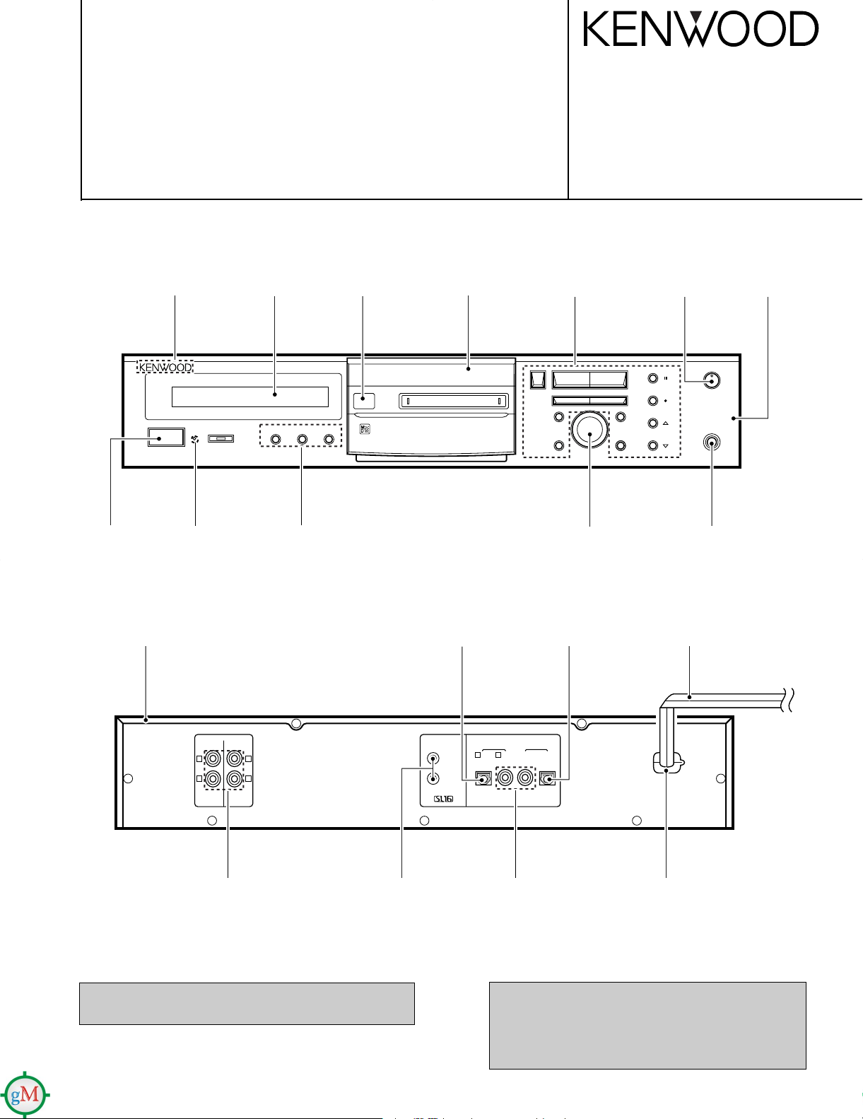
STEREO MINIDISC RECORDER
REC IN
R
L
R
L
PLAY OUT
(VARIABLE)
PLAY
OUT
OPT.COAX.
REC
IN
2 COAX.1 OPT.
LINE
SYSTEM
CONTROL
DIGITAL
MIN
REC LEVEL
PHONES
ENTER
/TIME DISPLAY
REC MODE/CHARAC.
SET
REC INPUT
MONITOR
/DELETE
STANDBY
POWER
JOG DIAL
TITLE INPUT
EDIT/SPACE
MAX
DISC LOADING MECHANISM
STEREO MINIDISC RECORDER
1
37
¡
0
- ON – OFF
TIMER
REC OFF PLAY
OUTPUT
LEVEL
4¢
REC
DMF-3020/3020(S)/5020
MD-203
SERVICE MANUAL
1998-9/B51-5480-00 (K/K) 2945
©
KENWOOD badge
(B43-0302-04)
Knob
(K27-2178-04)
Metallic cabinet
(A01-3635-01)
Front glass
(B10-3426-03)
Indicator
(B12-0353-04)
Filter
(B11-0376-04)
Knob
(K29-7412-02)
Escutcheon *
(B07-)
Optic receiving module
(W02-1181-05)
Knob
(K29-7412-02)
Knob
(K29-7536-04)
Oscillating module
(W02-1114-05)
Knob
(K29-7354-14)
Phone jack *
(E11-)
AC power cord *
(E30-)
Panel
(A60-1530-11)
Phono jack
(E63-1065-05)
In compliance with Federal Regulations, following are
reproductions of labels on, or inside the product relating to
laser product safety,
Miniature phono jack
(E11-0293-05)
Refer to 1050MD/DM-5090/DM-9090 service manual
(B51-5387-00) if you see the mechanism test mode.
Phono jack
(E63-0160-05)
KENWOOD-Corp. certifies this equipment conforms to
DHHS Regulation No.21 CFR 1040.10, Chapter 1,
Subchapter J.
DANGER : Laser radiation when open and interlock
Power cord bushing
(J42-0083-05)
Illustration is DMF-3020.
* Refer to parts list on page 23.
defeated.
AVOID DIRECT EXPOSURE TO BEAM.
Caution on condensation
Condensation (of dew) may occur inside the unit when there is a great
difference in temperature between this unit and the outside.
This unit may not function properly if condensation occurs. In this
case, leave the unit for a few hours with the power left ON, and
restart the operation after the condensation has dried up.
Be specially cautious against condensation in a following circumstance:
When this unit is carried from a place to another across a large
difference in temperature, when the humidity in the room where this
unit is installed increases, etc.
Memory backup
The typical period for which the memory can be backed up while the
power cord is unplugged or the
POWER
key is set to the
OFF
position
is about 3 weeks, though this may be variable depending on the
surrounding environment.
In case of long hours of power failure or slipping out of the power cord,
the data related to recording and editing (that is usually recorded at the
moment the Mini Disc is ejected) may be cleared or destroyed before
it is written in the Mini Disc. Remember that the data lost cannot be
recovered.
After recording or editing, be sure to eject the Mini Disc so that the
recording or editing data can be written in the disc.
Operation to reset
The microprocessor may fall into malfunction (impossibility to operate
erroneous display, etc.) when the power cord is unplugged while power
is ON or due to an external factor. In this case, execute the following
procedure to reset the microprocessor and return it to normal condition.
With the POWER key left to ON, unplug the power cord
from the power outlet then, while holding the eject (
0
)
key depressed, plug the power cord again.
÷ Please note that resetting the microprocessor clears the contents
stored in, it returns the microprocessor to the condition when it left
the factory.
Before transporting or moving this unit, carry out the
following operations.
1. Set the POWER key to ON without loading a Mini Disc.
÷ Check that no disc is present in the unit.
2. Wait a few seconds and verify that the display shown
appears.
3. Set the POWER key to OFF.
Note related to transportation and
movement
NO DIS
C
DMF-3020/3020(S)/5020/MD-203
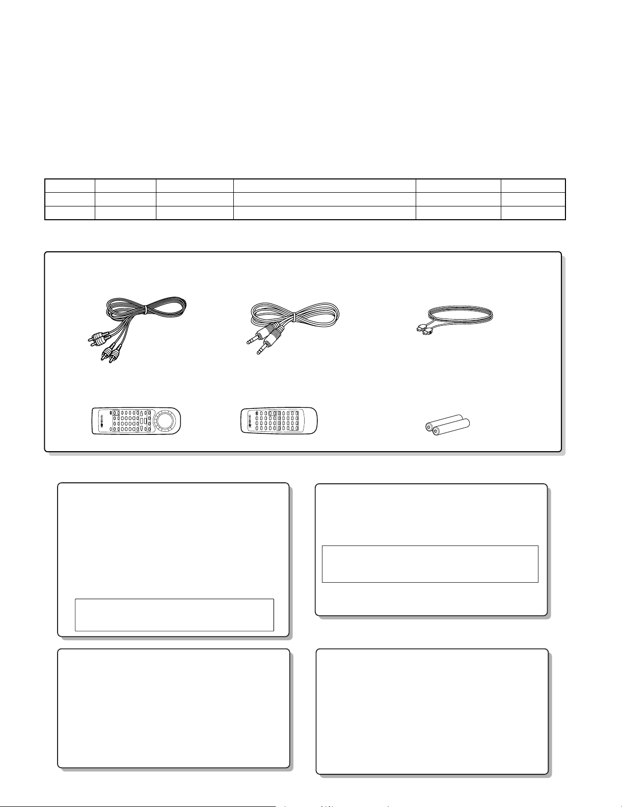
Remote control unit (1)
RC-M0705
(A70-1238-05) (A70-1239-05)
Battery cover (A09-1116-08) Battery cover (A09-0374-08)
(For DMF-5020)
Batteries (2)
R03 ("AAA"-size) batteries (For RC-M0705)
R6 ("AA"-size) batteries (For RC-M0302)
Check that the following accessories are present.
Audio
(E30-0505-05) (E30-2733-05) (B19-1529-05)
cord (2) System control cord (1) Optical fiber cable (1)
Remote control unit (1)
RC-M0302 (For DMF-3020/MD-203)
CONTENTS/ACCESSORIES/CAUTIONS
CONTENTS
CONTENTS/ACCESSORIES/CAUTIONS...................2
CONTROLS.................................................................3
BLOCK DIAGRAM.......................................................5
CIRCUIT DESCRIPTION.............................................6
PC BOARD ................................................................. 8
Refer to the Service manual, if you see the IC40, 41 on the X25 (PCB)
PCB Ref No. Parts No. Refer to Service manual Parts No. Page
X25 IC40 KAN06 DV-203/2070, DVF-5010/9010/K7010 B51-5456-00 20
X25 IC41 PCM1716E DV-203/2070, DVF-5010/9010/K7010 B51-5456-00 21
Accessories
SCHEMATIC DIAGRAM........................................... 11
EXPLODED VIEW .....................................................21
PARTS LIST...............................................................23
SPECIFICATIONS .......................................Back cover
Cautions
2
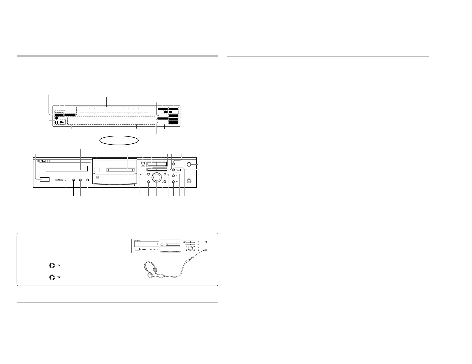
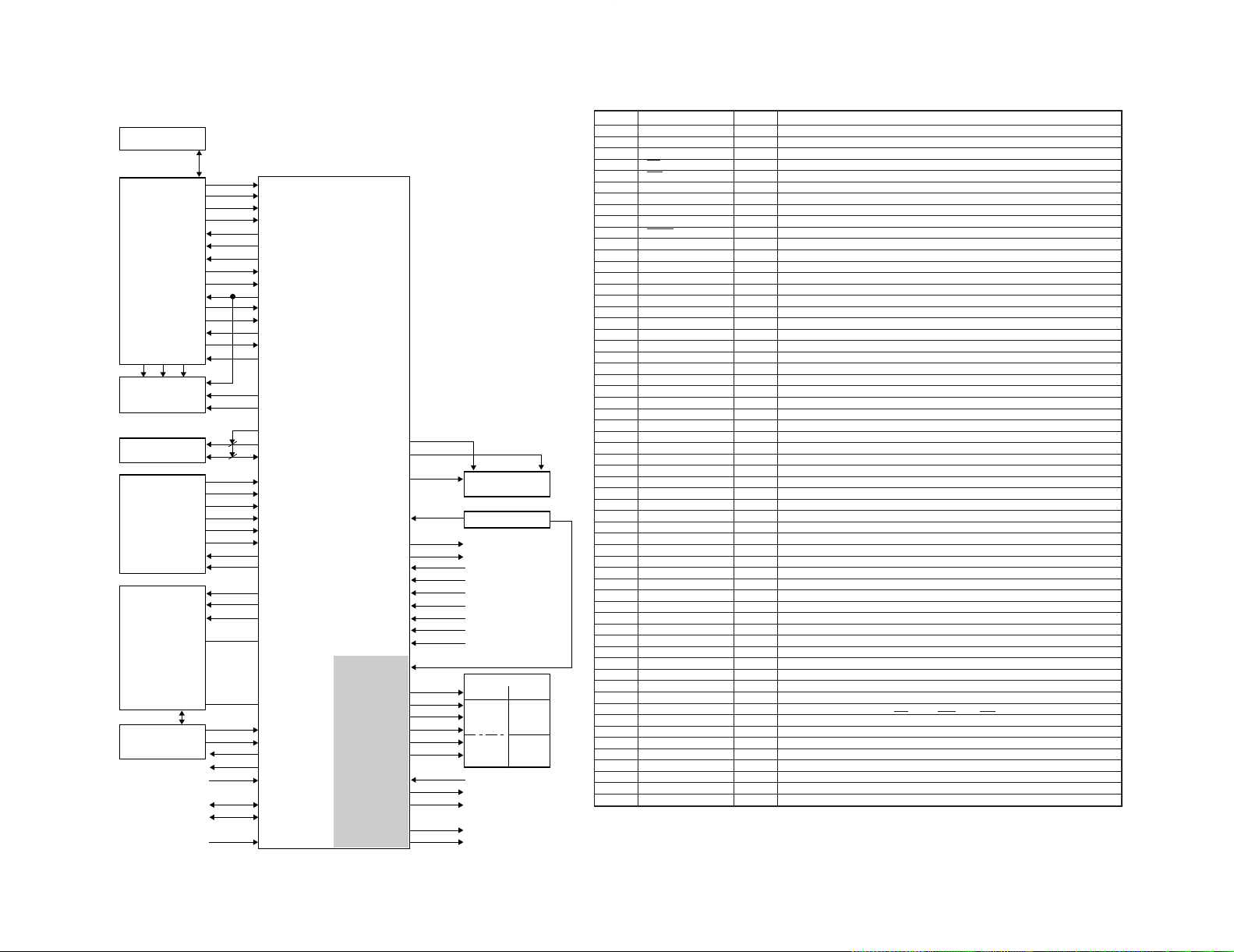
1 POWER key
: Press to turn the unit ON and OFF.
: The unit may enter the standby mode when the POWER key
is pressed to turn it ON. This is because the unit holds the
memory that it has been put to the standby mode by the
remote control unit in the last operation.
2 Remote control sensor
3 Mini Disc insertion slot
: When a Mini Disc is inserted while the unit is in the standby
mode, it is turned ON automatically.
4 Eject (0) key
: Press to eject the Mini Disc.
5 Stop (7) key
: Press to stop playback or recording.
6 Play (3) key
: Press to start playback.
7 Manual search down (1) key
: This key functions as the fast reverse key during playback.
: During an editing mode, press to move the title input cursor
or to scroll the track title display to the left.
8 Manual search up (¡) key
: This key functions as the fast forward key during playback.
: During an editing mode, press to move the title input cursor
or to scroll the track title display to the right.
9 Pause (8) key
: Press to let playback or recording pause temporarily.
0 REC LEVEL knob
: Rotate to adjust the analog recording level.
! TIMER switch
: This switch is used in timer playback and timer recording.
@ TITLE INPUT key
: Press to switch the title input mode ON/OFF.
# REC INPUT key
: Press to switch the recording input line between digital
(optical/coaxial), analog and monaural.
$ MONITOR/DELETE key
MONITOR
: Press to monitor the sound being input from the source
while the unit is in stop mode.
DELETE
: During title editing, press to delete a character. During track
editing, press to delete a track.
% REC MODE/CHARAC. (Character) key
REC MODE
: Press to switch the recording setting adjustment modes
(record modes) ON/OFF.
CHARAC.
: Press to select a character group during the title input
operation.
Description of main unit keys
^ SET key
: For use in setting the editing result and input title in memory.
: When pressed in the recording pause mode, the MEMORY
REC function is set and recording starts from the sound
approximately 6 seconds before the current sound.
& JOG DIAL
Skip down (4)/ Skip up(¢) knob
: During playback, rotate to skip tracks.
: Before starting recording in record mode, rotate to select the
recording setting adjustment mode.
: During title search, rotate to select a track number.
: During title input, rotate to select a track number or a
character.
: During editing, rotate to select the editing mode or a track
number.
* ENTER/TIME DISPLAY key
ENTER
: For use in executing the editing and title input operations.
TIME DISPLAY
: Press to switch the time and title display modes.
( EDIT/SPACE key
EDIT
: Press to switch the editing mode ON/OFF.
SPACE
: Press to insert a blank space character during the title input
operation.
) OUTPUT LEVEL DOWN (fi) key
: Use this to decrease the volume of the headphones and the
output level.
¡OUTPUT LEVEL UP (%) key
: Use this to increase the volume of the headphones and the
output level.
™Record (¶) key
: Press to start recording.
In stop mode
: When the ¶ key is pressed while a recordable disc is present
in the unit, it enters record-pause mode.
(It enters record-pause mode at the position immediately
after the last existing track.)
In record-pause mode
: When the ¶ key is pressed, the SOUND SYNCHRO REC
standby mode is set.
: In the SOUND SYNCHRO REC standby mode, the set
functions in the same way as in the normal recording pause
mode.
£PHONES jack
: Connect stereo headphones (optional) here.
MIN
REC LEVEL
PHONES
ENTER
/TIME DISPLAY
REC MODE/CHARAC.
SET
REC INPUT
MONITOR
/DELETE
STANDBY
POWER
JOG DIAL
TITLE INPUT
EDIT/SPACE
MAX
DISC LOADING MECHANISM
STEREO MINIDISC RECORDER
137¡
0
- ON – OFF
TIMER
REC OFF PLAY
2 3 4 5 6 7
@
# $ ^ £
)&
8
0
( ¡™
*!%
IN
REPEAT
FADE
OVER
OUT
OVER (
−dB)
(
−dB)
MONO
MANUAL
A . PAUSE
R
L
REMAIN
TOTAL
SINGLECOPY
TITLE
••••
•
•
•
•••••
∞
∞
912 7
5
1
3
40 30
21
18
0
1518 12
9
3
6
40 30
27
241521
0
SEARCHPGM
MONITOR
ANALOG
32kHz
2
13
48kHz
44.1kHz
DIGITAL
19
OUTPUT
LEVEL
4¢
REC
While the standby indicator of the unit is lit, a small amount of current is flowing into the unit's internal circuitry to back up the memory.
This condition is referred to as the standby mode of the unit. While the unit is in the standby mode, it can be turned ON from the remote
control unit.
Standby mode
Display / Main unit
Display
TITLE and SEARCH indicators
MONO indicator
PGM (Program) indicator
Peak level indicators
Listening through headphones
Plug the stereo headphones (with standard-plug) available in audio
stores into the
PHONES
jack and adjust the listening volume with the
OUTPUT LEVEL
control on the front panel. The default value is 0 dB
(maximum volume).
ANALOG input indicator
DIGITAL input 1/2 indicators
REPEAT indicator
SINGLE, TOTAL and
REMAIN indicators
Character information
display
A. PAUSE indicator
MANUAL indicator
MONITOR indicator
Operation indicators
¶ REC indicator
8 Pause indicator
3 Play indicator
Sumpling frequency
indicators
DMF-5020 only
OUTPUT
LEVEL
3
CONTROLS
DMF-3020/3020(S)/5020/MD-203
4
1
Numeric keys / Character editing keys
Numeric keys
0-9
: Press when selecting a track number
directly.
+10
: Press when selecting a track number
10 or more.
+100
: Press when selecting a track number
100 or more.
: These keys are also used to select a
character or symbol during title editing.
CHARACTER DELETE / CLEAR key
CHARACTER DELETE
: During title input, press to delete a
character.
CLEAR
: During editing, press to clear a selected
track number.
: In program mode, press to clear the
program.
CHARACTER SPACE / CHECK key
CHARACTER SPACE
: During title input, press to insert a blank
space character.
CHECK
: In program mode, press to check the
program contents.
CHARA. (Character)/ P.MODE (Play
Mode) key
CHARA.
: Press to select a character group dur-
ing the title input operation.
P.MODE
: Press to initiate the program mode.
5
Editing mode keys
REC INPUT key
: Press to switch the recording input line
between digital (optical/coaxial), analog
and monaural.
EDIT key
: Press to switch the editing mode ON/
OFF.
SET key
: This key is used in the title assignment or
editing operations.
: When pressed in the recording pause
mode, the MEMORY REC function is set
and recording starts from the sound approximately 6 seconds before the current sound.
ENTER key
: Press to execute editing or enter the
input title in memory.
7
Applied operation keys
EDIT CANCEL key
: Press to cancel the editing operation.
TITLE INPUT key
: Press to switch the title input mode ON/
OFF.
TITLE SEARCH key
: Press to switch the title search mode
ON/OFF.
: During title editing, press to switch the
title change input mode between the
“overwrite mode” and “insert mode”.
TIME DISPLAY key
: Press to switch the time and title display
modes.
AUTO PAUSE key
: When this key is pressed, the pause
mode is initiated automatically at the
point where the track number changes
during playback.
: When pressed in the recording or record-
ing standby mode, the AUTO REC PAUSE
mode is turned on.
AUTO/MANU. key
: Selects whether the track numbers are
to be marked automatically during recording (AUTO) or to be marked manually after it (MANUAL).
MONITOR key
: Press to monitor the sound being input
from the source while the unit is in stop
mode.
METER MODE key
: Press to switch the level meter display
contents.
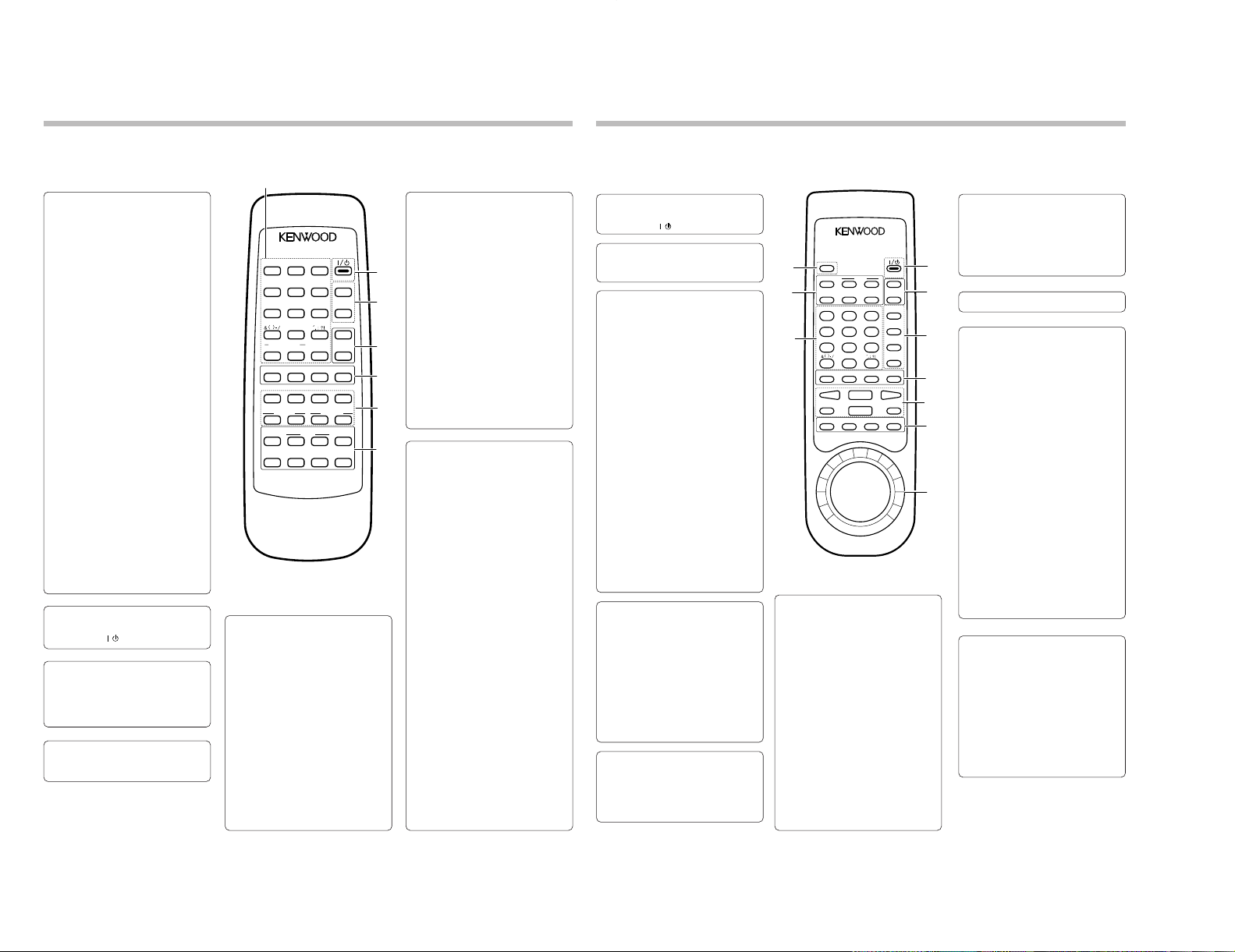
Remote control unit (DMF-3020/MD-203)
The remote control unit incorporates the basic operation keys as well as a variety of applied operation keys so that it can be
used in a wide range of purposes.
The keys on the remote control unit with the same names as on the main unit have the same function as the keys
on the main unit.
Model: RC-M0302
Infrared ray system
3
REPEAT key
: Press to switch the repeat modes for
repeat playback.
RANDOM key
: Press to initiate the random play mode.
2
ON/STANDBY key
: Press to turn the unit between ON and
STANDBY (
/ ) modes.
6
Basic operation keys
¶ : Record key
8 : Pause key
7 : Stop key
3 : Play key
CURSOR / 1 , ¡ keys
1 , ¡
: During playback, press to fast forward
or fast reverse the play.
CURSOR
: During title input, press to move the
cursor.
CHARACTER/SEARCH/4 , ¢ keys
CHARACTER
: Press to select a character group dur-
ing the title input operation.
SEARCH
: During title search, rotate to select a
track number.
4 , ¢
: During playback, press to skip tracks in
the forward or reverse direction.
ABC1DEF
23
JKL MNO
5
GHI
46
TUV WXY
8
PRS
79
POWER
EDIT
CANCEL
QZ
0+100 +10
RANDOM
REPEAT
SPACE CHARA.
CHECK
DELETE
CLEAR
P.MODE
EDIT SET
REC INPUT
ENTER
87
¡
14¢
AUTO
PAUSE
AUTO
/MANU.
METER
MODE
TIME
DISPLAY
OUTPUT
LEVEL
MONITOR
REMOTE CONTROL UNIT
RC-M0302
CURSOR
TITLE
CHARACTER
/SEARCH
CHARACTER
%
fi
÷
£
INPUT
SEARCH
2
3
4
5
6
7
1
4
OUTPUT LEVEL (%fi) keys
: Use these to adjust the output level and
the volume of the headphones.
3
Character editing keys
TIME DISPLAY key
: Press to switch the time and title display
modes.
CHARA. (Character)/ P.MODE (Play
Mode) key
CHARA.
: Press to select a character group dur-
ing the title input operation.
P.MODE
: Press to initiate the program mode.
DELETE / CLEAR key
DELETE
: During title input, press to delete a
character.
CLEAR
: During editing, press to clear a selected
track number.
: In program mode, press to clear the
program.
SPACE / CHECK key
SPACE
: During title input, press to insert a blank
space character.
CHECK
: In program mode, press to check the
program contents.
8
EJECT (0) key
9
Editing mode keys
EDIT CANCEL key
: Press to cancel the editing operation.
TITLE INPUT key
: Press to switch the title input mode ON/
OFF.
TITLE SEARCH key
: Press to switch the title search mode
ON/OFF.
: During title editing, press to switch the
title change input mode between the
“overwrite mode” and “insert mode”.
SET key
: This key is used in the title assignment or
editing operations.
: When pressed in the recording pause
mode, the MEMORY REC function is set
and recording starts from the sound approximately 6 seconds before the current sound.
ENTER key
: Press to execute editing or enter the
input title in memory.
EDIT key
: Press to switch the editing mode ON/
OFF.
Remote control unit (DMF-5020)
The remote control unit incorporates the basic operation keys as well as a variety of applied operation keys so that it can be
used in a wide range of purposes.
The keys on the remote control unit with the same names as on the main unit have the same function as the keys
on the main unit.
Model: RC-M0705
Infrared ray system
4
MONITOR key
: Press to monitor the sound being input
from the source while the unit is in stop
mode.
METER key
: Press to switch the level meter display
contents.
RANDOM key
: Press to initiate the random play mode.
REPEAT key
: Press to switch the repeat modes for
repeat playback.
1
ON/STANDBY key
: Press to turn the unit between ON and
STANDBY (
/ ) modes.
6
Recording-related keys
REC MODE key
: Press to switch the recording setting ad-
justment modes ON/OFF.
AUTO/MANU. key
: Selects whether the track numbers are
to be marked automatically during recording (AUTO) or to be marked manually after it (MANUAL).
AUTO PAUSE key
: When this key is pressed, the pause
mode is initiated automatically at the
point where the track number changes
during playback.
: When pressed in the recording or record-
ing standby mode, the AUTO REC PAUSE
mode is turned on.
REC INPUT key
: Press to switch the recording input line
between digital (optical/coaxial), analog
and monaural.
5
Basic operation keys
3 : Play key
4 , ¢ : Skip down/up keys
¶ : Record key
7 : Stop key
8 : Pause key
7
CURSOR / 1 , ¡ shuttle
CURSOR
: During title input, rotate to move the
cursor.
1 , ¡
: Use this during playback for forward and
reverse search.
2
OUTPUT LEVEL (%fi) keys
: Use these to adjust the output level and
the volume of the headphones.
0
Numeric keys
0-9
: Press when selecting a track number
directly.
+10
: Press when selecting a track number 10
or more.
+100
: Press when selecting a track number
100 or more.
: These keys are also used to select a
character or symbol during title editing.
8
9
0
REMOTE CONTROL UNIT
RC-M0705
0
EDIT CANCEL
TITLE
INPUT
SET
ENTER
ABC
1
2
GHI
JKL
4
5
PRS
TUV
7
8
QZ
+100
0
MONITOR
METER
RANDOM
4 ¢
÷
7
REC MODE
AUTO/MANU.
AUTO PAUSE
™™
/CUR.L CUR.R/
SEARCH
EDIT
DEF
MNO
WXY
+10
DMF-3020/3020(S)/5020/MD-203
1
POWER
%
OUTPUT
2
LEVEL
fi
TIME
DISPLAY
3
CHARA.
6
P.MODE
3
DELETE
9
CLEAR
SPACE
CHECK
REPEAT
£
8
REC INPUT
4
5
6
££
7
CONTROLS

RF,TE,FE,SE
CONT,BUS
APC REF
I,J,
A,B,C,D,E,F
SPINDLE
FEED
FCS,TRK,SPIN,SLED PWM
AUDIO
SYSTEM
AC
TRK
FCS
VFL
DATA
LRCK
BCK
DATA IN/OUT
LRCK
BCK
+3.3V
MECHA: MDM-04 (X33-1100-00)
X25-618 (A/5) (B/5)
DMF-3020/5020
DMF-5020 ONLY
X25 (C/5) (D/5)
X25 (E/5)
MAIN
u-COM
UPD784215GF532
256K SRAM
IC31
POWER
TRANSFORMER
FILTER
LINE
AVR
AVR
AVR
AVRANALOG +3.3V
DIGITAL HEAD MOTOR
+5V
BACK-UP
ACIRC
DSP
SERVO
ATRAC
MEMO. CONT
(CXD2652AR)
(CXA2523AR)
RF AMP
IC1
SERVO
(BH6511FP)
MOTOR
DRIVER
IC2
IC8
M
M
M
PLAY POS. SW
DRAM
IC3
PICKUP
KMS-260A
FL
ED1 LC7571ONE
FL DOT MATRIX
DRIVER
IC23
KEY
MATRIX
TIMER SW
IC11
JOG
REC SW
REFRECT SW
PROTECT SW
START LIMIT SW
DISC IN SW
BUFFER
IC37
REG.
+3.3V
DIGITAL+5V
3.3
LOADING MOTOR
FEED
MOTOR
Q7
LASER DRIVE APC
DISC
MOTOR
DISC
IC35
LOADING MOTOR
DRIVER
TA8409S
PHONES
OUT
IN
ANALOG
COAX. IN
OPT. IN
COAX. OUT
OPT. OUT
CONTROL
SYSTEM
SL16
DIGTAL
INPUT
OUTPUT
DIGITAL
TEMP. DET.
AC
u-COM VDD
u-COM +5V
33V
FL AC
DIGITAL
IC5
HEAD
RECORDING
CONTROL
REMOTE
5.0
5.0 3.3
E PROM
2
HEAD DRIVER
3.3 5.0
NON REG: 16V
3.3V 4Mx1
SENSOR
DAC
ADC
DIGITAL
DIGITAL
512FS KAN06
DAC
DRIVE
DIGITAL
DIGITAL
ANALOG
IC10
MUTE
Q17-20
LEVEL
REC
VR1
IC26
IC21 (1/3)
IC21 (2/3)
DIGITAL
IC21 (3/3)
IC10
IC6
IC36
CM1777M
A3
S18
S1
IC34
IC38
IC8
IC13
AMP
H.P
J4
A1
A2
J3
D1
Q1
Q7
Q11
Q13
IC22 IC40 IC41
IC39
SRAM +5V
SHUNT
OUT
IN
ANALOG
2V/0.4k
0.5V/22k
15~ 21dBm
0.5Vp-p/75COAX.
DIGITAL (IN/OUT)
OPT.
5
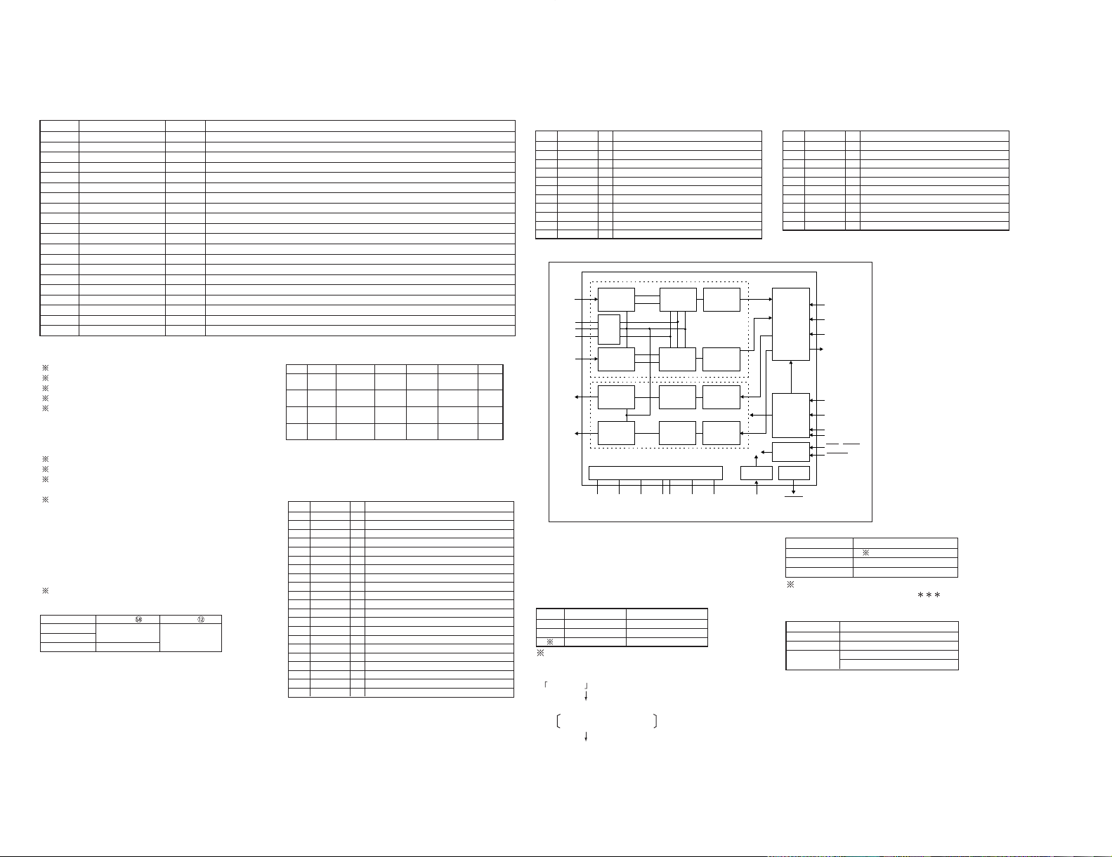
BLOCK DIAGRAM
DMF-3020/3020(S)/5020/MD-203
6
No. Name I/O Description
1,2 - O N.C.
3 DARST O DAC reset
4 DINSEL O Digital 1/2 select H; DIGITAL 1
5 RD O SRAM read strobe
6 WR O SRAM write strobe
7 CS O SRAM CS L; SRAM enable
8 ASTB O SRAM address strobe
9 Vdd - Power supply (Microprocessor)
10 POWER O Power terminal H; Power ON
11 MUTE O Mute control output L; Mute ON
12 INISW2 I Destination selector L; DMF-3020/5020
13 SCHNG O E2PROM data IN/OUT change-over H; SDA output
14 SBUSY I/O 16 serial busy
15 SDATA I/O 16 serial data
16 SCL O E2PROM clock
17 SDA I/O E2PROM data
18 LDON O Laser ON / OFF control port H; LD ON
19 RMS O Pick RMS H; ON
20 XLAT O System IC latch
21 SENS I System IC sens
22 Vpp - GND
23 PROTECT I Detection port of protect switch L; Protect ON
24 REFLECT I Detection port of reflect switch H; Low reflect
25 DISCIN I Detection of disc input switch L; Disc out SW ON
26 STTLMT I Detection port of limit switch L; Start limit SW ON
27 PHOTSW I Detection of mechanism play position L; Photo sensor ON
28 REC SW I Input port of detection from REC position switch L; REC SW ON
29 LOADIN O Output port of loading motor control signal L; Loading OUT
30 LOADOUT O Output port of loading motor control signal L; Loading IN
31 MNT0 I FOK signal from CXD2652AR (IC2) L; Focus ON
32 MNT2 I Input port of monitor 2 from CXD2652AR (IC2)
33 XRST O Output port of reset signal to CXD2652AR (IC2)
34 TX O Output port of recording permitted signal
35 RECP O Laser power control to CXD2652AR (IC2)
36 MNT3 I Input port of monitor 3 from CXD2652AR (IC2)
37 Vdd - Power supply (Microprocessor)
38,39 -- Clock IN / OUT (12.5MHz)
40 GND - GND
41 OPEN O No used
42 GND I No used
43 RESET I Microprocessor hard reset
44 REM I Remocon signal input terminal
45 XINT I Input port of interrupted status from CXD2652AR (IC2)
46 CE I Microprocessor chip enable H; Enable / L; disable
47 SQSY I Input port of sub code Q from CXD2652AR (IC2)
48 DQSY I U-bit of digital IN / SUB Q sync input of CD format from CXD2652AR (IC2)
49 DDQSY I N.C.
50 MNT1 I Input port of track jump detection from CXD2652AR (IC2)
51 Vdd - Microprocessor power supply (+5V)
52 AVref 0 - A/D reference voltage (Connect Vdd)
53~56 KR0~KR3 I Key return (KR0~KR3)
57 TMSW I Timer switch input 0.0V
OFF
1.25V
PLAY
3.7V
REC
5.0V
58 INISW1 I Detection selector
59 BACK I Back up voltage detection (Less than 2.2V : NG)
60 PROT I Protection detection
61 GND - GND
62 BACK ON O Back up charge control H; Charge ON
63 ENCA I Rotary encoder A
64 AVref 1 - D/A reference voltage (+5V)
65 SRDT I Data for reading input from CXD2652AR (IC2)
1-2 Pin description
1. Main microprocessor : uPD784215GF532 (X25: IC31)
1-1 Microprocessor peripley block diagram
E2PROM
RF AMP
ML:77
ADRST:83
PROT:60
DINSEL:4
STBLED:76
RECLED:86
DRON:71
MC:79
DARST:3
MD:78
ENCB:70
31:MNT0
50:MNT1
ATRAC
DRAM
(X33) IC7
(X33) IC2
(X33) IC1
(X33) IC6
(X25) IC34
(X25) IC33
36:MNT3
32:MNT2
CXD2652AR
66:SWDT
20:XLAT
67:SCLK
65:SRDT
33:XRST
21:SENS
47:SQSY
48:DASY
45:XINT
35:RECP
34:TX
18:LDON
MAIN
u-COM
19:RMS
CXA2523AR
13:SCHNG
DWDT:74
DCLK:75
17:SDA
16:SCL
LC75710NE
ENCODER
FL DRIVER
(X25) S1
(X25) IC1
FLDCE:72
23:PROTECT
24:REFLECT
25:DISCIN
(MDM-04)
MD MECHA.
ENCA:70
27:PHOTSW
26:STTLMT
POWER:10
28:RECSW
MUTE:11
29:LOADIN
INISW2:12
INISW1:58
30:LOADOUT
TMSW:57
5:RD
KR2:55
KR3:56
7:CS
6:WR
SRAM
8BIT MEMORY
LATCH
AD/DA CONVERTER
KR1:54
KR0:53
~~
84:AD0
91:AD7
– BUS –
DMF3020
MD203
DMF5020
92:A8
PCM1716
PCM3002
98:A14
RESET:43
PCM3003
(AD)(AD)
(DA)(DA)
CE:46
BACKCHK:85
BACKV:59
BACKON:62
SDATA:15
SBUSY:14
REM:44
DMF-3020/3020(S)/5020/MD-203
CIRCUIT DESCRIPTION
PIN PIN NAME I/O DESCRIPTION
1,2 VCC1 - ADC ANALOG POWER SUPPLY
3 VINR I RCH ANALOG INPUT
4,5 VREF1,2 - REFERENCE VOLTAGE 1,2
6 VINL I LCH ANALOG INPUT
7 PDAD I ADC POWER DOWN L: ON
8 PDDA I DAC POWER DOWN L: ON
9 SYSCK I SYSTEM CLOCK INPUT256fs 384fs 512fs
10 LRCIN I SAMPLING CLOCK INPUT
11 BCKIN I BIT CLOCK INPUT
12 DOUT O DIGITAL AUDIO DATA OUTPUT
13 DGND - DIGITAL GND
PIN PIN NAME I/O DESCRIPTION
14 VDD - DIGITAL POWER SUPPLY
15 DIN I DIGITAL AUDIO DATA INPUT
16 20BIT I 20/16 BIT DATA FORMAT CHOICE
17,18 DEM1,0 I DE-EMPHASIS CONTROL 1,0
19 VOUTL O LCH ANALOG OUTPUT
20 VOUTR O RCH ANALOG OUTPUT
21 VCOM - ANALOG AMP COMMON
22 AGND2 - DAC ANALOG GND
23 AGND1 - ADC ANALOG GND
24 VCC2 - DAC ANALOG GND
(PCM3003E:DMF-5020)
VL
IN
VR
IN
VL
OUT
VR
DAC
ADC
OUT
V1
REF
V2
REF
V
COM
AGND2
( ) PCM-3003
AGND1 DGND1
Vcc2 Vcc1 Vcc SYSCK
ZERO
(PCM 3002ONLY)
(PDDA)
(20BIT)
ML
MD(DEM1)
MC(DEM0)
DOUT
DIN
BCKIN
LRCIN
RST(PDAD)
Analog
front-end
Analog
front-end
∆∑
Modulator
∆∑
Modulator
(+)
(-)
(+)
(-)
Analog
L.P.F.
Analog
L.P.F.
MPX level
∆∑
modulator
MPX level
∆∑
modulator
Zero
detect
Decimation
H.P.F.
Decimation
H.P.F.
Serial I/O
Model/format
control I/O
Reset
power down
Zero
detect
CLOCKPower supply
8fs O.S.F.
(Inter pol.)
Vref
2-2 Block diagram
3. Test mode of the unit
3-1 Setting of the test mode
While pressing the [REC/INPUT] key, plug the AC power
cord into the AC wall outlet.
3-2 Contents of the test mode
Choose the 3 mode by TIMER switch position below.
NONE means none mode.
(1) [ INSPECTION ] mode
•
ENGLISH display (2secs)
• " NIAGARA TEST " display
Dot : Niagara
Segment : All lighting
• Push a key, then cancel " NIAGARA TEST "
Display [ KEY 028 ] into the KEY-TEST mode.
Push a key, then display [ KEY
] .
(2) [ ERROR RATE ] mode
• Function of the key
• Function of the key
4. Microprocessor reset
The microprocessor can be initialized while pressing the
[EJECT] key, plug the AC power cord into the AC wall
outlet.
5. Mechanism test mode
Refer to 1050MD/DM-5090/MD-9090 service manual (B515387-00), if you see this test mode.
TIMER SW Mode
(1) REC INSPECTION
(2) PLAY ERROR RATE
OFF NONE
Key Mode
REC/INPUT KEY-TEST
EDIT NIAGARA TEST
TITLE INPUT None all lighting
Key Function
PLAY CPLAY (MID)
REC CREC (MID)
STOP
STOP CPLAY, CREC
(2time push) ERROR RATE
PIN PIN NAME I/O DESCRIPTION
1,2 VCC1 - ADC ANALOG POWER SUPPLY
3 VINR I RCH ANALOG INPUT
4,5 VREF1,2 - REFERENCE VOLTAGE 1,2
6 VINL I LCH ANALOG INPUT
7 RST I RESET L: ON
8 ML I CONTROL DATA INPUT LOAD STOROBE
9 SYSCK I SYSTEM CLOCK INPUT256fs 384fs 512fs
10 LRCIN I SAMPLING CLOCK INPUT
11 BCKIN I BIT CLOCK INPUT
12 DOUT O DIGITAL AUDIO DATA OUTPUT
13 DGND - DIGITAL GND
14 VDD - DIGITAL POWER SUPPLY
15 DIN I DIGITAL AUDIO DATA INPUT
16 ZERO I ZERO FLAG OUTPUT L: ON
17 MD I CONTROL DATA INPUT
19 VOUTL O LCH ANALOG OUTPUT
20 VOUTR O RCH ANALOG OUTPUT
21 VCOM - ANALOG AMP COMMON
22 AGND2 - DAC ANALOG GND
23 AGND1 - ADC ANALOG GND
24 VCC2 - DAC ANALOG GND
0.0 V 0.8 V 1.6 V 2.4 V 3.2 V 4.0 V
KR0 – TT INPUT REC – MONITOR/ –
INPUT DEL
KR1 EJECT STOP FB REC SET –
MODE
KR2 PLAY FF EDIT/ – ENTER/ –
SPACE TIME
KR3 PAUSE REC LEVEL LEVEL – –
UP DOWN
Vdd=5.0V
5.0V : KEY OFF
1-3 Initialization
POWER = ON (DM-9090,DM-5090)
REC INPUT = ANALOG
AUTO CUT = OFF
AUTO/MANUAL = AUTO
OUTPUT LEVEL = 0 dB
PLAY MODE = TRACK
REPEAT = OFF
TIME DISPLAY = SINGLE(+)
LEVEL METER MODE = NORMAL MODE
AUTO TNO TIME = 2 sec
AUTO TNO LEVEL = 0 (-55 dB)
REC END WRITE = ON
DRIVE = ON
PRESET TITLE = PRE1 : Pops
PRE2 : Rock
PRE3 : Classic
PRE4 : Jazz
PRE5 : Disco
PRE6 : Best Hits
PRE7 : Air Check
PRE8 : No.
PRE9 : Vol.
: Backup item
1-5 Key voltage matrix
Model INISW INISW
DMF-3020
3.5 (V)
MD-203 LOW
DMF-5020 1.5 (V)
1-4 Switch control table
No. Name I/O Description
66 SWDT O Data for writing to CXD2652AR (IC2)
67 SCLK O Serial clock to CXD2652AR (IC2)
68,69 - - N.C.
70 ENCB I Communication to sub u-COM (IC28) Rotary encoder B
71 DRON O DSP (D.R.I.V.E ¿ : IC40) drive on H; ON
72 FLDCE O Latch to FL driver
73 - I N.C.
74 DWDT O Data to LC75710NE (IC1)
75 DCLK O Clock to LC75710NE (IC1)
76 STB LED O Latch to LC8904Q (IC23) Standby LED ON/OFF H; ON
77 ML O DAC (IC41) control latch
78 MD O DAC (IC41) control data
79 MC O DAC (IC41) control clock
80 - O No used / pull up
81 BACKCHK O Back up voltage check
82 REC LED O Clock to SM5844AF (IC25) REC LED ON/OFF H; ON
83 ADRST O Data to SM5844AF (IC25) ADC reset
84~91 AD0~AD7 O SRAM address / data (AD0~AD7)
92~99 A8~A15 O SRAM address (A8~A15)
100 Vss - GND
2. AD/DA converter :
PCM3002E, PCM3003E (X25: IC8)
2-1 PIN DESCRIPTION
(PCM3002E: DMF-3020,MD-203)
7
CIRCUIT DESCRIPTION
DMF-3020/3020(S)/5020/MD-203

A BDCE
PC BOARD (Component side view)
1
2
3
4
5
6
7
8
Refer to the schematic diagram for the value of resistors and capacitors.
 Loading...