

Page 1

8-Inch WIDE MONITOR
LZ-800W
INSTRUCTION MANUAL
Take the time to read through this instruction manual.
Familiarity with installation and operation procedures will help you
obtain the best performance from your new monitor.
For your records
Record the serial number, found on the back of the unit, in the spaces
designated on the warranty card, and in the space provided below. Refer to
the model and serial numbers whenever you call upon your KENWOOD dealer
for information or service on the product.
Model LZ-800W Serial number
© PRINTED IN JAPAN B64-1715-00 (W) (+)
01/12 11 10 9 8 7 6 5 4 3 2 1 00/12 11 10 9 8 7
Page 2

Contents
SSaaffeettyy PPrree ccaauutt ii oonnss .. .. .. .. .. .. .. .. .. .. .. .. .. .. .. .. .. .. .. .. .. .. .. .. .. .. .. .. .. .. .. .. .. .. .. .. .. .. .. .. .. .. ..
MMoonniittoorr CCoonnttrrooll FFuunn ccttiioonn
Power . . . . . . . . . . . . . . . . . . . . . . . . . . . . . . . . . . . . . . . . . . . . . . . . . . . . . . . . . . . . . . . . . . . . . . . . . . . . .4
English
Switching the Monitor’s Picture . . . . . . . . . . . . . . . . . . . . . . . . . . . . . . . . . . . . . . . . . . . . . . . . . . . . . . . . .4
Adjusting the Volume of the built-in speaker . . . . . . . . . . . . . . . . . . . . . . . . . . . . . . . . . . . . . . . . . . . . . . .4
Switching the Speaker Mode . . . . . . . . . . . . . . . . . . . . . . . . . . . . . . . . . . . . . . . . . . . . . . . . . . . . . . . . . . .4
Switching the TV/Video Screen Mode . . . . . . . . . . . . . . . . . . . . . . . . . . . . . . . . . . . . . . . . . . . . . . . . . . . .4
Switching the AV Output . . . . . . . . . . . . . . . . . . . . . . . . . . . . . . . . . . . . . . . . . . . . . . . . . . . . . . . . . . . . . .5
Adjusting the Picture Quality . . . . . . . . . . . . . . . . . . . . . . . . . . . . . . . . . . . . . . . . . . . . . . . . . . . . . . . . . . .5
SSyy sstteemm SSeettuupp FFuunnccttiioo nn
Setting the System . . . . . . . . . . . . . . . . . . . . . . . . . . . . . . . . . . . . . . . . . . . . . . . . . . . . . . . . . . . . . . . . . .6
Adjusting the Touch Position . . . . . . . . . . . . . . . . . . . . . . . . . . . . . . . . . . . . . . . . . . . . . . . . . . . . . . . . . . .7
Selecting the Reception Area (When the KTC-V800P is connected) . . . . . . . . . . . . . . . . . . . . . . . . . . . . .7
TTVV CC oo nn ttrroo ll FF uu nncc ttii oonn
Switching to the TV Control Screen . . . . . . . . . . . . . . . . . . . . . . . . . . . . . . . . . . . . . . . . . . . . . . . . . . . . . .8
Selecting the Preset Bands . . . . . . . . . . . . . . . . . . . . . . . . . . . . . . . . . . . . . . . . . . . . . . . . . . . . . . . . . . . .8
Selecting the Tuning Mode . . . . . . . . . . . . . . . . . . . . . . . . . . . . . . . . . . . . . . . . . . . . . . . . . . . . . . . . . . . .8
Selecting the Channels . . . . . . . . . . . . . . . . . . . . . . . . . . . . . . . . . . . . . . . . . . . . . . . . . . . . . . . . . . . . . . .8
Station Preset Memory . . . . . . . . . . . . . . . . . . . . . . . . . . . . . . . . . . . . . . . . . . . . . . . . . . . . . . . . . . . . . . .8
Auto Memory Entry . . . . . . . . . . . . . . . . . . . . . . . . . . . . . . . . . . . . . . . . . . . . . . . . . . . . . . . . . . . . . . . . . .8
Recalling a Preset Station . . . . . . . . . . . . . . . . . . . . . . . . . . . . . . . . . . . . . . . . . . . . . . . . . . . . . . . . . . . . .8
Selecting the Channels on the TV Picture Screen . . . . . . . . . . . . . . . . . . . . . . . . . . . . . . . . . . . . . . . . . . .9
RReemmoottee CCoonnttrrooll FFuunn ccttiioonn
<< WWhh eenn TThhee KK TTCC-- VV 8800 00NN// KKTT CC --VV88 0000 PP iiss ccoo nn nn eecc tt eedd >>
<< PPrroovv iidd eedd wwii tthh tthh ee KKTTCC--VV88 0000 NN //KKTT CC --VV88 0000 PP >>
.. .. .. .. .. .. .. .. ..
IInnssttaallll aa ttii oonn
Accessories . . . . . . . . . . . . . . . . . . . . . . . . . . . . . . . . . . . . . . . . . . . . . . . . . . . . . . . . . . . . . . . . . . . . . . .11
Installation Procedure . . . . . . . . . . . . . . . . . . . . . . . . . . . . . . . . . . . . . . . . . . . . . . . . . . . . . . . . . . . . . . . .11
Installation for Monitor Unit . . . . . . . . . . . . . . . . . . . . . . . . . . . . . . . . . . . . . . . . . . . . . . . . . . . . . . . . . . .12
Installation for the Video Box Unit . . . . . . . . . . . . . . . . . . . . . . . . . . . . . . . . . . . . . . . . . . . . . . . . . . . . . .13
Connecting the Power . . . . . . . . . . . . . . . . . . . . . . . . . . . . . . . . . . . . . . . . . . . . . . . . . . . . . . . . . . . . . . .13
Connecting the Headphone / AV Equipments . . . . . . . . . . . . . . . . . . . . . . . . . . . . . . . . . . . . . . . . . . . . .14
TTrroo uubbll eesshhoooo ttii nn gg GG uuii dd ee .. .. .. .. .. .. .. .. .. .. .. .. .. .. .. .. .. .. .. .. .. .. .. .. .. .. .. .. .. .. .. .. .. .. .. .. .. .. ..
SSppee cciiffiicc aa tt iioo nnss .. .. .. .. .. .. .. .. .. .. .. .. .. .. .. .. .. .. .. .. .. .. .. .. .. .. .. .. .. .. .. .. .. .. .. .. .. .. .. .. .. .. .. .. ..
33
11 00
11 55
11 66
2
The control screens shown in this manual are for explanation purposes only.
The actual screens and design differ.
Page 3
Safety Precautions
2WARNING
To prevent injury and/or fire, take the
following precautions:
• Ensure that the unit is securely installed. Otherwise
it may fly out of place during collisions and other
jolts.
• When extending the ignition or ground wires, make
sure to use automotive-grade wires or other cables
with an area of 0.75mm
2
(AWG18) or more to
prevent wire deterioration and damage to the wire
coating.
• To prevent short circuits, never put or leave any
metallic objects (e.g., coins or metal tools) inside the
unit.
• If the unit starts to emit smoke or strange smells,
turn off the power immediately and consult your
Kenwood dealer
• Be careful not to drop the unit or subject it to strong
shock.
The unit may break or crack because it contains
glass parts.
• Do not touch the liquid crystal fluid if the LCD is
damaged or broken due to shock. The liquid crystal
fluid may be dangerous to your health or even fatal.
If the liquid crystal fluid from the LCD contacts your
body or clothing, wash it off with soap immediately.
2CAUTION
To prevent damage to the machine, take the
following precautions:
• Make sure to ground the unit to a negative 12V DC
power supply.
• Do not open the back covers of the unit.
• Do not install the unit in a spot exposed to direct
sunlight or excessive heat or humidity. Also avoid
places with too much dust or the possibility of water
splashing.
• Do not subject the monitor unit to excessive shock,
as it is a piece of precision equipment.
• When replacing a fuse, only use a new one with the
prescribed rating. Using a fuse with the wrong
rating may cause your unit to malfunction.
• To prevent short circuits when replacing a fuse, first
disconnect the wiring harness.
• Do not use any screws except for the ones
provided. The use of improper screws might result
in damage to the main unit.
• You cannot view TV/ video pictures whilst the
vehicle is moving. To enjoy TV/ video pictures, find a
safe place to park and engage the parking brake.
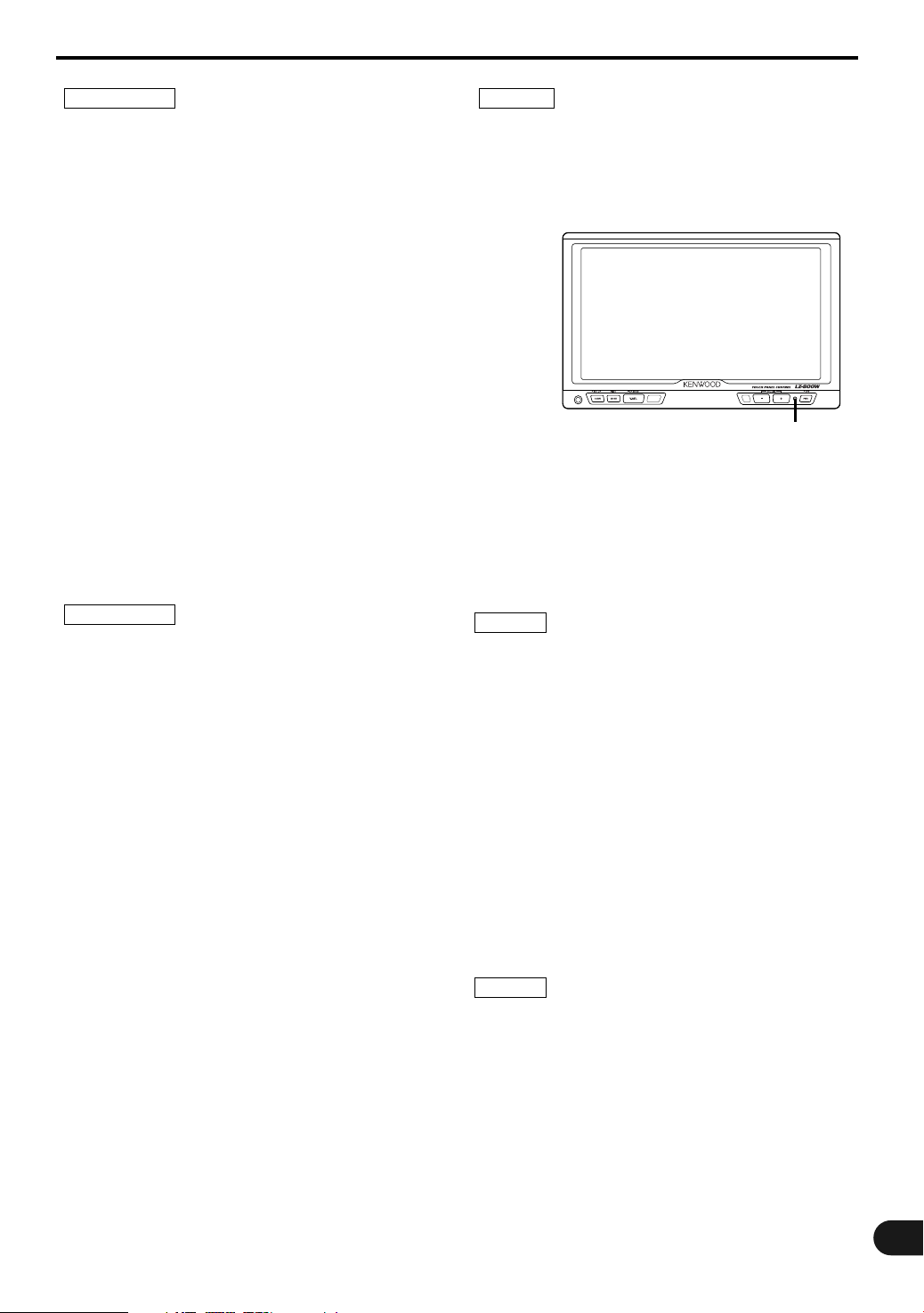
NOTE
• If you experience problems during installation,
consult your Kenwood dealer.
• If the unit does not seem to be working right, try
pressing the reset button first. If that does not solve
the problem, consult your Kenwood dealer.
Reset button
FCC WARNING
This equipment may generate or use radio
frequency energy. Changes or modifications to this
equipment may cause harmful interference unless
the modifications are expressly approved in the
instruction manual. The user could lose the
authority to operate this equipment if an
unauthorized change or modification is made.
NOTE
This equipment has been tested and found to comply with
the limits for a Class B digital device, pursuant to Part 15
of the FCC Rules. These limits are designed to provide
reasonable protection against harmful interference in a
residential installation. This equipment may cause harmful
interference to radio communications, if it is not installed
and used in accordance with the instructions. However,
there is no guarantee that interference will not occur in a
particular installation. If this equipment does cause
harmful interference to radio or television reception, which
can be determined by turning the equipment off and on,
the user is encouraged to try to correct the interference by
one or more of the following measures:
• Reorient or relocate the receiving antenna.
• Increase the separation between the equipment and
receiver.
• Connect the equipment into an outlet on a circuit different
from that to which the receiver is connected.
• Consult the dealer or an experienced radio/TV technician
for help.
NOTE
This Class B digital apparatus complies with Canadian ICES-
003.
This video unit is set for rear passenger use only.
Use of this video unit in any front seat and/or
where it may be visible to the driver may be
illegal in some states and may cause driver
distraction and accident which could injure or kill
you.
3
Page 4
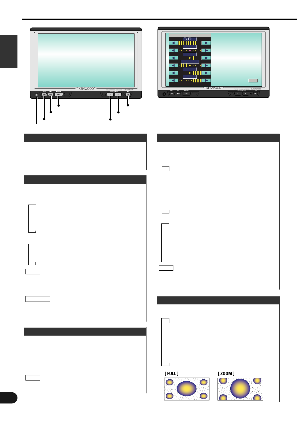
Monitor Control Function
PWR
V.SEL
MODE
–
+
SCRN
English
Phone Jack (Ø3.5)
SCREEN
BRT
TIN
COL
CONT
BLK
DIM
Picture Quality Adjustment Screen
OK
Power
Turning on the power
Press the PWR button.
Turning off the power
Press the PWR button for at least one second.
Switching the Monitor’s Picture
Each time you press the V.SEL button, the monitor’s
picture switches as follows:
●When the Video Box Unit is connected
▼
[VD1]: Video1 picture
▼
[VD2]: Video2 picture
▼
[NAV]: Navigation picture (RGB pictures)
●When the KTC-V800N or KTC-V800P is connected
▼
[TV]: Television picture
▼
[NAV]: Navigation picture (RGB pictures)
NOTE
When connecting KTC-V800N/KTC-V800P, on changing
“AV-IN1” “AV-IN2” settings to “VD” (see Setting the
System, page 6) the switching items become
VIDEO1(“VD1“) and VIDEO2(“VD2“) .
2CAUTION
You cannot view television and video pictures whilst
the vehicle is moving. To enjoy television and video
pictures, find a safe place to park and engage the
parking brake.
Adjusting the Volume
Increasing Volume
Each time you press the + button to increase the
volume.
Decreasing Volume
Each time you press the – button to decrease the
volume.
NOTE
When headphone are connected to the phone jack, no
sound is emitted from the built-in speaker.
4
Switching the Speaker Mode
Each time you press the V.SEL button for at least
one second, the built-in speaker mode switches as
follows:
●When the Video Box Unit is connected
▼
[NORMAL]: Sound with monitor picture
▼
[VIDEO1]: Sound with video1 picture
▼
[VIDEO2]: Sound with video2 picture
▼
[NAV]: Sound with navigation picture
▼
[OFF]: Switch off the built-in speakers
●When the KTC-V800N or KTC-V800P is connected
▼
[NORMAL]: Sound with monitor picture
▼
[TV]: Sound with television picture
▼
[NAV]: Sound with navigation picture
▼
[OFF]: Switch off the built-in speaker
NOTE
When connecting KTC-V800N/KTC-V800P, on changing
“AV-IN1” “AV-IN2” settings to “VD” (see Setting the
System, page 6) the switching items become VIDEO1
and VIDEO2.
Switching the TV/Video Screen Mode
Each time you press the MODE button, the screen
mode switches as follows:
▼
[FULL]: Full picture mode
▼
[ZOOM]: Zoom picture mode
▼
[JUST]: Just picture mode
▼
[CINEMA]: Cinema picture mode
▼
[NORMAL]: Normal picture mode
[ FULL ]
[ ZOOM ]
Page 5
TV1
WD
SEEK BAND
A
UT
O1
SPNORMA
LOV
FUL L
AVNORMA
1
LL
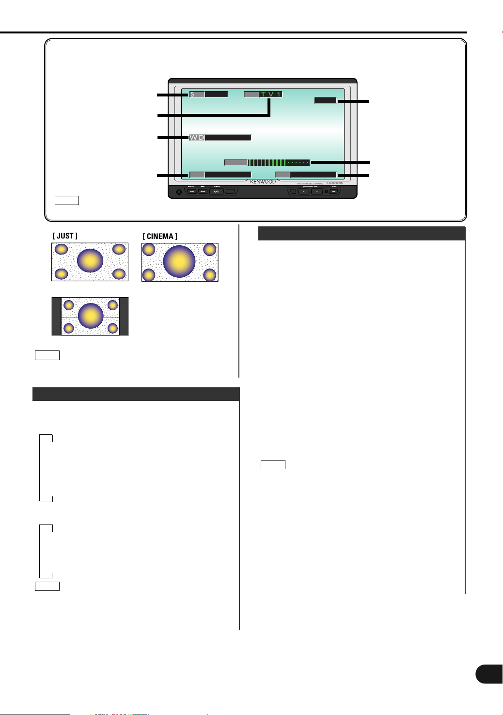
<On Screen Display>
If the monitor's buttons operated while a TV, video or navigation picture is displayed, the receiving
channel No., the picture settings, AV output settings, etc., are superimposed on the picture .
Tuning mode
TV band
Screen mode
Speaker mode
NOTE
Tuning mode,TV band, and Channel No.: When the KTC-V800N/ KTC-V800P is connected.
[ JUST ]
[ CINEMA ]
[ NORMAL ]
NOTE
You cannot operate when the wide picture navigation
is displayed.
Switching the AV Output
Each time you press the PWR button, the AV output
mode switches as follows:
●When the Video Box Unit is connected
▼
[NORMAL]: Picture/sound with monitor picture
▼
[VIDEO1]: Picture/sound with video1
▼
[VIDEO2]: Picture/sound with video2
▼
[NAV]: Sound with navigation
●When the KTC-V800N or KTC-V800P is connected
▼
[NORMAL]: Picture/sound with monitor picture
▼
[TV]: Picture/sound with television
▼
[NAV]: Sound with navigation
NOTE
When connecting KTC-V800N/KTC-V800P,” on
changing “AV-IN1” “AV-IN2” settings to “VD” (see
Setting the System, page 6) the switching items
become VIDEO1 and VIDEO2.
Channel No.
Speaker volume level
AV output mode
Adjusting the Picture Quality
1
Press the SCRN button, the picture quality
adjustment screen to be displayed.
2
Each time you touch [ 3 ]/[ 2 ] to adjust the value.
[BRT] (for Day time screen)
Touch [ 3 ] for a brighter screen.
Touch [ 2 ] for a darker screen.
[TIN]
Touch [ 3 ] for a stronger green level.
Touch [ 2 ] for a stronger red level.
[COL]
Touch [ 3 ] for a deeper color.
Touch [ 2 ] for a paler color.
[CONT]
Touch [ 3 ] for less contrast.
Touch [ 2 ] for stronger contrast.
[BLK]
Touch [ 3 ] for less black level.
Touch [ 2 ] for a stronger black level.
[DIM] (for Night time screen)
Touch [ 3 ] for a brighter screen.
Touch [ 2 ] for a darker screen.
3
Touch [ OK ] to end the picture quality adjustment
screen.
NOTE
•The [ TIN ] and [ COL ] cannot be adjusted for the
navigation screen or the setting screens.
• The [ TIN ] cannot be adjusted for the picture of PAL.
• [BRT] and [DIM] initial values are maximum.
• As regards [DIM] adjustment:
•When the condition is bright around the periphery of
the monitor unit, the brightness does not change
even when [DIM] is adjusted.
•When set to maximum, even if the monitor unit
periphery dims, there is no change in from the
brightness set with [BRT].
• There is no connection with the vehicle’s
illumination switch. (A sensor is installed facing the
front of monitor unit for light detection).
• If you make no key operation for 10 seconds, the
picture quality adjustment screen is automatically
cancelled.
5
Page 6

System Setup Function
PWR
V.SEL
MODE
–
+
SCRN
English
Phone Jack (Ø3.5)
Setting the System
●When the Video Box Unit is connected
1
Press the SCRN button for at least one second to
switch to the setup menu screen.
2
Touch [ SYSTEM ] to switch to the system setting
screen.
NAV
RGB OFF
AV - OUT
NORM
VD1
BEEP
SYS EMT
Setting the Navigation Input Mode [NAV]
Touch [ RGB ], [ VD1 ] or [ VD2 ]. The navigation input
mode will be switched as follows:
[RGB]: When the Navigation unit is connected to the
"RGB" terminal.
[VDI]: When the Navigation unit is connected to the
"AV-INPUT1" terminal.
[OFF]: When the Navigation unit is not connected.
(When the Video Deck is connected to the
"AV-INPUT1" terminal.)
Setting the AV Output Mode [AV-OUT]
Touch [ NORM ], [ NAV ], [ VD1 ] or [ VD2 ]. The
picture/ sound of the AV output mode will be
switched as follows:
[NORM]: Picture/sound with monitor picture
[NAV]: Sound with navigation
[VDI]: Picture/sound with video1
[VD2]: Picture/sound with video2
Setting the Touch Sensor Tone [BEEP]
Touch [ ON ] or [ OFF ] to switch the function on
and off.
[ON]: Touch sensor tone is turned on
[OFF]: Touch sensor tone is turned off
3
Touch [ RTN ] to return to the setup menu screen.
●When the KTC-V800N or KTC-V800P is connected
1
Press the SCRN button for at least one second to
switch to the setup menu screen.
2
Touch [ SYSTEM ] to switch to the system setting
screen-1.
6
VD1
NAV
VD2
OFFON
AV - I N1
VD
AV - I N2
VD OFF
AV - OUT
NORM
VD1
SYS EMT
NAV
TV
VD2
System Setting Screen-1
OFF
NAV
TN
R
Setting the AV Input 1 Mode [AV-IN1]
Touch [ VD ], [ NAV ] or [ OFF ]. The picture/ sound of
the AV input mode will be switched as follows:
[VD]: When the Video Deck is connected to the
"AV-INPUT1" terminal.
TN
R
[NAV]: When the Navigation unit is connected to the
"AV-INPUT1" terminal.
[OFF]: When the "AV-INPUT1" terminal is not used.
Setting the AV Input 2 Mode [AV-IN1]
Touch [ VD ] or [ OFF ]. The picture/ sound of the AV
input mode will be switched as follows:
[VD]: When the Video Deck is connected to the
"AV-INPUT2" terminal.
[OFF]: When the "AV-INPUT2" terminal is not used.
Setting the AV Output Mode [AV-OUT]
Touch [ NORM ], [ TV ], [ NAV ], [ VD1 ] or [ VD2 ].
The picture/ sound of the AV output mode will be
switched as follows:
[NORM]: Picture/sound with monitor picture
[TV]: Picture/sound with television
[NAV]: Sound with navigation
[VDI]: Picture/sound with video1
[VD2]: Picture/sound with video2
NOTE
• No display [VD1] when the "AV-IN1" is set to "OFF".
• No display [VD2] when the "AV-IN2" is set to "OFF".
3
Touch [ 3 ] to switch to the system setting screen-2.
BEEP
SYS EMT
OFFON
TN
R
System Setting Screen-2
Page 7

SYSTEM
SETUP
TOUCH
SYSTEM
TV AREA
TN
R
SETUP
TOUCH
TN
R
Setup Menu Screen < Video Box Unit or KTC-V800N>
Setting the Touch Sensor Tone [BEEP]
Touch [ ON ] or [ OFF ] to switch the function on
and off.
[ON]: Touch sensor tone is turned on
[OFF]: Touch sensor tone is turned off
NOTE
Touch [ 2 ] to return to the system setting screen-1.
4
Touch [ RTN ] to return to the setup menu screen.
Adjusting the Touch Position
The touch panel can be adjusted if the position
touched and the operation performed do not
match.
1
Press the SCRN button for at least one second to
switch to the setup menu screen.
2
Touch [ TOUCH ] to switch to the touch panel
adjustment screen.
TOUCH PANEL ADJUST
Please Touch
the Ce ter of
the Bu ton in
Le f t -Bo t t om Cor ner
3
Accurately touch the mark at the lower left and the
mark at the upper right, following the instructions in
the messages.
When the mark at the upper right is touched, the
adjustment is completed and the system setup menu
screen reappears.
NOTE
• If [ CANCEL ] is touched without touching the button
at the lower left, the adjustment is cancelled and the
screen that was set before switching to the system
setup menu reappears.
•If [ CANCEL ] is touched after touching the button at
the lower left, the button at the lower left reappears.
• If [ RESET ] is touched, the settings are reset to the
factory defaults and the setup menu screen
reappears.
n
tthe
R ESETCANCEL
Setup Menu Screen < KTC-V800P >
Selecting the Reception Area
(When the KTC-V800P is connected)
Select the area for video broadcast viewing.
1
Press the SCRN button for at least one second to
switch to the setup menu screen.
2
Touch [ TV AREA ] to switch to the TV area setting
screen.
1
4 5
PAL-D
PAL-B/G
PAL-I
PAL-B/G
2 3
TN
R
TV1
TV2
C hina•
TV ARE SAET
3
Selecting the Preset Bands
Touch [ TV 1 ] or [ TV 2 ]. The preset band switches
between TV1 and TV2.
4
Selecting the Reception Area
Touch [ 1 ] - [ 5 ] to select the channel setting for
your country as follows:
■ 1
■ 2
China
Singapore
Malaysia
Thailand
Burnei
■ 3
■ 4
■ 5
5
Touch [ RTN ] to return to the setup menu screen.
NOTE
Hong Kong
Indonesia
Australia
The reception area can be set for two separate preset
bands, TV1 and TV2.
7
Page 8

TV Control Function < When The KTC-V800N/KTC-V800P is connected >
O1
UT
SEEK BAND
A
TV1
10
B
English
A
C
D
AME
1P1 3P2 4P3 6P4
8P5 10P6 12P7 47P8
OK
TV picture screen
Switching to the TV Control Screen
1
Press the V.SEL button repeatedly to select the TV
picture.
2
Touch the part C to switch to the TV control screen.
Selecting the Preset Bands
Each time you touch [ BAND ], the preset band
switches between the TV1 and TV2.
Selecting the Tuning Mode
You can choose from three tuning modes: auto
seek, preset station seek, and manual. The
“AUTO1” indicator is displayed when auto seek
tuning is selected, and the “AUTO2” indicator is
displayed when preset station seek tuning is
selected.
Each time you touch [ SEEK ], the mode switches as
follows:
▼
AUTO 1: Auto Seek Tuning
▼
AUTO 2: Preset Station Seek Tuning
▼
MANU: Manual Tuning
Selecting the Channels
Auto Seek Tuning (AUTO1)
Touch [ ¢ ] to seek for channels up the band.
Touch [ 4 ] to seek for channels down the band.
Preset station Seek Tuning (AUTO2)
Touch [ ¢ ] to move to the next preset station (i.e.,
the one with the next highest number).
Touch [ 4 ] to move to the last preset station (i.e.,
the one with the next lowest number).
Manual Tuning (MANU)
Touch [ ¢ ] to increase the channel by one step.
Touch [ 4 ] to decrease the channel by one step.
TV Control Screen
NOTE
You can store 8 stations in each of the TV1 and TV2
preset bands.
Auto Memory Entry
You can automatically store all the receivable
channels in the band currently being listened to,
and then recall them with the touch of a button
later. This function is especially useful when you
are travelling and do not know what stations are
available. Up to 8 stations can be stored this way.
1
Select the preset band for auto memory entry.
2
Touch [ AME ].
[ 4 ] and [ ¢ ] blink.
3
Touch [ 4 ] or [ ¢ ] to start auto memory entry.
The preset station numbers [ P1 ] - [ P8 ] are shown in
order.
When all the stations on a certain band have been
stored in the preset memory, the auto memory entry
stops. The tuner then plays the last station received.
Recalling a Preset Station
Touch the preset station number [ P1 ] - [ P8 ] for the
desired station. The number of the recalled station is
displayed.
Station Preset Memory
Store the channel of the station currently being
listened to. You can then recall that station with a
single touch of a button.
1
Select the station that you want to store.
2
Keep touching the preset station number [ P1 ] - [ P8 ]
8
on which you want to store the station, for two
seconds or more.
Page 9

Selecting the Channels on the TV Picture
Screen
Selecting the Preset Bands
Each time you touch part B, the preset band
switches between the TV1 and TV2.
Selecting the Channels
Auto Seek Tuning (AUTO1)
Touch the part D to seek for channels up the band.
Touch the part A to seek for channels down the
band.
Preset station Seek Tuning (AUTO2)
Touch the part D to move to the next preset station
(i.e., the one with the next highest number).
Touch the part A to move to the last preset station
(i.e., the one with the next lowest number).
Manual Tuning (MANU)
Touch the part D to increase the channel by one
step.
Touch the part A to decrease the channel by one
step.
9
Page 10

Remote Control Function <Provided with the KTC-V800N/KTC-V800P>
2CAUTION
Do not set the remote on hot places such as above the
dashboard.
Loading and Replacing the Batteries
1. Use two "AA" batteries:
English
Slide the cover while pressing downwards to remove it as
illustrated.
2. Insert the batteries with the ª and · poles aligned properly
following the illustration inside the case.
2WARNING
Store unused batteries out of the reach of children. Contact a
doctor immediately if the battery is accidentally swallowed.
NOTE
• The provided batteries are intended for use in operation
checking, and their service life may be short.
• When the remote controllable distance becomes short,
replace both of the batteries with new ones.
Monitor Control Function
• VOL button
Press the 5 button to increase the volume of the built-in speaker.
MODE V.SEL
BAND
4¢
SEARCH
CH. – CH. +
M/S
5
SEEK
AV OUT
VOL
AME SP
∞
Press the ∞ button to decrease the volume of the built-in speaker.
• SP button
Each time you press SP button to switch the built-in speaker mode.
• V.SEL button
Each time you press V.SEL button to switch the monitor's picture.
• MODE button
Each time you press MODE button to switch the screen mode.
• AV OUT button
Each time you press AV OUT button to switch the AV output mode.
(Adjusting the Volume of the built-in speaker- see P.4)
(Switching the Speaker Mode- see P.4)
(Switching the Monitor’s Picture- see P.4)
(Switching the TV/Video Screen Mode- see P.4)
(Switching the AV Output- see P.5)
10
REMOTE CONTROL UNIT
RC-210
TV Control Function
• SEEK button
Each time you press the SEEK button, the tuning mode switches to auto
1, to auto 2 and to manual.
• SEARCH buttons
Press the ¢/CH.+ button to make increasing seeks.
Press the 4/CH.– button to make decreasing seeks.
• BAND button
Each time you press the BAND button, the preset band switches
between the TV1 and TV2.
• AME button
1
Selects the band for auto memory entry.
2
Press the AME button.
3
Press the ¢/CH.+ button or 4/CH.– button to start auto memory entry.
(Selecting the Tuning Mode- see P.8)
(Selecting the Channels- see P.8)
(Selecting the Preset Bands- see P.8)
(Auto Memory Entry- see P.8)
Page 11

Installation
Accessories
External view
......... Number of items
External view
......... Number of items
External view
......... Number of items
1
2
3
........1
........1
........1
4
(Ø4 x 12 mm)
5
(Ø4 x 16 mm)
6
Installation Procedure
1. To prevent short circuits, remove the key from the
ignition and disconnect the · terminal of the battery.
2. Make the proper input and output cable connections for
each unit.
3. Connect the wiring harness cables in the following order:
ground, ignition.
4. Connect the wiring harness connector to the unit.
5. Install the unit in your car.
6. Reconnect the · terminal of the battery.
7. Press the reset button. (See p. 3)
2WARNING
• This video unit is set for rear passenger use only.
Use of this video unit in any front seat and/or
where it may be visible to the driver may be
illegal in some states and may cause driver
distraction and accident which could injure or kill
you.
• This product is intended for use with 12V DC
negative ground power only. Do not connect it to
any other power supply
• To prevent shorting, disconnect the battery cable
from the negative terminal of the battery during
installation.
• Be sure to firmly stabilize this product. Do not install
it in a location which is not stable.
• Follow the installation and wiring procedures
described in this manual. Improper wiring or
modified installation can not only result in
malfunction or damage to the unit but may also
result in an accident.
• Do not install the unit in the following locations.
•A location which interferes with the operation
of the air bag system.
•A location which is not made of plastic.
\ Installing on leather, wood or cloth may damage
the surface.
•A location subject to direct sunlight, subject to the
air from the air conditioner, or subject to moisture
or high temperature.
\This may cause deformation of the monitor unit.
........5
........4
7
8
........2
........2
........4
• Be sure to use the supplied screws for
installation.
Using screws longer than those supplied may
destroy parts inside the unit causing it to smoke.
Using screws shorter than those supplied may
cause the unit to come looks from the installation
bracket.
• If you are not going to install the unit using the
supplied monitor stand, be sure to use a
commercially available monitor stand. (Mounting
holes for such a stand are located on the bottom of
the monitor unit.)
2CAUTION
• If your car's ignition does not come with an ACC
position, connect the ignition cables to a power
source that can be turned on and off with the
ignition key. If you connect the ignition wire to a
power source that receives a constant voltage
supply, as with battery cables, the battery may die.
• If the fuse blows, first make sure that the cables
have not caused a short circuit, then replace the old
fuse with one with the same rating.
• Do not let unconnected cables or terminals touch
metal on the car or anything else conducting
electricity. To prevent short circuits do not remove
the caps from unused terminals or from the ends of
the unconnected cables.
• After the unit is installed, check whether the brake
lamps, blinkers, wipers, etc. on the car are working
properly.
• Insulate unconnected wires with vinyl tape or other
similar material.
• Thoroughly wipe away oil and other dirt from the
installation surface.
Please avoid installation on uneven surfaces.
11
Page 12

Installation
Installation for Monitor Unit
Installation location and cleaning
Select for installation a location where the stand can be
placed completely horizontal or where the front edge of the
support (petal-shaped part) can be attached horizontally as
English
shown in Figure A.
Do not install in locations where the entire support is at a
diagonal such as in Figure B or where the monitor unit is
facing down such as in Figure C.
Thoroughly wipe away and dust or grease from the
installation location using a cloth which has been soaked in
a neutral cleaning agent and wrung out. Attach the stand
after allowing the installation location to dry.
Accessory3
Tighten
Loosen
Tighten
A
1
Bend the stand support to conform to the shape of
the installation location.
2
Adjust the shape of the support so that there is no
rattling or gap when the stand is placed on the
support.
3
Peel off the protective strip from the double-sided
tape on the bottom of the stand and securely attach
the stand.
2CAUTION
• Do not attach the double-sided tape more than once
or touch the adhesive with your fingers as this will
weaken its adhesive strength.
• If the temperature of the surface of the installation
location is low, warm it up using a heater or other
means before attaching the stand. Low
temperature may weaken the adhesive strength of
the tape.
• The supplied stand is specially intended for this
product. Do not use it with another television.
4
Secure the stand using the supplied tapping screw
(Accessory 4).
5
After attaching the stand, allow it to sit undisturbed
for 24 hours.
6
Take care not to apply any force to the stand during
this time.
7
Fully loosen the installation screws, align the slit on
the rear of the unit with the installation shoe and slide
the monitor unit onto the stand.
8
Adjust the height, horizontal angle and vertical angle
of the monitor and securely tighten the installation
screws.
You can also adjust the monitor unit's forward
position by loosening the angle adjustment knobs and
adjusting the angle of the monitor unit's installation
stand.
B
C
12
Loosen
Accessory 4
(Ø4 x 12 mm)
Protective strip
Installation surface
Page 13

Installation for the Video Box Unit
2
AV INPUT AV OUTPUT
1
AV INPUT
PRK SW
FM-TX
–
+
+12V
■ Securing to audio board
Accessory 5
(Ø4 x 16 mm)
Accessory 7
Accessory 6
2CAUTION
Please do not install the unit near the dashboard, the rear tray, or other important components. Doing so could
lead to injury or accident should the unit come off due to a shock and strike a person or an important component.
Tapping screws(Accessory 5) should be used for mounting. (Attachment with velcro strips, although easy, can
come off with a shock.)
■ Securing to pile carpet
Peel the protective strips off of the velcro
strips, attach them to the bottom of the
hideaway unit, and secure to the pile carpet.
Accessory 8
Connecting the Power
Monitor Unit
Accessory 2
Video Box Unit
Connect to the vehicle's parking brake
detection switch harness using the
supplied relay connector.
2 CAUTION
For the sake of safety, be sure to
connect the parking sensor.
Ignition key switch
ACC
Parking sensor wire (Green)
Ignition wire (Red) ª12V
Accessory 1
Fuse (5A)
(Main fuse)
Car fuse box
Battery
Ground wire (Black) · (To car chassis)
13
Page 14

Installation
Connecting the Headphone / AV Equipments
■ Connecting the Headphone
English
Stereo Mini Plug (Ø3.5)
■ Connecting the AV Equipment
Headphone
14
Audio/Visual Output
Audio right output (Red)
•
• Audio left output (White)
• Visual output (Yellow)
Audio/Visual input 2
Audio right intput (Red)
•
•
Audio left intput (White)
• Visual intput (Yellow)
Audio/Visual input 1
Audio right intput (Red)
•
• Audio left intput (White)<Monaural input>
• Visual intput (Yellow)
Page 15

Troubleshooting Guide
What might appear to be a malfunction in your unit may just be the result of slight misoperation or
miswiring. Before calling service, first check the following table for possible problems.
SOLUTIONPOSSIBLE CAUSEPROBLEM
The power does not turn on. The fuse has blown. After checking for short circuits in the cables,
No ACC position on vehicle ignition.
Nothing happens when the
buttons are pressed.
No television/video picture
appears.
(Television picture : when the
KTC-V800N or KTC-V800P is
connected)
The screen is dark. The unit is in a location where temperature is
AM/FM radio reception is poor
and/or there is noise.
(When the KTC-V800N or KTCV800P is connected)
The computer chip in the unit is not
functioning normally.
The unit is not connected to the parking brake
detection switch.
The parking brake is not engaged. For safety reasons no television/video picture
low.
The TV antenna and vehicle‘s radio antenna
are too close.
replace the fuse with one having the same
rating.
Connect the same wire to the ignition as the
battery wire.
Press the reset button on the unit (See page 3).
Make proper connections according to
”Connecting the power“ (See page 13).
are displayed while the vehicle is moving.
Engaging the parking brake will cause picture
to be displayed.
If the temperature of the monitor unit drops,
the screen may appear darker when power is
first turned on due to the characteristics of a
liquid crystal panel. Wait a while after turning
power on for the temperature to rise. Normal
brightness will return.
• Separate the two antennas as far as possible.
• Turn off the LZ-800W.
15
Page 16

Specifications
Specifications subject to change without notice.
Monitor Unit
Screen size ..................................................................................................................8.0 inches wide
English
Display system ............................................................................................Transparent TN LCD panel
Drive system..................................................................................................TFT active matrix system
Number of pixels ........................................................................336.960 pixels (480 H x 234 V x RGB)
Effective pixels..........................................................................................................................99.99%
Pixel arrangement..........................................................................................RGB striped arrangement
Back lighting ............................................................................................................Cold cathode tube
Phone jack (Miniplug x 1) Audio output level........................................Stereo Mini Jack / 820 mV/32 Ω
Built-in speaker ..........................................................................................................1W (40 x 20 mm)
Video Box Unit
Color system ....................................................................................................NTSC/PAL(Compatible)
Video input level (RCA jack) ..............................................................................................1 Vp-p/75 Ω
Audio input level (RCA jack) ..................................................................................................1 V/22 KΩ
Video output level (RCA jack) ..............................................................................................1 Vp-p/75 Ω
Audio output level (RCA jack)............................................................................................500 mV/1 KΩ
RGB Input (13 Pin) ..........................................................................................................0.7 Vp-p/75 Ω
General
Operating voltage ..............................................................................................14.4 V DC (11 to 16 V)
Consumed Power ......................................................................27 W (25 W:during normal operations)
Operational temperature range ....................................................................................–10°C to +60°C
Storage temperature range ..........................................................................................–30°C to +85°C
Size
(Monitor unit) ........................................................................................211.3(W) x 134(H) x 30(D) mm
(Video box unit) ......................................................................................188(W) x 30(H) x 144.8(D) mm
Mass
(Monitor unit) ................................................................................................................580 g (1.3 LBS)
(Video box unit) ............................................................................................................730 g (1.6 LBS)
176.4(W) x 99.2(H) x 202(Diagonal) mm
6-15/16(W) x 3-7/8(H) inch
8-5/16(W) x 5-1/4 (H) x 1-3/16(D) inch
7-3/8(W) x 1-3/16(H) x 5-11/16(D) inch
16
Although the effective pixels for the liquid crystal panel is given as 99.99% or more, 0.01% of pixels may not light or
may light incorrectly.
 Loading...