

Page 1

LZ-701W
7-inch WIDE SCREEN MONITOR
INSTRUCTION MANUAL
MONITEUR GRAND ECRAN 7 pouces
MODE D’EMPLOI
7-Zoll BREITBILD MONITOR
BEDIENUNGSANLEITUNG
7 inch BREEDBEELDMONITOR
GEBRUIKSAANWIJZING
MONITOR A SCHERMO AMPIO 7 pollici
ISTRUZIONI PER L’USO
MONITOR DE PANTALLA PANORÁMICA DE 7 pulgadas
MANUAL DE INSTRUCCIONES
MONITOR DE ECRÃ LARGO de 7 polegadas
MANUAL DE INSTRUÇÕES
© PRINTED IN JAPAN B64-1932-00+ (E)
LA DICHIARAZIONE DI CONFORMITA' "CE"
DI QUESTO PRODOTTO E' DEPOSITATA
PRESSO:
KENWOOD ELECTRONICS EUROPE B.V.
AMSTERDAMSEWEG 37
1422 AC UITHOORN
THE NETHERLANDS
Page 2

Contents
Safety Precautions. . . . . . . . . . . . . . . . . . . . . . . . . . . . . . . . . . . 3
Operation
English
Power . . . . . . . . . . . . . . . . . . . . . . . . . . . . . . . . . . . . . . . . . . . . . . . . . . . . . . . . . . . . .4
Switching the Monitor’s Picture . . . . . . . . . . . . . . . . . . . . . . . . . . . . . . . . . . . . . . . . .4
Switching the Screen Mode <When the KTC-V800N/V800P is connected> . . . . . . . .4
Adjusting the Picture Quality . . . . . . . . . . . . . . . . . . . . . . . . . . . . . . . . . . . . . . . . . . .5
Selecting the Channels <When the KTC-V800N/V800P is connected> . . . . . . . . . . .6
Setting the Function
Selecting the Preset Bands <When the KTC-V800N/V800P is connected> . . . . . . . . .6
Selecting the Seek Mode <When the KTC-V800N/V800P is connected> . . . . . . . . . . .7
Station Preset Memory <When the KTC-V800N/V800P is connected> . . . . . . . . . . . .7
Selecting the Reception Area <When the KTC-V800P is connected> . . . . . . . . . . . . .7
Setting the Remote Sensor On/Off . . . . . . . . . . . . . . . . . . . . . . . . . . . . . . . . . . . . . . .8
FM Transmitter Function <When the KTC-V800N/V800P is connected> . . . . . . . . . . .8
Switching the AV Output <When the KTC-V800N/V800P is connected> . . . . . . . . . . .8
Remote Control Function <Provided with the KTC-V800N/V800P> . . . . . . . . 9
Installation
Accessories . . . . . . . . . . . . . . . . . . . . . . . . . . . . . . . . . . . . . . . . . . . . . . . . . . . . . . . .10
Installation Procedure . . . . . . . . . . . . . . . . . . . . . . . . . . . . . . . . . . . . . . . . . . . . . . . .10
Installation for Monitor Unit . . . . . . . . . . . . . . . . . . . . . . . . . . . . . . . . . . . . . . . . . . .11
Installation for the Video Box Unit . . . . . . . . . . . . . . . . . . . . . . . . . . . . . . . . . . . . . .14
Connection . . . . . . . . . . . . . . . . . . . . . . . . . . . . . . . . . . . . . . . . . . . . . . . . . . . . . . . .15
Troubleshooting Guide . . . . . . . . . . . . . . . . . . . . . . . . . . . . . . . 16
Specifications . . . . . . . . . . . . . . . . . . . . . . . . . . . . . . . . . . . . . 17
2
The control screens shown in this manual are for explanation purposes
only. The actual screens and design differ.
Page 3
Safety Precautions
2WARNING
To prevent injury and/or fire, take the following precautions:
•Ensure that the unit is securely installed. Otherwise it may fly out of place during
collisions and other jolts.
•When extending the ignition or ground wires, make sure to use automotive-grade
wires or other wires with an area of 0.75mm
deterioration and damage to the wire coating.
•To prevent short circuits, never put or leave any metallic objects (e.g., coins or metal
tools) inside the unit.
•If the unit starts to emit smoke or strange smells, turn off the power immediately
and consult your Kenwood dealer
•Be careful not to drop the unit or subject it to strong shock.
The unit may break or crack because it contains glass parts.
•Do not touch the liquid crystal fluid if the LCD is damaged or broken due to shock.
The liquid crystal fluid may be dangerous to your health or even fatal.
If the liquid crystal fluid from the LCD contacts your body or clothing, wash it off
with soap immediately.
2CAUTION
To prevent damage to the machine, take the following precautions:
•Make sure to ground the unit to a negative 12V DC power supply.
•Do not open the back covers of the unit.
•Do not install the unit in a spot exposed to direct sunlight or excessive heat or
humidity. Also avoid places with too much dust or the possibility of water splashing.
•Do not subject the monitor unit to excessive shock, as it is a piece of precision
equipment.
•When replacing a fuse, only use a new one with the prescribed rating. Using a fuse
with the wrong rating may cause your unit to malfunction.
•To prevent short circuits when replacing a fuse, first disconnect the wiring harness.
•Do not use any screws except for the ones provided. The use of improper screws
might result in damage to the main unit.
•You cannot view TV/ video pictures whilst the vehicle is moving. To enjoy TV/ video
pictures, find a safe place to park and engage the parking brake.
2
(AWG18) or more to prevent wire
NOTE
•If you experience problems during installation, consult your Kenwood dealer.
•If the unit does not seem to be working right, try pressing the reset button first. If
that does not solve the problem, consult your Kenwood dealer.
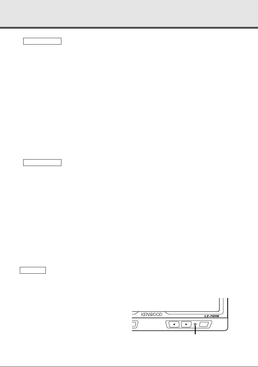
7.0-inch WIDE COLOR LCD MONITOR
Reset button
3
Page 4
Operation
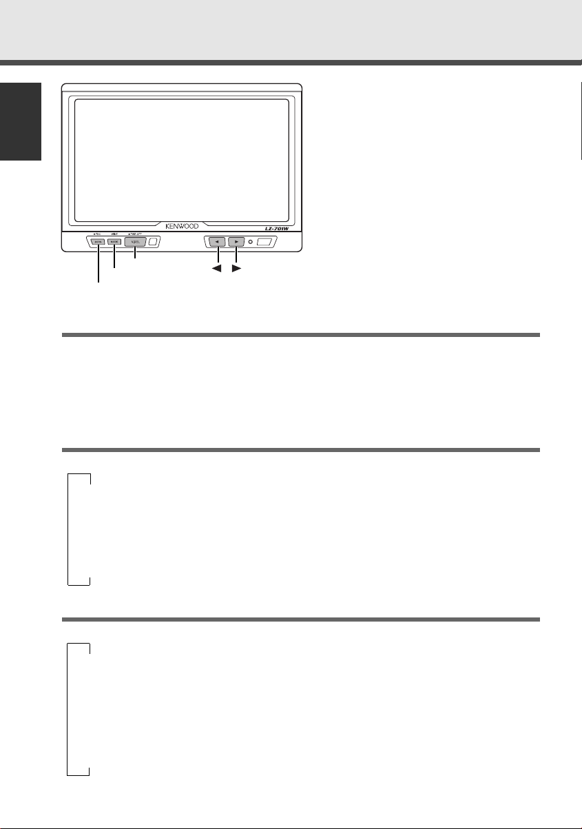
7.0-inch WIDE COLOR LCD MONITOR
SCRN
MODE
V.SEL
English
Power
Turning on the power
Press the V.SEL button.
Turning off the power
Press the V.SEL button for at least two seconds.
Switching the Monitor’s Picture
<When the KTC-V800N or KTC-V800P is connected>
Each time you press the V.SEL button, the monitor’s picture switches as follows:
∞
[TV]: Television picture
∞
[NAV]: Navigation picture (RGB picture)
∞
[VIDEO1]: Video 1 picture (AV-IN1)
∞
[VIDEO2]: Video 2 picture (AV-IN2)
Switching the Screen Mode
Each time you press the MODE button, the screen mode switches as follows:
∞
[FULL]: Full picture mode
∞
[ZOOM]: Zoom picture mode
∞
[JUST]: Just picture mode
∞
[CINEMA]: Cinema picture mode
4
∞
[NORMAL]: Normal picture mode
Page 5
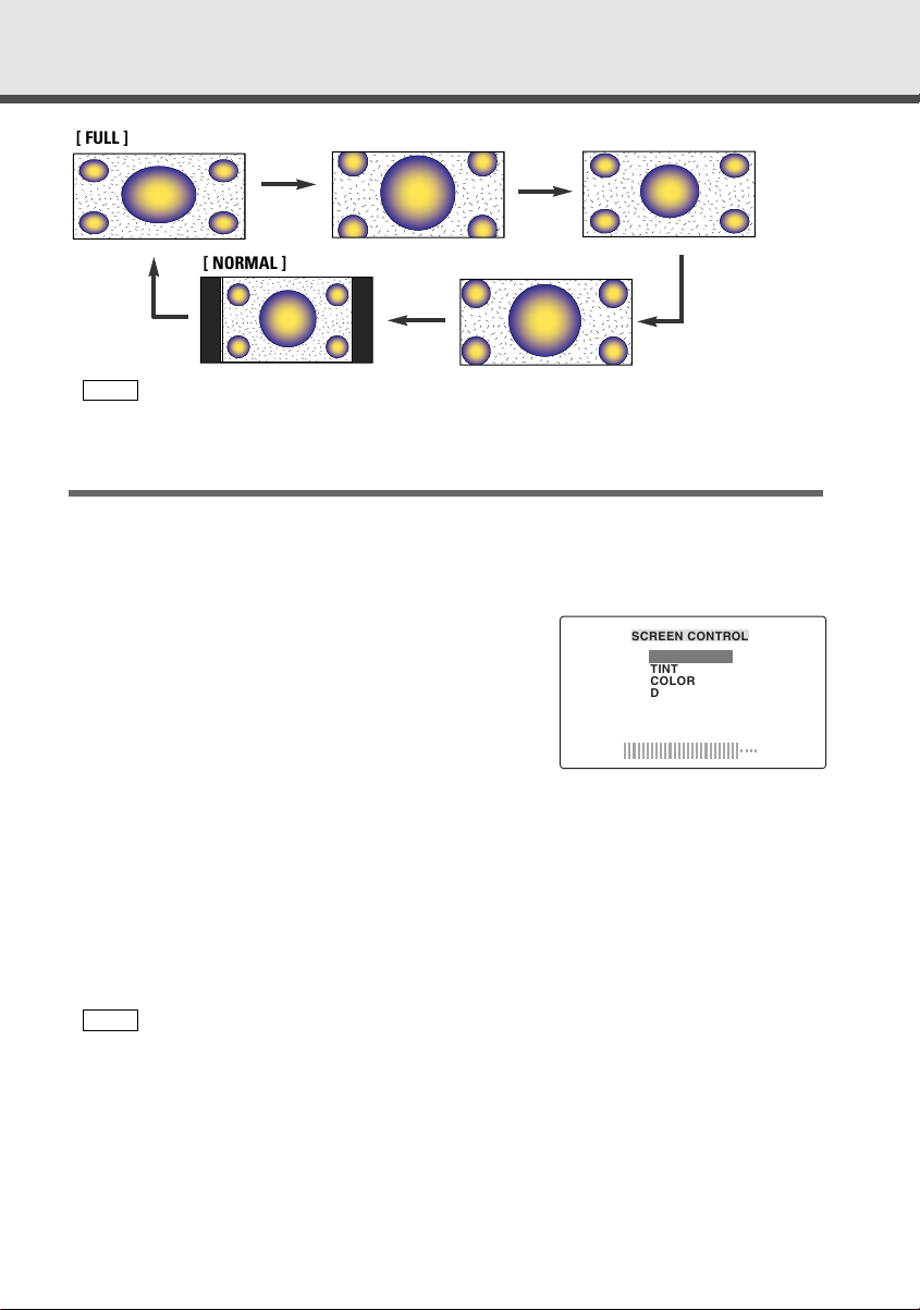
[ FULL ]
[ ZOOM ]
[ JUST ]
[ NORMAL ]
NOTE
You cannot operate when the navigation picture is displayed.
<When the KTC-V800N or KTC-V800P is connected>
[ CINEMA ]
Adjusting the Picture Quality
1
Press the SCRN button, the picture quality adjustment screen to be displayed.
2
Each time you press the SCRN button, the adjustment item can be selected..
3
Press the [ 2 ] or [ 3 ] button to adjust the value.
[BRIGHTNESS] (for Day time screen)
Press the [ 3 ] button for a brighter screen.
Press the [ 2 ] button for a darker screen.
[TINT]
Press the [ 3 ] button for a stronger green level.
Press the [ 2 ] button for a stronger red level.
[COLOR]
Press the [ 3 ] button for a deeper color.
Press the [ 2 ] button for a paler color.
[DIMMER] (for Night time screen)
Press the [ 3 ] button for a brighter screen.
Press the [ 2 ] button for a darker screen.
[CONTRAST]
Press the [ 3 ] button for stronger contrast.
Press the [ 2 ] button for less contrast.
[BLACK LEVEL]
Press the [ 3 ] button for less black level.
Press the [ 2 ] button for a stronger black level.
NOTE
• The [ TINT ] cannot be adjusted for the picture of PAL.
• The [ TINT ] and [ COLOR ] cannot be adjusted for the navigation picture.
• [BRIGHTNESS] and [DIMMER] initial values are maximum.
• As regards [DIMMER] adjustment:
• When the condition is bright around the periphery of the monitor unit, the brightness does
not change even when [DIMMER] is adjusted.
• When set to maximum, even if the monitor unit periphery dims, there is no change in from
the brightness set with [BRIGHTNESS].
• There is no connection with the vehicle’s illumination switch. (A sensor is installed facing the
front of monitor unit for light detection).
• If you make no key operation for 10 seconds, the picture quality adjustment screen is
automatically cancelled.
SCREEN CONTROL
BRIGHTNESS
TINT
COLOR
DIMMER
CONTRAST
BLACK LEVEL
-
+
5
Page 6
Operation
7.0-inch WIDE COLOR LCD MONITOR
SCRN
MODE
V.SEL
English
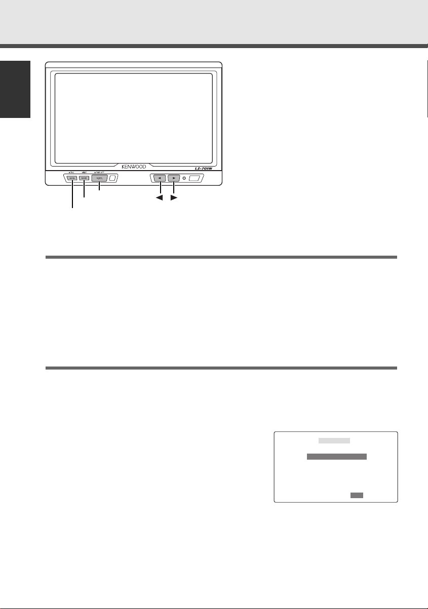
Selecting the Channels
<When the KTC-V800N or KTC-V800P is connected>
Auto Seek Mode (AUTO1)
Press the [ 3 ] button to seek for channels up the band.
Press the [ 2 ] button to seek for channels down the band.
Preset Station Seek Mode (AUTO2)
Press the [ 3 ] button to move to the next preset station.
Press the [ 2 ] button to move to the last preset station.
Manual Seek Mode (MANU)
Press the [ 3 ] button to increase the channel by one step.
Press the [ 2 ] button to decrease the channel by one step.
Setting the Function
1
Press the SCRN button for at least two second, the function setting screen to be
displayed.
2
Each time you press the SCRN button, the setting item can be selected.
3
Press the [ 2 ] or [ 3 ] button to set the function.
Selecting the Preset Bands [TV BAND]
<When the KTC-V800N or KTC-V800P is connected>
Press the [ 2 ] or [ 3 ] button to switch to the preset
band TV1 and TV2.
6
FUNCTION
TV BAND TV2
SEEK MODE AUTO1
3
3
TV2TV1
5
Page 7

Selecting the Seek Mode [SEEK MODE]
<When the KTC-V800N or KTC-V800P is connected>
You can choose from three seek modes: auto seek,
preset station seek, and manual seek.
Press the [ 2 ] or [ 3 ] button, the mode switches as
follows:
[AUTO 1]: Auto Seek Mode
5
∞
[AUTO 2]: Preset Station Seek Mode
5
∞
[MANU]: Manual Seek Mode
FUNCTION
TV BAND TV2
SEEK MODE AUTO1
3
3
MANUAUTO1 AUTO2
5
Channel Preset Memory [USER PRESET MEMORY]
<When the KTC-V800N or KTC-V800P is connected>
Store the channel of the station currently being
looked to.
1
Press the [ 2 ] or [ 3 ] button to select the [ P1 ] [ P8 ].
2
Press the SCRN button for at least two seconds to
store the channel of the station currently.
NOTE
You can store 8 stations in each of the TV1 and TV2 preset
bands.
Selecting the Reception Area [TV AREA]
<When the KTC-V800P is connected>
Press the [ 2 ] or [ 3 ] button to select the channel
setting for your country as follows:
1
2
China
Singapore
PAL-D
PAL-B/G
Malaysia
Thailand
Brunei
3
4
5
Hong Kong
Indonesia
Australia
PAL-I
PAL-B/G
FUNCTION
USER PRESET MEMORY
3
3
P1 2 P2 3 P3 4 P4 6P2 3 P3 4
P6 9P5 7 P7 10 P8 12
FUNCTION
TV AREA TV1
3
3
245
1 3
China
5
NOTE
The reception area can be set for two separate preset
bands, TV1 and TV2.
7
Page 8

Operation
7.0-inch WIDE COLOR LCD MONITOR
SCRN
MODE
V.SEL
English
Setting the Remote Sensor On/Off [REMOTE]
If this unit also runs when operating other units with
different Kenwood remote controls, its remote
control function can be turned off.
Press the [ 2 ] or [ 3 ] button to switch the function
on and off.
FM Transmitter Function [FM-TX]
<When the KTC-V800N* or KTC-V800P is connected>
You can use the FM transmitter function to hear the
sound of the TV, video from your car FM radio.
Press the [ 2 ] or [ 3 ] button to change the frequency
by 0.1 MHz step and off [OFF].
NOTE
• *The KTC-V800N is not display the FM transmitter function
depending on the sales area.
• Be sure to select a frequency that is not the same as a
broadcast station in your area.
• The auto seek function on your car radio may not stop at
the FM transmitter frequency. In this case, use the manual
seek function to set the radio to the FM transmitter
frequency.
Switching the AV Output [AV-OUT]
<When the KTC-V800N or KTC-V800P is connected>
Press the [ 2 ] or [ 3 ] button, the AV output mode
switches as follows:
▼
[NORMAL](NOR): Picture/sound with monitor picture
▼
[TV]: Television picture/sound
▼
[VIDEO1](VD1): Video 1 picture/sound
▼
[VIDEO2](VD2): Video 2 picture/sound
FUNCTION
REMOTE OFF
FM-TX 87.5MHz
AV-OUT NORMAL
3
3
OFFON
FUNCTION
REMOTE OFF
FM-TX 87.5MHz
AV-OUT NORMAL
3
3
87.5
FUNCTION
REMOTE OFF
FM-TX 87.5MHz
AV-OUT VIDEO1
3
3
VD1NOR TV VD2
8
Page 9

Remote Control Function
<Provided with the KTC-V800N/KTC-V800P>
2CAUTION
Do not set the remote on hot places such as above the
dashboard.
Loading and Replacing the Batteries
1. Use two "AA" batteries:
Slide the cover while pressing downwards to remove it
as illustrated.
2. Insert the batteries with the ª and · poles aligned
properly following the illustration inside the case.
2WARNING
Store unused batteries out of the reach of children. Contact
a doctor immediately if the battery is accidentally swallowed.
NOTE
•The provided batteries are intended for use in operation checking, and their service life may
be short.
• When the remote controllable distance becomes short, replace both of the batteries with
new ones.
Monitor Control Function
•V.SEL button
Each time you press V.SEL button to switch the monitor's picture.
• MODE button
MODE V.SEL
BAND
4¢
SEARCH
CH. – CH. +
M/S
5
SEEK
AV OUT
VOL
AME SP
REMOTE CONTROL UNIT
∞
RC-210
Each time you press MODE button to switch the screen mode.
•AV OUT button
Each time you press AV OUT button to switch the AV output
mode.
TV Control Function
• BAND button
Each time you press the BAND button, the preset band
switches between the TV1 and TV2.
• SEARCH buttons
Press the ¢/CH.+ button to make increasing seeks.
Press the 4/CH.– button to make decreasing seeks.
• SEEK button
Each time you press the SEEK button, the seek mode switches
to auto 1, to auto 2 and to manual.
• AME button
You can automatically store all the receivable channels in the
band currently being looked to.
1
Select the band for auto memory entry.
2
Press the AME button.
3
Press the ¢/CH.+ button to start auto memory entry.
9
Page 10

Installation
Accessories
External view
English
1
......... Number of items
........1
External view
4
......... Number of items
(Ø4 x 12 mm)
........5
2
3
........1
........1
5
(Ø4 x 16 mm)
........2
Installation Procedure
1. To prevent short circuits, remove the key from the ignition and disconnect the · terminal of
the battery.
2. Make the proper input and output wire connections for each unit.
3. Connect the wiring harness wires in the following order: ground, ignition.
4. Connect the wiring harness connector to the unit.
5. Install the unit in your car.
6. Reconnect the · terminal of the battery.
7. Press the reset button. (See p. 3)
2WARNING
•This product is intended for use with 12V DC negative ground power only. Do not
connect it to any other power supply
•To prevent shorting, disconnect the battery wire from the negative terminal of the
battery during installation.
•Be sure to firmly stabilize this product. Do not install it in a location which is not
stable.
•Follow the installation and wiring procedures described in this manual. Improper
wiring or modified installation can not only result in malfunction or damage to the
unit but may also result in an accident.
•Do not install the unit in the following locations.
•A location which interferes with the operation of the air bag system.
•A location which is not made of plastic.
\ Installing on leather, wood or cloth may damage the surface.
•A location subject to direct sunlight, subject to the air from the air conditioner, or
subject to moisture or high temperature.
\This may cause deformation of the monitor unit.
10
Page 11

•Be sure to use the supplied screws for installation.
Using screws longer than those supplied may destroy parts inside the unit causing it
to smoke. Using screws shorter than those supplied may cause the unit to come
looks from the installation bracket.
•If you are not going to install the unit using the supplied monitor stand, be sure to
use a commercially available monitor stand. (Mounting holes for such a stand are
located on the bottom of the monitor unit.)
2CAUTION
• If your car's ignition does not come with an ACC position, connect the ignition
wires to a power source that can be turned on and off with the ignition key. If you
connect the ignition wire to a power source that receives a constant voltage supply,
as with battery wires, the battery may die.
• If the fuse blows, first make sure that the wires have not caused a short circuit,
then replace the old fuse with one with the same rating.
• Do not let unconnected wires or terminals touch metal on the car or anything else
conducting electricity. To prevent short circuits do not remove the caps from unused
terminals or from the ends of the unconnected wires.
•After the unit is installed, check whether the brake lamps, blinkers, wipers, etc. on
the car are working properly.
•Insulate unconnected wires with vinyl tape or other similar material.
•Thoroughly wipe away and dust or grease from the installation location using a cloth
which has been soaked in a neutral cleaning agent and wrung out. Attach the stand
after allowing the installation location to dry.
11
Page 12

Installation
;;;;;;;;;;;
;;;;;;;;;;;
;;;;;;;;;;;
;;;;;;;;;;;
;;;;;;;;;;;
;;;;;;;;;;;
;;;;;;;;;;;
;;;;;;;;;;;
;;;;;;;;;;;
;;;;;;;;
;;;;;;;;
;;;;;;;;
;;;;;;;;
;;;;;;;;
;;;;;;;;
;;;;;;;;
;;;;;;;;
Installation for Monitor Unit
Installation location and cleaning
Select for installation a location where the stand can be placed completely horizontal or
English
where the front edge of the support (petal-shaped part) can be attached horizontally as
shown in Figure A.
Do not install in locations where the entire support is at a diagonal such as in Figure B or
where the monitor unit is facing down such as in Figure C.
2CAUTION
Thoroughly wipe away and dust or grease
from the installation location using a cloth
which has been soaked in a neutral cleaning
A
agent and wrung out. Attach the stand after
allowing the installation location to dry.
1
Bend the stand support to conform to the shape of the installation location.
2
Adjust the shape of the support so that there is no rattling or gap when the stand is
placed on the support.
3
Peel off the protective strip from the double-sided tape on the bottom of the stand and
securely attach the stand.
2CAUTION
• Do not attach the double-sided tape more than once or touch the adhesive with your
fingers as this will weaken its adhesive strength.
• If the temperature of the surface of the installation location is low, warm it up using a
heater or other means before attaching the stand. Low temperature may weaken the
adhesive strength of the tape.
• The supplied stand is specially intended for this product. Do not use it with another
television.
4
Secure the stand using the supplied tapping screw (Accessory 4).
5
After attaching the stand, allow it to sit undisturbed for 24 hours.
6
Take care not to apply any force to the stand during this time.
7
Fully loosen the installation screws, align the slit on the rear of the unit with the
installation shoe and slide the monitor unit onto the stand.
8
Adjust the height, horizontal angle and vertical angle of the monitor and securely tighten
the installation screws.
You can also adjust the monitor unit's forward position by loosening the angle
adjustment knobs and adjusting the angle of the monitor unit's installation stand.
B
C
12
Page 13

Tighten
Loosen
Tighten
Loosen
Accessory 4
(Ø4 x 12 mm)
Accessory 3
Protective strip
Installation surface
13
Page 14

Installation
Installation for the Video Box Unit
Accessory 5 (Ø4 x 16 mm)
English
14
Page 15

Connection
KTC-V800N/KTC-V800P
Accessory 1
2
+12 V
AV INPUT AV OUTPUT
AV INPUTANTENNA
1
Monitor Unit
Accessory 2
Video Box Unit
TO MONITOR UNIT VIDEO IN VIDEO OUT POWER
Accessory 2
Visual input
2 CAUTION
For the sake of safety, be sure to connect the
parking sensor.
Parking sensor wire (Green)
Ignition key switch
–
+
Car fuse box (Main fuse)
Battery
PRK SW
ACC
Ignition wire (Red) ª12V
ACC
Ground wire (Black) · (To car chassis)
Visual Output
Accessory 1
Fuse (5A)
FM TX
15
Page 16

Troubleshooting Guide
What might appear to be a malfunction in your unit may just be the result of
slight misoperation or miswiring. Before calling service, first check the
following table for possible problems.
English
The power does not turn on. The fuse has blown. After checking for short circuits
No ACC position on vehicle
ignition.
Nothing happens when the
buttons are pressed.
No television/video picture
appears.
(Television picture : when the
KTC-V800N or KTC-V800P is
connected)
The screen is dark. The unit is in a location where
AM/FM radio reception is poor
and/or there is noise.
(When the KTC-V800N or KTCV800P is connected)
The computer chip in the unit is
not functioning normally.
The unit is not connected to the
parking brake detection switch.
The parking brake is not
engaged.
temperature is low.
The TV antenna and vehicle‘s
radio antenna are too close.
in the wires, replace the fuse
with one having the same rating.
Connect the same wire to the
ignition as the battery wire.
Press the reset button on the unit
(See page 3).
Make proper connections
according to ”Connection“ (See
page 15).
For safety reasons no video
picture are displayed while the
vehicle is moving. Engaging the
parking brake will cause picture
to be displayed.
If the temperature of the monitor
unit drops, the screen may
appear darker when power is first
turned on due to the
characteristics of a liquid crystal
panel. Wait a while after turning
power on for the temperature to
rise. Normal brightness will
return.
• Separate the two antennas as
• Turn off the LZ-701W.
SOLUTIONPOSSIBLE CAUSEPROBLEM
far as possible.
16
Page 17

Specifications
Specifications subject to change without notice.
Monitor Unit
Screen size....................................................................................7.0 inches wide
Display system..............................................................Transparent TN LCD panel
Drive system ..................................................................TFT active matrix system
Number of pixels ........................................336,960 pixels (480 H x 234 V x RGB)
Effective pixels ..........................................................................................99.99%
Pixel arrangement ..........................................................RGB striped arrangement
Back lighting ..............................................................................Cold cathode tube
Video Box Unit
Color system ....................................................................NTSC/PAL(Compatible)
Video input level ................................................................................1 Vp-p/75 Ω
Video output level ..............................................................................1 Vp-p/75 Ω
General
Operating voltage................................................................14.4 V DC (11 to 16 V)
Consumed Power ..........................................................................................11 W
Operational temperature range......................................................–10°C to +60°C
Storage temperature range............................................................–30°C to +85°C
Size
(Monitor unit) ............................................................176(W) x 123(H) x 29(D) mm
(Video box unit) ..........................................................100(W) x 25(H) x 50(D) mm
Mass
(Monitor unit) ................................................................................420 g (0.9 LBS)
(Video box unit)..............................................................................170 g (0.4 LBS)
154.1(W) x 87.05(H) x 177(Diagonal) mm
6-1/16(W) x 3-7/16(H) inch
6-15/16(W) x 4-13/16 (H) x 1-1/8(D) inch
3-15/16(W) x 1(H) x 1-15/16(D) inch
Although the effective pixels for the liquid crystal panel is given as 99.99% or more, 0.01% of
pixels may not light or may light incorrectly.
17
Page 18

 Loading...