

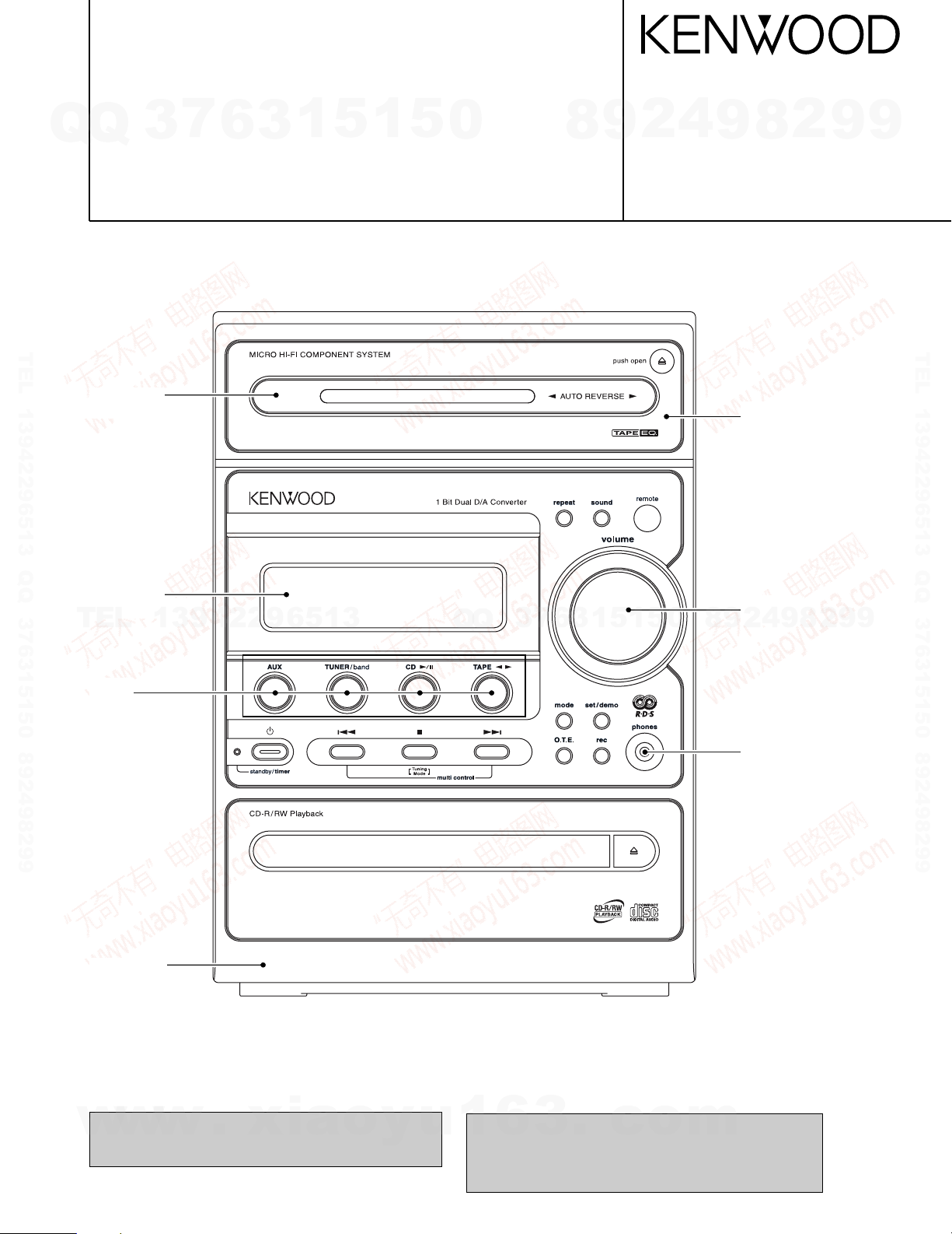
MICRO HI-FI COMPONENT SYSTEM
RXD-M66-H/M66-N/M66-S
Q
Q
7
3
LS-M66-H/M66-N/M66-S/M66IT-H/M66IT-S
6
3
1
5
1
5
0
SERVICE MANUAL
(HM-636/636IT)
TEL 13942296513 QQ 376315150 892498299
Front glass *
(B10-)
8
4
2
9
© 2003-5 PRINTED IN KOREA
B51-5855-00 (K/K) 353
9
Cassette lid *
(A53-)
8
2
9
9
TEL 13942296513 QQ 376315150 892498299
Front glass *
(B10-)
TEL
Knob *
(K29-)
Panel ass'y *
(A60-)
13942296513
Q
Q
3
7
6
3
1
5
1
5
0
Knob *
(K29-)
4
2
9
8
Miniature Phone jack
(E11-0399-05)
9
8
2
9
9
In compliance with Federal Regulations, following are repro-
w
w
duction of labels on, or inside the product relating to laser
product safety.
w
.
xia
o
y
u
* Refer to parts list on page 21.
KENWOOD-Corp. certifies this equipment conforms to DHHS
1
6
3
.
c
o
Regulations No.21 CFR 1040. 10, Chapter 1, subchapter J.
DANGER : Laser radiation when open and interlock defeated.
AVOID DIRECT EXPOSURE TO BEAM.
m
RXD-M66/LS-M66
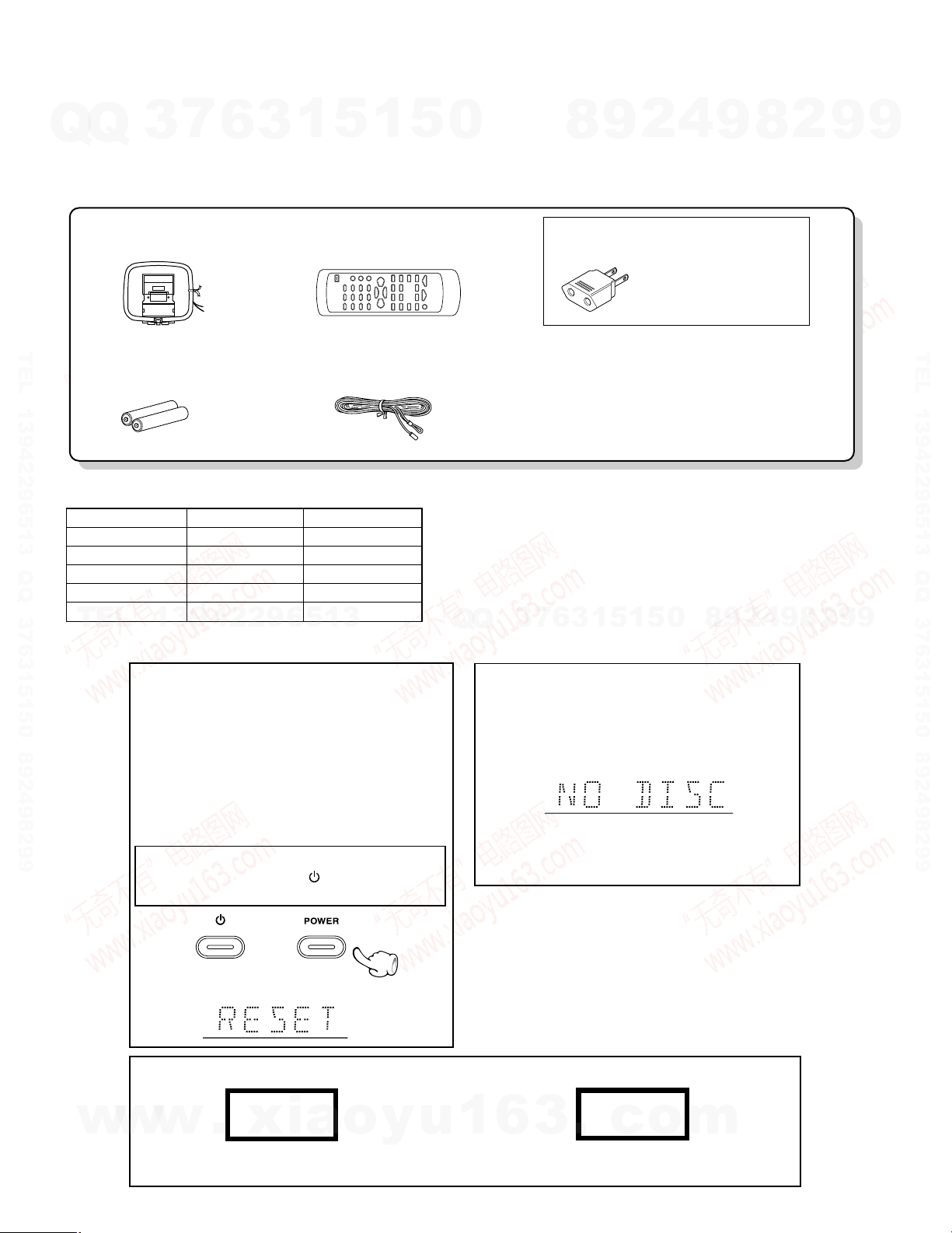
FM indoor antenna (1)
(T90-0877-05)
AM loop antenna (1)
(T90-0893-05)
Remote control unit (1)
(A70-1568-05): EE1E2
(A70-1569-05): M1X1X2
Batteries (R6/AA) (2)
Use to adapt the plug on the
power cord to the shape of the
wall outlet.
(Accessory only for regions where
use is necessary.)
AC Plug Adaptor (1)
(E03-0115-05)
The marking of products using lasers (For countries other than U.S.A., U.S.-Military and Canada)
The marking of this product has been classified as Class 1. It means
that there is no danger of hazardous radiation outside the product.
Location: Back panel
CLASS 1
LASER PRODUCT
CAUTION
VISIBLE LASER RADIATION
WHEN OPEN. DO NOT STARE
INTO BEAM OR VIEW DIRECTLY
WITH OPTICAL INSTRUMENTS.
Inside this laser product, a laser diode classified as Class 3A laser
radiation is contained as alerted by the internal caution label shown
above. Do not stare into beam or view directly with optical instruments.
1 Remove the CD from the unit.
2 Press the CD 6 key.
3 Wait for some time and verify that the display
appears as above.
4 Wait a few seconds and turn the unit OFF.
Note related to transportation and movement
Before transporting or moving this unit, carry out the following operations.
Operation to reset
The microcomputer may fall into malfunction (impossibility to operate, erroneous display, etc.) when the power
cord is unplugged while unit is ON or due to an external
factor. In this case, execute the following procedure to
reset the microcomputer and return it to normal condition.
Unplug the power cord from the power outlet, then
while holding the POWER or
key depressed, plug
the power cord again.
÷ Please note that resetting the microcomputer clears
the contents stored in and it returns to conditio n
when it left the factory.
or
After resetting the microcomputer, the display will show
as follow:
ACCESSORIES / CAUTIONS
Attention
Q
Q
Please contact our KENWOOD Service Department in your side if you want the service information; Circuit Description. Full
Described Parts list and so. Information is available to you by internet from us. On circuit description, refer to RXD-M55.
Accessories
TEL 13942296513 QQ 376315150 892498299
System Configurations
SYSTEM RECEIVER SPEAKER
HM-636-H RXD-M66-H LS-M66-H
HM-636-N RXD-M66-N LS-M66-N
HM-636-S RXD-M66-S LS-M66-S
HM-636IT-H RXD-M66-H LS-M66IT-H
HM-636IT-S RXD-M66-S LS-M66IT-S
TEL
3
7
6
3
1
13942296513
5
1
5
0
Q
Q
3
7
6
8
3
9
1
5
1
2
5
4
0
9
8
9
8
2
4
2
9
8
9
2
9
9
TEL 13942296513 QQ 376315150 892498299
9
Cautions
2
w
w
w
.
xia
o
y
u
1
6
3
.
c
o
m
RXD-M66/LS-M66
DIGITAL
OUT
OPTICAL
AUX
INPUT
L
R
GND
AM
ANTENNA
FRONT
SPEAKERS
(6-16
Ω)
L
-
+
R
FM
75
Ω
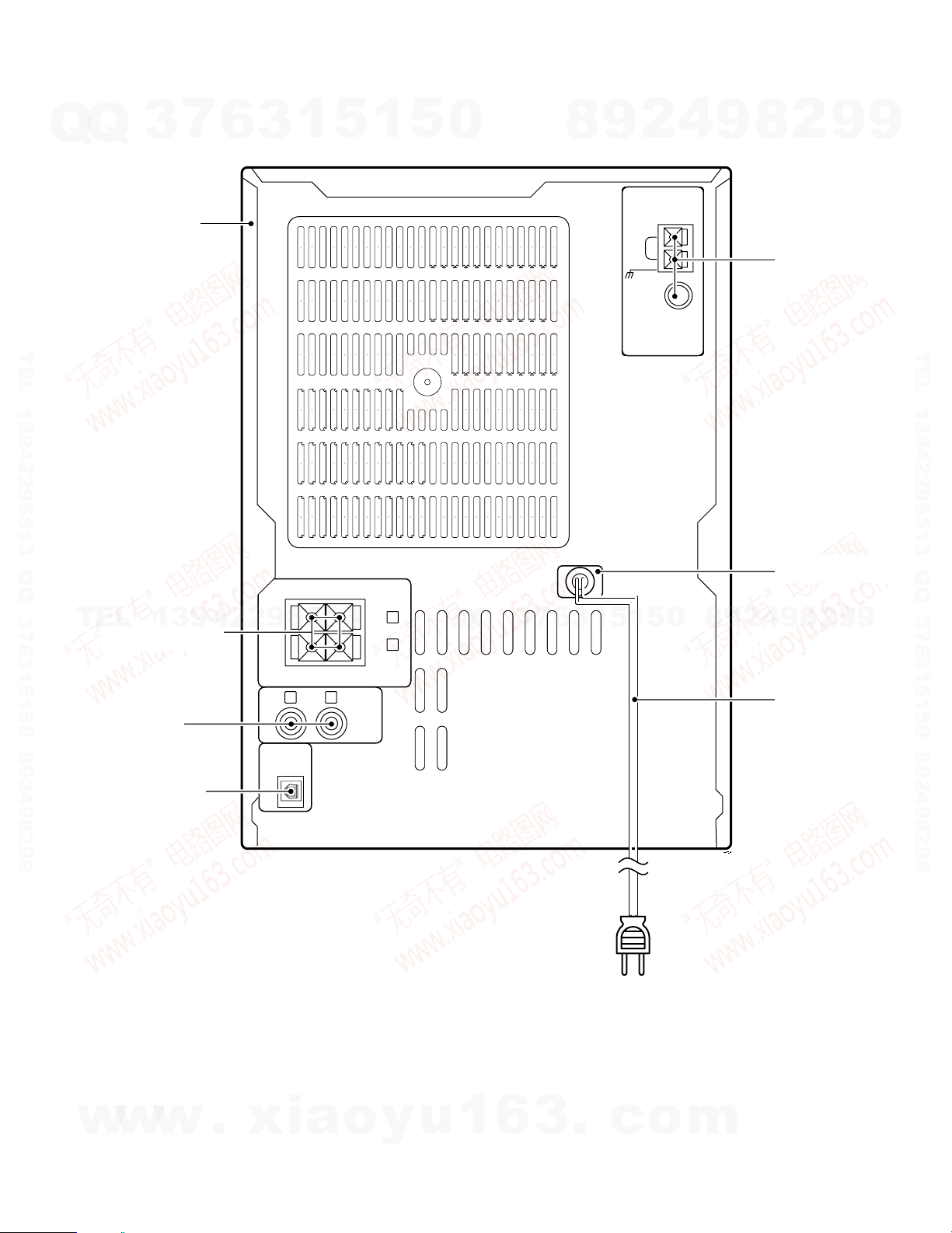
EXTERNAL VIEW
7
Q
Q
TEL 13942296513 QQ 376315150 892498299
3
Metallic cabinet *
(A01-)
6
3
1
5
1
5
0
8
9
2
4
9
2
8
Tuner ass'y *
(W02-)
AC power cord bushing
(J42-0349-05)
9
9
TEL 13942296513 QQ 376315150 892498299
TEL
Lock terminal board
(E70-0123-15)
Pin jack
(E63-1264-05)
Oscillating module
(W02-1114-15)
* Refer to parts list on page 21.
13942296513
Q
Q
3
7
6
3
1
5
1
5
0
8
9
9
4
2
AC power cord *
(E30-)
8
2
9
9
w
w
w
.
xia
o
y
u
1
6
3
.
c
o
m
3
RXD-M66/LS-M66
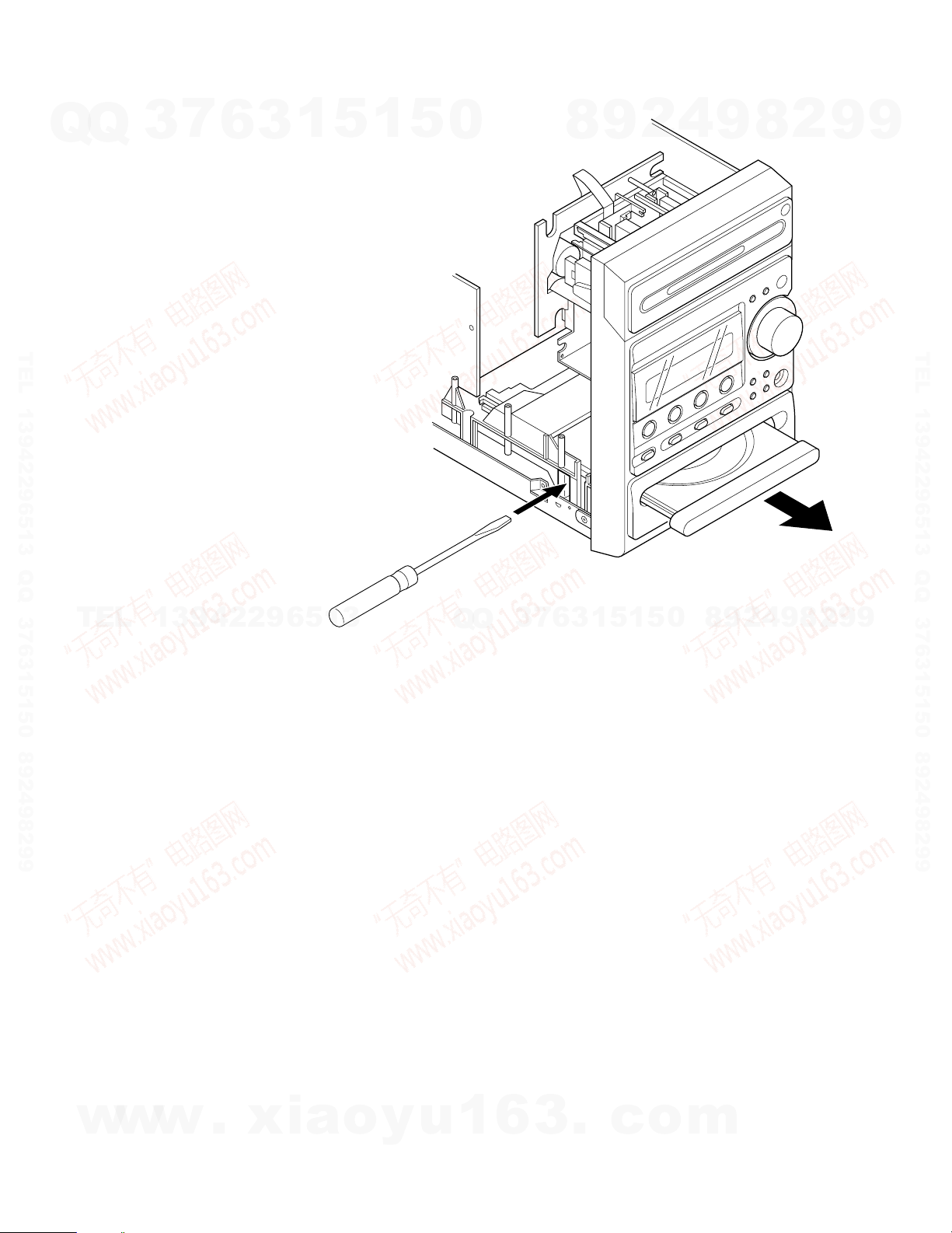
DISASSEMBLY FOR REPAIR
How to open the CD tray when it does not come out.
Q
Q
1. Insert a flat driver and so on to a square hole in the mechanism as
shown in the figure.
2. Push a rack gear in the direction of arrow.
(At this time, the tray comes out slightly frontward.)
3. The tray can be opened by hand.
TEL 13942296513 QQ 376315150 892498299
3
7
6
3
1
5
1
5
0
8
9
2
4
9
8
2
9
9
TEL 13942296513 QQ 376315150 892498299
TEL
13942296513
Q
Q
3
7
6
3
1
5
1
5
0
8
9
2
4
9
8
2
9
9
4
w
w
w
.
xia
o
y
u
1
6
3
.
c
o
m
RXD-M66/LS-M66
DIGITAL
OUT
OPTICAL
AUX
INPUT
L
R
FRONT
SPEAKERS
(6-16
Ω)
L
-
+
R
(TAPE Lch),3 pin
X28 CN1
(TAPE Rch),5 pin
{
(A)
(B)
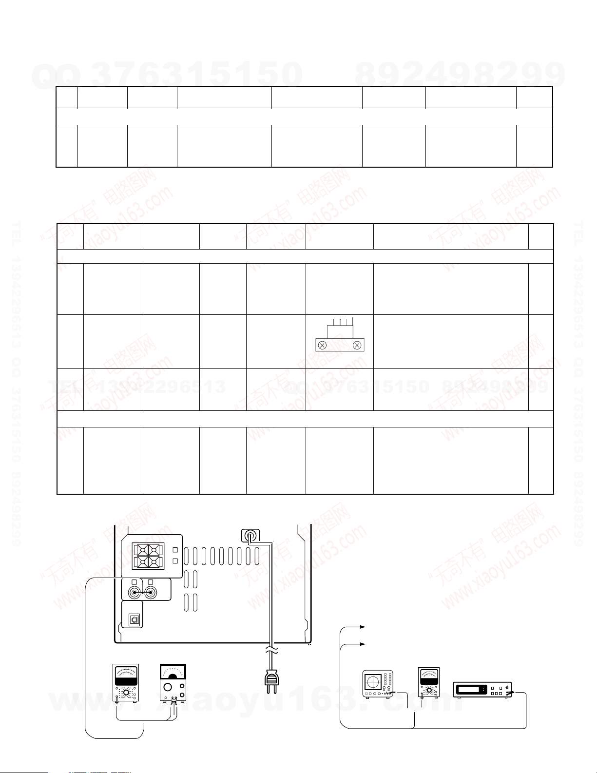
Fig.1
AC voltmeter AG
Oscilloscope AC voltmeter
Frequency counter
ADJUSTMENT
CD player adjustment
Q
Q
No.1ITEM
Insert the AC cord to AC wall outlet while holding down the [CD PLAY/PAUSE] key.
CURRENT
Note:
Type 4disc :SONY YEDS-18 Test Disc or equivalent. (KTD-02)
LPF : Around 47kΩ + 390pF or so.
TEL 13942296513 QQ 376315150 892498299
Cassette Deck adjustment
No
ø. CASSETTE MECHANISM UNIT
< 1 >
< 2 >
7
3
LASER
ITEM
Demagneti-
zation and
cleaning
Azimuth of
the
REC/PLAY
head
6
3
INPUT
SETTING
Test disc
Type 4
INPUT
SETTING
SCC-1727
TCC−153
MTT−114
10kHz,
− 10dB
1
5
OUTPUT
SETTING
Connect the DC
voltmeter to
CN23(#1 and #2) in
–
X29
OUTPUT
SETTING
–
(A)
1
5
SETTING
Demagneti-
POWER OFF
Cleaning:
0
PLAYER
SETTING
Press the "PLAY" key
to check that the dis-
play is "03" or "05"
DECK
zation:
PLAY
PLAY
ALIGNMENT
POINT
Recording
head, erase
head,capstan
pinch roller
RVS FWD
4
2
9
8
ALIGNMENT
POINT
–
Demagnetize the REC / PLAY head
with the head eraser. Clean the REC
/ PLAY head, erase head,capstan and
pinch roller using a cotton swab
slightly damped with alcohol.
Adjust the output to maximum and
adjust the azimuth adjustment screw
for the Lissajours waveform pattern of
the oscilloscope to become close to a
9
ALIGN FOR FIG.
220mV to 550mV
ALIGN FOR
45° straight line.
2
8
0dBs=0.775V
9
FIG.
9
TEL 13942296513 QQ 376315150 892498299
TEL
¿. PC BOARD ADJUSTMENT
< 1 >
SYSTEM CONNECTIONS
13942296513
(NORMAL)
BIAS
CURRENT
TAPE SPEED
< 3 >
TCC−110
MTT−111
SCC−1727
3kHz
(B)
Connect the
AG to jack.
1kHz:
-30dBs
10kHz:
-30dBs
(A)
(A)
PLAY
Q
REC and
PLAY
Trimming pot
3
Q
in the motor.
VR 1 (L)
VR 2 (R)
(X28)
7
6
Check the tape speed so that
3kHz(±2%) is obtained at the center
5
1
3
Record 1kHz and 10kHz alternately,
and adjust the bias current adjust-
ment potentiometer for the playback
levels (-21dBs)to become the same.
1
5
0
of the tape.
8
9
2
4
9
8
2
9
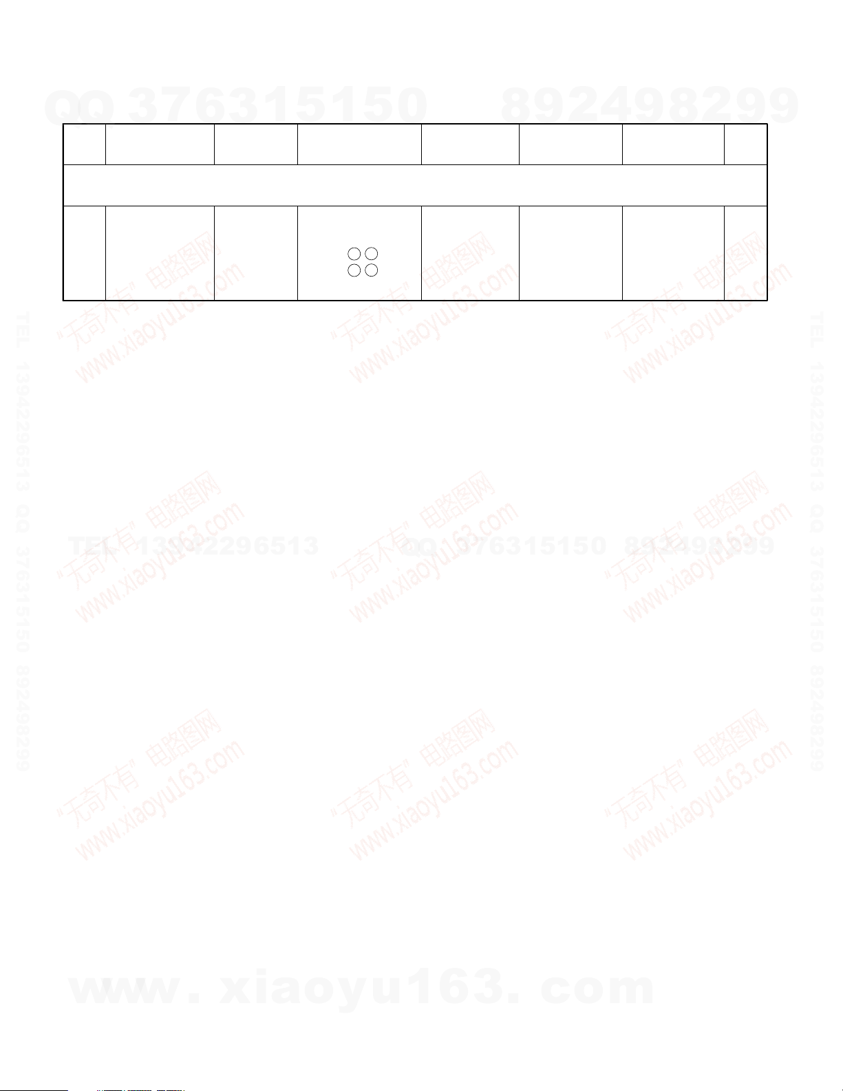
Fig.1
9
w
w
w
.
xia
o
y
u
1
6
3
.
c
o
m
5
RXD-M66/LS-M66
No. ITEM
INPUT
SETTINGS
OUTPUT
SETTINGS
AMPLIFIER
SETTINGS
ALIGNMENT
POINTS
ALIGN FOR FIG.
Unless otherwise specified, the individual switches should be set as following :
POWER : ON
1 IDLE CURRENT –
Connect a DC
voltmeter to
CN11 ( 1 2 ), Rch
CN11 ( 3 4 ), Lch
(X29)
VOLUME : 0
VR1 (L)
VR2 (R)
(X29)
4.4 mV
ADJUSTMENT
7
Q
Q
TEL 13942296513 QQ 376315150 892498299
3
6
3
1
5
1
5
0
8
9
2
4
9
8
2
9
9
TEL 13942296513 QQ 376315150 892498299
TEL
13942296513
Q
Q
3
6
7
3
1
0
5
1
5
8
9
2
4
9
8
2
9
9
w
w
w
6
.
xia
o
y
u
1
6
3
.
c
o
m
CD OPEN
R407
W508
W513
41
4443402718521
W514
W515
W516
W518
C408
C403
C406
R403
R402
R405
R406
C405
C404
C503
C504
C505
C506
R513
R521
R524
R501
R502
R503
R505
R506
R507
R508
R509
R510
R522
R523
R534
1
1
3
5
4
4
C507
SECONDARY
PRIMARY
YEL
240V120V
MAIN TRANSFORMER
F2
F1
T1.25A L 250V
T1.25A L 250V
WHT
21
AUX
TAPE PLAY
O.T.E
4MHz
SOUND
REPEAT
WHT
1
2
SKIP UP
SKIP DOWN
STANDBY/ON
STOP/
MODE
TUNIN
MODE
TUNER
CD
PLAY/PAUSE
2
117
16
WHT
SET/
DEMO
REC
W407
W405
C402
K401
14 1
R404
T401
R401
W403
W406
W404
W501
W511
W502
W504
W505
W506
W503
W507
13
46
1
11
12
22
23
33
34
44
EBC
EBC
R504
X501
E
B
G
IO
E
12
B
C511
R515
R514
R512
R511
C501
C502
R516
R517
R518
VOLUME
R520
R533
R535
R548
R547
R546
R545
R544
R543
R542
R541
R540
R539
R538
R537
R536
IC402
IC501
Q501
D408
Q401
Q402
D401
D402
D404
D405
D406 D407
D409
D503
S501
S502
S503
S504 S505
S506
S507
S508
S509
S510
S512
S513
S514
S515
WH401
S401
E502
ED501
P401
D403
CN402
CN403
CN404
IC401
E401
CN405
CN406
E503
CN502
A501
CN501
S516
WH501
S511
D501
CN503
WH502
X14 B/4
X14 D/4
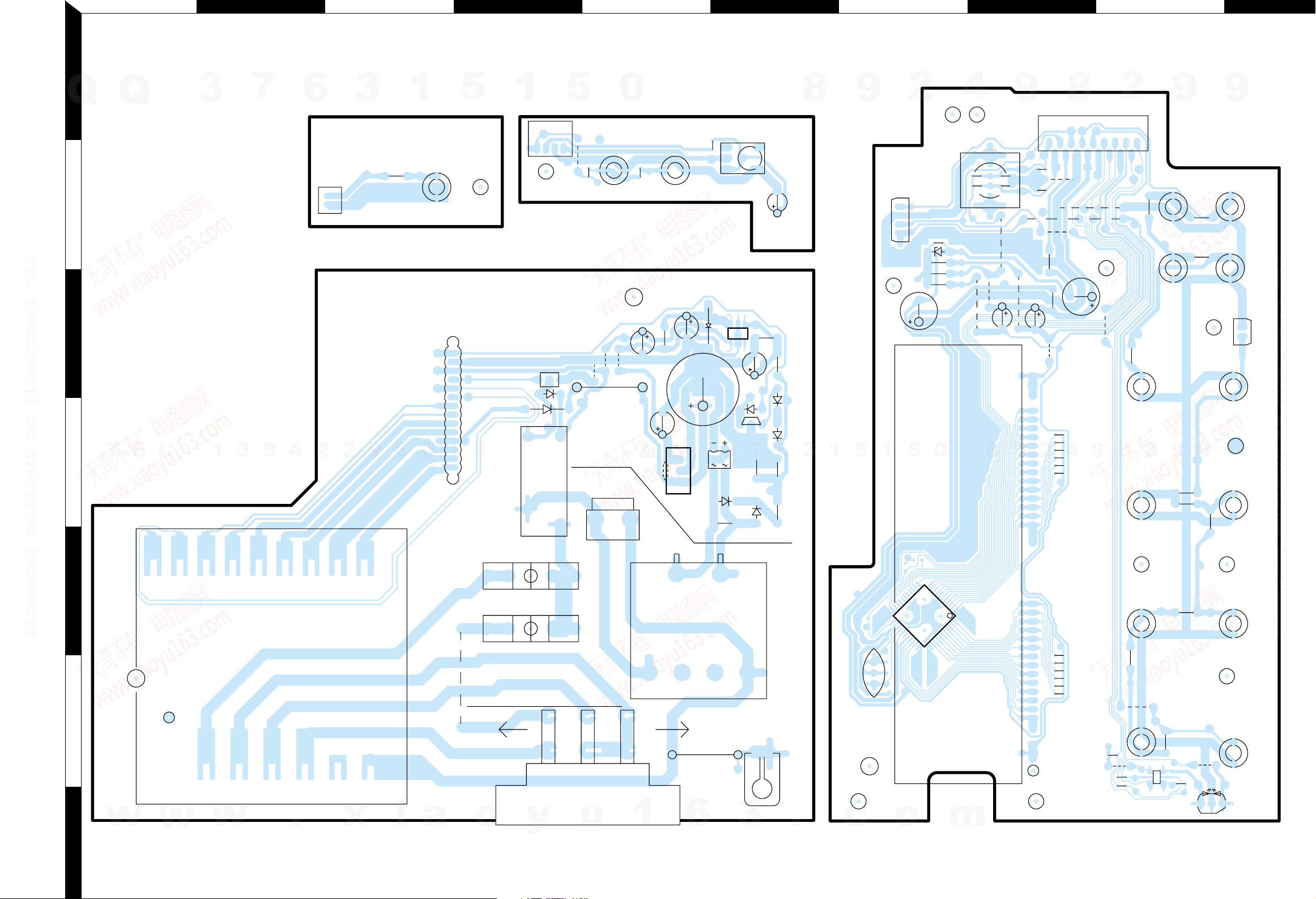
X14-7492-70 A/4 (J70-1594-11)
X14 C/4
ACEG IBDFHJ
PC BOARD (Component side view)
1
3
7
9
4
6
2
2
3
9
6
Q
2
Q
3
TEL 13942296513 QQ 376315150 892498299
3
T
E
4
5
L
1
1
5
1
5
3
1
5
0
Q
Q
3
7
6
8
3
1
9
5
1
2
5
4
0
8
9
9
2
9
2
8
8
4
2
9
9
9
TEL 13942296513 QQ 376315150 892498299
9
6
w
7
Refer to the schematic diagram for the value of resistors and capacitors.
w
w
.
x
i
a
o
y
u
1
8
6
7
3
.
c
o
m
 Loading...