

Page 1

B60-4326-00 01 CH (T) MC
i
Page 2
Connecting and Setting Up Your New Kenwood Audio-Video Receiver
Welcome to the Connection and Setup Guide for
your new Kenwood Audio-Video Receiver.
The KRF-X9992D offers two kinds of 5.1-channel
digital decoding:
• Dolby® Digital, for the hundreds of currently
available Dolby Digital DVDs and LaserDiscs.
• MPEG, a well-established multichannel format
in movie theaters, is available for home theater
on LaserDisc and DVD.
Use it to connect all your current audio and video
components—the KRF-X9992D has a variety of
connection jacks so you can customize your entertainment setup.
KRF-X9992D also provides THX Ultra feature to
bring the movie theatre environment into the home.
It also includes Kenwood’s remarkable PowerTouch
LCD remote—a graphical user interface without
having to use your TV!
Other advanced features include 5 S-Video inputs
and an optical digital output for digital dubbing to
MiniDisc.
©Lucasfilm Ltd. & TM. All rights reserved. Used under
authorization.
Lucasfilm, THX are registered trademarks of
Lucasfilm Ltd.
ii
Manufactured under license from Dolby Laboratories. “Dolby”, “Pro Logic”, and the double-D symbol
“DTS” and “DTS Digital Surround” are trademarks
of Digital Theater Systems, Inc.
are trademarks of Dolby Laboratories. Confidential
Unpublished Works. © 1992-1997 Dolby Laboratories. All rights reserved.
Unpacking
Unpack your new receiver carefully and make sure that all the accessories are present:
PowerTouch Remote
t
i
d
e
e
i
ENTER
v
o
m
c
i
s
u
m
UP
d
n
u
E
o
CONFIRM
M
U
s
L
O
V
o
m
d
n
e
t
s
i
l
o
r
c
a
DOWN
m
ON/STANDBYCONTRAST REMOTE OFF
Batteries
If any accessories are missing, or if the receiver is damaged or fails to operate, notify your dealer immediately. If your receiver was shipped to you directly, notify your
shipper immediately. Kenwood recommends that you retain the original carton and packing materials in case you need to move or ship the receiver in the future.
AM Loop Antenna FM AntennaAM Antenna Base
Page 3
KRF-X9992D is designed for operation as follows.
U.K. and Europe........................... AC 230 V only
Before Applying Power
Read this section carefully to ensure safe operation.
Factory fitted moulded mains plug
1. The mains plug contains a fuse. For replacement, use only a 13-Amp ASTA-approved (BS1362) fuse.
2. The fuse cover must be refitted when replacing the fuse in the moulded plug.
3. Do not cut off the mains plug from this equipment. If the plug fitted is not suitable for the power
points in your home or the cable is too short to reach a power point, then obtain an appropriate
safety approved extension lead or adapter, or consult your dealer.
If nonetheless the mains plug is cut off, remove the fuse and dispose of the plug immediately, to
avoid a possible shock hazard by inadvertent connection to the mains supply.
IMPORTANT : The wires in the mains lead are coloured in accordance with the following code:
Blue : Neutral
Brown : Live
Do not connect those leads to the earth terminal of a three-pin plug.
Safety Precautions
Read this section carefully to ensure safe operation.
iii
WARNING :
TO PREVENT FIRE OR ELECTRIC
SHOCK, DO NOT EXPOSE THIS APPLIANCE TO RAIN OR MOISTURE.
CAUTION: TO REDUCE THE RISK OF ELECTRIC SHOCK, DO
CAUTION
RISK OF ELECTRIC SHOCK
DO NOT OPEN
THE LIGHTNING FLASH WITH ARROWHEAD SYMBOL, WITHIN AN EQUILATERAL TRIANGLE,
IS INTENDED TO ALERT THE USER TO THE PRESENCE OF UNINSULATED “DANGEROUS
VOLTAGE” WITHIN THE PRODUCT’S ENCLOSURE THAT MAY BE OF SUFFICIENT MAGNITUDE TO CONSTITUTE A RISK OF ELECTRIC SHOCK TO PERSONS.
THE EXCLAMATION POINT WITHIN AN EQUILATERAL TRIANGLE IS INTENDED TO ALERT
THE USER TO THE PRESENCE OF IMPORTANT OPERATING AND MAINTENANCE (SERVICING) INSTRUCTIONS IN THE LITERATURE ACCOMPANYING THE APPLIANCE.
NOT REMOVE COVER (OR BACK). NO USER-SERVICEABLE
PARTS INSIDE. REFER SERVICING TO QUALIFIED SERVICE
PERSONNEL.
Page 4

Chapter One: Connecting Your
Devices .................................................. 1
Noting Your Devices .............................................. 3
Connecting Your Speakers ..................................... 4
To Connect Front Speakers Only:
To Connect Front and Surround Sound
Speakers:
What if I Have a Powered Subwoofer?
What if I Have an Amplifier?
Connecting Your TV............................................... 8
iv
To Connect a TV:
What if I Want to Watch TV without Turning
on the Receiver?
Connecting Your Cable TV or Satellite Tuner ..... 10
To Connect a Cable TV Tuner with a
Composite (RCA) Video Output:
To Connect a Cable TV Tuner without a
Composite (RCA) Video Output:
To Connect a Satellite Tuner:
Connecting Your VCR(s) ..................................... 12
To Connect a Primary VCR:
To Connect a Secondary VCR:
Connecting Your Primary CD Player ................... 14
What if I Have a Video CD-Compatible CD
Player?
Table of Contents
To Connect a Kenwood 200-Disc CD
Changer:
To Connect Any Other Primary CD Player or
Changer:
To Connect a Secondary CD Player:
Connecting Your DVD Player ..............................16
To Connect a DVD Player:
Connecting Your DVD Player Through a Surround
Processor .......................................................... 18
To Connect a DVD Player Through a
Surround Processor:
Connecting Your MD Recorder or Primary
Tape Deck ......................................................... 20
To Connect an MD Recorder:
To Connect a Primary Tape Deck:
To Connect a Secondary Tape Deck:
Connecting Your Secondary CD Player or
Tape Deck ......................................................... 22
To Connect a Secondary CD Player:
To Connect a Secondary Tape Deck:
Connecting Your Laser Disc Player
(with AC-3 RF Output) .....................................24
To Connect an AC-3 RF Output Laser Disc
Player:
Audio-Video Receiver KRF-X9992D
Connecting Your Laser Disc Player
(without AC-3 RF Output)................................ 26
To Connect a PCM Digital Output Laser Disc
Player:
Connecting Your Turntable/Record Player .......... 28
To Connect a Turntable/Record Player:
Connecting a Camcorder or Additional VCR ...... 29
To Connect a Camcorder or Additional VCR:
Can I Connect an Additional VCR Perma-
nently?
What if I Have Several Kenwood Devices (System
Control Chaining)? .......................................... 30
An Example of SL16 Chained
Connections:
An Example of XS8 Chained
Connections:
Connecting the Antennas .................................... 31
AM Loop Antenna
FM Indoor Antenna
FM Outdoor Antenna
What if I Have Cable Radio?
Page 5

Table of Contents
Chapter Two: Setting Up PowerTouch... 32
Installing the Batteries.........................................32
Calibrating the Touch Screen .............................. 33
Resetting PowerTouch
Navigating PowerTouch Interface ........................ 34
Setting Up Speakers ............................................. 34
SP Selection
SP Distance
SP Level
Bass Peak Level
Audio-Video Receiver KRF-X9992D
Identifying Devices For PowerTouch Control ..... 37
How Do I Identify Devices?
How Do I Replace a Setup Code with a New
One?
How Do I Delete Setup Codes?
What if my device does not work with any of
the codes on the list?
What if I Want PowerTouch to Control
Additional Functions?
Storing Radio Stations in Memory (optional) ....40
Storing RDS Stations Automatically
Storing Stations Manually
Chapter Three: Specifications ................ 42
KRF-X9992D Specifications
v
Page 6

vi
Audio-Video Receiver KRF-X9992D
Page 7

Chapter One : Connecting Your Devices Audio-Video Receiver KRF-X9992D
Chapter One: Connecting Your Devices
Connections
Welcome to the Kenwood KRF-X9992D Connection
and Setup Guide. This chapter guides you through
connecting your home entertainment devices to
your new Kenwood audio-video receiver.
Once all your devices are connected, you can set up
the PowerTouch (see Chapter Two).
Refer to the following pages for details on connecting these devices:
Speakers page␣ 4
TV page␣ 8
VCR(s) page␣ 12
CD Player, Kenwood 200-Disc Changer page␣ 14
DVD Player page␣ 16
MD Recorder page␣ 20
Tape Deck(s) page␣ 20
Laser Disc Player page␣ 24
Turntable page␣ 28
Camcorder/Second VCR page␣ 29
Antennas page␣ 31
All necessary cables should be provided with your
home entertainment device (not with your new
receiver). If you do not have the correct cables, you
may purchase these cables from any home entertainment store.
To make coaxial digital connections, be sure to use a
high-quality digital audio cable, not a standard
audio cable.
Do not plug in the receiver or any other device to
AC power until all connections have been made.
Once all devices have been connected, you may plug
them in and provide power.
Important:
Your new receiver requires adequate ventilation to
perform reliably. Be sure not to block the ventilation
area on the top or back (or both sides) of the
receiver with another device. These areas should be:
at least top; 50cm, back; 10cm, and left and right
side; 10cm
Do not install your receiver where direct sunlight or
high frequency flourescent lighting can shine
directly into the remote sensor. This can cause your
new receiver to malfunction.
Before You Begin
This manual covers the most common and standard
connections to the receiver. Because of its versatility,
you may decide to connect your devices differently.
Before making any video connections to the your
receiver :
• You can use either S-Video or standard composite (RCA) video connections.
• If all of your video devices and TV have S-Video
connectors, we suggest that you use them
exclusively, since it will provide superior video
performance.
• If only some of your video devices and TV have
S-Video connectors, you can still use them for
those devices and the TV. Use the composite
connectors for your devices that don’t have SVideo connectors. In this case you’ll also have to
connect the receiver’s composite Video Monitor
output to your TV for your non S-Video devices
and switch between inputs on TV.
• If your TV doesn’t have S-Video connectors, you
can’t use S-Video connections for any of your
video devices. Use the composite connectors
exclusively.
• If your TV does not have any video connections
at all (it only has antenna connections), you
must purchase an RF modulator that converts
video signals into antenna signals to use it with
the KRF-X9992D. You should be able to find an
RF modulator at a store specializing in electronic
parts.
1
Page 8
Chapter One : Connecting Your Devices Audio-Video Receiver KRF-X9992D
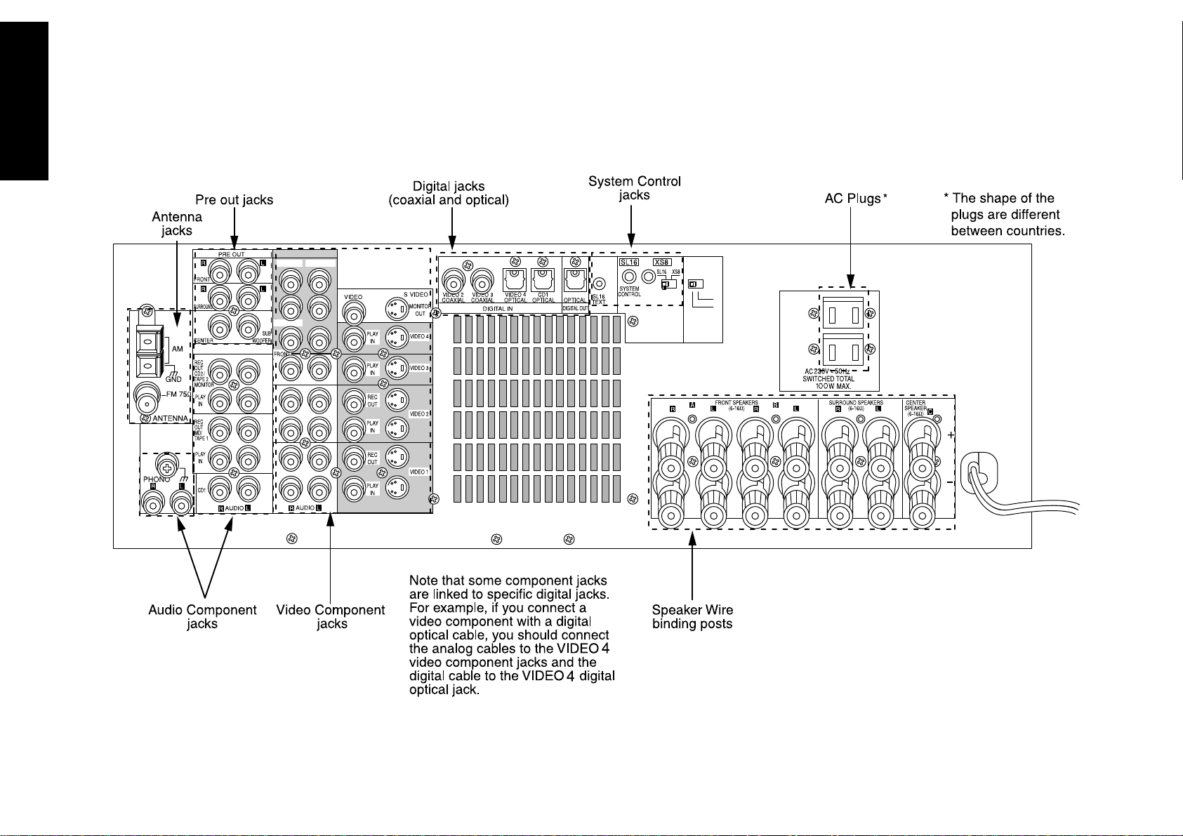
Connections
The following diagram shows the entire back of the KRF-X9992D.
VIDEO4 6CH.INPUT
CENTER
SUBWOOFER
SURROUND
VIDEO 4
INPUT
6 CH
2 CH
2
Page 9

Chapter One : Connecting Your Devices Audio-Video Receiver KRF-X9992D
Noting Your Devices
Jack Set Device Manufacturer Model # Setup Code
Phono
CD1
MD/Tape1
CD2/Tape2 Monitor
Video
(TV1 on PowerTouch)
Connections
Video1
Video2
Video3
Video4
Use this table and the diagram on the preceding
page to plan your connections before you make
them, or use it to record your connections as you
make them. If you will be connecting a DVD player
or other device with a digital output, please refer to
the following chart before choosing a video jack set:
If your digital
cable is...
optical VIDEO4
coaxial VIDEO2 or 3
Choose this jack
set...
3
You will need this information later, when you set
up your PowerTouch (see “Identifying Devices For
PowerTouch Control” on page␣ 37). Recording this
information now will save you additional trips
behind your home entertainment cabinet. You will
fill in the Setup Code column when you are setting
up PowerTouch.
Page 10
Chapter One : Connecting Your Devices Audio-Video Receiver KRF-X9992D
Connections
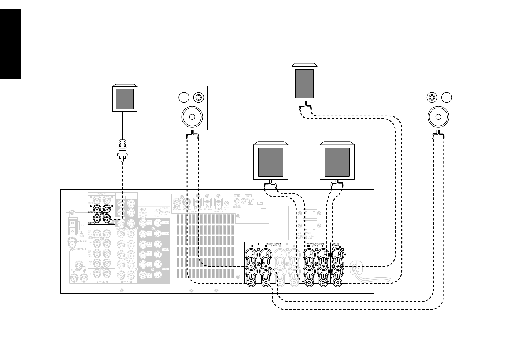
Connecting Your Speakers
CENTER
L
FRONT
POWERED
R
FRONT
SUBWOOFER
R
SURROUND
L
SURROUND
4
VIDEO4 6CH.INPUT
CENTER
SUBWOOFER
SURROUND
VIDEO 4
INPUT
6 CH
2 CH
A B
C
Page 11
Chapter One : Connecting Your Devices Audio-Video Receiver KRF-X9992D
Connecting Your Speakers, continued
Connections
Do not plug in the receiver to AC power until all
connections have been made.
To Connect Front Speakers Only:
If you only intend to listen to stereo sound (as
opposed to surround sound), you may simply
connect a single pair of speakers. To do so:
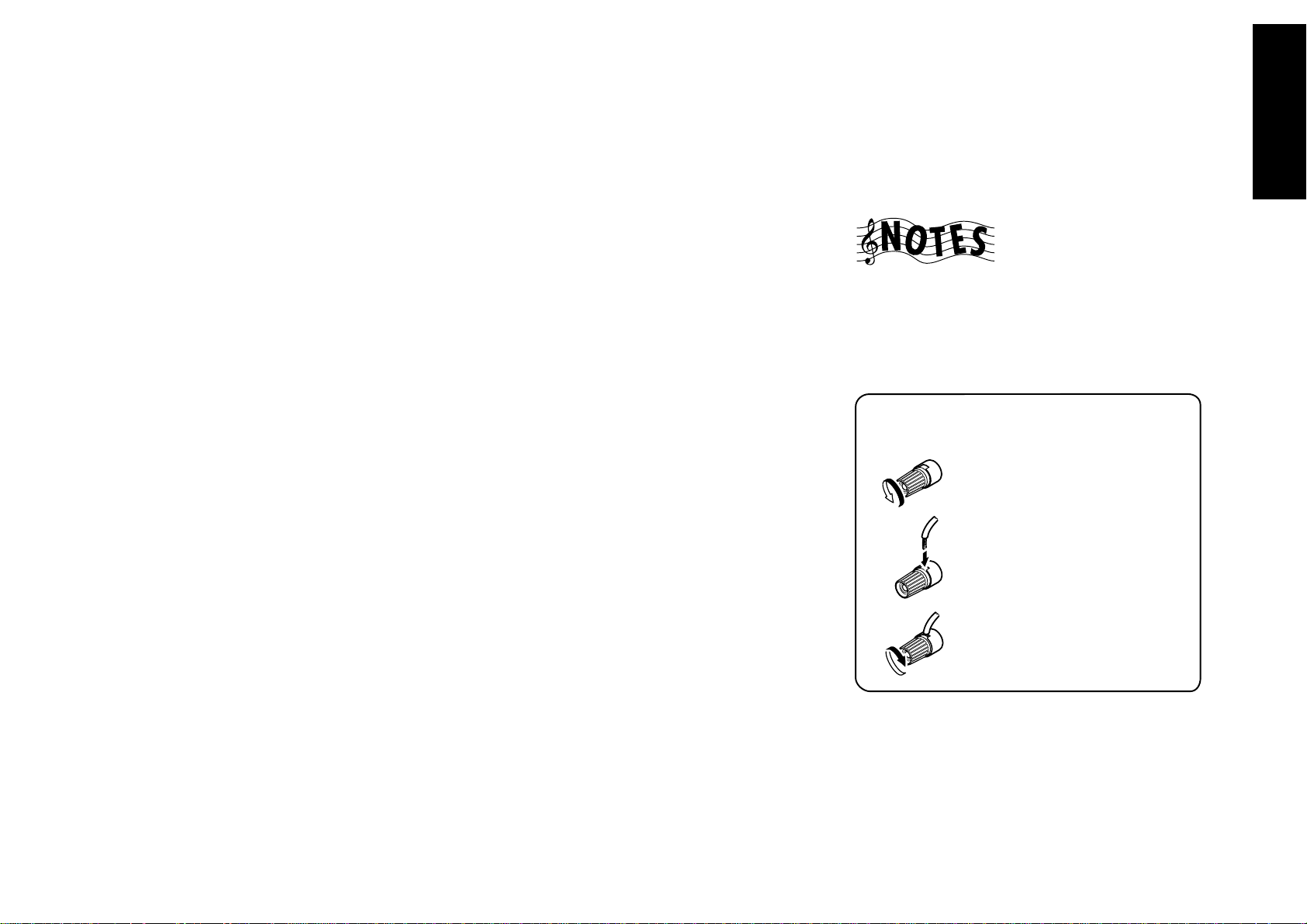
1. Loosen the speaker wire binding posts.
2. Insert the wire from the positive jack on the
RIGHT FRONT speaker into the U-shaped slot in
the base of the positive RIGHT FRONT post. Lay
the wire to the right of the post; that way, when
you tighten the binding post, it will naturally
twist the wire into the best connection. Tighten
the post. Repeat for the negative wire on the
RIGHT FRONT speaker as shown to the right.
3. Repeat step 2 for the positive and negative wires
on the LEFT FRONT speaker.
To Connect Front and Surround Sound
Speakers:
To listen to the full surround sound that this
receiver can put out, connect front speakers, center,
left surround, and right surround speakers. To do so:
1. Loosen the speaker wire binding posts.
2. Follow the steps under “To Connect Front
Speakers Only” on this page to connect the
RIGHT and LEFT FRONT speakers.
3. Insert the wire from the positive jack on the
CENTER speaker into the U-shaped slot in the base
of the positive CENTER post, as shown to the right.
Tighten the post. Repeat for the negative wire.
4. Insert the wire from the positive jack on the
RIGHT SURROUND speaker into the U-shaped
slot on the base of the positive RIGHT SURROUND post. Tighten the post. Repeat for the
negative wire.
5. Repeat step 4 for the positive and negative wires
on the LEFT SURROUND speaker.
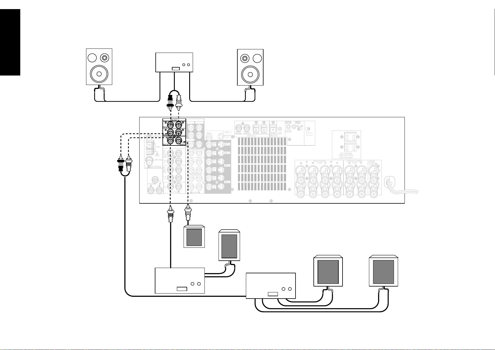
What if I Have a Powered Subwoofer?
Simply connect the subwoofer’s audio cable to the
receiver’s subwoofer PRE OUT jack as shown to the
left.
Never short circuit the + and - speaker wires.
Do not switch the left and right speaker wires or
swap the + and - wires on the binding posts.
The speakers must have a nominal impedance of
between 6Ω and 16Ω.
Using Speaker Wire
5
1. Loosen post
2. Insert wire
3. Tighten post
Page 12
Chapter One : Connecting Your Devices Audio-Video Receiver KRF-X9992D
What if I Have an Amplifier?
Connections
6
FRONT
FRONT
L
VIDEO 4
INPUT
6 CH
2 CH
R
Power Amp
VIDEO4 6CH.INPUT
CENTER
SUBWOOFER
SURROUND
POWERED
SUBWOOFER
Power Amp
CENTER
Power Amp
R
SURROUND
L
SURROUND
Page 13

Chapter One : Connecting Your Devices Audio-Video Receiver KRF-X9992D
What if I Have an Amplifier?, continued
You can use supplemental power amplifiers for any
of the channels instead of the receiver’s built-in
amplifiers.
Do not plug in the amplifiers or the receiver to AC
power until all connections have been made.
To connect supplemental power amplifiers:
1. Using RCA audio cables (not supplied), connect
the receiver’s PRE OUT jacks to the amplifiers’
input jacks as shown to the left.
2. Connect the speakers to the power amplifiers
according to the amplifiers’ instruction manuals.
Connections
7
Page 14
Chapter One : Connecting Your Devices Audio-Video Receiver KRF-X9992D
Connections
Connecting Your TV
VIDEO4 6CH.INPUT
CENTER
SUBWOOFER
8
SURROUND
COMPOSITE VIDEO
S-VIDEO
Page 15

Chapter One : Connecting Your Devices Audio-Video Receiver KRF-X9992D
Connecting Your TV, continued
Connections
Do not plug in the receiver or devices to AC power
until you have connected all your devices.
This section focuses on the connections from your
TV to the KRF-X9992D. Please refer to your TV’s
instructions for more detail about its connection
jacks and capabilities.
The instructions in this section show how to connect your TV as a monitor for the other video
devices you connect (without using it as an audio/
video source device itself). To use your TV as an
audio/video source device, you must first connect it
as described in this section, and also connect its
audio/video output jacks as if they were cable TV
tuner outputs, as described in “To Connect a Cable
TV Tuner with a Composite (RCA) Video Output”
on page 11.
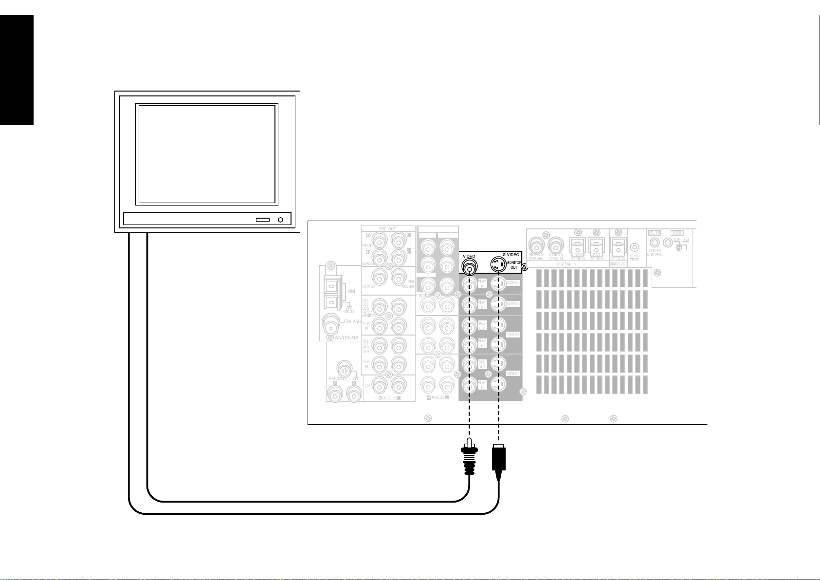
To Connect a TV:
1. Review the information under “Before You
Begin” on page␣ 1. It contains important notes
about the types of video connections you can
make.
2. Connect a video cable from your TV’s Video IN
jack to the receiver’s MONITOR OUT jack as
shown to the left.
3. If your TV does not have any video input connections, you must purchase an RF modulator. The
modulator will convert the video signal from the
receiver to an RF signal that will work with the
TV’s antenna connections.
Connect the receiver to the TV according to the
RF modulator’s instruction manual.
4. Go to “Noting Your Devices” on page␣ 3 and note
which jack you used to connect your TV. In
addition, note the brand name and model
number of the TV.
If you previously connected your TV directly to your
VCR, you must now connect it through your new
receiver.
What if I Want to Watch TV without
Turning on the Receiver?
The connection described here sets your TV up as a
monitor you can use to view media played on your
other video devices (such as a VCR or DVD player).
You can still watch TV without having to use the
receiver.
9
Page 16
Chapter One : Connecting Your Devices Audio-Video Receiver KRF-X9992D
Connecting Your Cable TV or Satellite Tuner
Connections
10
Note that video device jacks are linked to specific digital jacks. For example, if you connect a
satellite tuner with a digital coaxial cable, you should connect the analog cables to the VIDEO
2 video device jacks and the digital cable to the VIDEO2 digital COAXIAL jack.
Page 17

Chapter One : Connecting Your Devices Audio-Video Receiver KRF-X9992D
Connecting Your Cable TV or Satellite Tuner, continued
Connections
Do not plug in the receiver or devices to AC power
until you have connected all your devices.
This section focuses on the connections from your
cable or satellite tuner to the KRF-X9992D. Please
refer to your tuner’s instructions for more detail
about its connection jacks and capabilities.
The instructions in this section show one of several
possible variations on connecting your tuner. For
further assistance on optional configurations,
contact your cable or satellite provider.
To Connect a Cable TV Tuner with a
Composite (RCA) Video Output:
1. Review the information under “Before You
Begin” on page␣ 1. It contains important notes
about the types of video connections you can
make.
2. Connect the audio and video cables from the
cable tuner’s Audio and Video Out jacks to the
receiver’s VIDEO 2, VIDEO 3, or VIDEO 4 PLAY
IN jacks as shown to the left.
3. Go to “Noting Your Devices” on page␣ 3 and note
which jack you used to connect your tuner. In
addition, note the brand name and model
number of the tuner.
To Connect a Cable TV Tuner without a
Composite (RCA) Video Output:
1. Review the information under “Before You
Begin” on page␣ 1. It contains important notes
about the types of video connections you can
make.
2. Connect the audio cables from the cable tuner’s
Audio Out jacks to the receiver’s VIDEO 2,
VIDEO 3, or VIDEO 4 PLAY IN jacks as shown to
the left.
3. Leave the cable tuner’s video out (RF jack)
connected directly to your VCR or TV (wherever
you already have it connected). See “How Do I
Operate Devices?” on page␣ 26 of the Users’ Guide
for details about using this setup.
To Connect a Satellite Tuner:
1. Review the information under “Before You
Begin” on page␣ 1. It contains important notes
about the types of video connections you can
make.
2. If your satellite receiver has a digital output, use
the table below to select a jack set:
If your digital
cable is...
optical VIDEO4
coaxial VIDEO2 or 3
Note that the jack sets are linked, even though
they are not adjacent. You must connect all of
the cables from your satellite receiver to a linked
jack set. For example, if you connect the analog
cables to VIDEO2 and the digital optical cable to
VIDEO4,␣ your satellite receiver will not work
correctly.
3. Connect the audio and video cables from the
satellite tuner’s Audio and Video Out jacks to the
receiver’s VIDEO 2, VIDEO 3, or VIDEO 4 PLAY
IN jacks as shown to the left.
4. Go to “Noting Your Devices” on page␣ 3 and note
which jack you used to connect your tuner. In
addition, note the brand name and model
number of the tuner.
Choose this jack
set...
11
4. Go to “Noting Your Devices” on page␣ 3 and note
which jack you used to connect your tuner. In
addition, note the brand name and model
number of the tuner.
Page 18
Chapter One : Connecting Your Devices Audio-Video Receiver KRF-X9992D
Connections
12
Connecting Your VCR(s)
VIDEO4 6CH.INPUT
CENTER
SUBWOOFER
SURROUND
AUDIO IN
AUDIO OUT
VIDEO OUT
VIDEO IN
S-VIDEO OUT
S-VIDEO IN
Page 19

Chapter One : Connecting Your Devices Audio-Video Receiver KRF-X9992D
Connecting Your VCR(s), continued
Connections
Do not plug in the receiver to AC power until you
have connected all your devices.
This section focuses on the connections from your
VCR to the KRF-X9992D. Please refer to your VCR’s
instructions for more detail about its connection
jacks and capabilities.
The instructions in this section show one of several
possible variations on connecting your VCR. For
further assistance on optional configurations,
contact the store where you purchased your receiver.
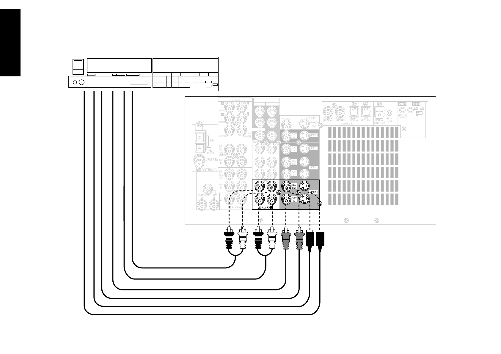
To Connect a Primary VCR:
1. Review the information under “Before You
Begin” on page␣ 1. It contains important notes
about the types of video connections you can
make.
2. Connect the audio and video cables from the
VCR’s Audio and Video jacks to the receiver’s
VIDEO 1 REC OUT and PLAY IN jacks as shown
to the left.
3. Be sure to connect the VCR Video IN cable to the
jack labeled REC OUT and the VIDEO OUT
cable to the jack labeled PLAY IN.
4. Go to “Noting Your Devices” on page␣ 3 and note
which jack you used to connect your VCR. In
addition, note the brand name and model
number of the VCR.
To Connect a Secondary VCR:
1. Review the information under “Before You
Begin” on page␣ 1. It contains important notes
about the types of video connections you can
make.
2. Connect the audio and video cables from the
VCR’s Audio and Video jacks to the receiver’s
VIDEO 2 REC OUT and PLAY IN jacks.
3. Be sure to connect the VCR Video IN cable to the
jack labeled REC OUT and the VIDEO OUT
cable to the jack labeled PLAY IN.
4. Go to “Noting Your Devices” on page␣ 3 and note
which jack you used to connect your VCR. In
addition, note the brand name and model
number of the VCR.
13
Page 20
Chapter One : Connecting Your Devices Audio-Video Receiver KRF-X9992D
Connections
14
Connecting Your Primary CD Player
VIDEO4 6CH.INPUT
CENTER
SUBWOOFER
SURROUND
OUTPUT A (CD1)
OUTPUT B (CD2)*
*KENWOOD
DPF-J9010 ONLY
DIGITAL OUTPUT
COMMUNICATION CABLE - KENWOOD ONLY
SYSTEM CONTROL CABLE - KENWOOD ONLY
Page 21

Chapter One : Connecting Your Devices Audio-Video Receiver KRF-X9992D
Connecting Your Primary CD Player, continued
Connections
Do not plug in the receiver to AC power until you
have connected all your devices.
This section focuses on the connections from your
200-Disc CD Changer to the KRF-X9992D. Please
refer to your changer’s instructions for more detail
about its connection jacks and capabilities.
Each set of instructions in this section shows one of
several possible variations on connecting your CD
player(s). For further assistance on optional configurations, contact the store where you purchased your
CD player(s).
The illustration shows a Kenwood 200-Disc CD
Changer. Your CD player may look different.
Kenwood DPF-J9010 contains two CD transports.
You must connect it as though they were two CD
players.
What if I Have a Video CD-Compatible
CD Player?
Connect the audio and video cables from the CD
player to any unused Video jack set.
Do not connect the system control cable in this
instance.
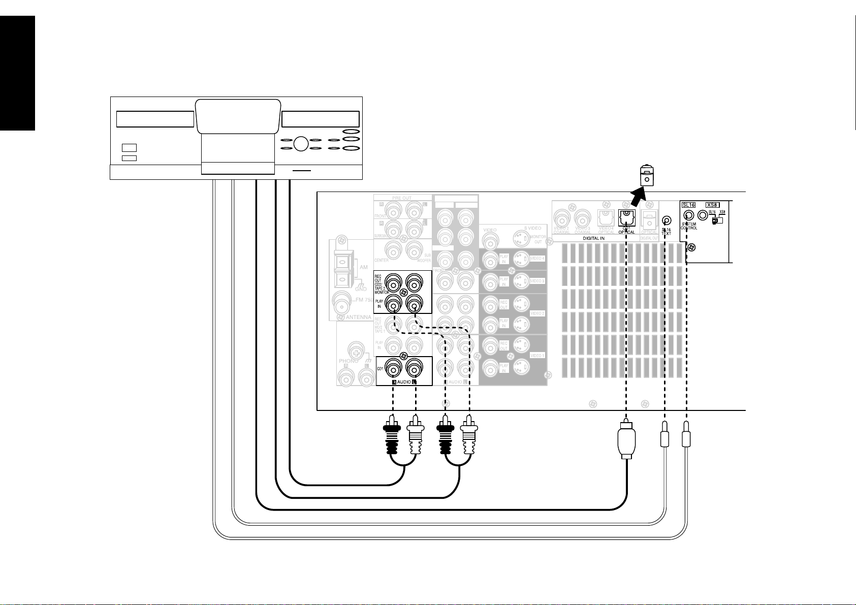
To Connect a Kenwood 200-Disc CD
Changer:
1. Connect the audio cables from the 200-Disc
Changer to the receiver’s CD1 jacks.
If you have a Kenwood DPF-J9010, connect
Output A to the receiver’s CD1 jacks and Output
B to the receiver’s CD2/Tape2 Monitor PLAY IN
jacks as shown to the left.
2. Connect the optical digital cable from the
changer to the receiver’s CD1 OPTICAL jack as
shown to the left.
3. Connect the system control cable from the
changer to the SYSTEM CONTROL jack as shown
to the left.
Be sure that the SL16/XS8 switch on both the
changer and the receiver is set to SL16.
If you are connecting more than one Kenwood
device with a system control cable, see “What if I
Have Several Kenwood Devices (System Control
Chaining)?” on page␣ 30 for more information.
4. Connect the SL16 text cable (communication
cable) from the changer to the receiver’s SL16
TEXT jack as shown to the left.
5. Go to “Noting Your Devices” on page␣ 3 and note
which jacks you used to connect your CD
changer. In addition, note the brand name and
model number of the CD Changer.
To Connect Any Other Primary CD
Player or Changer:
1. Connect the audio cables from the CD player’s
audio jacks to the receiver’s CD1 jack set as
shown to the left.
2. Connect the optical digital cable from the CD
player’s digital jack to the receiver’s CD1 OPTICAL jack as shown to the left.
3. If you are connecting a Kenwood CD Player with
system control, connect the system control cable
from the CD player to the system control jack as
shown to the left.
Be sure that the SL16/XS8 switch on both the
player/changer and the receiver is set appropriately.
If you are connecting more than one Kenwood
device with a system control cable, see “What if I
Have Several Kenwood Devices (System Control
Chaining)?” on page␣ 30 for more information.
4. Go to “Noting Your Devices” on page␣ 3 and note
which jacks you used to connect your CD player/
changer. In addition, note the brand name and
model number of the CD player or changer.
To Connect a Secondary CD Player:
See “Connecting Your Secondary CD Player or Tape
Deck” on page␣ 22.
15
Page 22
Chapter One : Connecting Your Devices Audio-Video Receiver KRF-X9992D
Connecting Your DVD Player
Connections
16
Note that video device jacks are linked to specific digital jacks. For example, if you connect a
DVD player with a digital optical cable, you should connect the analog cables to the VIDEO 4
video device jacks and the digital cable to the VIDEO4 digital OPTICAL jack.
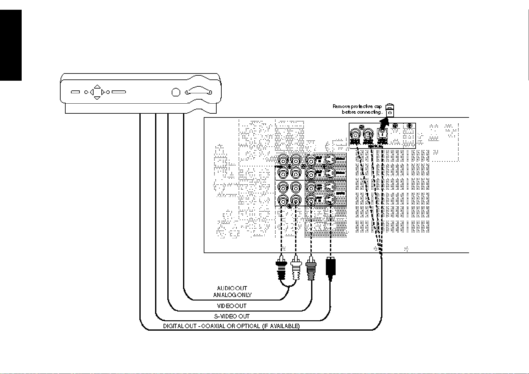
Remove protective cap
before connecting.
VIDEO4 6CH.INPUT
CENTER
SUBWOOFER
SURROUND
AUDIO OUT
ANALOG ONLY
VIDEO OUT
S-VIDEO OUT
DIGITAL OUT - COAXIAL OR OPTICAL
Page 23

Chapter One : Connecting Your Devices Audio-Video Receiver KRF-X9992D
Connecting Your DVD Player, continued
Connections
Do not plug in the receiver to AC power until you
have connected all your devices.
This section focuses on the connections from your
DVD player to the KRF-X9992D. Please refer to your
DVD player’s instructions for more detail about its
connection jacks and capabilities.
The instructions in this section show one of several
possible variations on connecting your DVD player.
For further assistance on optional configurations,
contact the store where you purchased your receiver.
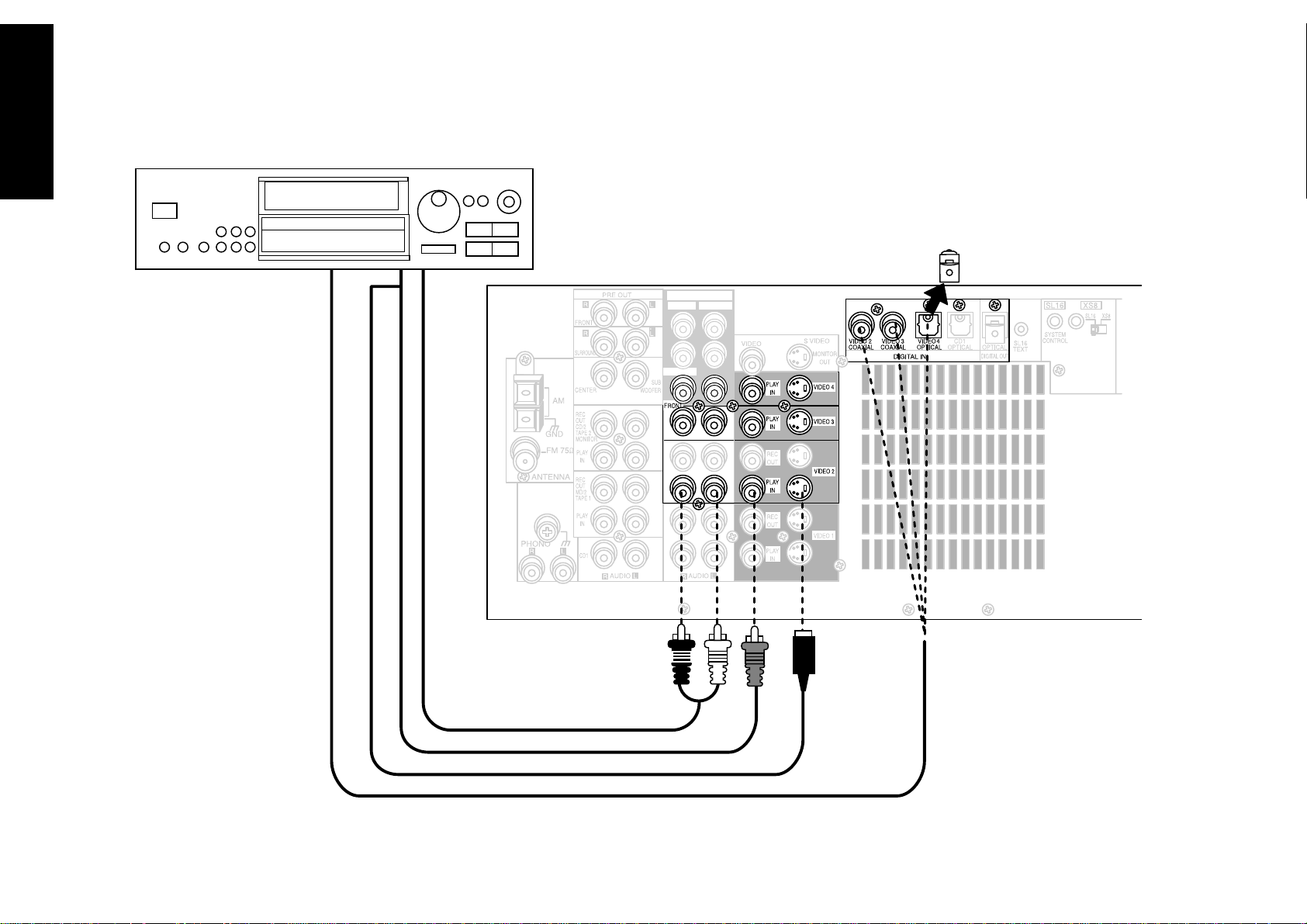
To Connect a DVD Player:
1. Review the information under “Before You
Begin” on page␣ 1. It contains important notes
about the types of video connections you can
make.
2. Look at the digital cable that came with your
DVD player. Use the table below to choose a jack
set:
If your digital
cable is...
optical VIDEO4
coaxial VIDEO2 or 3
Note that the jack sets are linked, even though
they are not adjacent. You must connect all of
the cables from your DVD player to a linked jack
set. For example, if you connect the analog cables
to VIDEO2 and the digital optical cable to
VIDEO4,␣ your DVD player will not work correctly.
Choose this jack
set...
3. Connect the audio and video cables from the
DVD’s Audio and Video jacks to the receiver’s
PLAY IN jacks as shown to the left.
4. Connect the digital cable (either coaxial or
optical) from the DVD’s digital jack to the
appropriate digital jack on the receiver as shown
to the left.
The illustration shows two digital connections,
one for coaxial connection and one for optical
connection. Your DVD player supports one or
the other of these connection methods—do not
connect both.
If you use the optical digital cable, be sure to
remove the protective cover from the optical jack
before connecting.
5. Go to “Noting Your Devices” on page␣ 3 and note
which jacks you used to connect your DVD
player. In addition, note the brand name and
model number of the DVD player.
17
DTS disclaimer clause
DTS Digital Surround™ is a discrete 5.1 channel digital audio format available on CD, LD, and DVD software which consequently cannot be decoded and played back
inside most CD, LD, or DVD players. For this reason, when DTS-encoded software is played back through the analog outputs of the CD, LD, or DVD player, excessive
noise will be exhibited. To avoid possible damage to the audio system, proper precautions should be taken by the consumer if the analog outputs are connected
directly to an amplification sysem. To enjoy DTS Digital Surroud™ playback, an external 5.1 channel DTS Digital Surround™ decoder system must be connected to the
digital output (S/PDIF, AES/EBU, or TosLink) of the CD, LD or DVD player.
Page 24
Chapter One : Connecting Your Devices Audio-Video Receiver KRF-X9992D
Connections
18
DVD player
Connecting Your DVD Player Through a Surround Processor
Surround Processor
SUBWOOFER
CENTER
S-VIDEO OUT
VIDEO OUT
VIDEO4 6CH.INPUT
CENTER
SUBWOOFER
VIDEO 4
INPUT
SURROUND
FRONT
SURROUND
6 CH
2 CH
Page 25

Chapter One : Connecting Your Devices Audio-Video Receiver KRF-X9992D
Connecting Your DVD Player Through a Surround Processor, continued
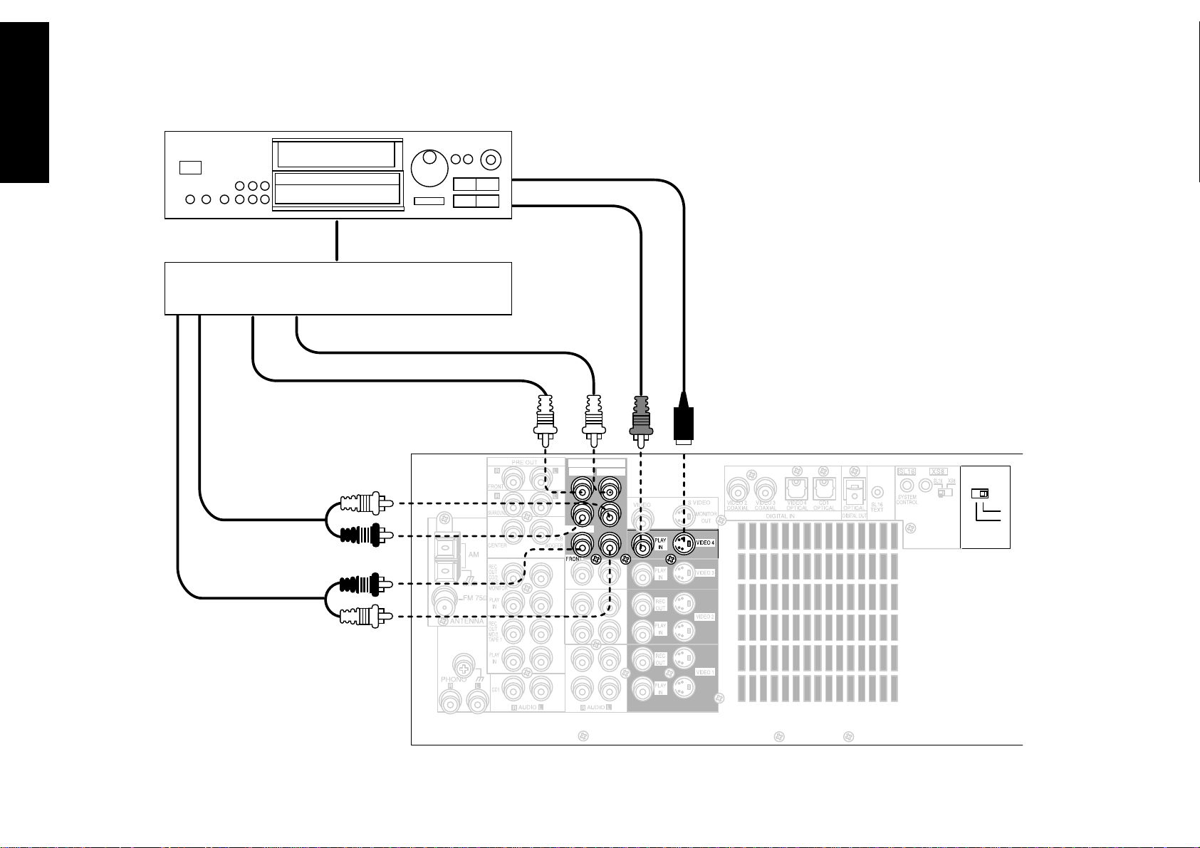
To Connect a DVD Player through a
surround processor:
Do not plug in the receiver to AC power until you
have connected all your devices.
You must purchase a multi-channel surround
processor if you want to play DTS DVD discs with
this receiver.
These instructions describe how to connect a DVD
player through a multi-channel surround processor.
If you do not plan to play any DTS DVD discs, you
do not need to connect a surround processor. See
“Connecting You DVD Player” on page 17. Please
refer to your DVD player’s instructions for more
detail about its connection jacks and capabilities.
The instructions in this section show one of several
possible variations on connecting your DVD player.
For further assistance on optional configurations,
contact the store where you purchased your receiver.
1. Review the information under “Before You
Begin” on page␣ 1. It contains important notes
about the types of video connections you can
make.
2. Connect the digital cable from the DVD player’s
Digital OUT jack to the surround processor’s
Digital jack.
3. Connect the audio cables from the surround
processor (FRONT, CENTER, SURROUND,
SUBWOOFER) to the receiver’s VIDEO 4 6CH.
INPUT jacks as shown to the left.
4. For the video cable connection, you must use the
VIDEO 4 jack set.
5. To activate the surround processor connections,
you need to move VIDEO 4 INPUT switch to
6CH position before turning the system on.
6. Go to “Noting Your Devices” on page␣ 3 and note
which jacks you used to connect your DVD
player. In addition, note the brand name and
model number of the DVD player.
Connections
19
Page 26
Chapter One : Connecting Your Devices Audio-Video Receiver KRF-X9992D
Connections
20
Connecting Your MD Recorder or Primary Tape Deck
Remove protective cap
before connecting.
VIDEO4 6CH.INPUT
CENTER
SUBWOOFER
SURROUND
PLAY OUT (ANALOG)
RECORD IN (ANALOG)
DIGITAL RECORD IN (OPTICAL)
SYSTEM CONTROL CABLE - KENWOOD ONLY
Page 27

Chapter One : Connecting Your Devices Audio-Video Receiver KRF-X9992D
Connecting Your MD Recorder or Primary Tape Deck, continued
Connections
Do not plug in the receiver to AC power until you
have connected all your devices.
This section focuses on the connections from your
MD recorder or tape deck to the KRF-X9992D.
Please refer to your MD recorder or tape deck’s
instructions for more detail about its connection
jacks and capabilities.
Each set of instructions in this section shows one of
several possible variations on connecting your MD
recorder or tape deck. For further assistance on
optional configurations, contact the store where you
purchased your MD recorder or tape deck.
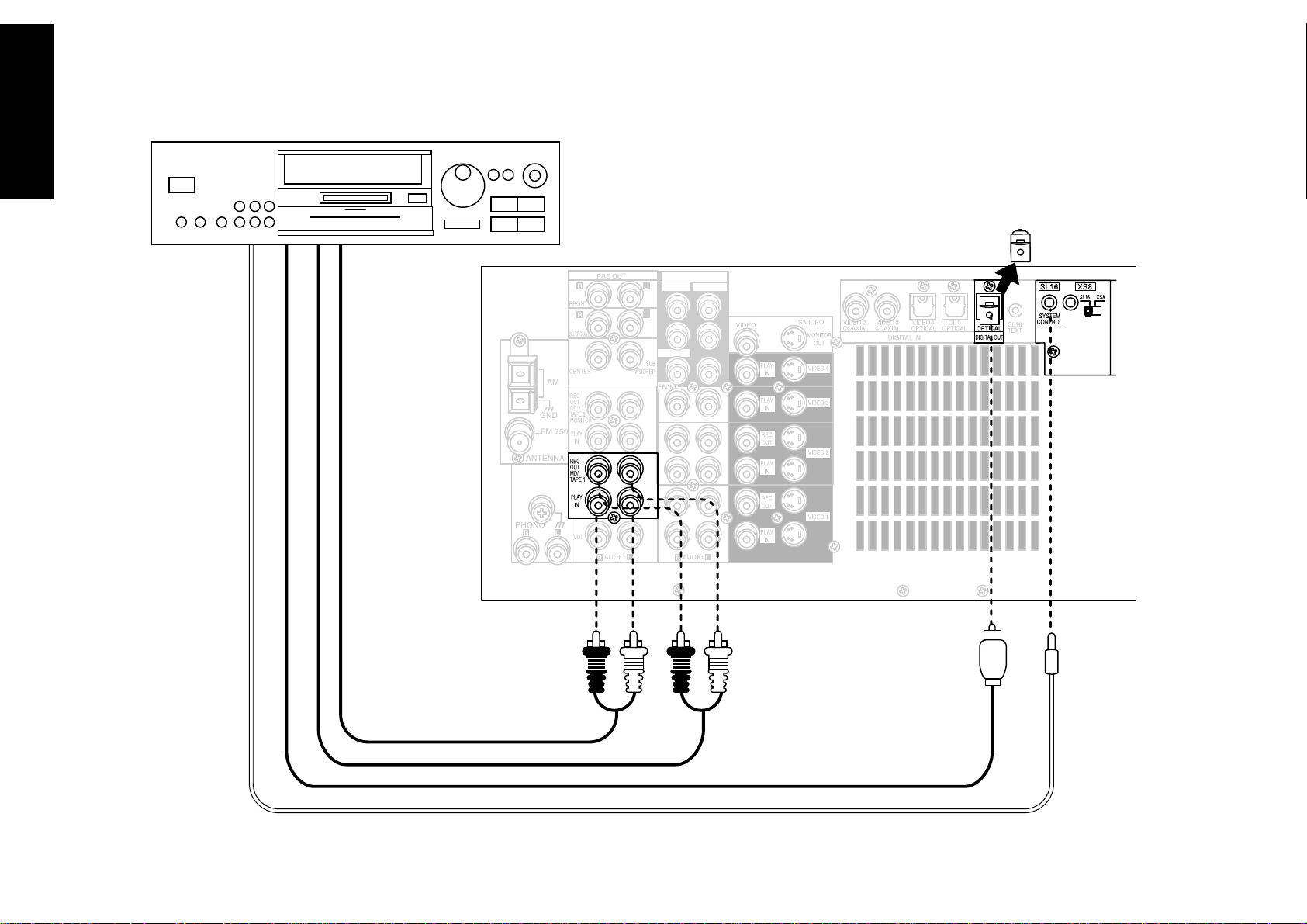
To Connect an MD Recorder:
1. Connect the audio cable from the MD recorder’s
Play OUT jacks to the receiver’s MD/TAPE 1 PLAY
IN jacks as shown to the left.
2. Connect the audio cable from the MD recorder’s
Rec IN jacks to the receiver’s MD/TAPE 1 REC
OUT jacks, as shown to the left.
3. Remove the cover from the receiver’s OPTICAL
DIGITAL OUT jack, then connect the optical
digital cable from the MD recorder’s REC IN jack
to the receiver’s OPTICAL DIGITAL OUT jack as
shown to the left.
You only need to connect to the digital out jack
if you will be recording from sources that are
connected to a digital in jack, such as a CD or
DVD player.
4. If you are connecting a Kenwood MD recorder,
connect the system control cable from the MD
recorder to the receiver. Be sure that the SL16/
XS8 switch on the receiver is set to SL16. (MD
recorder only supports SL16 system control
mode.)
If you are connecting more than one Kenwood
device with a system control cable, see “What if I
Have Several Kenwood Devices (System Control
Chaining)?” on page␣ 30.
To Connect a Primary Tape Deck:
1. Connect the audio cable from the tape deck’s
Play OUT jacks to the receiver’s MD/TAPE 1 PLAY
IN jacks as shown to the left.
2. Connect the audio cable from the tape deck’s Rec
IN jacks to the receiver’s MD/TAPE 1 REC OUT
jacks as shown to the left.
3. If you are connecting a Kenwood tape deck with
system control, connect the system control cable
from the tape deck to the receiver. Be sure that
the SL16/XS8 switch on both the tape deck and
the receiver is set appropriately.
If you are connecting more than one Kenwood
device with a system control cable, see “What if I
Have Several Kenwood Devices (System Control
Chaining)?” on page␣ 30 of the Connection and
Setup Guide.
4. Go to “Noting Your Devices” on page␣ 3 and note
which jacks you used to connect your tape deck.
In addition, note the brand name and model
number of the tape deck.
To Connect a Secondary Tape Deck
See “Connecting Your Secondary CD Player or Tape
Deck” on page␣ 22.
21
5. Go to “Noting Your Devices” on page␣ 3 and note
which jacks you used to connect your MD
recorder. In addition, note the brand name and
model number of the MD recorder.
Page 28
Chapter One : Connecting Your Devices Audio-Video Receiver KRF-X9992D
Connections
22
Connecting Your Secondary CD Player or Tape Deck
VIDEO4 6CH.INPUT
CENTER
SUBWOOFER
SURROUND
CD OUTPUT OR TAPE PLAY OUT
TAPE RECORD IN
Page 29

Chapter One : Connecting Your Devices Audio-Video Receiver KRF-X9992D
Connecting Your Secondary CD Player or Tape Deck, continued
Connections
Do not plug in the receiver to AC power until you
have connected all your devices.
This section focuses on the connections from your
CD player or tape deck to the KRF-X9992D. Please
refer to your CD player or tape deck’s instructions
for more detail about its connection jacks and
capabilities.
Each set of instructions in this section shows one of
several possible variations on connecting your CD
player or tape deck. For further assistance on
optional configurations, contact the store where you
purchased your CD player or tape deck.
Do not connect a system control cable from any
unit connected via the CD2/TAPE2 MONITOR jacks.
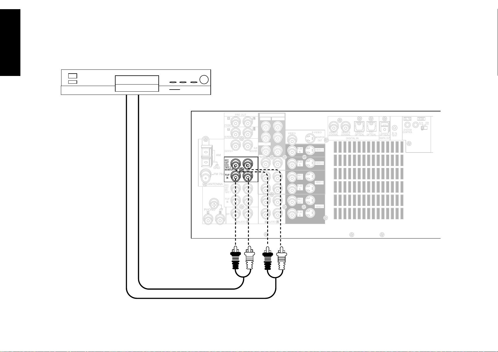
To Connect a Secondary CD Player:
1. Connect the audio cables from the CD player’s
audio jacks to the receiver’s CD2/TAPE 2 MONITOR PLAY IN jack set as shown to the left.
Do not connect the system control cable from
the second CD player, even if it supports system
control.
2. Go to “Noting Your Devices” on page␣ 3 and note
which jacks you used to connect your CD player.
In addition, note the brand name and model
number of the CD player.
If you connect a second tape deck, you cannot
connect a second CD player.
To Connect a Secondary Tape Deck:
1. Connect the audio cable from the tape deck’s
Play OUT jacks to the receiver’s CD2/TAPE 2
MONITOR PLAY IN jacks.
2. Connect the audio cable from the tape deck’s Rec
IN jacks to the receiver’s CD2/TAPE 2 MONITOR
REC OUT jacks.
Do not connect the system control cable from
the second tape deck, even if it supports system
control.
3. Go to “Noting Your Devices” on page␣ 3 and note
which jacks you used to connect your tape deck.
In addition, note the brand name and model
number of the tape deck.
If you connect a second CD player, you cannot
connect a second tape deck.
23
Page 30
Chapter One : Connecting Your Devices Audio-Video Receiver KRF-X9992D
Connections
24
Connecting Your Laser Disc Player (with AC-3 RF Output)
VIDEO4 6CH.INPUT
CENTER
SUBWOOFER
SURROUND
AUDIO OUT
VIDEO OUT
S- VIDEO OUT
AC-3 RF OUT
COAX. OR OPTICAL DIGITAL OUT
DIGITAL OUTPUT
COAX.
RF INPUT
AC-3 RF
DIGITAL OUT
DIGITAL INPUT
COAX. OPT.
Remove protective cap
before inserting
DC IN
RF
DEMODULATOR
Page 31

Chapter One : Connecting Your Devices Audio-Video Receiver KRF-X9992D
Connecting Your Laser Disc Player (with AC-3 RF Output), continued
Connections
Do not plug in the receiver to AC power until you
have connected all your devices.
You must purchase an RF Demodulator (DEM-
9991D) if you plan to operate a player with a Dolby
Digital (AC-3) RF Output with this receiver.
These instructions describe how to connect a laser
disc player with an AC-3 RF Output. If your laser
disc player does not have an AC-3 RF output, see
“Connecting Your Laser Disc Player (without AC-3
RF Output)” on page␣ 26. Please refer to your laser
disc player’s instructions for more detail about its
connection jacks and capabilities.
The instructions in this section show one of several
possible variations on connecting your laser disc
player. For further assistance on optional configurations, contact the store where you purchased your
receiver.
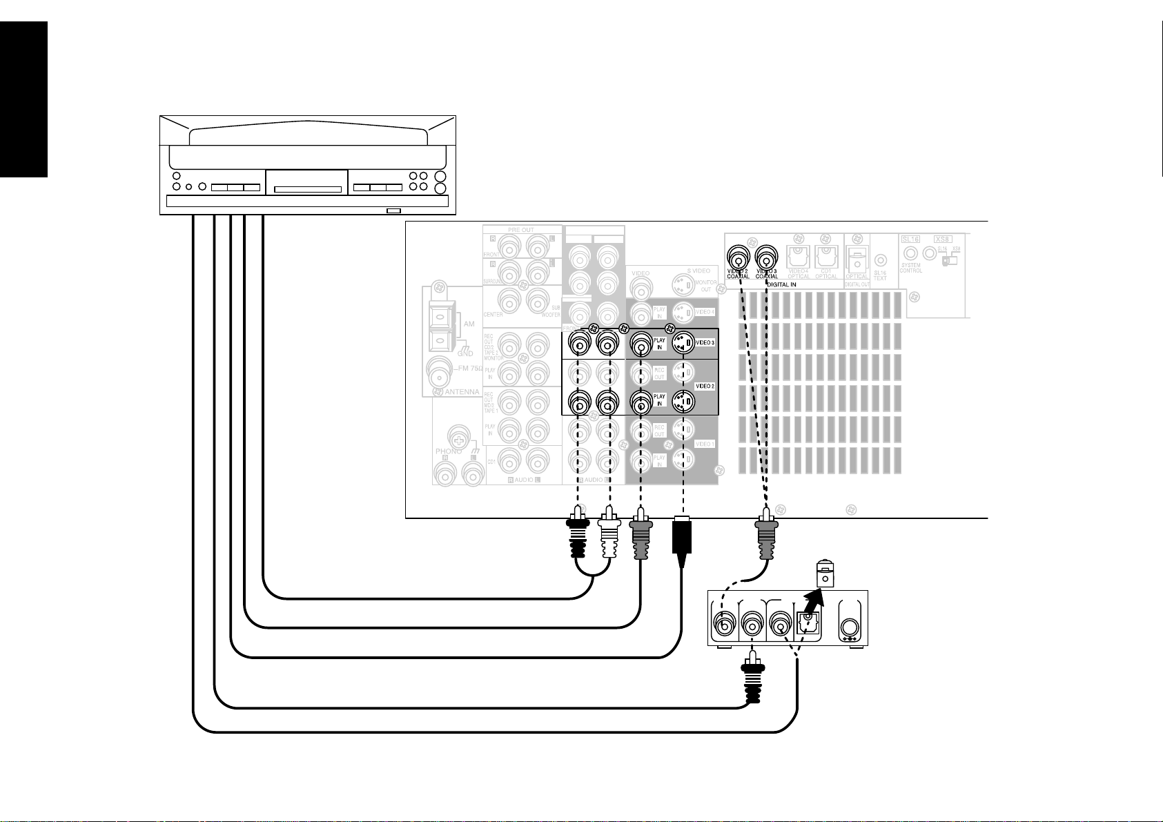
To Connect an AC-3 RF Output Laser
Disc Player:
1. Review the information under “Before You
Begin” on page␣ 1. It contains important notes
about the types of video connections you can
make.
2. Connect the audio cables from the laser disc
player’s Audio OUT jacks to the receiver’s AUDIO
jacks (VIDEO2 or VIDEO3 PLAY IN) as shown to
the left.
3. For the video cable connection, you must use the
VIDEO2 or VIDEO3 jack set, as that is the set
with a coaxial digital connection.
Do not connect the digital cable (coaxial or
optical) yet; it must be connected via the demodulator as described in the following steps.
4. Connect the AC-3 RF coaxial cable from the laser
disc player’s AC-3 RF OUT jack to the demodulator’s RF INPUT AC-3 RF jack as shown to the left.
5. Connect the digital cable (either coaxial or
optical) from the laser disc player’s digital jack to
the appropriate DIGITAL INPUT jack on the
demodulator as shown to the left. Set the switch
on the front of the DEM-9991D to the type of
connection you made.
6. Connect the coaxial digital cable from the
demodulator’s DIGITAL OUTPUT COAX. jack to
the receiver’s VIDEO2 or VIDEO3 COAXIAL jack.
7. Connect the demodulator’s supplied 12V AC
adapter to the DC IN jack on the demodulator.
Do not plug the adapter into the wall until you
have finished making all connections to the
receiver.
8. Go to “Noting Your Devices” on page␣ 3 and note
which jacks you used to connect your laser disc
player. In addition, note the brand name and
model number of the laser disc player.
25
Page 32

Chapter One : Connecting Your Devices Audio-Video Receiver KRF-X9992D
Connecting Your Laser Disc Player (without AC-3 RF Output)
Connections
26
Note that video device jacks are linked to specific digital jacks. For example, if you connect a laser
disc player with a digital optical cable, you should connect the analog cables to the VIDEO 4
video device jacks and the digital cable to the VIDEO4 digital optical jack.
Remove protective cap
before inserting
VIDEO4 6CH.INPUT
CENTER
SUBWOOFER
SURROUND
AUDIO OUT
VIDEO OUT
S- VIDEO OUT
DIGITAL OUT (COAXIAL OR OPTICAL)
Page 33

Chapter One : Connecting Your Devices Audio-Video Receiver KRF-X9992D
Connecting Your Laser Disc Player (without AC-3 RF Output), continued
Connections
Do not plug in the receiver to AC power until you
have connected all your devices.
These instructions describe how to connect a laser
disc player with a PCM Digital Output. If your
player has a Dolby Digital (AC-3) RF Out, see
“Connecting Your Laser Disc Player (with AC-3 RF
Output)” on page␣ 24. This configuration does not
allow Dolby Digital laser discs to be played. Please
refer to your laser disc player’s instructions for more
detail about its connection jacks and capabilities.
The instructions in this section show one of several
possible variations on connecting your laser disc
player. For further assistance on optional configurations, contact the store where you purchased your
receiver.
To Connect a PCM Digital Output Laser
Disc Player:
1. Review the information under “Before You
Begin” on page␣ 1. It contains important notes
about the types of video connections you can
make.
2. Look at the digital connection on your laser disc
player. Use the table below to choose a jack set:
If your digital
cable is...
optical VIDEO4
coaxial VIDEO2 or 3
Note that the jack sets are linked, even though
they are not adjacent. You must connect all of
the cables from your laser disc player to a linked
jack set. If you connect the analog cables to
VIDEO2 and the digital optical cable to
VIDEO4,␣ your laser disc player will not work
correctly.
3. Connect the audio cables from the laser disc
player’s Audio OUT jacks to the receiver’s AUDIO
jacks as shown to the left.
Choose this jack
set...
4. Connect the video cable from the laser disc
player’s Video OUT jack to the receiver’s VIDEO
PLAY IN jack as shown to the left.
5. Connect the digital cable (either coaxial or
optical) from the laser disc player’s digital jack to
the appropriate digital jack on the receiver as
shown to the left. Your laser disc player supports
only one of the digital connection methods—do
not connect both.
If you use the optical digital cable, be sure to
remove the protective cover from the optical jack
before connecting.
6. Go to “Noting Your Devices” on page␣ 3 and note
which jacks you used to connect your laser disc
player. In addition, note the brand name and
model number of the laser disc player.
27
Page 34

Chapter One : Connecting Your Devices Audio-Video Receiver KRF-X9992D
Connections
28
Connecting Your Turntable/Record Player
GROUND
Do not plug in the receiver to AC power until you
have connected all your devices.
This section focuses on the connections from your
turntable/record player to the KRF-X9992D. Please
refer to your turntable/record player’s instructions
for more detail about its connection jacks and
capabilities.
To Connect a Turntable/Record Player:
1. Connect the audio cables from the turntable
audio output jacks to the receiver’s PHONO R
and L jacks.
2. If your turntable includes a ground cable,
connect the ground cable to the receiver’s
PHONO ground jack.
3. Go to “Noting Your Devices” on page␣ 3 and note
which jacks you used to connect your turntable.
In addition, note the brand name and model
number of the turntable.
AUDIO OUT
Page 35

Chapter One : Connecting Your Devices Audio-Video Receiver KRF-X9992D
Connecting a Camcorder or Additional VCR
This section focuses on the connections from your
camcorder or VCR to the front of the KRF-X9992D.
Please refer to your camcorder or VCR’s instructions
for more detail about its connection jacks and
capabilities.
These instructions describe how to connect a
camcorder or VCR quickly and probably temporarily
to the front of the receiver. If you want a less
cluttered and more permanent connection, see “Can
I Connect an Additional VCR Permanently?”, below.
To Connect a Camcorder or Additional
VCR:
Connect the audio and video cables from the
camcorder or VCR’s Audio and Video jacks to the
receiver’s front panel jacks as shown to the left.
Can I Connect an Additional VCR
Permanently?
Yes. To do so, follow the instructions under “To
Connect a Secondary VCR:” on page␣ 13.
Connections
29
AUDIO OUT
VIDEO OUT
S-VIDEO OUT
(or additional VCR)
Page 36

Chapter One : Connecting Your Devices Audio-Video Receiver KRF-X9992D
What if I Have Several Kenwood Devices (System Control Chaining)?
Kenwood provides convenient control of the entire
Connections
system via two control modes:
• SL16, which allows you to connect SL16 devices
only
• XS8, which allows you to connect XS, XS8, and
XR devices
You cannot mix SL16 and XS8 settings. All devices
connected via system control cables must use the
same setting.
An Example of SL16 Chained
Connections:
[SL16] [XS8]
30
[SL16] [XS] [XS8]
[SL16]
[SL16] [XS] [XS8] [XR]
[XS]
Receiver
CD Player
MD Recorder
Tape Deck
Record Player
SYSTEM
CONTROL
cord
To switch between the two modes :
1. Slide the selector switch (shown below) from
SL16 (the factory-set default) to XS8.
2. Turn the receiver’s power switch off, and on
again.
System Control connection allows you to:
• See the current status of the selected source
device, such as Play or Stop (SL16 devices only).
• control connected devices via the remote
• switch the receiver’s input automatically to a
connected device when you start playback from
that device
• synchronize recording a CD automatically when
you start playback from the connected CD player
Make sure the units are connected to the correct
jacks on the receiver—for example, no device
connected to the CD2/TAPE 2 MONITOR jacks can
use a system control cable.
Some CD players and cassette decks do not support
the SL16 system control mode. Do not include these
devices in a set of SL16 chained connections; where
appropriate, use the XS8 mode instead.
Do not mix connections of the two modes: if a
device does not support the mode you are using for
chaining, do not connect that device.
Do not connect system control cables to any device
not specified by Kenwood. Using system control
functions with a device that does not support them
can damage the device.
Make sure system control plugs are firmly seated in
the appropriate jacks.
An Example of XS8 Chained
Connections:
[SL16] [XS8]
[SL16] [XS] [XS8]
[SL16]
[SL16] [XS] [XS8] [XR]
[XS]
Receiver
CD Player
MD Recorder
Tape Deck
Record Player
SYSTEM
CONTROL
cord
Page 37

Chapter One : Connecting Your Devices Audio-Video Receiver KRF-X9992D
Connecting the Antennas
Connections
AM Loop Antenna
Your new receiver comes with an AM loop antenna
for AM radio reception. To connect the AM antenna:
1. Insert the antenna loop into the base and
position the loop.
2. Open the receiver’s antenna terminal levers.
3. Insert the antenna’s wires into the terminal as
shown above.
4. Close the antenna terminal levers to lock the
wires in place.
5. Adjust the antenna loop as necessary to improve
reception.
FM Indoor Antenna
Your new receiver also comes with an FM indoor
antenna for FM radio reception. To connect the FM
antenna:
1. Attach the antenna sheath to the pole in the
center of the receiver’s FM antenna jack, as
shown above. When you attach the sheath for the
first time, you may need to exert quite a bit of
pressure.
2. Adjust the antenna as necessary to improve
reception.
3. Tack the looped end of the antenna in the
location that provides the best reception.
FM Outdoor Antenna
Kenwood recommends a permanently installed
outdoor FM antenna for best FM reception. To
connect an outdoor FM antenna:
1. Connect the antenna wire to a standard,
commercially available antenna adapter as
shown above.
2. Connect the adapter to the receiver’s FM antenna
jack.
What if I Have Cable Radio?
If you have cable radio, contact your cable provider
for assistance with connecting to the KRF-X9992D.
31
To prevent hum interference, keep the AM antenna
wires away from speaker wires, AC power cords, the
TV chassis, and the receiver.
Page 38

Chapter Two : Setting Up PowerTouch Audio-Video Receiver KRF-X9992D
Your new PowerTouch controls your new receiver
and can be set up to control most components
attached to it. PowerTouch appears and functions a
little differently from traditional remotes. It incorporates sophisticated engineering and design to
allow you to simply touch the screen to press
buttons and operate controls. You can touch the
screen with your finger or with the stylus stored at
the top of the PowerTouch.
Remote Setup
Chapter Two: Setting Up PowerTouch
Because it can control so many different devices, it
presents a separate set of controls for each device on
an LCD screen. Touch an icon on the screen to
access further menus or controls for devices.
Only devices previously identified and connected to
the receiver will appear as icons on the display
screen. If you are “missing” an icon on your display
screen, make sure you have identified the device to
PowerTouch. This chapter describes identifying
devices to PowerTouch.
Installing the Batteries
This chapter contains the following sections:
Installing the Batteries page 32
Calibrating the Touch Screen page 33
Navigating PowerTouch Interface page 34
Setting Up Speakers page 34
Identifying Devices For PowerTouch Control page 37
Storing Radio Stations in Memory page 40
Before you can set up any PowerTouch item, you
32
need to install batteries.
• The batteries that came with your new PowerTouch are intended for you to use for an operation check—they may not last as long as ordinary
batteries. We recommend replacing them with
alkaline batteries for normal use.
To install the batteries:
1. Press down and back on the battery cover to
remove it.
2. Insert six AA batteries as shown below:
3. Close the cover.
If you use PowerTouch outside of it’s range (see
“How is PowerTouch Powered?” on page␣ 5 of the
Users’ Guide) PowerTouch’s display may show
incorrect information.
When your batteries begin to run low, PowerTouch
displays a Low Battery message. Clear the message
by touching check mark icon (
batteries as described here.
Maximize the life of your batteries by turning the
Backlight off if you are not trying to use PowerTouch
in the dark. For more information on the Backlight,
see the Users’ Guide.
If you cannot see anything on the screen after
replacing batteries, try to adjust the screen contrast.
See 61 page of the Users’ Guide.
Under some circumstances (for example, if you plan
to use multiple remotes), you can set PowerTouch
up to communicate via a hardwired cable and be
powered by a AC adapter/wall cube. If you choose
this setup option, you should contact the store
where you purchased your receiver.
) and replace all 6
Page 39

Chapter Two : Setting Up PowerTouch Audio-Video Receiver KRF-X9992D
Calibrating the Touch Screen
After you install the batteries or reset PowerTouch,
you need to calibrate the touch screen. The touch
screen responds to pressure from the included stylus
or your finger:
If you are replacing batteries and complete the
battery replacement within 3 minutes, you do not
need to calibrate the screen; calibration is stored in
memory.
If the screen’s performance begins to change, you can
recalibrate it without resetting PowerTouch by
pressing
more information about accessing this menu, see
“Identifying Devices For PowerTouch Control” on
page␣ 37.
on the Setup Preference menu. For
To calibrate the touch screen, use the stylus to touch
the center of each of the calibration points displayed
When you touch each calibration point, you should
hear a beep and see the next point, indicating that
area of the screen is now calibrated. If you do not
hear a beep, touch the calibration point until you do.
The touch screen is sensitive to pressure, not to
movement. Press firmly but gently on any touch screen
element. The screen will not respond if you simply
brush the stylus or your finger along the surface.
Resetting PowerTouch
If you want to reconfigure PowerTouch, you can
reset it. You do not need to do this unless you
experience a problem.
1. Open the cover.
2. Use the stylus to press the blue button at the
bottom of the battery case:
The items you set up in this chapter will remain in
PowerTouch. If you want to make it to the factory–
set default condition, please follow the instructions
on page 78 of the Users’ Guide.
Remote Setup
33
Page 40

Chapter Two : Setting Up PowerTouch Audio-Video Receiver KRF-X9992D
Navigating PowerTouch Interface
PowerTouch presents a “map” of the menus you
have available:
Remote Setup
34
For convenience, PowerTouch zooms in on and
displays only a portion of this map at a time. The
boxes on the illustration above surround what you
will see on the screen for each area of the map.
There are three ways to navigate this map:
• Use the stylus or your finger to touch a button
on the Main menu. The touch screen will “fly”
you over the map to that menu. Touch
return to the Main menu.
to
• Push the joystick in the direction you want to go.
The touch screen will “fly” you over the map to
the menu. You can only use the joystick this way
when you are at the Main menu. To return to the
Main menu, always push the joystick “down”
(toward the volume button).
• Use the stylus or your finger to touch a Quick
Access button (the blue buttons on the left side
of the screen). The touch screen will jump
immediately to that menu. Touch
to the Main menu.
Ouick Tour PowerTouch includes a Quick Tour to
familiarize you with the options available and how to
access them. You may want to run the Quick Tour
before you begin setting up devices. To start the Quick
Tour, use the stylus or your finger to touch
For the rest of this chapter, you will be using the
various settings on the Setup menu. The Setup menu
includes the following settings and their subsettings:
• Preference, which contains the following:
• IR (“Identifying Devices For PowerTouch
Control” on page␣ 37)
This menu setting allows you to identify your
connected devices to PowerTouch.
to return
.
• Input (KRF-X9992D Users’ Guide)
• Surround (“Setting Up Speakers” on this page)
These menu settings allow you to set up speakers
and subwoofer, set the distance from your
speakers to the listening area, determine speaker
levels, and set the surround speaker type. The
Next button on each screen takes you to the next
group of settings (i.e., pressing Next at SP
Selection takes you to SP Distance without
having to go back to the menu).
• Macro (KRF-X9992D Users’ Guide)
This menu setting allows you to create custom
macros that perform several operations (such as
turning a device on, changing the receiver’s
input, and changing a TV station) with a single
touch.
Before you can begin using the receiver to control
your home entertainment system, you must set up
PowerTouch to operate your speakers effectively.
There are four areas of speaker setup:
Setting Up Speakers
• SP Selection
• SP Distance
• SP Level
• Bass Peak Level
You can set up your speakers in the order presented
here (via the Next button) or individually, selecting
each option from the Surround menu.
The receiver must be on, speakers must be connected,
and Speaker A on the front panel must be turned on
before you can set up speakers.
Page 41

Chapter Two : Setting Up PowerTouch Audio-Video Receiver KRF-X9992D
To begin setting up speakers:
1. Touch
Setup menu.
2. Touch on the Setup settings.
on the Main menu to access the
SP Selection
1. Touch on the Setup Surround
menu to open the Speaker Selection menu:
2. Kenwood provides two ways to set up your
speakers:
Quick Setup: Use this method for a simplified
setup where you identify whether a speaker is
present and let the receiver automatically determine the appropriate speaker settings.
a. Aim PowerTouch at the receiver. If the speaker
is present, touch the speaker button until
“Yes” appears in the button. (SW=subwoofer,
C=center, LS=left surround and RS=right
surround):
If you selected Yes for the subwoofer, all of
the bass below 80Hz is removed from other
speakers in your system and is sent to the
subwoofer in all listening modes. This
improves your speakers’ power handling and
reduces overall distortion.
b. Touch
c. Touch
or touch
Custom setup: Use this method for a more
customized setup where you determine more of
the speaker settings, such as the bandwidth of the
sound sent to each speaker. Custom setup configures the following: SW=subwoofer, L=left front,
R=right front, C=Center, LS=left surround and
RS=right surround.
to save your settings.
to move to the next speaker setting
to return to the Surround menu.
a. Touch
b. Aim PowerTouch at the receiver and touch the
speaker button until the correct setting
appears (see below).
The left and right front buttons and the left
and right surround buttons are linked; if you
touch one, you change the settings for both.
• Off means you are not using the speaker.
(Not available for front speakers). If no
subwoofer is connected, all bass below
80Hz is sent to left and right front speakers.
• On means that you are using the speaker.
(Only available for subwoofer).
• Select Nml (= Normal) if the speaker is
not capable of producing clean, deep bass
energy at output levels that match those
produced by a typical powered subwoofer.
All bass below 80Hz in that channel is
removed from that speaker and is sent to
the subwoofer in all listening modes. Most
speakers should be considered Nml.
• Select Lrg (= Large) if the speaker is capable
of producing clean, deep bass energy at
output levels that match those produced by
a typical powered subwoofer. All bass below
on the Speaker Selection menu:
Remote Setup
35
Page 42

Chapter Two : Setting Up PowerTouch Audio-Video Receiver KRF-X9992D
Remote Setup
c. If you set your left and right front speakers to
36
80Hz in that channel is left in that speaker
in all listening modes. Full-range speakers
capable of this level of bass performance are
very uncommon, and are almost always too
large to be used as center or surround
speakers.
If you set your left and right front speakers
to Lrg and have a subwoofer in the system,
the subwoofer will only receive bass in
Stereo mode and during Dolby Digital and
MPEG programs. In Dolby Pro Logic,
Dolby 3 Stereo, and DSP modes, the
subwoofer will not receive any signal at all.
Lrg and want to send bass to the subwoofer in
all Listen modes, touch
appears above the button. In Dolby Pro Logic,
Dolby 3 Stereo, and DSP modes SW Re-Mix
mixes some of the bass from your left and
right front speakers back into your subwoofer.
If you set your left and right front speakers to
Nml, SW Re-Mix does not function.
until “On”
SP Distance
1. Measure the distance from each speaker to the
seat you most often use and note it below:
Speaker
left front
center
right front
left surround
right surrond
subwoofer
2. If you are not already there, touch
on the Setup Surround menu to open the
Speaker Distance menu:
Distance (ft or m)
SP Level
In this step you will use your ears to balance the
volume level of all the system’s speakers except the
subwoofer for your room and listening position. (To
set the subwoofer level, see “Setting the Subwoofer
Level” on page␣ 37.) When all the speakers are set at
the same volume level, your system will create a more
realistic, spacious surround sound environment.
1. Eliminate as many external noise sources as
possible.
2. Sit in the place where you and your guests are
most likely to sit while watching movies or
listening to music.
3. If you are not already there, touch
on the Setup Surround menu to open the
Speaker Level menu:
d. Touch
e. Touch
or touch
If your front speakers are set to Nml, you can only set
your center and surround speakers to Nml (or OFF).
If you turn off the subwoofer, your front speakers
are automatically set to Lrg. You may not set them
to Nml.
to save your settings.
to move to the next speaker setting
to return to the Surround menu.
3. Touch or to set the distance for the left
front speaker.
4. Touch
5. Repeat steps 3 and 4 for each speaker.
6. Touch
touch
or to select the next speaker.
to move to the next speaker setting or
to return to the Surround menu.
4. Touch until the Test Tone display reads
“Manu”.
5. The receiver’s master volume will become 0 dB,
and test noise will play from the left front
speaker. Please note that the test tone is quite
loud.
Page 43

Chapter Two : Setting Up PowerTouch Audio-Video Receiver KRF-X9992D
6. Touch
7. Carefully listen to the volume level of the test
noise. If the noise is a different volume than the
noise from the left front speaker, use
to adjust the volume so that the volume matches
the volume from the left front speaker. (Do not
be concerned with the volume number readout
on the Level display—this is for reference
purposes only. Use your ears to determine if the
two speakers are playing at the same volume).
8. Repeat steps 6 and 7 until all the system’s speakers
(except the subwoofer) play at the same volume.
9. To confirm the volume levels, touch
Test Tone display reads “Auto.” The test noise will
automatically cycle between all of the speakers.
Fine-tune the channel levels as necessary.
10. When all the channels sound like they’re the
same volume, you’ve balanced your system.
11. To turn off the test noise, touch
Test Tone display reads “Off.”
Setting the Subwoofer Level: Because of the
way humans hear, the test noise the Speaker
Level menu sends through the subwoofer will
not sound as loud as it really is. (The Speaker
Level menu subwoofer test noise is designed to
or to select the next speaker.
or
until the
until the
be used with a sound pressure level meter for
balancing.) Because of this, you cannot use that
test noise to properly calibrate the level of your
subwoofer by ear. To set the subwoofer level,
listen to familiar music or films that have strong
bass content and adjust the subwoofer level until
it sounds balanced with the rest of the speakers.
12.Touch
touch
to move to the next speaker setting or
to return to the Surround menu.
Bass Peak Level
Because of the way humans hear, the test noise the
Speaker Level menu sends through the subwoofer
will not sound as loud as it really is. (This Speaker
Level menu subwoofer test noise is designed to be
used with a sound pressure level meter for
balancig.) Because of this, you cannot use that test
noise to properly calibrate the level of your
subwoofer by ear. The PowerTouch contains a
separate setup menu for the subwoofer.
To set the subwoofer level:
1. If you are not already there, touch
on the Setup Surround menu to open the Bass
Peak Level memu.
2. Touch until the Test Tone display reads
“On”.
3. Test noise will play from the subwoofer. Carefully listen to the volume level of the noise.
4. Use the left (
raise the volume until the sound will be almost
distorted.
5. Touch
6. Touch
7. Touch
again to return to the Main menu. You are now
finished setting up the speakers.
to return to the Setup menu. Touch it
) or right ( ) Level arrows to
to save your settings.
to return to the Surround menu.
Remote Setup
37
Once your speakers are set up and configured, you
must identify your component devices to
PowerTouch. PowerTouch can be set up to control
any device: if the device code is not already part of
PowerTouch’s extensive library, you can use the Learn
feature to teach the device’s commands to
Identifying Devices For PowerTouch Control
PowerTouch. You can also use this Learn function to
expand the control capabilities of existing codes. For
more information, see “What if my device does not
work with any of the codes on the list? What if I
Want PowerTouch to Control Additional Functions?”
on page␣ 39.
How Do I Identify Devices?
1. Make sure you have installed batteries.
2. Touch on the Main menu to access the
Setup menu.
Page 44

Chapter Two : Setting Up PowerTouch Audio-Video Receiver KRF-X9992D
3. Touch
Preference menu.
Remote Setup
4. Touch on the Preference menu to access
38
the IR Setup menu.
on the Setup menu to access the
6. Touch
sets:
• TV1 and TV2 (these allow PowerTouch to
control your TV or cable tuner, even if it isn’t
connected to one of the receiver’s input jack
sets).
• VIDEO1 through VIDEO4
• CD1
• MD/TAPE1
• CD2/TAPE2
Note that Phono and AV AUX (the additional
camcorder/VCR jack set on the front of the
receiver) do not need to be configured here.
Touch the jack name on the list.
7. Touch
have connected to the jack set.
8. Touch
9. Touch
of all the codes available for the device. Touch
the first code on the list.
• If the devices are connected with a system
control cable, be sure to select the code
preceded by “Sys-” or “System”. This instructs
PowerTouch to send all commands for the
device to the receiver, which will control the
device via the system control cable.
to open the list of available jack
to select the type of device you
to select the device’s brand.
. You can now choose from a list
10. Touch
“power” test signal to the receiver. If your device
turns on, the code you entered was correct. If it
does not turn on, try the next code in the list.
Continue until one of the codes works. If none
of the codes work, see “What if my device does
not work with any of the codes on the list?” on
page␣ 39.
If you enter the code preceded by “Sys-” or
“System” on step 9, skip this step.
11. When you have a code that works, touch
Check off that device on your list.
Repeat steps 5 through 11 until you are finished
identifying devices to PowerTouch. When you are
done, turn to “How Do I Operate Devices?” on
page␣ 26 in the Users’ Guide and note which icon
corresponds to which connected device.
. This instructs PowerTouch to send a
.
5. Refer to “Noting Your Devices” on page␣ 3 where
you noted which device was connected to which
jack set.
• If you have a Kenwood Dual-Play 200-Disc
CD Changer, you will need to set both CD1
and CD2/ TAPE2 to the correct code for this
device (“Sys- Mega”).
Page 45

Chapter Two : Setting Up PowerTouch Audio-Video Receiver KRF-X9992D
How Do I Replace a Setup Code with a
New One?
If you purchase a new device to replace an existing
device, you will need to identify the new device to
PowerTouch. To do so:
1. Connect the device as described in the appropriate section of Chapter One in this guide.
2. Follow the steps under “How Do I Identify
Devices?” on page␣ 37. When you touch it will
replace the other code.
How Do I Delete Setup Codes?
If you disconnect a device and do not plan to
replace it, you may want to delete the setup code
from PowerTouch. To do so:
1. Follow the steps under “How Do I Identify
Devices?” on page␣ 37 to select a jack set.
2. Touch
then touch it. That device is no longer controlled
by PowerTouch.
. Scroll to the device “Nothing”
What if my device does not work with
any of the codes on the list?
What if I Want PowerTouch to Control
Additional Functions?
PowerTouch contains sophisticated features that
allow it to “learn” new commands from other IR
remotes. If none of the codes for the device and
brand you select work, use this feature to instruct
PowerTouch how to operate the device.
You can also use this feature to modify commands
for codes that do work or even to add extra functionality to those codes.
For example, let’s say the basic control codes for
your VCR are Power, Play, Rewind, Fast Forward,
Pause, Channel and Record. Let’s also say that your
VCR has an OSD (On Screen Display) menu that is
not part of the default code set you chose. You can
use your VCR’s remote to teach PowerTouch to
access that menu.
To teach PowerTouch new commands:
1. Follow the steps under “How Do I Identify
Devices?” on page␣ 37. Pick any code for the
device brand; PowerTouch must have a code to
learn device commands.
2. Touch
3. Touch an empty button (1 to 8).
You will be able to access these new commands
by touching More or the button you assign on
any device control screen. (Users’ Guide)
4. Touch
stylus to enter a command name (e.g., CD: On).
Touch
and touch
5. Aim the device’s remote at PowerTouch and press
and hold the button on the device’s remote that
corresponds to the command you want
PowerTouch to learn:
to open the Function Change menu:
and use the “keyboard” and the
on the keyboard to save the name
.
10 cm
This may take a few seconds; do not move
PowerTouch or the device’s remote until
PowerTouch displays the Function Change menu
again.
After a learning process is completed, always
touch
PowerTouch has learned. If the command or
function does not work, perform the learning
process again.
Be sure to use the device’s original remote.
PowerTouch will not learn commands from
other universal remotes.
6. Repeat steps 3 through 5 until you have taught
PowerTouch all the commands you want it to
know. If you need more function lines, touch
or to access more lines.
7. Touch
8. Touch
Touch
to return to the Main menu.
to test the command or function that
to return to the IR Setup menu.
to return to the Preference menu.
to return to the Setup Menu, and again
Remote Setup
39
Page 46

Chapter Two : Setting Up PowerTouch Audio-Video Receiver KRF-X9992D
Storing Radio Stations in Memory (optional)
Your new PowerTouch provides two ways to store
radio stations:
• RDS Automatic Memory, which searches for
stations broadcasting an RDS signal and automatically stores them in the first available
storage button.
• Manual Memory, which allows you to enter and
store specific stations.
Remote Setup
There are 40 preset storage buttons available.
Search for and store RDS stations first, then set
stations manually. The search function automati-
40
cally assigns RDS stations to the first storage button,
overwriting any stations already stored there.
You can overwrite RDS stations with manually
stored stations.
Storing RDS Stations Automatically
1. Touch on the Main menu to access the
Music menu.
2. Touch on the Music menu to access the
Tuner controls.
4. Touch
5. Touch . The receiver locates and stores any
FM stations broadcasting an RDS signal. This
process can take a few minutes to complete;
please be patient. While the receiver is searching,
the tuner indicator on the receiver’s front panel
blinks.
RDS stations are stored in the order they are found,
up to 40 stations. If the search finds fewer than 40
stations, the receiver may automatically store other
FM stations in the open storage buttons.
at the top of the screen:
3. Touch to choose FM.
If you are repeating the RDS search, any existing
preset stations (whether automatically or manually
stored) will be replaced by the results of the new
search.
Page 47

Chapter Two : Setting Up PowerTouch Audio-Video Receiver KRF-X9992D
Storing Stations Manually
1. Touch on the Main menu to access the
Music menu.
2. Touch on the Music menu to access the
Tuner controls.
5. Choose the station you want to store using one
of the following methods:
• Touch
cast frequency appears.
• Touch
frequency using the 10key pad.
(e.g.; To select FM 108.0 MHz, enter 1, 0, 8,
0, 0, and
6. Touch
or until the station’s broad-
and enter the broadcast
)
at the top of the screen:
8. (Optional) Touch
station in the Preset Memory menu:
• Use the stylus to select characters from the
keyboard.
• Touch
Touch it again to access special characters
(such as @, !, &, etc.). Touch it a third time
to return to uppercase characters.
• Touch
between the characters.
• Touch
character you entered. Touch
the characters in the line.
to access to lowercase characters.
or to move back and forth
(backspace) to clear the last
to enter a name for the
to delete all
Remote Setup
41
3. Touch to choose the receiving band.
4. Touch
Manual tuning. Select Manual if you experience
interference due to weak radio signals.
to switch between Auto tuning and
7. Touch a storage button. Use or to access
more storage buttons.
If you choose a storage button that already has a
station assigned, the new station will replace the
previously-stored station.
• Touch
9. Touch
and return to the Tuner controls.
10. Repeat steps 3 through 9 for each station you
want to store.
to save your title.
to tune to the newly saved station
Page 48

Chapter Three : Warnings and Specifications Audio-Video Receiver KRF-X9992D
NOTE: Do not use contact cleaning agents because
they could cause a malfunction. Be especially careful
not to use contact cleaning agents containing oil,
since they may deform the plastic components.
Kenwood follows a policy of continuous advancements in development. For this reason, specifications may be changed without notice.
Full performance may not be exhibited in extremely
cold locations (below 0 deg. C).
42
Specifications
Chapter Three: Specifications
Read this page carefully to ensure safe operation.
KRF-X9992D Specifications
Audio Section
Rated Output Power during stereo operation
63 Hz ~ 12.5 kHz, 0.7 % T.H.D. , 6 Ω (DIN/IEC)
........................................................................... 130W + 130 W
Effective Output Power during surround operation
Front
1 kHz, 0.06 % T.H.D. at 6 Ω, one channel driven
.......................................................................... 130 W + 130 W
Center
1 kHz, 0.06 % T.H.D. at 6 Ω, one channel driven ........ 130 W
Surround
1 kHz, 0.06 % T.H.D. at 6 Ω, one channel driven
.......................................................................... 130 W + 130 W
Total Harmonic Distortion............... 0.004 % (1 kHz, 65 W, 6 Ω)
Frequency Response (IHF’66)
CD1........................................... 5 Hz ~ 80 kHz, +0.5 dB, -3 dB
Signal to Noise Ratio (IHF ‘66)
Phono (MM) ................................................................... 76 dB
CD1................................................................................... 96 dB
Input Sensitivity / Impedance
Phono (MM) .................................................... 2.5 mV / 47 kΩ
CD1.................................................................. 200 mV / 47 kΩ
6ch input ......................................................... 200 mV / 47 kΩ
Output Level / Impedance
Tape Rec ........................................................... 200 mV / 220 Ω
Pre Out (Front, Center, Surround, Subwoofer) .....1 V / 500 Ω
Tone Control
Bass .............................................................
Treble ..........................................................
Loudness Control
Volume at -40 dB level ......... +7 dB (100 Hz), +4 dB (10 kHz)
Digital Audio Section
Sampling Frequency ............................ 32 kHz, 44.1 kHz, 48 kHz
Input Level / Impedance / Wavelength
Optical ......................... -15 dBm ~ -21 dBm, 660 nm
Coaxial ..............................................................0.5 Vp-p / 75 Ω
Output Level / Impedance / Wavelength
Optical ......................... -15 dBm ~ -21 dBm, 660 nm
+ 7 dB (at 100 Hz)
+ 7 dB (at 10 kHz)
+30 nm
+30 nm
Video Section
Video Inputs / Outputs
Video (composite) .............................................. 1 Vp-p / 75 Ω
S Video ( luminance signal) ............................... 1 Vp-p / 75 Ω
(chrominance signal) ....................0.286 Vp-p / 75 Ω
FM Tuner Section
Tuning Frequency Range ............................87.5 MHz ~ 108 MHz
Usable Sensitivity (DIN)
Mono ...... 1.2 µV (75 Ω) / 13.2 dBf (40 kHz dev., S/N 26 dB)
Stereo ....... 45 µV (75 Ω) / 44.2 dBf (46 kHz dev., S/N 46 dB)
Total Harmonic Distortion (DIN at 1 kHz)
Mono .................................................... 0.2 % (65.2 dBf input)
Stereo .................................................... 0.8 % (65.2 dBf input)
Signal to Noise Ratio (DIN weighted, 1kHz)
Mono .............................. 65 dB (40 kHz dev., 65.2 dBf input)
Stereo .............................. 60 dB (40 kHz dev., 65.2 dBf input)
Stereo Separation (DIN at 1 kHz) ...................................... 36 dB
Selectivity (DIN,
Frequency Response ................. 30 Hz ~ 15 kHz, +0.5 dB, -3.0 dB
+300 kHz) .............................................. 64 dB
MW (AM) Tuner Section
Tuning Frequency Range ............................ 531 kHz ~ 1,602 kHz
Usable Sensitivity (30 % mod., S/N 20 dB)
............................................................................16 µV / (600 µV/m)
Signal to Noise Ratio (30 % mod. 1 mV input) ................. 50 dB
General
Power consumption........................................................... 600 W
AC outlet
Switched .................................................. 2 (total 100 W max.)
Dimensions ................................................ W: 440 mm (17-5/16”)
Weight (Net) ...................................................... 15.2 kg (33.5 lb)
H : 162 mm (6-3/8”)
D : 391 mm (15-3/8”)
Page 49

Numerics
200-Disc CD Changer
connecting ................................................ 15
connecting SL16 text cable ...................... 15
identifying to PowerTouch ...................... 37
SL16/XS8 switch....................................... 15
A
AM antenna
connecting .................................................31
preventing hum interference ....................31
amplifier
connecting .................................................. 6
analog cables
DVD player ............................................... 17
laser disc player .................................. 25, 27
antennas, connecting......................................... 31
audio cables
200-Disc CD Changer .............................. 15
cable TV ..................................................... 11
camcorder ................................................. 29
DVD player ............................................... 17
laser disc player (AC-3 Output) .............. 25
laser disc player (no AC-3 Output)......... 27
MD recorder .............................................. 21
primary tape deck ..................................... 21
satellite tuner ............................................. 11
second tape deck ...................................... 23
surround processor .................................. 19
VCR ..................................................... 13,␣ 29
B
batteries, installing in PowerTouch ................. 32
C
cable radio, connecting (call provider) ............ 31
cable TV
connecting ........................................... 10,␣ 11
identifying to PowerTouch ...................... 37
with RCA video output .............................11
without RCA video output ....................... 11
cables ..............................................................1,␣ 11
camcorder, connecting ..................................... 29
CD player, connecting ................................ 14,␣ 15
center speaker, connecting ................................. 5
clearing PowerTouch stored settings ................ 33
coaxial cable
DVD player ............................................... 17
laser disc player .................................. 25, 27
communication cable, connecting .................. 14
connecting
200-Disc CD Changer .............................. 15
AM antenna ...............................................31
amplifier ..................................................... 6
antennas .................................................... 31
audio cable to MD recorder ..................... 21
audio cables to VCR ................................. 13
cable radio (call provider) ........................31
camcorder ................................................. 29
CD player............................................ 14,␣ 15
DVD player ............................ 16,␣ 17, 18, 19
FM antenna ............................................... 31
laser disc player with AC-3 Output ... 24,␣ 25
MD recorder ....................................... 20, 21
other primary CD player ......................... 15
primary tape deck ..................................... 21
second VCR ........................................ 13, 29
speakers ...................................................... 4
surround processor .................................. 19
system control cable to primary
tape deck ............................................... 21
tape deck ............................................. 20,␣ 21
turntable/record player ............................ 28
turntable’s ground cable to receiver ........ 28
TV ................................................................ 8
VCR ...............................................12,␣ 13,␣ 29
video cables to VCR ................................. 13
video-CD compatible CD player............. 15
connection warning
analog cables, laser disc player................ 25
DVD player ............................................... 17
laser disc player .................................. 25, 27
second CD player ..................................... 23
second tape deck ...................................... 23
control modes
mixing connections ................................. 30
mixing settings ......................................... 30
switching between ................................... 30
D
deleting, PowerTouch setup codes ................... 39
devices
identifying to PowerTouch ....................... 37
digital cable
CD player.................................................. 15
DVD player ............................................... 17
laser disc player (AC-3 Output) .............. 25
laser disc player (no AC-3 Output)......... 27
digital connection warning .............................. 25
Dolby Digital (AC-3) RF Out ........................... 25
DVD player
connecting ............................. 16,␣ 17, 18, 19
identifying to PowerTouch ...................... 37
F
FM antenna, connecting .................................... 31
front speakers, connecting ................................. 5
G
ground cable, connecting turntable................. 28
H
hum interference ............................................... 31
L
laser disc player
identifying to PowerTouch ...................... 37
RF Demodulator ...................................... 25
with AC-3 Output, connecting ................ 25
with PCM Digital Output, connecting.... 27
without AC-3 Output, connecting .......... 27
without Dolby Digital Output,
connecting ............................................ 27
left speakers
front, connecting ........................................ 5
surround, connecting................................. 5
M
MD recorder, connecting............................ 20, 21
N
navigating PowerTouch interface ..................... 34
Audio-Video Receiver KRF-X9992D
O
optical cable
200-Disc CD Changer .............................. 15
DVD player ............................................... 17
MD recorder .............................................. 21
P
PCM Digital Output laser disc player,
connecting..................................................... 27
powered subwoofer, connecting .................... 4,␣ 6
PowerTouch
bass peak level .......................................... 37
clearing stored settings and
reconfiguring ........................................ 33
deleting setup code .................................. 39
identifying devices ................................... 37
installing batteries .................................... 32
introductory information ........................ 32
navigating the display screen .................. 34
replacing old setup code with new ......... 39
selecting main menu ............................... 34
selecting speakers ..................................... 35
setup menu ............................................... 34
speaker distance, setting .......................... 36
speaker level, setting ................................ 36
storing radio stations ............................... 40
R
radio stations, storing in memory ................... 40
RDS stations, storing in PowerTouch .............. 40
record player/turntable, connecting ................ 28
right speakers
front, connecting ........................................ 5
surround, connecting ................................. 5
S
S video cable
cable TV ..................................................... 10
DVD player ......................................... 16, 18
laser disc player .................................. 24,␣ 26
satellite tuner ............................................. 10
VCR ........................................................... 12
satellite tuner
connecting ........................................... 10,␣ 11
identifying to PowerTouch ...................... 37
43
Index
Page 50

second tape deck
connecting ................................................ 23
connecting audio cable ............................ 23
connection warning ................................. 23
identifying to PowerTouch ...................... 37
second VCR
connecting .......................................... 13, 29
identifying to PowerTouch ...................... 37
setup codes
deleting ..................................................... 39
setup menu, on PowerTouch ........................... 34
SL16
200-Disc CD Changer .............................. 15
chained connections ................................ 30
system control mode ............................... 30
XS8 switch, 200-Disc CD Changer.......... 15
speakers
connecting .................................................. 4
setting with PowerTouch ......................... 34
specifications .................................................... 42
storing radio stations in memory .................... 40
subwoofer
44
connecting .............................................. 4, 6
supplemental power amplifiers, connecting..... 7
surround sound
connecting speakers ................................... 5
system control cables
200-Disc CD Changer .............................. 15
CD player.................................................. 15
connection warning ................................. 30
MD recorder .............................................. 21
tape deck.................................................... 21
system control chaining ................................... 30
Audio-Video Receiver KRF-X9992D
V
VCR
connecting .......................................... 12,␣ 13
identifying to PowerTouch ...................... 37
video cables
another VCR ............................................. 29
cable TV ..................................................... 11
camcorder ................................................. 29
DVD player ......................................... 17, 19
laser disc player (AC-3 Output) .............. 25
laser disc player (no AC-3 Output) ......... 27
satellite tuner ............................................. 11
TV ................................................................ 9
VCR ........................................................... 13
video CD-compatible CD player, connecting . 15
X
XS8 chained connections, example of
chained components .................................... 30
Index
T
tape deck
connecting .......................................... 20,␣ 21
identifying to PowerTouch ...................... 37
turntable/record player, connecting ................ 28
TV
connecting .................................................. 9
identifying to PowerTouch ...................... 37
watching without using receiver ............... 9
Page 51

NOTES
Audio-Video Receiver KRF-X9992D
45
Index
Page 52

For your records
Record the serial number, found on the back of the unit, in the spaces designated
on the warranty card, and the space provided below. Refer to the model and serial
numbers whenever you call upon your dealer for information or service on this
product.
Model Serial Number
Page 53

Page 54

Using Your New Kenwood Audio-Video
Receiver
Welcome to the Users’ Guide for your new Kenwood AudioVideo Receiver.
The KRF-X9992D connects all your current audio and video
components. It allows you to control them all with Kenwood’s
remarkable PowerTouch touch screen remote—a graphical user
interface without having to use your TV!
NetFront® by Access Co., Ltd. is adopted for this product.
Copyright© 1996, 1997 Access Co., Ltd.
NetFront® is registered trademark of Access Co.,Ltd. in Japan.
Page 55

Table of Contents
Chapter One: Moving Around ................................. 1
What’s on the Front Panel of Your Kenwood Audio - Video
Receiver? ................................................................................... 2
What’s on PowerTouch? ........................................................... 3
What’s on PowerTouch’s Screen? ............................................ 4
How is PowerTouch Powered? ................................................. 5
How Do I Use PowerTouch? ..................................................... 6
How Do I Move Around? ........................................................ 7
How Do I Enter Text? ............................................................... 7
Chapter Two: Using PowerTouch ............................ 9
How Do I Adjust the Sound? ................................................. 10
Turning the Speakers On ........................................................ 10
Adjusting the Volume ............................................................. 10
Adjusting the Loudness (Stereo Mode Only) ....................... 11
Adjusting the Tone (Stereo Mode Only) ............................... 11
Adjusting Speaker Levels ....................................................... 13
Muting Sound ........................................................................ 15
Midnight Theatre Function ................................................... 15
What are Listen Modes?......................................................... 16
Switching to Analog Input ..................................................... 21
Applying Digital Signal Processor (DSP) Effects ................. 22
Applying THX technologies .................................................. 24
Audio-Video Receiver KRF-X9992D i
Page 56

What if I Want to Use Headphones? .................................... 25
How Do I Operate Devices? ................................................... 26
Movie Devices ........................................................................ 27
TV ............................................................................................ 28
VCR .......................................................................................... 31
DVD Player ............................................................................. 33
Laser Disc Player .................................................................... 34
Camcorder or Additional VCR .............................................. 35
Music Devices......................................................................... 36
Kenwood 200-Disc CD Changer........................................... 36
Displaying Disc and Track Titles........................................... 38
Single or Rotary CD Player.................................................... 43
MD Recorder or Tape Deck ................................................... 46
Turntable ................................................................................ 49
Second CD Player or Tape Deck ........................................... 49
Tuner ....................................................................................... 50
How Do I Record (Edit Mode)? ............................................. 56
How Do I Adjust PowerTouch’s Display?............................... 60
How Do I See PowerTouch in the Dark? .............................. 60
How Do I See PowerTouch’s Screen More Clearly? .............. 61
How Do I Turn the Beeping On or Off?................................ 61
Using PowerTouch to Dim or Brighten the Receiver’s Front
Panel ................................................................................... 62
Changing the Front Panel Display Mode............................. 62
ii Audio-Video Receiver KRF-X9992D
Page 57

How Do I Perform Several Actions at Once? ......................... 63
Creating Macros ..................................................................... 64
Using Macros.......................................................................... 68
Chapter Three: Troubleshooting ........................... 70
Sound...................................................................................... 72
I don’t hear any sound at all ................................................. 72
I can’t hear sound from one or more of the speakers, or the
sound is abnormally low .................................................. 72
I can’t hear sound from my surround or center speakers ... 73
I can hear sound only from the center speaker when Dolby
Pro Logic or Dolby 3 Stereo is selected............................ 73
Sound from one (or more) of my devices is abnormally loud
or soft ................................................................................. 73
There wasn’t any sound recorded on tapes made on my
VCR or tape deck ............................................................... 75
The initial sound is intermittent or non-existent when I start
to play from a Dolby Digital or DVD source ................... 75
With a Dolby Digital program, the loud sounds aren’t very
loud and the quiet sounds aren’t very quiet.................... 75
I hear a hum when I select the PHONO input .................... 76
Video....................................................................................... 76
I can’t see the program I’m playing on the TV
There wasn’t any video output to my VCR when I
recorded ............................................................................. 76
PowerTouch ............................................................................ 76
I don’t see icons for all my devices ....................................... 76
Audio-Video Receiver KRF-X9992D iii
Page 58

When I select a device icon, I don’t see any
commands ......................................................................... 76
My PowerTouch is slow to respond—sometimes I have to
press buttons or select commands several times ............ 77
My PowerTouch is not responding ....................................... 77
My PowerTouch is beeping. What does that mean? ............ 78
PowerTouch does not "learn" new commands or functions
............................................................................................ 78
I want to clear all the items in PowerTouch and make it to
the factory-set default condition ...................................... 78
Receiver/Tuner ........................................................................ 79
My receiver won’t turn on and the STANDBY indicator is
flashing ............................................................................... 79
The sound is distorted, and the CLIP indicator on the
receiver’s front panel flashes red continually, or stays red
for more than 1 second at a time ..................................... 80
I can’t access any RDS (Radio Data System) functions ....... 82
I can’t receive a radio station ................................................ 82
I’m getting a lot of static/interference .................................. 82
When I press a key to tune to a preset station, the receiver
does not respond ............................................................... 83
Macro is not running as I programmed ............................... 83
When the listen mode is in “6ch Input”, there are commands
which the receiver does not accept................................... 83
iv Audio-Video Receiver KRF-X9992D
Page 59

Chapter One: Moving Around
Welcome to the Kenwood KRF-X9992D Users’ Guide. This
chapter explains the buttons and functions you can find on the
front of the receiver and on the PowerTouch. The chapter also
includes an explanation of how to navigate the convenient
graphical display on your new PowerTouch.
It includes the following sections:
What’s on the Front Panel of Your Kenwood Audio - Video
Receiver? page 2
What’s on PowerTouch? page 3
How is PowerTouch Powered? page 5
How Do I Use PowerTouch? page 6
Moving Around
Audio-Video Receiver KRF-X9992D 1
Page 60

U
What’s on the Front Panel of Your Kenwood Audio-Video
Moving Around
ON/STANDBY
POWER
ON OFF
1. Power On/Standby button
2. Standby indicator light
3. Display panel
4. Speaker selector buttons (see page 10)
5. Headphone jack
6. Mute button (see page 15)
7. IR indicator
8. IR transmitters
9. Volume control knob
PHONES
CLIP INDICATOR DOLBY DIGITAL
A
SPEAKERS
B
VOL
MUTE
10. Display Mode button (see page 62)
2 Audio-Video Receiver KRF-X9992D
Page 61

MPEG THX
ME
Moving Around
INPUT SELECTOR
DOWN UP
DISPLAY MODE
CD2/TAPE2
S VIDEO
V AV AUX L-AUDIO-R
MONITOR
11. Input selector button
12. AV AUX S VIDEO jack
13. AV AUX composite video jack
14. AV AUX audio jacks
15. CD2/Tape 2 Monitor indicator light
Standby mode
While the standby indicator of the unit is lit, a small amount of current
is flowing into the unit’s internal circuitry to back up the memory. This
condition is referred to as the standby mode of the unit. While the unit
is in the standby mode, it can be turned ON from the remote control
unit.
Audio-Video Receiver KRF-X9992D 3
Page 62

What’s on PowerTouch?
What’s on PowerTouch?
t
i
d
e
e
ENTER
CONFIRM
O
V
DOWN
1. Joystick (see page 7)
2. Confirm button
3. Mute button (see page 15)
i
v
o
m
c
i
s
u
m
UP
d
n
u
o
E
M
s
U
L
o
d
e
m
n
e
t
s
i
l
o
r
c
a
m
Moving Around
ON/STANDBYCONTRAST BACKLIGHT
4. Volume up/down button (see page 10)
5. Contrast button
6. On/Standby button
7. Backlight button (see page 60)
8. Quick Access menu
9. Touch screen display
10. Stylus (stored on top edge)
Audio-Video Receiver KRF-X9992D 3
Page 63

What’s on PowerTouch?
What’s on PowerTouch’s Screen?
PowerTouch’s LCD display screen is divided into two sections:
the Quick Access Menu and the Device Control/Menu Section.
Use your finger or the stylus to touch the buttons in each area.
Moving Around
t
i
d
e
e
i
v
o
Access Menu
Quick
m
c
i
s
u
m
d
n
u
o
s
o
d
e
m
n
e
t
s
i
l
o
r
c
a
m
Device
Control/Menu
Section
PowerTouch also includes a QuickTour, which you can use to
familiarize yourself with operating devices using the touch screen.
Touch to familiarize yourself with operating devices
using the touch screen. QuickTour provides a short narration for
each major area that will automatically clear and move to the
next topic. When it is finished it returns you to the main menu.
The Quick Access Menu: The buttons in the Quick Access
Menu are always available, regardless of what else is displayed
on the touch screen. Touch these buttons for instant access to:
• editing features
• Movie device controls such as DVD players or VCRs
• Music device controls such as CD players or the radio tuner
• Sound controls, such as loudness or “Midnight” mode
• Listen modes such as stereo, Dolby Digital or MPEG
• user-defined Macro functions that let you perform a series of
tasks with a single button touch. These macros are also
available on each device’s More screen.
4 Audio-Video Receiver KRF-X9992D
Page 64

How is PowerTouch Powered?
The Device Control/Menu Section: The device control section
provides the same kinds of access as the Quick Access menu, but
with more structure. Use the Main menu to navigate through the
feature menus to exactly the feature or device you want to use.
Using these features, your Kenwood PowerTouch can store and
display a large number of tasks, making it easier for you to
access features. You get all the advantage of on-screen graphical
display, without having to use a TV screen!
For more information on using these icons, see “How Do I Use
PowerTouch?” on page 6.
How is PowerTouch Powered?
Your new PowerTouch uses 6 AA alkaline batteries and operates
in the following range:
Moving Around
t
i
d
e
e
i
ENTER
v
o
m
c
i
s
u
m
UP
d
n
u
E
o
CONFIRM
M
s
U
L
O
V
o
d
e
m
n
e
t
s
i
l
o
r
c
a
DOWN
m
ON/STANDBYCONTRAST REMOTE OFF
If you use PowerTouch outside of this range, PowerTouch’s
display may show incorrect information, or may not operate.
As you use PowerTouch, be aware of the following:
• When PowerTouch’s operating range gets shorter or PowerTouch displays a low battery alarm, replace all 6 batteries:
Audio-Video Receiver KRF-X9992D 5
Page 65

How Do I Use PowerTouch?
Moving Around
• Do not install the receiver where direct sunlight or highfrequency fluorescent lighting can shine directly into the
infrared remote sensor. This can limit PowerTouch’s
operating range.
How Do I Use PowerTouch?
Use your new PowerTouch to control your new receiver and
most devices attached to it. PowerTouch appears and functions a
little differently from traditional remotes. Because it can control
so many different devices, it displays a separate set of controls
for each device on an LCD screen.
Only devices you have identified and connected to the receiver
appear as buttons on the touch screen. If you are “missing” a
device’s icon on the movies or music screen, make sure you have
identified the device to the PowerTouch. For more information
on identifying devices to the PowerTouch, see “Chapter Two:
Setting Up PowerTouch” in the Connections and Setup Guide.
6 Audio-Video Receiver KRF-X9992D
Page 66

How Do I Use PowerTouch?
Do not block the IR transmitter on the front panel of the receiver
or on PowerTouch. Even a brief blockage while it is transmitting
(such as someone walking by) can cause the communication and
feedback to become erratic temporarily. If this happens, press
CONFIRM
and PowerTouch will resume normal operation (you
might need to reenter the interrupted command).
How Do I Move Around?
1. Press any button or touch the screen to active PowerTouch’s
display.
2. Use the stylus or your finger to touch the menu or control
button you want to use.
If you are looking at the Main menu, you can use the joystick to
move to a different menu. Push the joystick
• to the right to access Music/audio devices
• down to access Setup features
• to the left to access Movie/video devices
Moving Around
• up to access Editing features
How Do I Enter Text?
Many of the control menus allow you to assign your own names
to list items (such as radio stations, CD titles, etc.).
To enter text for names:
1. Access the control screen with the item name you want to
change. You have accessed the appropriate screen if or
appears on the screen.
Audio-Video Receiver KRF-X9992D 7
Page 67

2. Touch or :
Moving Around
• Use the stylus to select characters from the keyboard.
• Touch to access to lowercase characters. Touch it
again to access special characters (such as @, !, &, etc.).
Touch it a third time to return to uppercase characters.
• Touch or to move back and forth between the
characters.
• Touch to clear the last character you entered. Touch
to delete all the characters in the line.
• Touch to save your title then touch to return to
the previous menu.
8 Audio-Video Receiver KRF-X9992D
Page 68

Chapter Two: Using PowerTouch
Your new receiver comes with the easiest—and most inovative—
remote you’ve ever seen. Its palm-sized illuminated screen
displays clear icons and menus. Use the fingertip joystick to
highlight your selection, then just press the joystick to activate.
Because PowerTouch maintains two-way communication with
your receiver, it shows the result of your action right on its
screen.
This chapter contains the following sections:
How Do I Adjust the Sound? page␣ 10
How Do I Operate Devices? page␣ 26
Movie Devices page␣ 27
Music Devices page␣ 36
How Do I Record (Edit Mode)? page␣ 56
How Do I Adjust PowerTouch’s Display? page␣ 60
How Do I Perform Several Actions at Once? page␣ 63
Using PowerTouch
Audio-Video Receiver KRF-X9992D 9
Page 69

How Do I Adjust the Sound?
How Do I Adjust the Sound?
You can control and adjust a variety of sound settings using the
receiver’s front panel or PowerTouch.
Turning the Speakers On
To turn the Front A speakers on, press SPEAKER A on the
receiver’s front panel. The red light indicates that the speakers
are on.
To turn the Front B speakers on, press SPEAKER B on the
receiver’s front panel. The red light indicates that the speakers
are on.
If you select SPEAKER B while listening to a surround mode, the
Using PowerTouch
sound will automatically revert to stereo. If you manually select
a surround mode while SPEAKER B is on, SPEAKER B will
automatically shut off.
If you use speakers connected to amplifiers via the PRE OUT
jacks, choose Front A speakers.
Adjusting the Volume
Use one of the following methods to adjust the volume.
• Turn the volume knob on the front panel of the receiver.
UP
E
M
U
L
O
• Press
10 Audio-Video Receiver KRF-X9992D
V
in the appropriate direction on PowerTouch.
DOWN
Page 70

How Do I Adjust the Sound?
Adjusting the Loudness (Stereo Mode Only)
The Loudness control increases the bass and treble at low
volume control settings. This adjusts to the way the human ear
hears sound at quiet volumes, retaining music’s fullness and
sparkle.
d
n
u
o
1. Touch
s
on the Quick Access menu to open the Sound
menu:
2. Touch to turn the loudness setting on or off.
Using PowerTouch
3. Touch to return to the previous menu or touch any Quick
Access menu button to access that menu.
Adjusting the Tone (Stereo Mode Only)
Use the Sound menu to adjust the bass or treble tone of your
front left and right speakers manually. In addition to setting bass
and treble tone adjustment values, you can completely bypass
the tone control circuitry for a purer sound.
Audio-Video Receiver KRF-X9992D 11
Page 71

How Do I Adjust the Sound?
d
n
u
o
1. Touch
s
on the Quick Access menu to open the Sound
menu:
Using PowerTouch
2. Touch to open the Tone menu:
3. Touch to turn the tone settings on or off.
12 Audio-Video Receiver KRF-X9992D
Page 72

How Do I Adjust the Sound?
4. Touch the left ( ) or right arrow ( ) next to a tone
setting (treble or bass) to adjust it. A readout ( )
between the arrows shows the current setting.
5. Touch to return to the previous menu or touch any Quick
Access menu button to access that menu.T
Adjusting Speaker Levels
You can use the Sound menu to temporarily adjust the speaker
levels of your center speaker, surround speakers, and subwoofer.
For example, if a particular movie has dialog that’s hard to
understand, you can temporarily increase the center channel
volume just for that movie. For more information on adjusting
speaker levels permanently, see Chapter Two: Setting Up
PowerTouch in the Connections and Setup Guide.
d
n
u
o
1. Touch
s
on the Quick Access menu to open the Sound
menu:
Using PowerTouch
Audio-Video Receiver KRF-X9992D 13
Page 73

How Do I Adjust the Sound?
2. Touch to open the SP Level menu:
Using PowerTouch
Although icons for the front speakers appear here, notice that
they do not have buttons. They’re here for a visual reference;
you cannot change their level.
3. Select a speaker by touching its button. You have selected a
speaker when its button darkens.
4. Touch the up ( ) or down arrow ( ) to adjust the
volume of the speaker you chose.
5. Touch to return to the previous menu or touch any Quick
Access menu button to access that menu.
These settings automatically return to the level you adjust on
Chapter Two of Connection and Setup Guide whenever you select
a different source device or turn the receiver’s power off.
14 Audio-Video Receiver KRF-X9992D
Page 74

How Do I Adjust the Sound?
Muting Sound
Use one of the following methods to temporarily mute the
sound:
• Press the Mute button on the receiver’s front panel.
• Press
on PowerTouch.
MUTE
A “Mute On” message appears on the LCD screen for 3 seconds,
then disappears.
Use one of the following methods to cancel muting:
• Press either Mute button again.
• Adjust the volume control on either the receiver or
PowerTouch.
A “Mute Off” message appears on the LCD screen for 3 seconds,
then disappears.
Midnight Theatre Function
Any time you don’t want to experience the loud and soft volume
extremes of recorded sound (for example, late at night), use
midnight theatre function to reduce volume extremes. This
feature keeps loud, dramatic sound from being too loud (perhaps
disturbing family members or neighbors) while ensuring that you
can still hear whispered dialog or other soft sounds.
Midnight theatre function only works if you are listening to a
Dolby Digital program that has been encoded with special
compression data.
Using PowerTouch
Audio-Video Receiver KRF-X9992D 15
Page 75

How Do I Adjust the Sound?
To balance volume extremes:
d
n
u
o
1. Touch
s
on the Quick Access menu to open the Sound
menu:
Using PowerTouch
2. Select until the balancing sounds right to you:
• OFF for normal balancing
• 1 for quieter balancing
• 2 for quietest balancing (the least difference between the
loudest and quietest sound)
3. Touch to return to the previous menu or touch any Quick
Access menu button to access that menu.
What are Listen Modes?
You can experience true home-theater sound with your Kenwood
Audio-Video Receiver. This receiver incorporates several listen
modes to let you enjoy surround sound with a wide variety of
program sources. Each produces multiple channels of surroundsound, but each does it differently.
16 Audio-Video Receiver KRF-X9992D
Page 76

How Do I Adjust the Sound?
• Stereo: Stereo listen mode provides standard stereo sound to
the front left and right speakers.
• Dolby 3 Stereo: Use Dolby 3 Stereo for systems that do not
have surround speakers. When in the Dolby 3 Stereo mode,
surround information is redirected to the front left and right
speakers. This mode is designed for use with Dolby Surround
sources, but can also improve sound imaging and definition
for programs that are not Dolby Surround encoded.
• Dolby Pro Logic: Dolby Pro Logic is a decording process
which provides theater-like surround sound from Dolby
Surround encoded sources (such as videotape and LaserDisc
software that are marked with the Dolby Surround logo). It
offers excellent sound movement across the front of the room
and a surround ambiance that seems to immerse you in a
movie. Your receiver is equipped with a Dolby Pro Logic
surround decoder to let you enjoy the wide variety of currently available Dolby Surround home video software.
• DSP (Digital Signal Processing): DSP allows you to create
your own custom surround sound environments and use
them with any source (except Dolby Digital and MPEG). You
can select the ambience of an Arena, Jazz Club or Theater,
and then modify the parameters to ‘fine-tune’ the environment to your taste. (See “Applying Digital Signal Processor
(DSP) Effects” on page␣ 22 for details about making DSP
adjustments.)
Using PowerTouch
• Dolby Digital (AC-3): Dolby Digital uses an encode/decode
process based on its theatrical digital surround sound
technology. The five main channels are full-frequency and
independent, so sound can completely envelop you or soar
anywhere in the room, just like at the movies.
Compared with Dolby Pro Logic, Dolby Digital has more
clarity, greater surround envelopment, and more realistic
sound movement between channels.
Audio-Video Receiver KRF-X9992D 17
Page 77

How Do I Adjust the Sound?
Although a full set of speakers (front left and right, center,
surround left and right, and a subwoofer) is required for true
Dolby Digital surround sound, this receiver lets you enjoy
Dolby Digital program sources, even if you connect fewer
speakers.
• MPEG: MPEG, which stands for “Moving Pictures Experts
Group”, is an international standard of digital video and
audio compression and decompression in media. It is the
most efficient encoding method for compressed multichannel audio which provides the highest sound quality to
deliver the best movie theater sound into the home.
• THX: Movie soundtracks are mixed in special movie theatres
Using PowerTouch
called dubbing stages and are designed to be played back in
movie theatres with similar equipment and conditions. The
soundtrack created for movie theatres is then transferred
directly onto Laserdisc, VHS tape, DVD, etc., and is not
changed for playback in a smal home theatre environment.
THX engineers developed patented technologies to accurately
translate the sound from the movie theatre environment into
the home, correcting the tonal and spatial errors that occur.
On the KRF-X9992D, when the THX mode is on, the THX
technologies are automatically added after the decoded
signal.
18 Audio-Video Receiver KRF-X9992D
Page 78

How Do I Adjust the Sound?
Your receiver can detect and switch between these formats
automatically. To check the Surround Play status:
o
d
e
m
n
e
t
s
i
1. Touch
l
on the Quick Access menu to open the Listen
Mode menu:
2. Touch . This displays the Input Sound Status screen,
which shows the signal being displayed.
Using PowerTouch
Audio-Video Receiver KRF-X9992D 19
Page 79

How Do I Adjust the Sound?
During Dolby Digital and MPEG playback, the program’s
encoded channel configuration is shown using the L, C, R,
LS, RS, S and LFE icons.
3. Touch to return to the Listen Mode menu.
4. Touch to return to the previous menu or touch any Quick
Access menu button to access that menu.
To set the listen mode manually:
o
d
e
m
n
e
t
s
i
1. Touch
l
on the Quick Access menu to open the Listen
Mode menu:
Using PowerTouch
2. Touch until “Manual” appears.
3. Select a listen mode.
• The available surround modes may be restricted depending
on the input signal. MPEG and Dolby Digital are only
available if a MPEG or Dolby Digital signal is present at the
digital input. For more information, see Chapter Three:
Troubleshooting.
20 Audio-Video Receiver KRF-X9992D
Page 80

How Do I Adjust the Sound?
• If you turn off the receiver, select a different source device, or
switch to the analog connections, the digital input mode is
reset to “auto.”
• If the incoming signal is not Dolby Digital or MPEG, the
listen mode reverts to the last listen mode you selected for
that input.
• If the speakers are turned off (i.e., because you are listening
on headphones), you cannot manually select Dolby Pro
Logic or Dolby 3 Stereo.
• When you use “Digital Auto” mode with certain DVD and LD
players, performing operations such as “Skip” or “Stop” may
momentarily interrupt the output. This could switch the
“Listen Mode” automatically to the surround mode intended
for the input signal if you have manually selected a different
listen mode.
Switching to Analog Input
To fully enjoy the sonic benefits of specially-encoded 2-channel
DVD AUDIO discs played on a compatible DVD player, you
must set the receiver’s input to Analog. To do so, select .
“ANALOG” appears on the front panel of the receiver.
Using PowerTouch
When you are finished listening to analog media, set the
receiver’s input back to digital. To do so, select the icon.
Audio-Video Receiver KRF-X9992D 21
Page 81

How Do I Adjust the Sound?
Applying Digital Signal Processor (DSP) Effects
The DSP mode creates the reverberation devices (elements of
sound echoed in various spaces) which determine the feeling of
presence. Since DSP uses digital processing, it can produce these
effects without spoiling the sound quality of the original music
or video source.
The DSP mode lets you add the atmosphere of an arena, jazz
club or theater from any PCM or analog input source. These
modes are particularly effective when used with stereo program
sources like CD, television, and FM radio. You might enjoy
trying the ARENA mode the next time you watch a sporting
event or concert.
Using PowerTouch
You can adjust the following elements to create a customized
environment:
• The WALL TYPE parameter lets you adjust the brightness of
the sonic environment according to your preference.
• The EFFECT level lets you adjust the amount of DSP “presence” in the sonic environment according to your preference.
To set a DSP effect:
o
d
e
m
n
e
t
s
i
1. Touch
l
on the Quick Access menu to open the Listen
Mode menu:
22 Audio-Video Receiver KRF-X9992D
Page 82

How Do I Adjust the Sound?
2. Touch .
3. Touch a DSP mode icon button.
4. (Optional) Touch (Parameter) to adjust the wall type
and effect level to your taste.
Using PowerTouch
5. Select the item to be adjusted:
• Wall Type changes the quality of the simulated walls.
Audio-Video Receiver KRF-X9992D 23
Page 83

How Do I Adjust the Sound?
• Effect Level adjusts the amount of DSP presence in the
overall sound. Lower numbers decrease the amount of
presence, higher numbers increase it.
6. Touch to return to the DSP menu.
7. Touch to return to the Listen Mode menu.
8. Touch to return to the previous menu or touch any Quick
Access menu button to access that menu.
Applying THX technologies
Movie soundtracks are mixed in special movie theatres called
dubbing stages and are designed to be played back in movie
Using PowerTouch
theatres with similar equipment and conditions. The soundtrack
created for movie theatres is then transferred directly onto
Laserdisc, VHS tape, DVD, etc., and is not changed for playback
in a smal home theatre environment.
THX engineers developed patented technologies to accurately
translate the sound from the movie theatre environment into the
home, correcting the tonal and spatial errors that occur. On the
KRF-X9992D, when the THX mode is on, the THX technologies
are automatically added after the decoded signal.
Movies which have been encoded in Dolby Digital, MPEG,
Dolby Pro Logic, Stereo and Mono can all benefit from activating the THX technologies. THX should be activated only when
watching movies which were mixed for playback in large movie
theatre environments. THX need not be activated for music,
movies that were made especially for television or shows such as
sports programming, talk shows, etc. This is because they were
mixed in a small room environment.
24 Audio-Video Receiver KRF-X9992D
Page 84

How Do I Adjust the Sound?
To set THX to on:
o
d
e
m
n
e
t
s
i
1. Touch
l
on the Quick Access menu to open the Listen
Mode menu:
2. Touch until “On” appears.
• : The receiver is in THX standby mode.
• : THX is activating. (THX will be activated auto-
matically when in an effective surround mode.)
3. Touch to return to the previous menu or touch any Quick
Access menu button to access that menu.
Using PowerTouch
What if I Want to Use Headphones?
Insert your headphone jack into the receiver jack. Adjust the
sound as described earlier in this chapter.
If you want to listen to a Dolby Digital or MPEG program
through headphones, switch the speaker selectors off.
Audio-Video Receiver KRF-X9992D 25
Page 85

How Do I Operate Devices?
How Do I Operate Devices?
Your PowerTouch makes it easy for you to control the different
devices connected to your receiver. Its easy-to-use LCD screen
provides a choice of command buttons similar to those found
on the devices’ own remotes. Use these buttons to control your
home entertainment equipment by following these easy steps:
1. Choose the menu containing the device you want to use
(Movie or Music).
2. Touch the icon button for the device you want to operate
from PowerTouch’s control screen.
3. Touch a button on the device’s control screen.
Using PowerTouch
The rest of this manual assumes that you have connected your
home entertainment devices and identified those devices to
PowerTouch. If you have not done so, follow the instruc-
tions under “Identifying Devices For PowerTouch Control”
on page␣ 37 of the Connections and Setup Guide before
reading any further in this manual. If you do not, you will
not see controls for any device except for the factory-defined
devices, such as the tuner.
As you use PowerTouch, remember that this manual only gives
instructions for operating PowerTouch with a particular device. It
is not intended to explain how your devices work—for that
information see the manuals that came with your devices.
26 Audio-Video Receiver KRF-X9992D
Page 86

How Do I Operate Devices?
Movie Devices
Use this menu to operate devices that provide video, such as
DVD players, VCRs, etc. This menu controls the following
(note which device you have connected to the jack in the space
provided):
to control this device...
I should use
this button
(use this space to note your devices,
The device icons will also appear in the
button after you identify a device for it)
Using PowerTouch
Audio-Video Receiver KRF-X9992D 27
Page 87

How Do I Operate Devices?
TV
To operate a standard TV:
1. Touch on the main or Quick Access menu.
2. Touch the TV icon button to which you assigned the TV. This
accesses the TV controls:
Using PowerTouch
3. Use this screen as your TV remote. The available buttons may
vary depending on the setup code you assigned to this icon.
Touch to access any customized commands you have
taught PowerTouch for this device and to access this device’s
macros. Touch the command or macro name to use it.
For more information on teaching commands to
PowerTouch, see “What if my device does not work with any
of the codes on the list? What if I Want PowerTouch to
Control Additional Functions?” on page␣ 39 of the Connections
and Setup Guide. For more inforamtion on device macros, see
“How Do I Perform Several Actions at Once?” on page␣ 63 of
this manual.
28 Audio-Video Receiver KRF-X9992D
Page 88

How Do I Operate Devices?
e
i
v
o
4. Touch
m
on Quick Access menu to return to the Movie
menu.
To operate satellite TV:
1. Touch on the main or Quick Access menu.
2. Press the Video icon button to which you assigned the
satellite TV receiver. This accesses the satellite controls:
3. Use one of these screens as your satellite TV remote (depending on the service you receive). The available buttons may
vary depending on the setup code you assigned to this icon.
Touch to access any customized commands you have
taught PowerTouch for this device and to access this device’s
macros. Touch the command or macro name to use it.
Using PowerTouch
Audio-Video Receiver KRF-X9992D 29
Page 89

How Do I Operate Devices?
For more information on teaching commands to
PowerTouch, see “What if my device does not work with any
of the codes on the list? What if I Want PowerTouch to
Control Additional Functions?” on page␣ 39 of the Connections
and Setup Guide. For more inforamtion on device macros, see
“How Do I Perform Several Actions at Once?” on page␣ 63 of
this manual.
e
i
v
o
4. Touch
m
on Quick Access menu to return to the Movie
menu.
To operate cable TV:
1. Touch on the main or Quick Access menu.
Using PowerTouch
2. Touch the TV or input icon button to which you assigned the
cable TV tuner. This accesses the cable TV controls:
3. Use this screen as your cable TV remote. The available
buttons may vary depending on the setup code you assigned
to this icon.
30 Audio-Video Receiver KRF-X9992D
Page 90

How Do I Operate Devices?
Touch to access any customized commands you have
taught PowerTouch for this device and to access this device’s
macros. Touch the command or macro name to use it.
For more information on teaching commands to
PowerTouch, see “What if my device does not work with any
of the codes on the list? What if I Want PowerTouch to
Control Additional Functions?” on page␣ 39 of the Connections
and Setup Guide. For more inforamtion on device macros, see
“How Do I Perform Several Actions at Once?” on page␣ 63 of
this manual.
e
i
v
o
4. Touch
m
on Quick Access menu to return to the Movie
menu.
VCR
To operate the VCR:
1. Touch on the main or Quick Access menu.
2. Touch the Video icon to which you assigned the VCR. This
accesses the VCR controls:
Using PowerTouch
Audio-Video Receiver KRF-X9992D 31
Page 91

How Do I Operate Devices?
3. Use this screen as your VCR remote. The available buttons
may vary depending on the setup code you assigned to this
icon.
Touch to access any customized commands you have
taught PowerTouch for this device and to access this device’s
macros. Touch the command or macro name to use it.
For more information on teaching commands to
PowerTouch, see “What if my device does not work with any
of the codes on the list? What if I Want PowerTouch to
Control Additional Functions?” on page␣ 39 of the Connections
and Setup Guide. For more inforamtion on device macros, see
“How Do I Perform Several Actions at Once?” on page␣ 63 of
Using PowerTouch
this manual.
e
i
v
o
4. Touch
m
on Quick Access menu to return to the Movie
menu.
32 Audio-Video Receiver KRF-X9992D
Page 92

How Do I Operate Devices?
DVD Player
1. Touch on the main or Quick Access menu.
2. Select the icon you assigned to your DVD player. This accesses
the DVD controls:
3. Use this screen as your DVD player remote. The available
buttons may vary depending on the setup code you assigned
to this icon.
Touch to access any customized commands you have
taught PowerTouch for this device and to access this device’s
macros. Touch the command or macro name to use it.
Using PowerTouch
For more information on teaching commands to
PowerTouch, see “What if my device does not work with any
of the codes on the list? What if I Want PowerTouch to
Control Additional Functions?” on page␣ 39 of the Connections
and Setup Guide. For more inforamtion on device macros, see
“How Do I Perform Several Actions at Once?” on page␣ 63 of
this manual.
e
i
v
o
4. Touch
m
on Quick Access menu to return to the Movie
menu.
Audio-Video Receiver KRF-X9992D 33
Page 93

How Do I Operate Devices?
If you are listening to a DVD AUDIO music disc in analog mode,
you will need to switch the input from Digital Input to Analog
Input. For more information on switching input, see “Switching
to Analog Input” on page␣ 21.
Laser Disc Player
To operate a laser disc player:
1. Touch on the main or Quick Access menu.
2. Select the icon you assigned to the laser disc player. This
accesses the laser disc controls:
Using PowerTouch
3. Use this screen as your laser disc player remote. The available
buttons may vary depending on the setup code you assigned
to this icon.
Touch to access any customized commands you have
taught PowerTouch for this device and to access this device’s
macros. Touch the command or macro name to use it.
34 Audio-Video Receiver KRF-X9992D
Page 94

How Do I Operate Devices?
For more information on teaching commands to
PowerTouch, see “What if my device does not work with any
of the codes on the list? What if I Want PowerTouch to
Control Additional Functions?” on page␣ 39 of the Connections
and Setup Guide. For more inforamtion on device macros, see
“How Do I Perform Several Actions at Once?” on page␣ 63 of
this manual.
e
i
v
o
4. Touch
m
on Quick Access menu to return to the Movie
menu.
Camcorder or Additional VCR
To operate auxiliary video input (e.g., a camcorder or a VCR):
1. Touch on the main or Quick Access menu.
2. Touch to set the camcorder or VCR as the input source.
3. Play your camcorder or VCR as normal. Please note that you
cannot control these components with PowerTouch; you
must still operate them manually.
Using PowerTouch
Audio-Video Receiver KRF-X9992D 35
Page 95

How Do I Operate Devices?
Music Devices
Use this menu to operate devices that provide audio only, such
as CD players, the tuner, etc. This menu controls the following
(note which device you have connected to the jack in the space
provided):
I should use
this icon...
to control this device...
(use this space to note your devices)
Using PowerTouch
Kenwood 200-Disc CD Changer
Kenwood 200-Disc CD Changers have many different features
that make them ideal complements to your Kenwood receiver.
Some changer models can store disc and track titles for all
loaded discs, and then download this information to your
receiver for display on PowerTouch’s screen. You can easily
activate all these features using just a few of PowerTouch’s
buttons.
36 Audio-Video Receiver KRF-X9992D
Page 96

How Do I Operate Devices?
To play CDs using PowerTouch:
1. Touch on the main or Quick Access menu.
2. Touch . This accesses the CD controls:
3. Use this screen as your CD remote.
Touch to access any customized commands you have
taught PowerTouch for this device and to access this device’s
macros. Touch the command or macro name to use it.
For more information on teaching commands to
PowerTouch, see “What if my device does not work with any
of the codes on the list? What if I Want PowerTouch to
Control Additional Functions?” on page␣ 39 of the Connections
and Setup Guide. For more inforamtion on device macros, see
“How Do I Perform Several Actions at Once?” on page␣ 63 of
this manual.
Using PowerTouch
c
i
s
u
4. Touch
m
on Quick Access menu to return to the Music
menu.
Audio-Video Receiver KRF-X9992D 37
Page 97

How Do I Operate Devices?
Displaying Disc and Track Titles
Kenwood 200-Disc CD Changers allow you to easily search for
and select a particular CD or song by title from any disc you’ve
loaded into the unit. PowerTouch can display these disc and
track titles on its LCD display, allowing you to choose discs and
songs by title in a few simple steps.
You have to assign disc and track titles to the discs in your CD
player before you can transfer them to PowerTouch. See your CD
player’s instruction manual for more information about
assigning disc and track titles.
Using PowerTouch
To read the loaded disc titles and store them in PowerTouch:
1. Touch on the main or Quick Access menu.
2. Touch .
3. Touch . This accesses the disc mode commands:
38 Audio-Video Receiver KRF-X9992D
Page 98

How Do I Operate Devices?
4. If you haven’t already done so on the CD changer, touch
. This reads all of the disc and track title information
into the CD changer’s memory.
5. Set PowerTouch down so that its IR transmitter window is
aiming at the receiver’s IR transmitter window. Select .
Do not move PowerTouch while it is reading data.
This process may take some time, depending on how many
CDs you have loaded. When the IR light on the receiver goes
out, the receiver is done sending the information to
PowerTouch, and you may move PowerTouch again.
PowerTouch’s memory now contains the disc titles of every
CD in the changer with title information.
6. Touch to return to the CD controls.
c
i
s
u
7. Touch
m
on Quick Access menu to return to the Music
menu.
To read the loaded track titles and store them in PowerTouch:
1. Make sure you have followed the previous instructions to
read disc data.
Using PowerTouch
2. Touch on the main or Quick Access menu.
3. Touch .
4. If you haven’t already done so on the CD changer, touch
. This reads all of the disc and track title information
into the CD changer’s memory. Touch to return to the CD
controls.
Audio-Video Receiver KRF-X9992D 39
Page 99

How Do I Operate Devices?
5. Select the disc you want to play and touch to open
the track controls.
6. Set PowerTouch down so that its IR transmitter window is
aiming at the receiver’s IR transmitter window. Touch .
Do not move PowerTouch while it is reading data.
This process may take some time, depending on how many
CDs you have loaded. You will see the track titles on the
PowerTouch when it is finished reading data.
7. Touch to return to the CD controls.
Using PowerTouch
8. Touch
c
i
s
u
m
on Quick Access menu to return to the Music
menu.
Entering Disc and Track Titles: You can also use PowerTouch
to enter disc or track titles, if they are not already stored on the
changer. The titles you add are stored in memory on both
PowerTouch and the changer.
To enter disc or track titles:
1. Touch on the main or Quick Access menu.
2. Touch .
3. Stop playing a CD. (if it is playing)
4. Touch or . This accesses the appropriate
control commands.
If you pressed , you will be entering track titles for
the currently selected disc.
40 Audio-Video Receiver KRF-X9992D
Page 100

How Do I Operate Devices?
5. Touch the disc or track name you want to change. See “How
Do I Enter Text” on page 7 for more information on changing names.
6. Press .
7. Repeat steps 5 and 6 for each title you want to store.
8. Touch to return to the disc or track controls. Touch it
again to return to the CD controls.
c
i
s
u
9. Touch
m
on Quick Access menu to return to the Music
menu.
If you rearrange or add new CDs to the changer, you will need to
repeat both the disc and track read process. Otherwise, disc
information is stored in PowerTouch permanently.
The track title information is not stored permanently in PowerTouch. Each time you select a CD to play you have to download
its track title information.
Using PowerTouch
To play discs and tracks by title:
1. Touch on the main or Quick Access menu.
2. Touch .
Audio-Video Receiver KRF-X9992D 41
 Loading...