

Page 1

AUDIO VIDEO SURROUND RECEIVER
KRF-X9090D
INSTRUCTION MANUAL
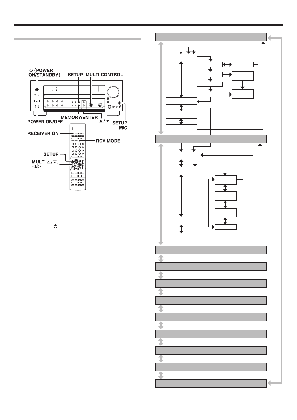
About the supplied remote control
Compared to standard remote controls, the remote control supplied with this model has several
operation modes. These modes enable the remote control unit to control other audio/video components.
In order to effectively use the remote control it is important to read the operating instructions and obtain
a proper understanding of the remote control and how to switch its operation modes (etc.).
Using the remote control without completely understanding its design and how to switch the operation
modes may result in incorrect operations.
B60-5561-10 01 CS (E,X) OC 0504
Page 2
Before applying the power
Caution : Read this page carefully to ensure safe
operation.
Units are designed for operation as follows.
U.S.A. and Canada ........................................... AC 120 V only
Australia ........................................................... AC 240 V only
Europe ............................................................... AC 230 V only
Other countries ............ AC 110-120 / 220-240 V switchable
Information on Disposal of Old Electrical and
Electronic Equipment (applicable for EU countries
that have adopted separate waste collection
systems)
Products with the symbol (crossed-out wheeled
bin)cannot be disposed as household waste.
Old electrical and electronic equipment should
be recycled at a facility capable of handling these
items and their waste byproducts.
Contact your local authority for details in locating a
recycle facility nearest to you.
Proper recycling and waste disposal will help conserve
resources whilst preventing detrimental effects on our
health and the environment.
Safety precautions
WARNING :
TO PREVENT FIRE OR ELECTRIC SHOCK,
DO NOT EXPOSE THIS APPLIANCE TO
RAIN OR MOISTURE.
How to use this manual
This manual is divided into four sections, Preparations, Operations,
Remote Control, and Additional Information.
Preparations
Shows you how to connect your audio and video components to this
model and prepare the surround processor.
Since this model works with all your audio and video components, kindly
follow the instructions in this manual for the correct connections.
Operations
Shows you how to operate the various functions available on this model.
Remote Control
Shows you how to operate other components using the remote control,
as well as a detailed explanation of all remote control operations. Once
you have registered your components with the proper setup codes, you’ll
be able to operate both this receiver and your other AV components (TV,
VCR, DVD player, CD player, etc.) using the remote control supplied with
this receiver.
Additional Information
Shows you additional information such as “In case of difficulty”
(troubleshooting) and “Specifications”.
Maintenance of the unit
When the front panel or case becomes dirty, wipe with a soft, dry
cloth. Do not use thinner, benzine, alcohol, etc. for these agents may
cause discoloration.
In regard to contact cleaner
Do not use contact cleaners because it could cause a malfunction. Be
specially careful not to use contact cleaners containing oil, for they
may deform the plastic component.
CAUTION
RISK OF ELECTRIC SHOCK
DO NOT OPEN
CAUTION: TO REDUCE THE RISK OF ELECTRIC SHOCK, DO NOT
REMOVE COVER (OR BACK). NO USER-SERVICEABLE PARTS
INSIDE. REFER SERVICING TO QUALIFIED SERVICE PERSONNEL.
THE LIGHTNING FLASH WITH ARROWHEAD SYMBOL,
WITHIN AN EQUILATERAL TRIANGLE, IS INTENDED TO
ALERT THE USER TO THE PRESENCE OF UNINSULATED
“DANGEROUS VOLTAGE” WITHIN THE PRODUCT’S
ENCLOSURE THAT MAY BE OF SUFFICIENT MAGNITUDE
TO CONSTITUTE A RISK OF ELECTRIC SHOCK TO
PERSONS.
THE EXCLAMATION POINT WITHIN AN EQUILATERAL
TRIANGLE IS INTENDED TO ALERT THE USER TO THE
PRESENCE OF IMPORTANT OPERATING AND
MAINTENANCE (SERVICING) INSTRUCTIONS IN THE
LITERATURE ACCOMPANYING THE APPLIANCE.
EN
2
Page 3
Before applying the power
Contents
Caution : Read the pages marked carefully to ensure
safe operation.
Before applying the power ...................................................... 2
Safety precautions ..................................................................... 2
How to use this manual .............................................................2
Unpacking .................................................................................. 4
Preparing the remote control ..................................................... 4
Special features ......................................................................... 5
Names and functions of parts ................................................. 6
Main Unit .................................................................................... 6
Remote control unit ................................................................... 7
Setting up the system ........................................ 8
Connecting the terminals .................................. 9
Connecting a DVD player (6-channel input) ..... 10
Connecting audio components ........................ 11
Connecting video components ........................ 12
Digital connections .......................................... 13
Connecting video components
(COMPONENT VIDEO) .................................... 14
Preparations
Connecting the speakers .................................15
PRE OUT connections ..................................... 16
Connecting to another room (ROOM B) ......... 17
Connecting to the AV AUX jacks ..................... 18
Connecting the antennas ................................. 18
Preparing for surround sound ....................... 19
Before setting up the speakers ....................... 19
Setting up the speakers automatically (AUTO SETUP)
“Kenwood Room Acoustic Calibration” ............ 20
Setting up the speakers manually
(MANUAL SETUP) ........................................... 22
Other settings .................................................. 24
Remote
Control
Additional
Information
Basic remote control operations for other
components ....................................................... 43
Registering setup codes for other components
......................................................................... 43
Searching for your codes ................................. 43
Checking the codes ......................................... 43
Re-assigning device keys ................................ 44
Operating other components .......................... 44
Storing the remote control code of the other
components ..................................................... 45
Setup code chart .............................................. 46
Other components’ operations ....................... 58
In case of difficulty .......................................... 62
Specifications .................................................. 64
Operations
Normal playback.............................................. 26
Preparing for playback ..................................... 26
Listening to a source component .................... 26
Input level adjustment (analog sources only) .. 27
Adjusting the sound ......................................... 27
Recording .......................................................... 29
Recording audio (analog sources) ................... 29
Recording audio (digital sources) .................... 29
Recording video ............................................... 29
Listening to radio broadcasts ....................... 30
Tuning (non-RDS) radio stations ...................... 30
Using RDS (Radio Data System) ..................... 30
Presetting radio stations manually .................. 31
Receiving preset stations ................................ 31
Receiving preset stations in order (P.CALL) ... 31
Using the RDS DISP (Display) key .................. 32
Presetting RDS stations
(RDS AUTO MEMORY) .................................. 32
Tuning by Program TYpe (PTY search) ............ 33
Ambience effects ............................................. 34
Surround modes .............................................. 34
Surround play ................................................... 37
Virtual modes ................................................... 39
DVD 6-channel playback .................................. 39
Adjusting the sound ......................................... 40
Convenient functions ...................................... 42
Display dimmer adjustment ............................ 42
Sleep timer ....................................................... 42
EN
3
Page 4
Before applying the power
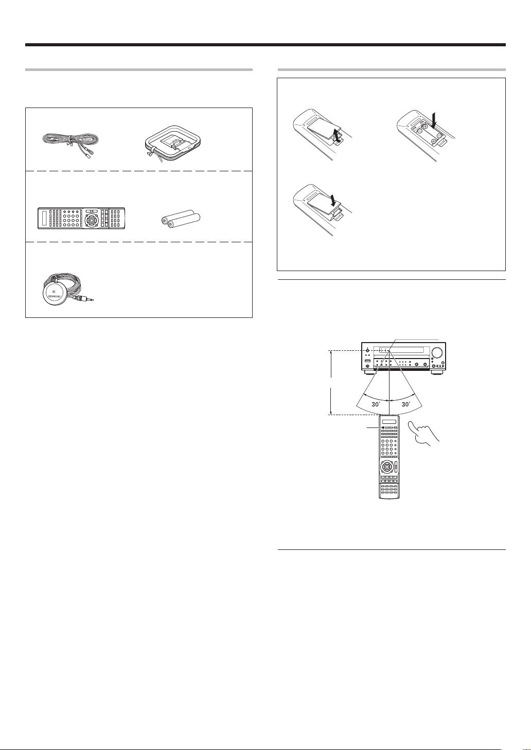
Unpacking
Unpack the unit carefully and make sure that all accessories are
present.
FM indoor antenna (1) AM loop antenna (1)
Remote control unit (1) Batteries (R03/AAA) (2)
RC-R0918E
Microphone for SETUP (1)
(Cord length: approx. 5m)
If any accessories are missing, or if the unit is damaged or fails to operate,
notify your dealer immediately. If the unit was shipped to you directly,
notify your shipper immediately. Kenwood recommends that you retain
the original carton and packing materials in case you need to move or ship
the unit in the future.
Keep this manual handy for future reference.
Preparing the remote control
Loading the batteries
1 Remove the cover. 2 Insert the batteries.
3 Close the cover.
• Insert two AAA-size (R03) batteries as indicated by the polarity
markings.
Operation
When the standby indicator is lit, the power turns ON when you press the
RECEIVER ON key on the remote control. When the power comes ON,
press the key you want to operate.
Operating range
(Approx.)
6 m
Remote sensor
RECEIVER ON
Infrared ray system
• When pressing more than one remote control key successively, press
the keys securely by leaving an interval of 1 second or more between
keys.
Notes
1. The supplied batteries may have shorter lives than ordinary batteries
due to use during operation checks.
2. When the remote-controllable distance gets shorter than before,
replace both batteries with new ones.
3. Placing the remote sensor in direct sunlight, or in direct light from a
high frequency fluorescent lamp may cause a malfunction.
In such a case, change the location of the system installation to
prevent malfunction.
EN
4
Page 5

Before applying the power
Special features
True home theater sound
This model incorporates a wide variety of surround modes to bring you
maximum enjoyment from your video software. Select a surround mode
according to your equipment or the software you are going to play and
enjoy!
• THX Select2 Cinema
• THX MusicMode
• THX Games
• THX Surround EX
• Dolby Digital EX
• Dolby Pro Logic IIx
• Dolby Digital
• Dolby Virtual Speaker
• Dolby Headphone
• DTS-ES
• DTS Neo:6
• DTS 96/24
• DTS
• DSP Mode
›
Kenwood Room Acoustic Calibration
Without going through a complicated manual setup procedure, this
function automatically measures the capacity of your speaker system,
speaker layout and acoustic specifications of your listening room correctly
with the provided microphone, and provides the best listening
environment.
ACTIVE EQ
ACTIVE EQ mode will produce a more dynamic sound quality in any
condition. You can enjoy a more impressive sound effect when ACTIVE
EQ is turned on.
GAME mode function
When you connect a game machine to the AV AUX jacks on the front
panel, the input selector of the receiver switches automatically to
"GAME" and the optimum sound field for enjoying games is set.
This feature improves your convenience in playing video games.
)
¶
§
Universal IR (InfraRed) remote control
In addition to the basic receiver operations, the remote control unit
supplied with this receiver can also operate almost all of your remote
controllable audio and video components. Just follow the simple setup
procedure to register the components you have connected.
Video up conversion
This receiver can convert the incoming composite video signals to SVideo signal.
If your monitor TV has S-Video jacks, it is not necessary to do the
composite video connections, just use an S-Video cord to connect the
receiver and your monitor TV.
RDS (Radio Data System) tuner
This model is equipped with an RDS tuner that provides several convenient
tuning functions: RDS Auto Memory, to automatically preset up to 40
RDS stations broadcasting different programs; station name display, to
show you the name of the current broadcast station; and PTY search to
let you tune stations by program type.
PTY (Program TYpe) search
Tune the stations by specifying the type of program you want to hear.
EN
5
Page 6
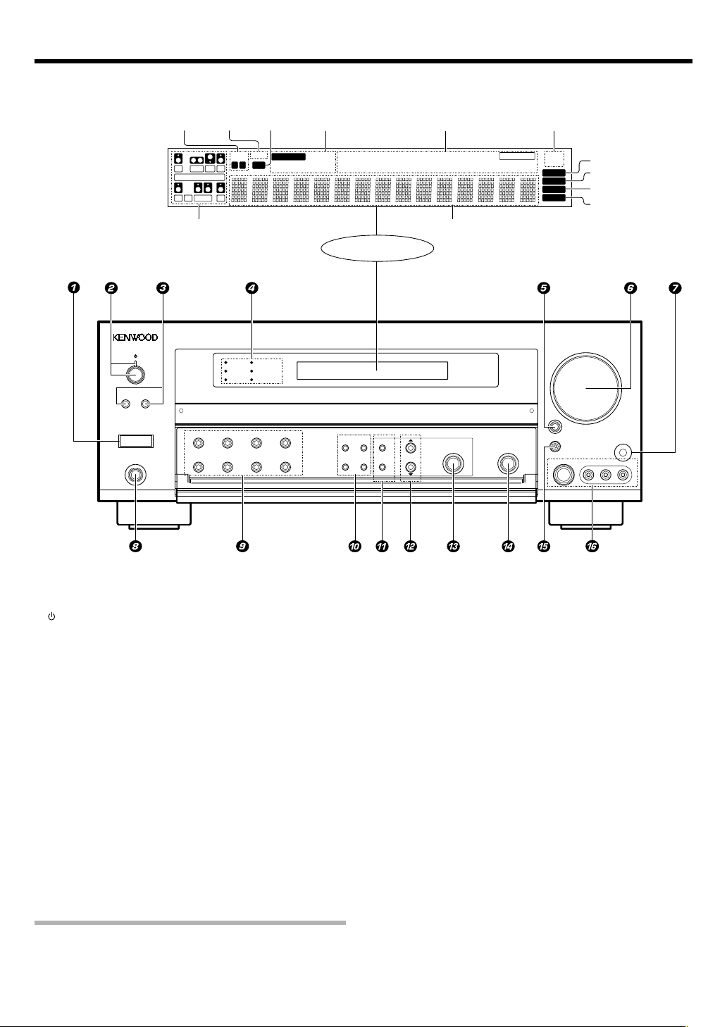
Names and functions of parts
Main unit
*Input channel
indicators
Input channel indicators
light up according to the
incoming audio signals.
"S" indicator will light up
when the surround component of the audio signals is only 1 channel.
Speaker
indicators
*Input channel indicators
Output channel indicators
MUTE
indicator
SW
L
CR
LFE
SL S SB SR
SP
AB
MUTE
CLIP
CLIP
indicator
AUTO DETECT
Input mode
indicators
DIGITAL DOLBY DIGITAL EX
6CH INPUT
The figure is the view when the front cover is open.
DOLBY DIGITAL
THX
DTS
96kHz fs
DSP
ACTIVE EQ
A SPEAKERS B
POWER
-ON –
PHONES
OFF
THX DOLBY VIRTUAL STEREO INPUT MODE
BASS BOOST DSP ACTIVE EQ DIMMER
DOLBY EX
DOLBY PL II x
Display
SOUND TONE SETUP
AUTO
MEMORY
/MONO
BAND
/ENTER
Listen mode indicators
SLEEP indicator
DOLBY H
DTS 96/24
DOLBY VS
ES MATRIX6.1
ES DISCRETE6.1
MULTI CONTROL
RDS indicators
NEO:6
STEREO
96kHzfs
LOUDNESS
Frequency display
Input display
Preset channel display
Surround mode display
SLEEP
Surround EX
DSP MODE
LISTEN MODE
THX
RDS
PTY
AUTO
MEMORY
STEREO
TUNED
S VIDEO
AUTO indicator
MEMORY indicator
STEREO indicator
TUNED indicator
VOLUME CONTROL
INPUT
SELECTOR
AV AUX/GAME
VIDEO L-AUDIO-R
SETUP MIC
1 POWER ON/OFF key (
Use to turn the main power on or off.
(POWER ON/STANDBY) key (
2
Use to turn the power ON/STANDBY when
the Power is turned ON.
Standby indicator
3 SPEAKERS A/B keys §
Use to turn the A/B speakers on or off.
4 THX indicator ‡
Lights when the THX mode has been chosen.
96kHz fs indicator q
Lights when the receiver is in the 96kHz
LPCM playback mode.
ACTIVE EQ indicator ¶
Lights when the ACTIVE EQ is ON.
DOLBY DIGITAL indicator ‡
Lights when the receiver is in the Dolby
Digital mode.
DTS indicator ‡
Lights when the receiver is in the DTS mode.
DSP indicator °
7 SETUP MIC jack (
Use for SETUP MIC.
8 PHONES jack •
Use for headphone listening.
9 THX key ‡
Use to switch the status of THX.
DOLBY VIRTUAL key ·
Use to select the Dolby Virtual Speaker and
the Dolby Headphone setting.
STEREO key °
Use to switch the listen mode to STEREO.
INPUT MODE key 8
Use to select the Input mode.
BASS BOOST key •
Use to select BASS BOOST setting.
DSP key °
Use to select any of the DSP mode.
ACTIVE EQ key ¶
Use to select ACTIVE EQ setting.
DIMMER key
Use to adjust the brightness of the display.
Lights when the receiver is in the DSP mode.
5 INPUT SELECTOR key §
Use to select input sources.
6 VOLUME CONTROL knob §
Use to select the REC MODE. ª
0 SOUND key ‚
Use to adjust the sound quality and the
ambience effects.
Standby mode
While the standby indicator is lit, a small amount of power is supplied to
the system to back up the memory. This is called standby mode.
Under the condition, the system can be turned ON by remote control unit.
EN
6
TONE key •
Use to switch the status of TONE control.
BAND key º
Use to select the broadcast band.
AUTO/MONO key º
Use to select the auto or manual tuning
mode.
! SETUP key (
Use to select the speakers' settings etc.
MEMORY/ENTER key
Use to store radio stations in the preset
memory. ⁄
Use to establish a selection.
@ 5/∞ keys (‚
Use for selection adjustments during sound
and setup functions.
# MULTI CONTROL knob
Use to control a variety of settings.
$ LISTEN MODE knob ‡
Use to select the listening mode.
% AV AUX/GAME key *§
w
Use to switch the input to AV AUX or GAME.
^ AV AUX (S VIDEO, VIDEO, L-AUDIO-R)
jacks *
Page 7
Names and functions of parts
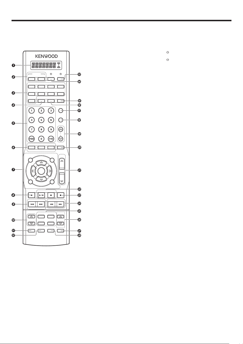
Remote control unit
This remote control unit can be used not only for Kenwood products but also for other non-Kenwood products by setting the appropriate manufacturer’s
setup codes. e
RECEIVER
ON
DVD/6CH
CD/DVD
TUNER
INFO
TONE
AUDIO
TOP MENU
/SETUP
RETURN
/EXIT
DIMMER
P.CALL TUNING
–
CHANNEL
LISTEN MODE
INPUT MODE
TV
SOURCE
STANDBY
VIDEO3
VIDEO2VIDEO1
PHONOMD/TAPE
AV AUX
RCV MODEACTIVE EQ
TV MODE
TV INPUT
TV MUTE
TV VOL.
BASS BOOST
LOUDNESS
MUTE
ANGLE
SUBTITLE
MENU
VOLUME
/SOUND
MULTI
ENTER
MULTI
ON SCREEN
/GUIDE
BAND
AUTO/MONO SLEEP
+
DOLBY VIRTUAL
DSP MODE RDS DISP.
PAGE
THXSTEREO
DISC SKIP
PTY
LEARNLASTINPUT SEL.
DISC SEL.
1 LCD (Liquid Crystal Display) e
Shows the operation mode of the remote
control unit.
2 RECEIVER ON key (
Use to turn the receiver on.
RECEIVER STANDBY key
Use to turn the receiver off (standby).
Input Selector keys (DVD/6CH, VIDEO 1,
3
VIDEO 2, VIDEO 3, CD/DVD, MD/TAPE, PHONO,
AV AUX, TUNER)
Used to select the input sources.
Source keys (DVD/6CH,
VIDEO 3,
AUX,
Use to select registered components.
4 ACTIVE EQ key ¶
Use to select ACTIVE EQ setting.
5 Numeric keys
Use to input numeric characters. e
Use to select preset radio stations. ⁄
Use to operate other components.
6 TONE key •
Use to switch the status of TONE control.
BASS BOOST key •
Use to select the maximum adjustment
setting for the low frequency range.
LOUDNESS key •
Use to switch the status of LOUDNESS.
AUDIO key
SUBTITLE key
ANGLE key
Use to operate other components.
7 MULTI %/fi/@/# keys
Use to control a variety of settings.
Use to operate other components.
TOP MENU key
MENU key
RETURN key
EXIT key
ON SCREEN key
GUIDE key
Use to operate other components.
ENTER key
Use to establish a selection.
Use to operate other components.
SETUP key (
Use to select the speakers’ settings etc.
SOUND key ‚
Use to adjust the sound quality and the
ambience effects.
8 DIMMER key w
Use to adjust the brightness of the display.
8 key
Use to operate other components.
9 P.CALL 4/¢ keys ⁄
Use for selection adjustments during sound,
set up and preset channel functions.
CHANNEL –/+ keys
Use to select the channels.
0 LISTEN MODE %/fi keys ‡
Use to select the listening mode.
! INPUT MODE key 8
Use to select the Input mode.
@ DISC SEL. key
INPUT SEL. key
Use to operate other components.
CD/DVD, MD/TAPE, PHONO, AV
TUNER
) et
VIDEO 1, VIDEO 2,
§
TV key
#
Use to turn the TV on or off.
$
SOURCE key
Use to turn the other source components on
or off.
% TV MODE key
Use to select the TV equipment.
^ RCV MODE key
Use to switch the remote control unit to the
receiver control mode.
& TV INPUT key
Use to select TV’s input.
* TV MUTE key
Use to temporarily mute the TV sound.
( TV VOL. %/fi keys
Use to adjust the TV’s volume.
) MUTE key •
Use to temporarily mute the sound.
¡ VOLUME %/fi keys §
Use to adjust the receiver’s volume.
™ BAND key º
Use to select the broadcast band.
3/8 key
Use to operate the DVD, CD, MD or VCR
component.
AUTO/MONO key º
Use to select the auto or manual tuning
mode.
7 key
Use to operate the DVD, CD, MD or VCR
component.
£ SLEEP key w
Use to set the Sleep timer.
÷ key
Use to operate the MD or VCR components.
¢ TUNING 1/¡ keys º
Use to tune the broadcast station.
∞ DSP MODE key °
Use to select any of the DSP mode.
DOLBY VIRTUAL key ·
Use to select the Dolby Virtual Speaker and
the Dolby Headphone setting.
STEREO key °
Use to switch the listen mode to STEREO.
THX key ‡
Use to switch the status of THX.
§ PAGE %/fi keys
Use to operate other components.
RDS DISP. key ¤
Use to receive RDS broadcast.
PTY key ‹
Use for PTY search.
¶ LEARN key
Use to register other components. e
Use to memorize the operation of the other
remote code. t
• DISC SKIP key
LAST key
Use to operate other components.
EN
7
Page 8
Setting up the system
Make connections as shown in the following pages.
When connecting the related system components, be sure
to refer to the instruction manuals supplied with the
components you are connecting.
Do not connect the power cord to a wall outlet until all
connections are completed.
Notes
Be sure to insert all connection cords securely. If their connections are
1.
imperfect, sound may not be produced or there will be noise inference.
2. Be sure to remove the power cord from the AC outlet before plugging
or unplugging any connection cords. Plugging/unplugging connection
cords without disconnecting the power cord can cause malfunctions
and may damage the unit.
CAUTION
Do not connect power cords from components whose power
consumption is larger than what is indicated on the AC outlet at the
rear of this unit.
Analog connections
Audio connections are made using RCA pin cords. These cables transfer
stereo audio signal in an “analog” form. This means the audio signal
corresponds to the actual audio of two channels. These cables usually
have 2 plugs on each end, one red for the right channel and one white for
the left channel. These cables are usually packed together with the
source unit, or are available at your local electronics retailer.
Microcomputer malfunction
If operation is not possible or an erroneous display appears, even
though all connections have been made properly, reset the
microcomputer referring to “In case of difficulty”. „
Memory back up function
Please note that the following items will be deleted from the unit's
memory if the power cord is disconnected from the AC outlet for
approximately 1 day.
• Power mode
• Input selector settings
• Speaker ON/OFF
• Volume level
• BASS, TREBLE, INPUT level
• TONE ON/OFF
• LOUDNESS ON/OFF
• Dimmer level
• Listen mode setting
• Speaker settings
• Input mode setting
• Sound mode settings
• Broadcast band
• Frequency setting
• Preset stations
• Tuning mode
• ACTIVE EQ mode
• GAME mode setting
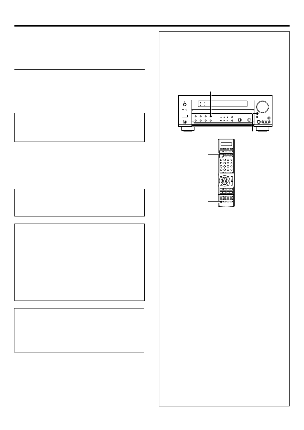
Input mode settings
CD/DVD, VIDEO 2, VIDEO 3 and DVD/6CH inputs each include jacks
for digital audio input and analog audio input.
The initial factory settings for audio signal playback for CD/DVD,
DVD/6CH and VIDEO 2 and VIDEO 3 are FULL AUTO.
After completing connections and turning on this model, follow the
steps below.
INPUT
MODE
INPUT
SELECTOR
Input Selector
keys
INPUT MODE
1 Use the INPUT SELECTOR key or Input Selector keys to select
CD/DVD, VIDEO 2, VIDEO 3 or DVD/6CH.
2 Press the INPUT MODE key.
Each press switches the setting as follows:
In DTS play mode
1 FULL AUTO (digital input, analog input)
2 DIGITAL MANUAL (digital input)
In CD/DVD, VIDEO 2, VIDEO 3 or DVD/6CH play mode
1 FULL AUTO (digital input, analog input)
2 DIGITAL MANUAL (digital input)
3 6CH INPUT (DVD/6CH input only)
4 ANALOG (analog input)
CAUTION
The power in this equipment will not be completely cut off from the wall
outlet when the power switch is turned off.
Install the equipment so that the wall outlet is easily accessible and, in
case of emergency, immediately unplug the power cord from the wall
outlet.
EN
8
Auto detect:
In FULL AUTO mode ("AUTO DETECT" indicator lights up), the
receiver detects the digital or analog input signals automatically.
The receiver will select the input mode and listening mode automatically during playback to match the type of input signal (Dolby
Digital, PCM, DTS) and the speaker setting. ‡
The "DIGITAL" indicator lights up when a digital signal is
detected. The "DIGITAL" indicator is extinguished when no
digital signal is detected.
Fixed to digital input:
Select this mode if you want to keep the decoding condition (Dolby
Digital, DTS, PCM, etc.) in the current listen mode.
When DIGITAL MANUAL mode is selected, the set listen modes
may be changed automatically depending on the input signal. ‡
Fixed to analog input:
Select this setting to play analog signals from a VCR, etc.
If the INPUT MODE key is pressed quickly, sound may not be
produced. Press the INPUT MODE key again.
Page 9
Setting up the system
Connecting the terminals
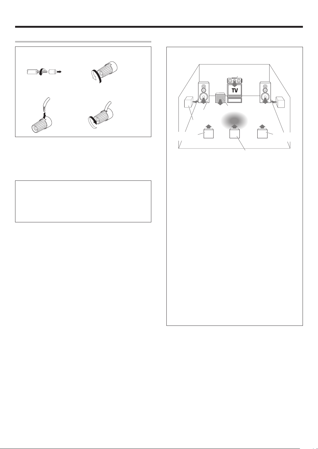
1 Strip coating. 2 Loosen.
3 Insert. 4 Secure.
• Never short circuit the + and – speaker cords.
• If the left and right speakers are connected inversely or the speaker
cords are connected with reversed polarity, the sound will be unnatural with ambiguous acoustic imaging. Be sure to connect the speakers
correctly.
Speaker impedance
After confirming the speaker impedance indications printed on the
rear panel of this model, connect speakers with matching
impedance ratings. Using speakers with a rated impedance other
than that indicated on the rear panel of this model could result in
malfunctions or damage to the speakers or this model.
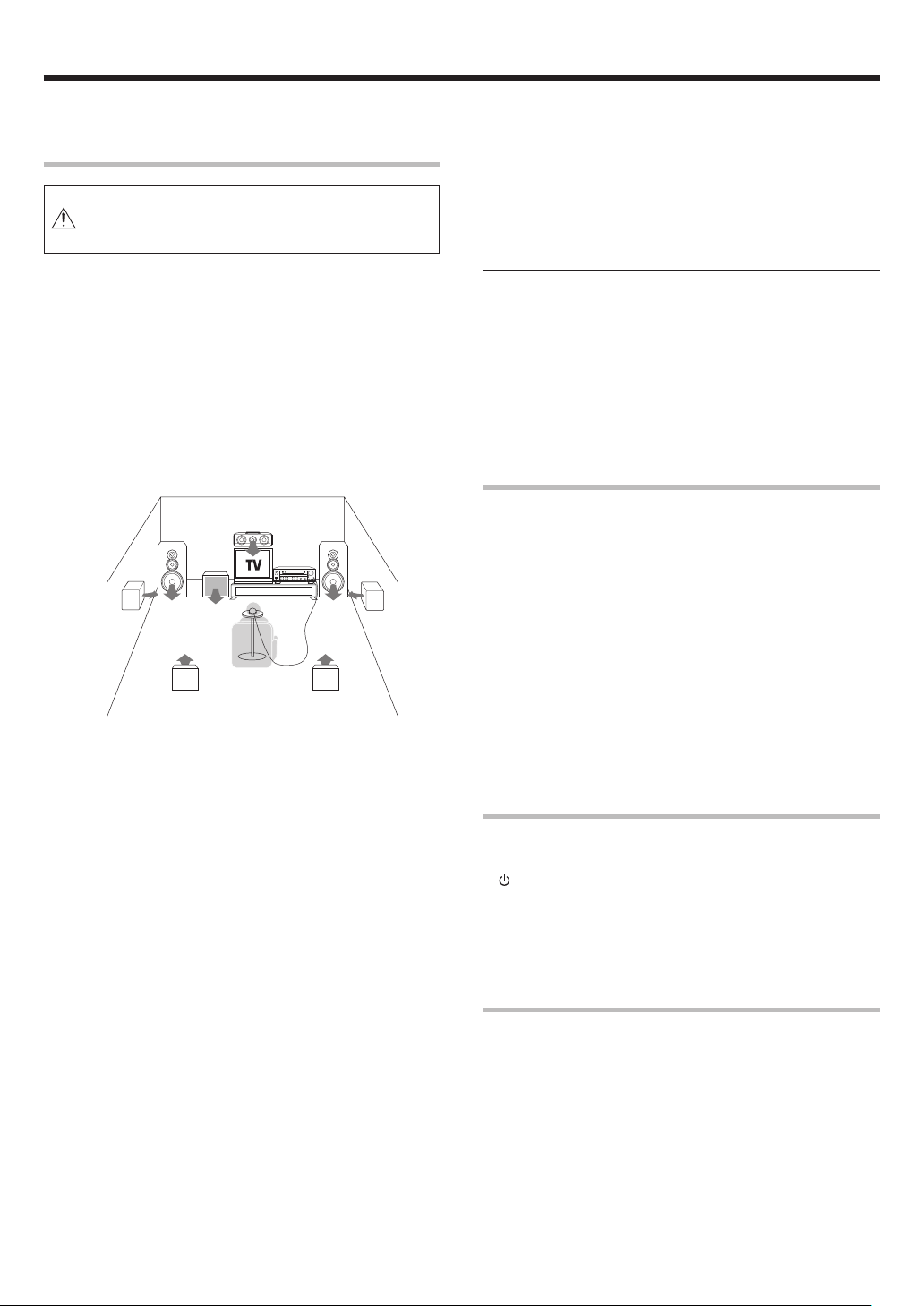
Speaker placement
Center Speaker
Front Speakers
(L, R)
Surround Speakers
(L, R)
*Surround Back
Left Speaker
For optimum results, place the Surround Back speakers together for
THX Select2 Cinema, THX MusicMode, and THX Games.
* For Surround Back Speaker, you may place either two Surround
Back Speakers (Surround Back Left Speaker and Surround Back
Right Speaker) for 7.1 channel surround sound system or one
Surround Back Speaker for 6.1 channel surround sound system.
Front (left and right) Speakers
Place at the front left and right of the listening position. Front speakers
are required for all surround modes.
Center Speaker
Place front and center. This speaker stabilizes the sound image and
helps recreate sound motion.
Surround (left and right) Speakers
Place at the direct left and right, or slightly behind, the listening
position at even heights, approximately 1 meter above the ears of the
listeners. These speakers recreate sound motion and atmosphere.
Subwoofer
Usually, place the subwoofer in the front center position in the
listening room, near one of the front speakers near the center
speaker. (Since the subwoofer has less directivity than other speakers, it can be placed almost in any position that can offer the best low
frequency reproduction according to the room layout.)
Surround Back Speaker/s
Place the surround back speaker behind the listening position, at the
same height as the left and right surround speakers.
• Although the ideal surround system consists of all the speakers
listed above, if you don't have a center speaker or a subwoofer, you
can divide those signals between the available speakers in the
speaker settings steps to obtain the best possible surround
reproduction from the speakers you have available. (
Subwoofer
Listening
position
*Surround Back
Right Speaker
(*Surround Back Speaker)
EN
9
Page 10
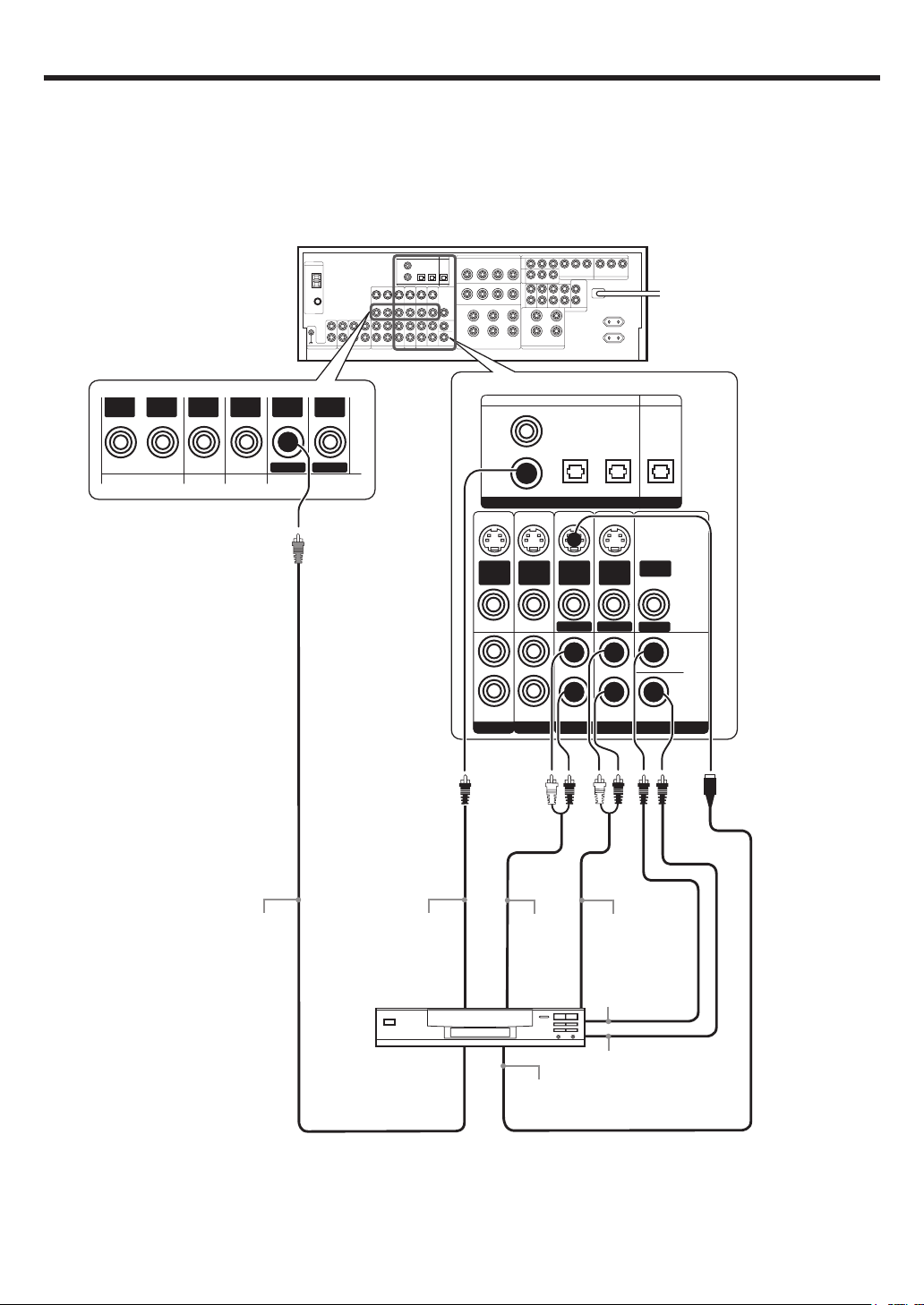
Setting up the system
Connecting a DVD player (6-channel input)
If you have connected a DVD player to this model with digital connection, be sure to read the “Input mode settings” section carefully. 8
OUT
VIDEOINVIDEO
For COMPONENT VIDEO
connection $
IN
VIDEO
IN
VIDEOINVIDEO
DVD
OUT
VIDEO
MONITOR
COAXIAL OPTICAL OPTICAL
VIDEO
2
DVD/
6CH
DIGITAL IN
S VIDEO
S VIDEO
IN
VIDEO
PLAY IN
S VIDEO
FRONT
IN
VIDEO
PLAY IN
VIDEO 2 VIDEO 3
IN
VIDEO
DVD
VIDEO 3
S VIDEO
OUT
VIDEO
MONITOR
SURROUND
DVD/6CH INPUT
OPTICAL
MONITORCD/DVD
DIGITAL OUT
VIDEO
OUT
ROOM B
CENTER
SUB
WOOFER
10
VIDEO OUT
COAXIAL
DIGITAL OUT
(AUDIO)
DVD Player
FRONT
OUT L/R
S VIDEO
OUT
SURROUND
OUT L/R
CENTER
OUT
SUBWOOFER
OUT
S VIDEO cord
EN
Page 11
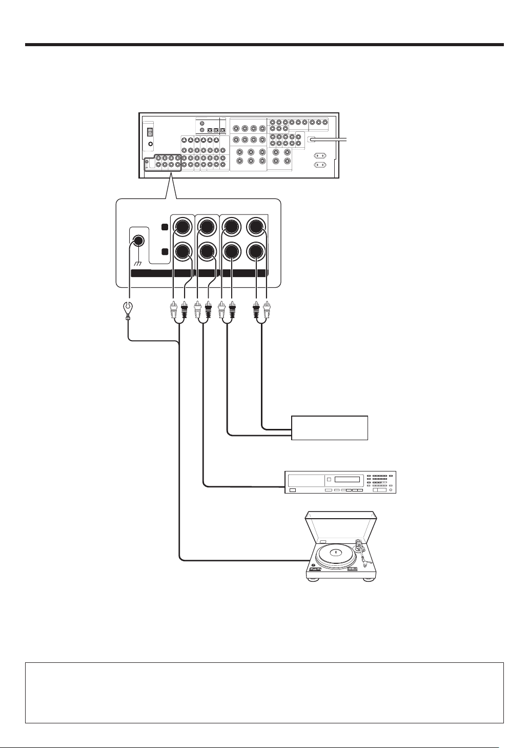
Setting up the system
Connecting audio components
L
To AC wall outlet
• The earth terminal with
the H symbol is used
for noise reduction of
record player. It is not
for safety earth.
RLR
PHONO
IN IN
CD/DVD
REC OUT PLAY IN
MD/TAPE
OUT
Cassette Deck or
MD Recorder
IN
OUT
DVD Player or CD Player
OUT
Record Player
with MM cartridge
Moving coil (MC) cartridge record
player cannot be used directly
from this model unit. It can only
be used when equalizer amplifier
for MC cartridge is connected.
CAUTION
Be sure to adhere to the following, or proper ventilation will be blocked causing damage or fire hazard.
• Do not place any object impairing heat radiation onto the top of the unit.
• Leave a space around the unit (from the largest outside dimension including projection) equal or greater than, shown below.
Top panel : 50 cm Side panel : 10 cm Back panel : 10 cm
11
EN
Page 12
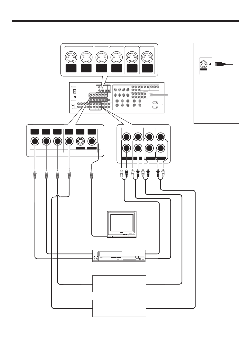
Setting up the system
Connecting video components
S VIDEO Jacks
About the S VIDEO
Jacks
* DVD IN input jack is used for
either CD/DVD input or DVD/
6CH input.
OUT
VIDEOINVIDEO
IN
VIDEO
S VIDEO
OUT
VIDEO
IN
VIDEOINVIDEO
DVD
S VIDEO
IN
VIDEO
MONITOR
OUT
VIDEO
S VIDEO
IN
VIDEO
S VIDEO
IN
VIDEO
S VIDEO
S VIDEO
OUT
IN
VIDEO
VIDEO 1 VIDEO 2 VIDEO 3
VIDEO
PLAY INPLAY INPLAY INREC OUT
S VIDEO
Use the S VIDEO Jacks to
make connections to
video components with
S VIDEO IN/OUT Jacks.
If you use the S VIDEO
•
jacks to connect your video
playback components, be
sure to use the S VIDEO
jacks when connecting
your monitor and video
recording components.
Monitor TV
Video
IN
Video Recorder
OUT
IN
Video
OUT
Video Audio
Video
DVD Player or LD Player
OUT
DVD Player or LD Player
IN
OUT
Audio
OUT
OUT
Audio
• A video component with digital audio outputs should be connected to the VIDEO 2 or VIDEO 3 jacks.
• For optimum video performance, THX recommends that video pass through (bypass) is used.
EN
12
Page 13
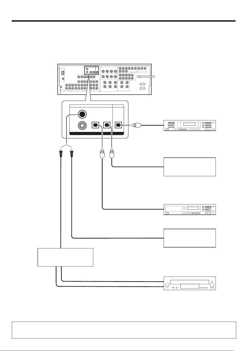
Setting up the system
Digital connections
The digital in jacks can accept DTS, Dolby Digital, or PCM signals. Connect components capable of outputting DTS, Dolby Digital, or standard PCM (CD)
format digital signals.
If you have connected any digital components to this model, be sure to read the “Input mode settings” section carefully. 8
VIDEO
2
DVD/
6CH
COAXIAL
DIGITAL
OUT
(AUDIO)
RF digital demodulator
(Commercially available)
COAXIAL OPTICAL OPTICAL
DIGITAL IN
VIDEO 3
Optical fiber cable
OPTICAL
MONITORCD/DVD
DIGITAL OUT
Optical
fiber cable
OPTICAL DIGITAL
IN (AUDIO)
Optical
fiber cable
OPTICAL DIGITAL
OUT (AUDIO)
OPTICAL DIGITAL
OUT (AUDIO)
COAXIAL DIGITAL
OUT (AUDIO)
MD Recorder
Component with DTS,
Dolby Digital, or PCM
OPTICAL DIGITAL OUT
Connect the video signal and
analog audio signals to the VIDEO
3 jacks.
(See “Connecting video components”.) @
DVD Player or CD Player
Component with DTS,
Dolby Digital, or PCM
COAXIAL DIGITAL OUT
Connect the video signal and
analog audio signals to the VIDEO
2 jacks.
(See “Connecting video components”.) @
DOLBY DIGITAL RF
OUT (AUDIO)
PCM OUT
LD Player
To connect an LD player with a DIGITAL RF OUT, connect the LD player to an RF digital demodulator (Commercially available).
Next, connect the DIGITAL OUT jack of the demodulator to the DIGITAL IN jack of this model.
Connect the video signal and analog audio signals to the VIDEO 2 or VIDEO 3 jacks. (See “Connecting video components”.)
13
EN
Page 14
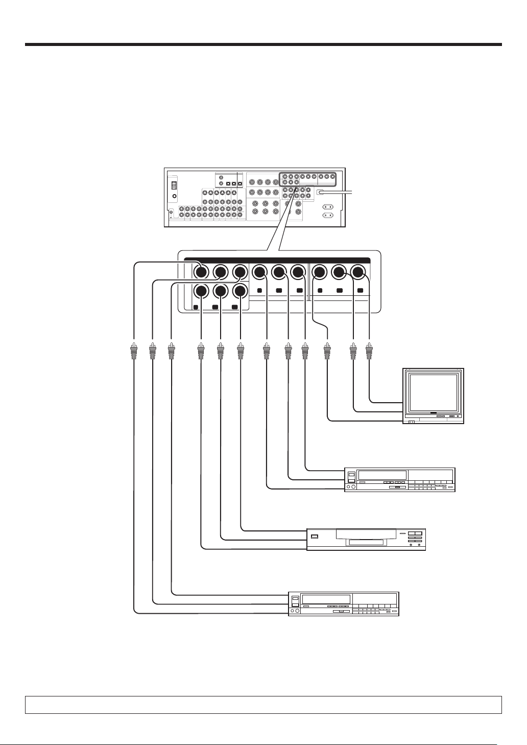
Setting up the system
Connecting video components (COMPONENT VIDEO)
If you have connected this model to a video component with COMPONENT jacks, you can get a better picture quality than by connecting to the S-VIDEO
jacks.
* DVD IN input jack is used for
either CD/DVD input or DVD/
6CH input.
VIDEO
3
IN
DVD
IN
COMPONENT VIDEO
C
R
C
B
Y
C
R
C
B
Y
VIDEO 2 IN
Y
MONITOR OUT
C
R
C
B
Monitor TV
(with component jacks)
CR IN
C
B
IN
Y IN
Video Recorder, DVD Recorder,
Satellite Cable Tuner & Game
Player (with component jacks)
CR OUT
C
B
OUT
Y OUT
C
C
DVD Player (with component jacks)
R
OUT
B
OUT
Y OUT
Video Recorder, DVD Recorder,
Satellite Cable Tuner & Game
Player (with component jacks)
C
R
OUT
B
OUT
C
Y OUT
When connecting the TV to the COMPONENT jacks, be sure to connect all the other components to the COMPONENT jacks.
EN
14
Page 15
Setting up the system
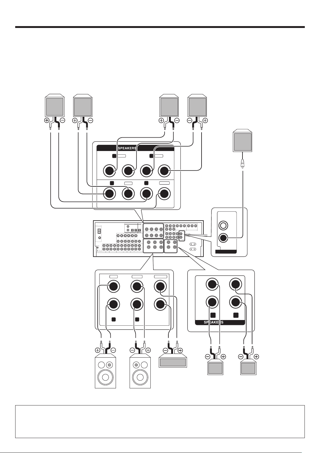
Connecting the speakers
Surround Back Speaker/s
When connecting a single
Surround Back Speaker,
connect it to SURROUND
BACK L terminals and select “SB LARGEx1” or “SB
NML/THXx1” at Speaker
settings. £
Left
Right
Surround Speakers
Right
Left
Powered
Subwoofer
SURROUND
SURROUND
BACK
+
-
R
+
R
+
RLCENTERFRONT A
GRAY
BLUE
-
TAN
-
L
-
+
BROWN
L
-
+
CENTER
SUB WOOFER
PRE OUT
GREENWHITERED
+
-
FRONT B
RL
Center
Speaker
Right
Left
Front Speakers B
Right
Left
Front Speakers A
• To make sure that each speaker has been connected properly, pay attention to the test tone from each speaker.
Refer to “2
Adjust the speaker volume level
.” £
• When you wish to connect the second pair of Front speakers or to connect the speakers in a different room to this unit, use the
SPEAKERS FRONT B terminals for connection.
15
EN
Page 16
Setting up the system
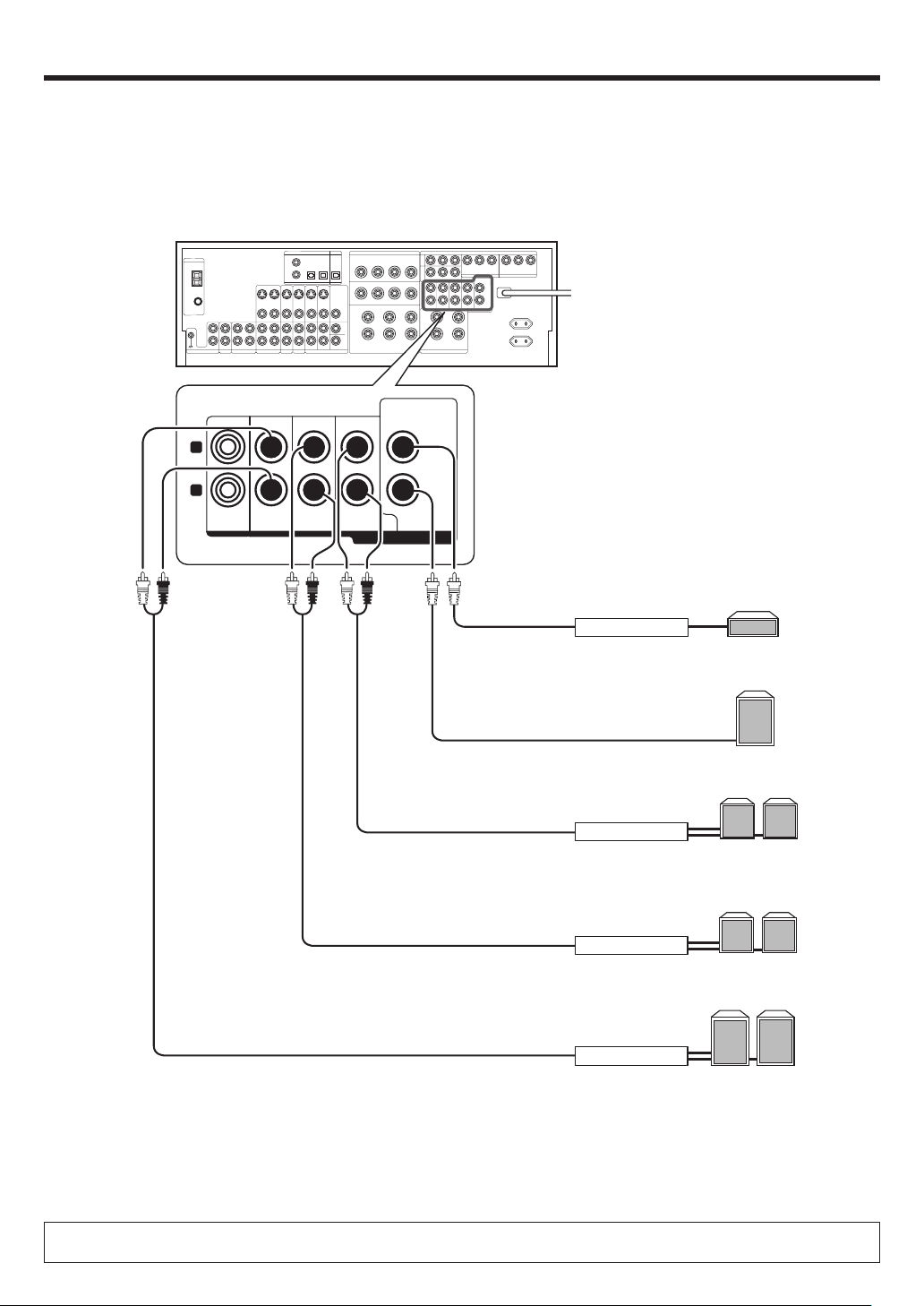
PRE OUT connections
This receiver has additional PRE OUT jacks. These can be used for various purposes, but will need to be connected to an external power amplifier as
shown in the example below.
CENTER
L
R
ROOM B FRONT
SURROUND SURROUND BACK
SUB WOOFER
PRE OUT
Power Amplifier
Power Amplifier
Power Amplifier
Center Speaker
Powered
Subwoofer
Surround Back
Speakers
R
L
Surround Speakers
LR
Front Speakers
Power Amplifier
• Connecting a speaker cord directly to a PRE OUT jack will not produce any sound from the speaker.
• To use the PRE OUT jacks, press only the SPEAKERS A key to the ON position. §
EN
16
R
L
Page 17
Setting up the system
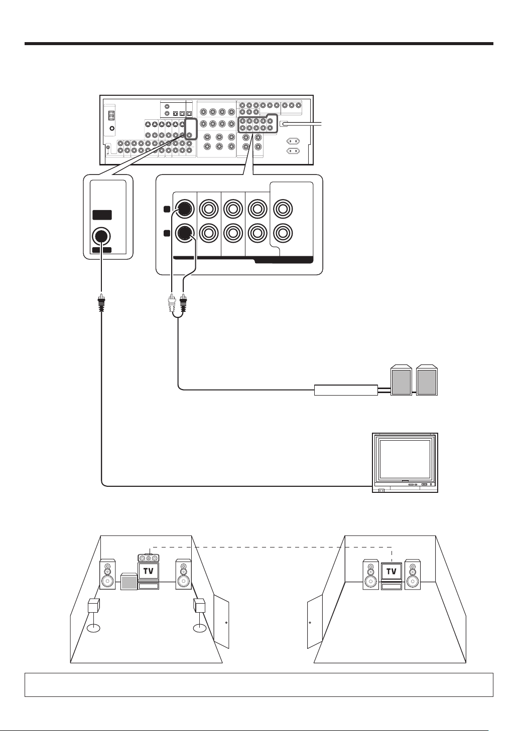
Connecting to another room (ROOM B)
This connection allows you to connect your main system to a monitor TV and speaker system located in another area (ROOM B).
CENTER
VIDEO
OUT
ROOM B
L
R
ROOM B FRONT
SURROUND SURROUND BACK
SUB WOOFER
PRE OUT
Power Amplifier
Front Speakers
(Room B)
Monitor TV (Room B)
ROOM A
(Main system)
The sound from ROOM B PRE OUT jacks is the same as that of the Front Speakers.
When listening in another room (ROOM B), set the LISTEN mode to STEREO. °
ROOM B
17
EN
Page 18
Setting up the system
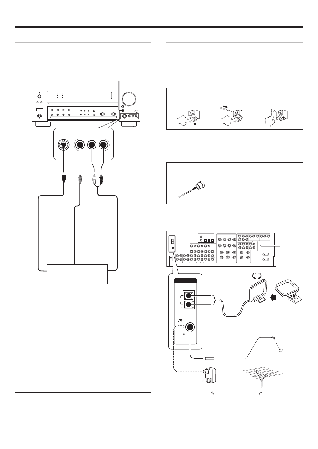
Connecting to the AV AUX jacks
The AV AUX jacks are convenient for connection of video components
such as a camcorder or a video game.
AV AUX/GAME
S VIDEO VIDEO L-AUDIO-R
S VIDEO cord
Connecting the antennas
The broadcast reception cannot be made unless the antennas are
connected. Connect the antennas correctly as instructed below.
AM Loop Antenna
Place the supplied loop antenna as far as possible from the receiver, TV
set, speaker cords and power cord, and adjust the direction for best
reception.
AM Antenna Terminal connections
1 Push lever. 2 Insert cord. 3 Release lever.
FM Indoor Antenna
The supplied indoor antenna is for temporary use only. For stable signal
reception we recommend using an outdoor antenna. Disconnect the
indoor antenna when you connect one outdoors.
FM Antenna Terminal connections
Insert cord.
FM Outdoor Antenna
Lead the 75Ω coaxial cable connected to the FM outdoor antenna into the
room and connect it to the 75Ω FM terminal.
VIDEO OUT
Video game, Camcorder,
S VIDEO OUT
• This model has a game function which is convenient for using
game equipment.
It is recommended that the game equipment be connected to
AV AUX jacks and the game mode be turned ON. §
• To select the source connected to the AV AUX jacks press AV
AUX/GAME key. §
• When you connect the audio source such as the MD player, you
do not need to connect the video cable.
• When you connect the component with the S VIDEO cord, you
can get better picture quality.
EN
18
other VCR or Portable
MD Player
AUDIO OUT
ANTENNA
AM
GND
75
FM
Use an antenna
adaptor
(Commercially
available)
Attach to the stand
AM Loop Antenna
FM Indoor Antenna
FM Outdoor Antenna
Page 19
Preparing for surround sound
Before setting up the speakers
For the optimum surround playback, variety of speaker settings are
necessary.
Following the procedure below, go through the settings described in
further pages.
When performing "Setting up the speakers automatically
1
(AUTO SETUP)", connect the provided microphone for setup
to the SETUP MIC jack.
Turn on the power to this receiver by pressing the POWER
2
ON/OFF key and
ON key.
If you want to use the remote control unit, press the RCV
3
MODE key on the remote control unit to set it to the receiver
control mode.
(POWER ON/STANDBY) key, or RECEIVER
AUTO SETUP
CALIBRATE
Measuring
Analyzing
COMPLETE
CONFIRM
TEST SIG LVL
RETURN
MANUAL SETUP
SP SETUP
SP LEVEL
SP DISTANCE
RETURN
SW RE-MIX
START
T. TO NE
AUTO
T. TO NE
MANUAL
T. TO NE
OFF
RETURN
RETURN
ERROR
MESSAGE
WARNING
MESSAGE
Press the SETUP key to enter the SETUP mode.
4
Use the
5/∞
keys or MULTI @/#keys for the following dis-
plays.
1 AUTO SETUP
2 MANUAL SETUP
3 SW RE-MIX
4 CROSSOVER
5 SB SPACING
6 BASS PEAK
7 LFE LEVEL
8 AUDIO DELAY
9 DISPLAY MODE
0 SETTING LOCK
- EXIT
The flow of the SETUP is as follows:
CROSSOVER
SB SPACING
BASS PEAK
LFE LEVEL
AUDIO DELAY
DISPLAY MODE
SETTING LOCK
EXIT
19
EN
Page 20
Preparing for surround sound
Setting up the speakers automatically
(AUTO SETUP)
“Kenwood Room Acoustic Calibration”
A very loud test sound is produced during the measurement. Please take into consideration that it may disturb
your neighborhood, especially, when you measure it at the
night time.
“Kenwood Room Acoustic Calibration” function automatically per-
forms the following adjustments with the provided microphone by
measuring sound characteristics for the best listening environment
according to your room conditions and speakers layout.
1 Speaker presence and its size
2 Volume level differences from each speaker
3 Sound delay from speakers
4 Room sound characteristics
• Image of the measurement
Place the microphone at a height of your ears.
Do not place any obstacles between the microphone and speakers
during the measurement.
The measurement may not be carried out properly because of
speaking voice or other noise. Keep it down while measuring.
Perform automatic calibration.
1
1 Use the 5/∞ keys or MULTI @/# keys to select the “AUTO
SETUP” and press the MEMORY/ENTER key or the ENTER key.
2 Use the 5/∞ keys or MULTI @/# keys to select the "CALI-
BRATE" and press the MEMORY/ENTER key or the ENTER key.
• The display which indicates start of the measurement, "START"
is displayed.
• If you wish not to start measuring, use the 5/∞ keys or MULTI
@/# keys to select "RETURN", and then press the MEMORY/
ENTER key or the ENTER key to return to "CALIBRATE"
display.
3 Press the MEMORY/ENTER key or the ENTER key to start
measuring.
• The display which indicates during the measurement, "Measuring..." is displayed.
• It takes about 2 minutes to complete the measurement.
• If the provided microphone is not connected, "E01:No MIC" is
displayed and no measurement is performed.
• After the measurement is completed, analyzing starts and
"Analyzing x/4" (x changes from 1 to 4) is displayed. When the
analyzing is completed, "COMPLETE" will be shown for a few
seconds, and changed to "CONFIRM".
• Do not turn off the receiver while measuring. Otherwise, the
measurement contents are changed back to the factory setting.
Exit the AUTO SETUP mode.
2
When "CONFIRM" is displayed, press the MEMORY/ENTER key
or the ENTER key.
• The display which indicates the confirmation of the measurement
contents, "SP SETUP" is displayed. ™
• Use the 5/∞ keys or MULTI @/# keys to select "RETURN" while
"CONFIRM" is displayed, and then press the MEMORY/ENTER
key or the ENTER key to return to the "AUTO SETUP" display.
Notes
• Sometimes due to the electrical complexities of subwoofers and the
interaction with the room, THX recommends setting the level and the
distance of the subwoofer manually.
• Sometimes due to interaction with the room, you may notice irregular
results when setting the level and/or distance of the main speakers.
If this happens, THX recommends setting them manually.
• Please note that any THX main speakers should be set to NML/THX
(80Hz).
If you set up your speakers using AUTO SETUP, please make sure
manually that any THX speakers are set to NML/THX with 80Hz
CROSSOVER.
Test signal level adjustment
If a message such as "Exx : No Spk XX" or "Wxx : No Spk XX" is displayed
even though each speaker is connected correctly, adjust the level of the
test signal.
1 While "CONFIRM" or "CALIBRATE" is displayed, use the 5/∞
keys or MULTI @/# keys to select "TEST SIG LVL", and then
press the MEMORY/ENTER key or the ENTER key.
2 Use the MULTI CONTROL knob or MULTI %/fi keys to select a
test signal level.
1 LEVEL LOW
2 LEVEL MID
3 LEVEL HIGH
3 Press the MEMORY/ENTER key or the ENTER key to accept the
setting.
4 Proceed to step 2 of "
Perform automatic calibration."
1
Cancelling the measurement
If you operate any of the keys shown below, the measurement is
cancelled and the display is return to the ordinary input display.
1
(POWER ON/STANDBY) key or RECEIVER STANDBY key
2 VOLUME CONTROL knob or VOLUME %/fi keys
3 SETUP key
4 INPUT SELECTOR key
• If the measurement is cancelled, the measurement contents are
changed back to the factory setting.
About error messages
If the receiver detects some kind of problems while in calibration, an error
message is shown in the display, and the processing is stopped.
Eliminate the problem according to the message and try the calibration
again. If there are more than one error messages, press the 5/∞ keys or
MULTI @/# keys to find the next one while the message is shown on the
display.
Press the MEMORY/ENTER key or the ENTER key to return to the
“CALIBRATE“ display.
20
EN
Page 21

Preparing for surround sound
E01 : No MIC
Microphone is not connected.
Connect the provided microphone for setup to the SETUP MIC
jack.
E02 : Headphone
Headphones are being connected.
Disconnect the headphones.
E03 : No Spk FL
E04 : No Spk FR
Front Left (Right) speaker is not connected.
Connect a Front Left (Right) speaker.
E05 : No Spk SL
E06 : No Spk SR
Surround Right (Left) speaker is detected, but Surround Left
(Right) speaker is not connected.
Connect a Surround Left (Right) speaker.
E99 : Error
Communication error occurred in the unit.
Try the calibration again. If the same message appears, consult
your dealer.
About the warning messages
Even if "COMPLETE" is shown on the display for several seconds and
the calibration is completed, a warning message may appears if some
kind of minor problems are detected.
Eliminate the problem according to the message and try the calibration
again, or understand the problem and finish up the AUTO SETUP.
• If there are more than one warning messages, press the 5/∞ keys or
MULTI @/# keys to find the next one while the message is shown on
the display.
• Pressing the MEMORY/ENTER key or the ENTER key changes back
the display to "CALIBRATE".
• Depending on the speakers, warning messages may appear even if the
speakers are connected correctly. In this case, it is not problems.
W01 : Phase F
The connection of either Front Left or Right speaker is not
correct (+ - inversion).
Make sure the + and - speaker cords are connected correctly for
Front Left and Right speakers.
E07 : No SpkSBL
Surround Back Right speaker is detected, but Surround Back Left
speaker is not connected.
For 7.1 channel system, connect a Surround Back Left speaker.
For 6.1 channel system, reconnect the Surround Back Right
speaker to SURROUND BACK L terminals.
E08 : SB w/o S
Surround Back speaker is detected, but Surround Left and Right
speakers are not connected.
Connect Surround Left and Right speakers.
E09 : MIC clip
Microphone detects a large volume signal.
Do not touch or shake the microphone, and try the calibration
again.
E10 : VolChange
Volume is changed while calibrating.
Do not change the volume while in calibration.
W02 : Phase S
The connection of either Surround Left or Right speaker is not
correct (+ - inversion).
Make sure the + and - speaker cords are connected correctly for
Surround Left and Right speakers.
W03 : Phase SB
The connection of either Surround Back Left or Right speaker is
not correct (+ - inversion).
Make sure the + and - speaker cords are connected correctly for
Surround Back Left and Right speakers.
W04 : No Spk C
Center speaker is not connected.
Connect a Center speaker if you have one.
If there is no Center speaker, no need to connect it.
W05 : No SW
Subwoofer is not connected.
Connect a Subwoofer if you have one.
If there is no Subwoofer, no need to connect it.
Continued to next page.
EN
21
Page 22

Preparing for surround sound
W06 : No Spk S
Surround speakers are not connected.
Connect a pair of Surround speakers if you have a set.
If there are no Surround speakers, no need to connect it.
W07 : No Spk SB
Surround Back speakers are not connected.
Connect a pair of Surround Back speakers if you have a set.
If there are no Surround Back speakers, no need to connect it.
W08 : No SpkSBR
Surround Back Right speaker is not connected.
Connect a Surround Back Right speaker if you have one.
If there is no Surround Back Right speaker, no need to connect it.
Setting up the speakers manually
(MANUAL SETUP)
Select a speaker system.
1
If you have THX certified speakers, please set them to NML/THX.
1 Press the 5/∞ keys or MULTI @/# keys to select the “MANUAL
SETUP” and press the MEMORY/ENTER key or the ENTER
key.
2 Select the “SP SETUP” and press the MEMORY/ENTER key
or the ENTER key again so that the subwoofer setting indication
“SUBW ON” appears.
SP MUTE
AB CLIP
L
CR
SW
LFE
SL SB SR
3 Use the MULTI CONTROL knob or MULTI %/fi keys to select
the appropriate subwoofer setting.
1 SUBW ON : A Subwoofer is connected to the receiver.
2 SUBW OFF : A Subwoofer is not connected to the receiver.
• The initial setting is “SUBW ON”.
• When Subwoofer output sound is required, select “FRNT NML/
THX”, or select both “FRNT LARGE” and “SW RE-MIX ON”.
4 Press the 5 key or MULTI # key to accept the setting.
• When the setting “SUBW ON” is selected, the front speakers
setting indication “FRNT” appears.
• When the setting “SUBW OFF” is selected, the Front Speakers
are automatically set to “FRNT LARGE” and the procedure skips
to step 7.
STEREO
L
CR
SW
LFE
SL SB SR
SP MUTE
AB CLIP
STEREO
5 Use the MULTI CONTROL knob or MULTI %/fi keys to select
the appropriate front speakers setting.
1 FRNT NML/THX : Average size Front Speakers are con-
nected to the receiver.
2 FRNT LARGE : Large size Front Speakers are connected
to the receiver.
6 Press the 5 key or MULTI # key to accept the setting.
• The Center Speaker setting indication “CNTR” appears.
7 Use the MULTI CONTROL knob or MULTI %/fi keys to select
the appropriate Center Speaker setting.
If you selected “FRNT LARGE” as the Front Speakers setting,
1 CNTR NML/THX : An average size Center Speaker is con-
nected to the receiver.
2 CNTR LARGE : A large size Center Speaker is connected
to the receiver.
3 CNTR OFF : A Center Speaker is not connected to the
receiver.
If you selected “FRNT NML/THX” as the Front Speakers
setting,
1 CNTR NML/THX : An average size Center Speaker is
connected to the receiver.
2 CNTR OFF : A Center Speaker is not connected to the
receiver.
8 Press the 5 key or MULTI # key again to accept the setting.
• The Surround Speaker setting indication “SURR” appears.
22
EN
Page 23

Preparing for surround sound
9 Use the MULTI CONTROL knob or MULTI %/fi keys to select
the appropriate Surround Speaker setting.
If you selected “FRNT LARGE” as the Front Speaker setting,
1 SURR NML/THX : Average size Surround Speakers are con-
nected to the receiver.
2 SURR LARGE : Large size Surround Speakers are
connected to the receiver.
3 SURR OFF : Surround Speakers are not connected to
the receiver.
If you selected “FRNT NML/THX” as the Front Speaker setting,
1 SURR NML/THX : Average size Surround speakers are
connected to the receiver.
2 SURR OFF : Surround Speakers are not connected to
the receiver.
0 Press the 5 key or MULTI # key again to accept the setting.
• When the setting other than “SURR OFF” is selected, the
Surround Back Speaker setting indication “SB” appears.
• When the setting “SURR OFF” is selected, the procedure skips
to step @.
! Use the MULTI CONTROL knob or MULTI %/fi keys to select
appropriate Surround Back Speaker setting.
If you selected “SURR LARGE” as the Surround Speaker
setting,
1 SB NML/THXx1 : A single average size Surround Back
Speaker is connected to the receiver.
2 SB NML/THXx2 : A pair of average size Surround Back Speak-
ers are connected to the receiver.
3 SB LARGEx1 : A single large size Surround Back Speaker
is connected to the receiver.
4 SB LARGEx2 : A pair of large size Surround Back Speak-
ers are connected to the receiver.
5 SB OFF : Surround Back Speakers are not connected
to the receiver.
L
CR
SW
LFE
SL SB SR
SP MUTE
AB CLIP
STEREO
If you selected “SURR NML/THX” as the Surround Speaker
setting,
1 SB NML/THXx1 : A single average size Surround Back
Speaker is connected to the receiver.
2 SB NML/THXx2 : A pair of average size Surround Back Speak-
ers are connected to the receiver.
3 SB OFF : Surround Back Speakers are not connected
to the receiver.
@ Press the MEMORY/ENTER key or the ENTER key to return to
the “SP SETUP” display.
Adjust the speaker volume level.
2
If you have a commercially available sound pressure meter, set the
meter readout to "C" at the listening position and adjust the sound
volume of each channel so that the noise level will reach 75dB. If you
do not have a sound pressure meter, start the volume level from 0db
and adjust so that the level from each speaker is almost the same.
• Indicators appear only for the channels of the speakers selected
in step 1.
Be aware that the TEST TONE is quite a lod sound (0dB).
1 Press the 5/∞ keys or MULTI @/# keys to select the “SP LEVEL“
and press the MEMORY/ENTER key or the ENTER key.
2 Press the 5/∞ keys or MULTI @/# keys for the following
displays:
1 T.TONE AUTO : Adjust the volume level from each
speaker by using test tone.
Test tone will be output from each
speaker in order.
2 T.TONE MANUAL : Adjust the volume level from each speaker
by using test tone.
3 T.TONE OFF : Adjust the volume level from each
speaker without using test tone.
4 RETURN : Press the MEMORY/ENTER key or the
ENTER key to return to the “SP LEVEL“
display.
3 After selecting “T.TONE AUTO” or “T.TONE MANUAL”,
press the MEMORY/ENTER key or the ENTER key to begin
TEST TONE.
Use the MULTI CONTROL knob or MULTI %/fi keys to adjust
the volume level of the test tone output from the speaker
channel to be adjusted.
For T.TONE AUTO selection, the test tone is heard from the
speakers in the following sequence for 2 seconds each starting from the Front Left speaker.
LEFT CNTR RIGHT
SL
SBLSUBW
SBR
• If you have selected “SB NML/THXx1” or ”SB LARGEx1”,
“SBR” and “SBL” are not appeared but “SB” is appeared on the
Display.
The channel indication blinks while the test tone is being output.
SP MUTE
AB CLIP
L
CR
SW
LFE
SL SB SR
• If the speaker setting selects are OFF, the speaker level settings
are reset.
For “T.TONE MANUAL” selection, press the 5/∞ keys or
MULTI @/# keys each time to select the speaker channel.
If “T.TONE OFF” is selected, test tone is not output. Adjust
the volume level from each speaker by listening the selected
input source. §
4 Press the MEMORY/ENTER key or the ENTER key to return to
the “SP LEVEL“ display.
• The test tone is turned off and return to the main setup displays.
Input the distance to the speakers.
3
• Indicators appear only for the channels of the speakers selected
in step 1.
1 Press the 5/∞ keys
or MULTI
@/# keys to select the “SP
DISTANCE“ and press the MEMORY/ENTER key or the ENTER key.
2 Use the 5/∞ keys or MULTI @/ # keys to select a unit in
distance and press the MEMORY/ENTER key or the ENTER
key.
1 UNIT meters
2 UNIT feet
3 RETURN : Press the MEMORY/ENTER key or the ENTER
key to return to the “SP DISTANCE“ display.
SR
Continued to next page.
EN
23
Page 24

SL S SB SR
Preparing for surround sound
3 Measure the distance from the listening position to each of
the speakers.
Jot down the distance to each of the speakers.
Distance to Front Left Speaker (L) : ____ meters (feet)
Distance to Center Speaker (C) : ____ meters (feet)
Distance to Front Right Speaker (R) : ____ meters (feet)
Distance to Surround Right (SR) : ____ meters (feet)
Distance to Surround Back Right (SBR) : ____ meters (feet)
Distance to Surround Back (SB) : ____ meters (feet)
Distance to Surround Back Left (SBL) : ____ meters (feet)
Distance to Surround Left (SL) : ____ meters (feet)
Distance to Subwoofer (SW) : ____ meters (feet)
• If you have selected “SB NML/THXx1” or ”SB LARGEx1”,
“SBR” and “SBL” are not appeared but “SB” is appeared on the
Display.
4 Use the 5/∞ keys
or MULTI
@/# keys to select the speakers
and the MULTI CONTROL knob or MULTI %/fi keys to adjust
the distance to the Front Speakers.
The speaker indicator to be adjusted blinks.
L
CR
SW
LFE
SL S SB SR
SP MUTE
AB CLIP
STEREO
Indication in meters
• The allowable setting range is 0.03 to 9.14 meters (0.1 to 30.0
feet), adjustable in about 0.03 meters (0.1 foot) increments.
5 Repeat steps 4 to input the distance for each of the speakers.
6 Press the MEMORY/ENTER key or the ENTER key to return to
the “SP DISTANCE“ display.
• The speakers you have selected should appear on the display.
Confirm that all the speakers have been correctly selected.
Exit the MANUAL SETUP mode.
4
1 Press the 5/∞ keys
or MULTI
@/# keys to select the “RE-
TURN“
SP MUTE
AB CLIP
LR
STEREO
2 Press the MEMORY/ENTER key or the ENTER key to return to
the “MANUAL SETUP“ display.
Other settings
Adjust the Subwoofer RE-MIX.
1
1 Press the 5/∞ keys
MIX“ and press the MEMORY/ENTER key or the ENTER key.
2 Use the MULTI CONTROL knob or MULTI %/fi keys to select
the appropriate Subwoofer re-mix setting.
If “SW RE-MIX ON” is selected as the subwoofer re-mix setting,
the low frequencies are enhanced by adding the low frequencies
of other channels to the subwoofer channel depending on the
speaker setup.
1 SW RE-MIX ON : Subwoofer re-mix setting mode to the
2 SW RE-MIX OFF : Subwoofer re-mix setting mode to the
• If Subwoofer is turned off or “FRNT NML/THX” is selected at the
Front Speaker setting, Subwoofer re-mix setting is not visible.
• By selecting “SW RE-MIX OFF”, the low frequencies will play
through the Front Speakers only.
This selection is preferred by THX.
3 Press the MEMORY/ENTER key or the ENTER key to accept
the setting.
Select the CROSSOVER frequency.
2
CROSSOVER function is to adjust the receiver’s audio output characteristics with the speakers’ characteristics which differs depending
on the size of the speakers. You will be able to enjoy a more natural
and dynamic sound experience even with small size speakers.
1 Press the 5/∞ keys
OVER“ and press the MEMORY/ENTER key or the ENTER
key.
CROSSOVER
•
selected for all the speakers in step 1 and “SW RE-MIX OFF”
is selected . ™
2 Use the MULTI CONTROL knob or MULTI %/fi keys to select
the CROSSOVER frequency.
1 FREQ. : 40Hz
2 FREQ. : 60Hz
3 FREQ. : 80Hz-THX
4 FREQ. : 100Hz
5 FREQ. : 120Hz
6 FREQ. : 150Hz
•
If you have THX certified speakers, select ”FREQ.:80Hz-THX”
SP MUTE
AB CLIP
LR
or MULTI
@/# keys to select the “SW RE-
receiver is ON.
receiver is OFF.
or MULTI
@/# keys to select the “CROSS
function will not be available when “LARGE” is
STEREO
.
24
3 Press the MEMORY/ENTER key or the ENTER key to accept
the setting.
Adjust the distance between left and right Surround Back
3
speaker.
This mode is avaiable only when “SB NML/THXx2“ or “SB LARGEx2“
has been selected in Surround Back Speaker setting.
1 Press the 5/∞ keys
SPACING“ and press the MEMORY/ENTER key or the ENTER
key.
EN
or MULTI
@/# keys to select the “SB
Page 25

Preparing for surround sound
SL S SB SR
2 Use the MULTI CONTROL knob or MULTI %/fi keys to select
the distance between left and right Surround Back speaker.
1 TOGETHER : The distance is 0.3 meters (1 foot) or less.
2 CLOSE : The distance is between 0.3 meters (1 foot)
and 1.2 meters (4 feet).
3 APART : The distance is 1.2 meters (4 feet) or more.
3 Press the MEMORY/ENTER key or the ENTER key to accept
the setting.
4
Adjust the bass peak level.
A restriction is put on the low frequency so that the bass peak level
will not go higher than the acceptable level when the volume is
increased.
If Subwoofer is OFF, the limitation will affect the low frequency of
the Front Left and Right Speakers.
1 Press the 5/∞
keys or MULTI @/# keys to select the “BASS
PEAK” and press the MEMORY/ENTER key or the ENTER key.
SP MUTE
AB CLIP
LR
LFE
STEREO
2 Use the MULTI CONTROL knob or MULTI %/fi keys to adjust
the bass peak level to –30dB.
• The adjustment range is from – 30dB to 0dB and OFF.
3 For optimum bass peak level, keep increasing the bass peak
level by using the MULTI CONTROL knob or MULTI %/fi keys
while test tone is being output until clip sound is heard from
the Subwoofer or Front Speaker.
SP MUTE
AB CLIP
SW
LFE
4 Press the MEMORY/ENTER key or the ENTER key to accept
the setting.
1 Press the 5/∞ keys
or MULTI
@/# keys to select the “AUDIO
DELAY“ and press the MEMORY/ENTER key or the ENTER
key.
SP MUTE
AB CLIP
LR
STEREO
2 Use the MULTI CONTROL knob or MULTI %/fi keys to select
the delay time.
SP MUTE
AB CLIP
LR
STEREO
• The allowable setting range is 0 to 200 ms, adjustable in 10 ms
increments.
• Delay is not applied when TUNER, MD/TAPE, PHONO or 6CH
INPUT is selected as an input, or AUTO REC MODE or MANUAL
REC MODE is selected.
• When in 96kHz fs signal playback, the effectable delay time is
up to 100ms.
3 Press the MEMORY/ENTER key or the ENTER key to accept
the setting.
Select the display mode.
7
1 Press the 5/ ∞ keys
or MULTI
@/ # keys to select the
“DISPLAY MODE“ and press the MEMORY/ENTER key or the
ENTER key.
2 Use the MULTI CONTROL knob or MULTI %/fi keys to select
the display mode.
1 DISP SELECTOR : Displays the current input selector.
2 DISP LISTEN : Displays the current listen mode or THX
mode.
SP MUTE
AB CLIP
LR
STEREO
Adjust the LFE LEVEL (Low Frequency Effects).
5
1 Press the 5/∞ keys
or MULTI
@/# keys to select the “LFE
LEVEL“ and press the MEMORY/ENTER key or the ENTER
key.
2 Use the MULTI CONTROL knob or MULTI %/fi keys to adjust
the LFE LEVEL.
SP MUTE
AB CLIP
LR
STEREO
• The LFE LEVEL can be adjusted from 0dB to -10dB in 1dB
decrements.
3 Press the MEMORY/ENTER key or the ENTER key to accept
the setting.
Adjust the AUDIO DELAY.
6
Depending on video equipments, because of its internal processing
moving image on the Monitor may seem to be delayed compared to
the audio from the speakers. This can be adjusted by audio delay
which delays audio to match the video picture.
3 Press the MEMORY/ENTER key or the ENTER key to accept
the setting.
Lock the settings.
8
In case that the keys are mistakenly pressed, the setting can be
locked.
1 Press the 5/∞ keys
or MULTI
@/# keys to select the “SETTING LOCK“ and press the MEMORY/ENTER key or the
ENTER key.
2 Use the MULTI CONTROL knob or MULTI %/fi keys to select
the lock mode.
1 SETUP LOCKED : Lock the settings.
2 SETUP UNLOCKED : Unlock the settings.
3 Press the MEMORY/ENTER key or the ENTER key to accept
the setting.
Exit the SETUP mode.
9
1 Press the 5/∞ keys
SP MUTE
AB CLIP
LR
or MULTI
@/# keys to select the “EXIT“.
STEREO
2 Press the MEMORY/ENTER key or the ENTER key to return to
the display mode selected in step
7
.
25
EN
Page 26

Normal playback
Preparing for playback
Some preparatory steps are needed before starting playback.
(POWER
ON/STANDBY)
SPEAKERS
POWER ON/OFF
Turning on the receiver
1 Turn on the power to the related components.
2 Turn on the power to this receiver by pressing the POWER ON/
OFF and
(POWER ON/STANDBY) key.
Selecting the input mode
If you have selected a component connected to the CD/DVD, VIDEO 2,
VIDEO 3 or DVD/6CH jacks, make sure that the input mode setting is
correct for the type of audio signal to be used. 8
Selecting the speaker system
Press the SPEAKERS key to select the speaker system to be used.
A ON :
B ON : Sound from the speakers connected to the SPEAKERS B
A ON, B ON : Sound from both the speakers connected to the
OFF : No sound from the speakers.
Sound from the speakers connected to the SPEAKERS A
terminals.
terminals.
SPEAKERS A and B terminals.
The indicator for the speakers
you want to use should be lit.
INPUT MODE
Listening to a source component
Use the INPUT SELECTOR and AV AUX/GAME keys or Input
1
Selector keys to select the source you want to listen to.
Selecting a source using each key.
1 TUNER
2 CD/DVD
3 MD/TAPE
4 VIDEO 1
5 VIDEO 2
6 VIDEO 3
7 DVD/6CH
8 PHONO
9 AV AUX [GAME] (or AV AUX)
Start playback from the selected source.
2
SP MUTE
AB CLIP
L
C R
LFE
SL S SB SR
• Selecting “6CH INPUT” by pressing the INPUT MODE key, whereby
“DVD/6CH” is the input source will cause SPEAKERS A to be selected
automatically.
• When the SPEAKERS B is turned ON, the Listen mode will be
switched to Stereo.
• Turn on SPEAKERS A if using PRE OUT terminals including Subwoofer
to output sound.
EN
26
Use the VOLUME CONTROL knob or VOLUME %/fi keys to
3
adjust the volume.
Set up the AV AUX jacks on the front panel
Perform the setup for convenience of playing a video game using the
receiver.
1 Use the AV AUX/GAME key to select “AV AUX [GAME]” (or “AV
AUX”).
2 Press and hold the AV AUX/GAME key for more than 2 seconds
for the following selections;
1 AV AUX [GAME] : When the connected game player is turned
2 AV AUX : The game mode is switched off.
•
The game mode is not activated if no video signal is input to the VIDEO
or S-VIDEO jack in the AV AUX jack section.
ON, the input selector is switched automatically to “AV AUX [GAME]”. In addition, the
ACTIVE EQ function is switched to “ACTIVE
EQ GAME”, and the Listen mode is switched
to the appropriate mode for games.
Page 27

Normal playback
CLIP
Input level adjustment (analog sources only)
Input level adjustment (analog sources only)
If the input level of an analog source signal is too high, the CLIP indicator
will blink. Adjust the input level.
SP MUTE
AB CLIP
C R
LFE
CLIP
or MULTI
%/fi keys
@/# keys repeat-
to adjust the
STEREO
L
SL S SB SR
1 Use the INPUT SELECTOR key or Input Selector keys to select the
source of which the input level you want to adjust.
• You can store a separate input level for each input source.
2 For the remote control unit, press the RCV MODE key to switch
to receiver mode.
3 Press the SOUND key and 5/∞ keys
edly until the “INPUT” indication appears.
4
Use the MULTI CONTROL knob or MULTI
input level.
SP MUTE
AB CLIP
L
C R
LFE
SL S SB SR
• The adjustment mode is displayed for approximately 20 seconds.
• The input level can be adjusted to any one of three settings: 0dB,
-3dB, and -6dB. (The initial setting is 0dB.)
5 Press the SOUND key to accept the setting.
Adjusting the sound
ACTIVE EQ mode
After completing "Setting up the speakers automatically (AUTO SETUP)",
the most suitable equalizer curve for the frequency characteristics of
your speakers and the room will be set for each ACTIVE EQ mode.
1 For the remote control unit, press the RCV MODE key to switch
to receiver mode.
2 Press the ACTIVE EQ key for the following selections;
1 ACTIVE EQ OFF : The ACTIVE EQ function is turned OFF.
2 ACTIVE EQ FLAT* : Frequency response from speakers are
3 ACTIVE EQ MUSIC : Effective when listening to music.
4 ACTIVE EQ CINEMA : Effective when watching movie.
5 ACTIVE EQ GAME : Effective when playing video game.
*It can be selected after AUTO SETUP is carried out.
SP MUTE
AB CLIP
L
C R
LFE
SL S SB SR
• If THX key is pressed, ACTIVE EQ mode is changed to "ACTIVE EQ
FLAT" automatically.
After that you can change the ACTIVE EQ mode by pressing the
ACTIVE EQ key.
• ACTIVE EQ function will not be available when in REC mode.
flat.
STEREO
27
EN
Page 28

Normal playback
Adjusting the TONE
You can adjust the sound quality when the receiver is in the PCM stereo
and analog stereo mode, and both THX and Virtual mode are off.
1 For the remote control unit, press the RCV MODE key to switch
to receiver mode.
2 Press the TONE key to select the TONE mode.
3 Use the MULTI CONTROL knob or MULTI %/fi keys to select
TONE ON/OFF.
SP MUTE
AB CLIP
L
C R
LFE
SL S SB SR
4 When in TONE ON selection, press the TONE key for the follow-
ing displays.
BASS : Select this to adjust the low frequency range.
TREBLE : Select this to adjust the high frequency range.
5 Use the MULTI CONTROL knob or MULTI %/fi keys to adjust the
sound quality.
SP MUTE
AB CLIP
L
C R
LFE
SL S SB SR
• The bass and treble levels are adjustable from -10 to +10 in 2 step
increments.
• The adjustment item is displayed for approximately 20 seconds.
• This function is available only for speakers connected to FRONT A
terminals.
STEREO
STEREO
One-touch low frequency emphasis (BASS BOOST)
This setting can be made when the receiver is in the PCM stereo and
analog stereo mode, and both THX and Virtual mode are off.
Press the BASS BOOST key.
• Press the key once to select the maximum (+10) low frequency
emphasis setting.
• This key does not function when the receiver is in the sound quality
or ambience effects adjustment mode.
• This function is available only for speakers connected to FRONT A
terminals.
Switching back to the previous setting
Press the BASS BOOST key again.
Muting the sound
The MUTE key lets you mute the sound of the speakers.
Press the MUTE key.
Blinks
MUTE
SP
AB CLIP
L
C R
LFE
SL S SB SR
To cancel
Press the MUTE key again so that the “MUTE” indicator goes off.
• MUTE ON can also be deactivated by turning the VOLUME CONTROL knob or pressing VOLUME %/fi keys.
Setting the LOUDNESS (remote control unit only)
You can adjust the Loudness function which controls the low volume
settings to maintain the music's richness. This setting can be made
when the receiver is in the PCM stereo and analog stereo mode, and
both THX and Virtual mode are off.
Press the LOUDNESS key to turn the LOUDNESS setting ON.
• This function is available only for speakers connected to FRONT A
terminals.
To cancel
Press the LOUDNESS key again so that the “LOUDNESS”
indicator goes off.
Listening with headphones
1 Connect headphones to the PHONES jack.
PHONES
• The sounds from all speakers are cut off.
2 Use the VOLUME CONTROL knob or VOLUME %/fi keys to
adjust the volume.
28
EN
Page 29

Recording
Recording audio (analog sources)
INPUT
SELECTOR
Input Selector
keys
Recording a music source
1 Use the INPUT SELECTOR key or the Input Selector keys to select
the source (other than “MD/TAPE”) you want to record.
2 Set the MD or TAPE recorder to record.
3 Start playback, then start recording.
Recording music in REC MODE AUTO or MANUAL
1 Use the INPUT SELECTOR key or the Input Selector keys to select
the source (CD/DVD, DVD/6CH, VIDEO 2, VIDEO 3) you want to
record.
2 Set the MD or TAPE recorder to record.
3 Press and hold the DIMMER key for more than 2 seconds for the
following selections;
1 REC MODE off
2 REC MODE AUTO : The digital input signals (DTS, Dolby Digi-
3 REC MODE MANUAL : The digital input signals (DTS, Dolby Digi-
For REC MODE AUTO :
SP MUTE
AB CLIP
C R
L
LFE
SSB
SL SR
SP MUTE
AB CLIP
L
C R
LFE
SSB
SL SR
tal, or PCM) are identified automatically
and converted into stereo signals that
are ready for recording.
tal, or PCM) are identified and converted
into stereo signals that are ready for
recording.
Once the digital signal is changed to
other signal, no signal is output.
DIGITAL STEREO
AUTO DETECT
DIGITAL STEREO
AUTO DETECT
Recording audio (digital sources)
DIMMER
Input Selector
keys
INPUT
SELECTOR
For REC MODE MANUAL :
L
C R
LFE
SL S SB SR
L
C R
LFE
SL S SB SR
SP MUTE
AB CLIP
SP MUTE
AB CLIP
DIGITAL STEREO
DIGITAL STEREO
4 Start playback, then start recording.
• If the audio reproduction stops in the middle due to change in the
input signals, etc., press the DIMMER key.
Recording video
1 Use the INPUT SELECTOR key or the Input selector keys to select
the video source (other than “VIDEO 1”) you want to record.
2 Set the video recorder connected to VIDEO 1 to record.
• Select the REC MODE to record a digital input source.
3 Start playback, then start recording.
•Recording may not be normal for some video software. This is due
to the copy guard condition. „
29
EN
Page 30

Listening to radio broadcasts
This model can store up to 40 stations in the memory and recall them by
one-touch operation.
Radio stations can be classified into RDS (Radio Data System) stations
and other stations. To listen to or store RDS stations in the preset
memory see “Using RDS (Radio Data System)”.
Tuning (non-RDS) radio stations
Using RDS
(Radio Data System)
RDS is a system that transmits useful information (in the form of digital
data) for FM broadcasts along with the broadcast signal. Tuners and
receivers designed for RDS reception can extract the information from
the broadcast signal for use with various functions, such as automatic
display of the station name.
RDS functions:
PTY (Program TYpe Identification) Search ‹
Automatically tunes to a station that is currently broadcasting the
specified program type (genre).
PS (Program Service Name) Display
Automatically displays the station name transmitted by the RDS
station.
RDS AUTO MEMORY function ¤
Automatically selects and stores up to 40 RDS stations in the preset
memory.
If fewer than 40 RDS stations have been stored in the preset memory,
regular FM stations will be stored in the remaining places.
Radio Text function
Displays the radio text data transmitted by some RDS stations when
you press the RDS DISP (display) key. There is “NO RT” if no text
data is transmitted.
The “RDS” indicator lights up when an RDS broadcast (signal) is
received.
L
C R
LFE
SL S SB SR
SP MUTE
AB CLIP
CINEMA EQ.
OPTICAL 6CH INPUT
AUTO DETECT THX
COAXIAL ANALOG 96kHzfs
ACTIVE EQ.
DSP MODE
MATRIX
DISCRETE
DTS.
DOLBY DIGITAL
PRO LOGIC
STEREO
LOUDNESS
NEO:6
CSII
Surround EX
RDS
RTY
AUTO
MEMO
STEREO
TUNED
Use the INPUT SELECTOR key or the TUNER key to select the
1
tuner.
Use the BAND key to select the desired broadcast band.
2
Each press switches the band.
SP MUTE
AB CLIP
L
C R
LFE
SL S SB SR
Use the AUTO/MONO key to select the desired tuning method.
3
Each press switches the tuning method to either auto or manual
tuning.
“AUTO” indicator lights up in the display.
STEREO
• Normally, set to “AUTO” (auto tuning). If the radio waves are weak
and there is a lot of interference, switch to manual tuning. (With
manual tuning, stereo broadcasts will be received in monaural.)
Use the MULTI CONTROL knob or MULTI %/ fi keys, or
4
TUNING
1
/ ¡ keys to select the station.
“STEREO” lights when a broadcast is being received in stereo.
STEREO
STEREO
RDS
RTY
AUTO
AUTO
MEMO
STEREO
TUNED
Note
Some functions and function names may differ for certain countries
and areas.
Before using a function utilizing the RDS, be sure to perform the RDS
Auto Memory operation by referring to the description in “Presetting
RDS stations (RDS AUTO MEMORY)”. ¤
AUTO
“TUNED” is displayed when a station is received.
Auto tuning : The next station is tuned automatically.
Manual tuning : Turn the knob or use the MULTI %/ fi keys to
select the desired station.
EN
30
Page 31

Listening to radio broadcasts
Presetting radio stations manually
The RDS auto memory function assigns preset numbers to RDS stations
starting from preset number “1”. Therefore, be sure to execute the RDS
auto memory function before using the following operations to manually
store AM stations and other FM stations, and RDS stations. See
“Presetting RDS stations (RDS AUTO MEMORY)”. ¤
MULTI CONTROL
MEMORY/ENTER
Tune to the station you want to store.
1
Press the MEMORY/ENTER key while receiving the station.
2
Blinks for 20 seconds Lights for 20 seconds
SP MUTE
AB CLIP
L
C R
LFE
SL S SB SR
Proceed to step 3 within 20 seconds.
(If more than 20 seconds elapse, press the MEMORY/ENTER
key again).
STEREO
AUTO
MEMORY
STEREO
TUNED
Receiving preset stations
TUNER
Numeric keys
Press the TUNER key to select tuner as the source.
1
Enter the number of the preset station you want to receive
2
(up to “40”).
Press the Numeric keys in the following order:
For “15”, press 0,5
For “20”, press 0,0,)
• If you make a mistake entering a two digit number, press the +10
key repeatedly to return to the original display and start again.
L
C R
LFE
SL S SB SR
SP MUTE
AB CLIP
STEREO
AUTO
STEREO
TUNED
Use the MULTI CONTROL knob to select one of the station
3
presets (1 – 40).
Press the MEMORY/ENTER key again to confirm the setting.
4
• Repeat steps 1, 2 , 3 , and 4 to store as many stations as
necessary.
• If you store a station at a previously used preset, the old station will
be replaced by the new one.
Receiving preset stations in order
Press the TUNER key to select the tuner as the source.
1
Use the P.CALL 4/ ¢ keys to select the desired station.
2
• Each time you press the key, another preset station is received in
order.
Pressing the P.CALL ¢ does the following:
Pressing the P.CALL 4 does the following:
(P.CALL)
Holding down the P.CALL 4 or ¢ key, lets you skip through
the presets, receiving each preset station at 0.5 second intervals.
31
EN
Page 32

Listening to radio broadcasts
Using the RDS DISP (Display) key
TUNER
RDS DISP.
Pressing the RDS DISP. key changes the contents of the display.
Each press switches the display mode as follows :
1 PS (Program Service name) display
2 RT (Radio Text) display
3 Frequency display
1 PS (Program Service name) display :
The station name is displayed automatically when an RDS broadcast
is received.
If no PS data was sent, “NO PS” is displayed.
L
C R
LFE
SL S SB SR
SP MUTE
AB CLIP
STEREO
2 RT (Radio Text) display :
Text data accompanying the RDS broadcast scrolls across the display.
“NO RT” is displayed if the current RDS station does not provide RT
data.
L
C R
LFE
SL S SB SR
SP MUTE
AB CLIP
STEREO
RDS
AUTO
STEREO
TUNED
RDS
AUTO
STEREO
TUNED
Presetting RDS stations
(RDS AUTO MEMORY)
This function automatically stores up to 40 RDS stations in the preset
memory. In order to use the PTY function, the RDS stations must be
stored in the preset memory using the RDS AUTO MEMORY function.
BAND
MEMORY/ENTER
INPUT
SELECTOR
Press the INPUT SELECTOR key to select the tuner mode.
1
Use the BAND key to set the broadcast band to “FM”.
2
Press the MEMORY/ENTER key continuously for more than 2
3
seconds will start AUTO MEMORY.
SP MUTE
AB CLIP
L
C R
LFE
SL S SB SR
• After a few minutes, up to 40 RDS stations are preset in order from
channel “01”.
• Stations already stored in the preset memory may be replaced by
RDS stations. (i.e., If the RDS AUTO MEMORY function detects 15
RDS stations, the stations currently preset at numbers 01~15 will
be replaced by the RDS stations.)
STEREO
3 Frequency display :
Displays the frequency of the current station.
SP MUTE
AB CLIP
L
C R
LFE
SL S SB SR
EN
32
STEREO
RDS
AUTO
STEREO
TUNED
Page 33

Listening to radio broadcasts
Tuning by Program TYpe
This function lets you set the tuner to automatically search for stations
which are currently broadcasting the type of program (genre) you want
to listen to.
Under certain receiving conditions, it may take more than 1
minute to complete the search.
(PTY search)
Press the PTY key to start searching.
3
EXAMPLE : Searching for a Pop Music broadcast.
Display while searching. Blinks
L
C R
LFE
SL S SB SR
SP MUTE
AB CLIP
STEREO
Program type name display
Display when a station is received. Goes out
PTY
PTY
Preparations
• Execute the RDS auto memory procedure.
• Set the broadcast band to FM.
Press the PTY key to activate the PTY search mode.
1
Light up
L
C R
LFE
SL S SB SR
SP MUTE
AB CLIP
STEREO
PTY
When an RDS broadcast is received, the program type is shown on
the display. If no PTY data is available, or if the station is not an RDS
station, “NONE” is displayed.
While the “PTY” indicator is lit, use the MULTI %/fi keys or
2
TUNING
1
/ ¡ keys select the program type of your
choice.
Program type table
Program Type Name Display Program Type Name Display
Pop Music POP M Weather WEATHER
Rock Music ROCK M Finance FINANCE
Easy Music EASY M Children’s Program CHILDREN
Light Classical Music LIGHT M Social Affairs SOCIAL
Serious Classical Music CLASSICS Religion RELIGION
Other Music OTHER M Phone In PHONE IN
News NEWS Travel TRAVEL
Current Affairs AFFAIRS Leisure LEISURE
Information INFO Jazz Music JAZZ
Sport SPORT Country Music COUNTRY
Education EDUCATE National Music NATION M
Drama DRAMA Oldies Music OLDIES
Culture CULTURE Folk Music FOLK M
Science SCIENCE Documentary DOCUMENT
Varied Speech VARIED
L
C R
LFE
SL S SB SR
SP MUTE
AB CLIP
STEREO
Station name display
• No sound is heard while “PTY” is blinking.
• If the desired program type cannot be found, “NO PROGRAM” is
displayed, then after several seconds the display returns to the
original display.
To select another program type.
Repeat steps 1, 2 and 3.
AUTO
33
EN
Page 34

Ambience effects
This receiver is equipped with listening modes that allow you to enjoy an enhanced sonic ambience with a variety of video
sources.
In order to obtain the optimum effect from the surround modes, make sure to input the proper speaker settings beforehand.
Surround modes
(
The below image is for 5.1 channel surround
sound system which are;
• Dolby Digital • DTS 96/24
• Dolby Pro Logic II • DVD 6-channel
• DTS
TV / SCREEN
SW
L
C
R
SRSL
No Surround Back Speaker
The below image is for 6.1 channel surround
sound system which are;
• Dolby Digital EX • Neo:6
• DTS-ES • DSP mode
• THX Surround EX
TV / SCREEN
SW
L
C
R
SRSL
SB
With Surround Back Speaker
The below image is for 7.1 channel surround
sound system which is;
• THX Select2 Cinema
• Dolby Pro Logic IIx
TV / SCREEN
SW
L
C
R
SRSL
SBRSBL
With Surround Back Left and Right
Speakers
The below image is for Dolby Virtual
Speaker mode.
TV / SCREEN
L
C
R
SRSL
With Front Left and Right Speakers
Even if the speaker configuration is different from above, this receiver
will let you enjoy Dolby Digital and DTS sources in a suitable condition
for every speaker configuration.
EN
34
L Front Left Speaker
SW Subwoofer
C Center Speaker
R Front Right Speaker
SL Surround Left Speaker
SR Surround Right Speaker
SB Surround Back Speaker
SBL Surround Back Left Speaker
SBR Surround Back Right Speaker
Manufactured under license from Dolby Laboratories. “Dolby”,
“Pro Logic”, “Surround EX” and the double-D symbol are trademarks of Dolby Laboratories.
“DTS”, ”DTS-ES”, “Neo:6” and
“DTS 96/24” are trademarks of Digital Theater Systems, Inc.
THX, Select2 and THX logo are trademarks of THX Ltd. THX may be
registered in some jurisdictions. All rights reserved. Surround EX is a
trademark of Dolby Laboratories. Used with permission.
Page 35

Ambience effects
Dolby Digital
The Dolby Digital surround format lets you enjoy up to 5.1
channels of digital surround sound from Dolby Digital program
sources (such as Laserdisc or DVD software marked
Compared with previous Dolby surround, Dolby Digital provides
even better sound quality, greater spatial accuracy, and improved
dynamic range.
).
Dolby Digital EX
Dolby Digital EX is an extension of Dolby Digital technology, Dolby
Digital EX creates six full-bandwidth output channels from 6.1channel sources. This is done using a matrix decoder that derives
three surround channels from the two in the original recording.
This is achieved by using three different surround signals, surround left, surround right, and surround back, each driving its own
array of speakers. Think of it as adding a center channel for the rear
speakers, which give more diffuse and natural surround effect,
even if you wanted the ability to completely encircle the audience
with sound, positioning sound effects exactly where they would
be heard in real life. For best results, Dolby Digital EX should be
used with movie soundtracks recorded with Dolby Digital Surround EX which contain a digital flag that will automatically
activate this feature. However, for titles released prior to late
2001, this feature has to be activated manually.
Although Dolby Digital soundtracks incorporate a separate low
frequency channel, connecting a subwoofer will also improve
deep bass performance in the other surround modes.
The indication “LFE” appears in the display when a signal is being
input for this channel.
Dolby Pro Logic IIx and Dolby Pro Logic
Dolby Pro Logic II was designed specifically to provide a new
sense of spatiality, directionality and articulation of sounds from
Dolby Surround encoded sources (such as video and Laserdisc
software marked
gent, built-in feedback logic design, a matrix surround decoding
and the decoding of stereo, full bandwidth surround outputs.
Dolby Pro Logic IIx enhanced Dolby Pro Logic II’s features.
It creates 6.1 channel and 7.1 channel surround sound from stereo
or 5.1 channel signals. This feature provides you an astonishing
ambience effect which makes you feel you are surrounded by
natural sound. Especially 7.1 channel surround sound can produce
real back sound from Surround Back speakers.
The Pro Logic IIx modes programmed into this model are “Movie”,
“Music” and “Game”. The Pro Logic II modes programmed into
this model are “Movie”, “Music”, “Game” and “Pro Logic”. The
“Movie” mode has preset characteristics to produce a calibrated,
high-level surround sound playback while the “Music” mode has
user-adjustable characteristics to offer the three optional controls,
like “Dimension”, “Center Width” and “Panorama” modes to
allow optimization of the soundfields as desired. The “Dimension” control allows the user to gradually adjust the soundfield
either towards the front or towards the rear; the “Center Width”
control allows various adjustment of the left-center-right speakers’ balance; the “Panorama” mode extends the front stereo
image to include the surround speakers for an exciting “wraparound” effect with side wall imaging.
The “Game” mode provides surrounded and exciting sound when
you enjoy game or TV. Especially in Pro Logic IIx “Game” mode,
base sound not only from Front and Center but also from Surround
channel is added to Subwoofer. This provides ever more dynamic
surround effects.
). This is achieved with an intelli-
II
DSP mode
The DSP mode lets you add the atmosphere of a live concert or hall
to almost any type of program source. The way a sound is heard in an
actual environment depends on a variety of different factors. One of
the most important is reverberation (the act of decaying elements of
sound echoing in various places).
The DSP modes produce the feeling of presence by using the DSP to
create reverberation, without spoiling the sound quality of the original
signal. These modes are particularly effective when used with stereo
program sources, like CD, television, and FM radio. You might enjoy
trying the Arena, Jazz Club, Theater, Stadium or Disco mode the next
time you watch a concert or sporting event!
Dolby Virtual Speaker
The Dolby Virtual Speaker features a virtual surround sound field.
This implements an effect as if there are multiple speakers in the
listening room.
Dolby Headphone
When headphones are used in music listening, the audio of the left
(or right) channel reaches only the left (or right) ear so the listener
cannot feel the presence of acoustic images on the front.
The Dolby Headphone simulates a virtual room and include its
acoustic characteristics in the left and right headphone signals. As
a result, the listener can hear the same components as in speaker
listening through the left and right years and therefore feel as if the
sound source is located on the front of the listener.
Because of the same processing in "Pro Logic II Movie mode with
Dolby Headphone" and "Pro Logic II Game mode with Dolby
Headphone", their respective effectiveness is the same.
DTS
The DTS multi-channel audio format is available on CD, LD and
DVD software. DTS is a strictly digital format and cannot be
decoded inside most CD, LD or DVD players. For this reason, if you
attempt to listen to DTS encoded software through the analog
output of your new CD, LD or DVD player, you will experience
digital noise in most cases. This noise can be quite loud if the
analog output is connected directly to a high power amplification
system. Proper measures for playing the digital output as described below should be taken to avoid this situation. To enjoy DTS
Digital Surround playback, an external 5.1 channel DTS Digital
Surround decoder system or an amplifier with a built-in DTS Digital
Surround decoder must be connected to the digital output (S/P
DIF, AES/EBU or TosLink) of a CD, LD or DVD player.
All models are incorporated with the DTS decoder.
DTS-ES
DTS-ES (Digital Theater System-Extended Surround) presents 6.1
channels surround system with additional Surround Back channel
which evolved from the conventional 5.1 channels surround
system. DTS-ES format that was recorded in DVD, CD or LD
comprises of two modes. DTS-ES Discrete 6.1 produces the
discrete surround back which is completely independent and DTSES Matrix 6.1 produces the surround back which synthesised
within the left and right surround channels using matrix technology. DTS-ES has perfect compatibility with the conventional 5.1
channels surround system. 6.1 channels surround with an additional surround back presents a more natural presence and surround effects by increasing the impression of the sound image
from back. Programs which are recorded using DTS-ES technology consist of information flags which will be able to control the
Discrete and Matrix mode. Thus, it can automatically select the
best matched mode.
Neo:6
Neo:6 is a new technology which was developed by DTS. It can
produce high grade 6 channels surround with an astonishing
fidelity from 2 channels content. Neo:6 has 2 modes, “Cinema”
mode is for movie playback and “Music” mode is for music
playback.
DTS 96/24
DTS 96/24 made it possible to achieve a wide frequency range of
over 40 kHz by increasing the sampling frequency to 96 or 88.2
kHz. Moreover, DTS 96/24’s ability of 24 bit resolution offers the
same frequency band and dynamic range as 96 kHz/24 bit PCM.
DTS 96/24 is, as with conventional DTS Surround, compatible with
multi-channels. Therefore, sources recorded using DTS 96/24
technologies can be played in high sampling frequency, multichannel audio with ordinary DVDs and CDs.
DTS has a “.1” or “LFE” channel.
The indication “LFE” appears in the display when a signal is being
input for this channel.
Note
LFE = Low Frequency Effects. This channel delivers separate
non-directional bass signals to the subwoofer for more dynamic
deep bass sound effects.
35
EN
Page 36

Ambience effects
THX
THX is an exclusive set of standards and technologies established by
the world-renowned film production company, Lucasfilm Ltd. THX
grew from George Lucas' personal desire to make your experience of
the film soundtrack, in both movie theatres and in your home theatre,
as faithful as possible to what the director intended.
Movie soundtracks are mixed in special movie theatres called dubbing stages and are designed to be played back in movie theatres with
similar equipment and conditions. This same soundtrack is then
transferred directly onto Laserdisc, VHS tape, DVD, etc., and is not
changed for playback in a small home theatre environment.
THX engineers developed patented technologies to accurately translate the sound from the movie theatre environment into the home,
correcting the tonal and spatial errors that occur. On this product,
when the THX indicator is on, THX features are automatically added
in Cinema modes (e.g.THX Cinema, THX Surround EX):
Re-equalization (Re-EQ)
The tonal balance of a film soundtrack will be excessively bright and
harsh when played back over audio equipment in the home because
film soundtracks were designed to be played back in large movie
theatres using very different professional equipment. Re-Equalization restores the correct tonal balance for watching a movie soundtrack
in a small home environment.
Timbre Matching
The human ear changes our perception of a sound depending on the
direction from which the sound is coming. In a movie theatre, there
is an array of surround speakers so that the surround information is
all around you. In a home theatre, you use only two speakers located
to the side of your head. The Timbre Matching feature filters the
information going to the surround speakers so that they more closely
match the tonal characteristics of the sound coming from the front
speakers. This ensures seamless panning between the front and
surround speakers.
ASA (Advanced Speaker Array)
ASA is a proprietary THX technology which processes the sound fed
to 2 side and 2 back surround speakers to provide the optimal
surround sound experience. When you set up your home theater
system using all eight speaker outputs (Left, Center, Right, Surround
Right, Surround Back Right, Surround Back Left, Surround Left and
Subwoofer) placing the two Surround Back speakers close together
facing the front of the room as shown in the diagram will provide the
largest sweet spot. If for practical reasons you have to place the
Surround Back speakers apart, you will need to go THX Audio Set-up
screen and choose the setting that most closely corresponds to the
speaker spacing, which will re-optimize the surround sound-field.
ASA is used in three new modes; THX Select 2 Cinema, THX
MusicMode and THX Games Mode.
THX Select 2 Cinema mode.
THX Select 2 Cinema mode plays 5.1 movies using all 8 speakers
giving you the best possible movie watching experience. In this
mode, ASA processing blends the side surround speakers and back
surround speakers providing the optimal mix of ambient and directional surround sounds.
DTS-ES (Matrix and 6.1 Discrete) and Dolby Digital Surround EX
encoded soundtracks will be automatically detected in Select 2
Cinema mode if the appropriate flag has been encoded.
Some Dolby Digital Surround EX soundtracks are missing the digital
flag that allows automatic switching. If you know that the movie that
you are watching is encoded in Surround EX, you can manually select
the THX Surround EX playback mode, otherwise THX Select 2
Cinema mode will apply ASA processing to provide optimum replay.
THX MusicMode.
For the replay of multi-channel music the THX MusicMode should be
selected. In this mode THX ASA processing is applied to the surround
channels of all 5.1 encoded music sources such as DTS, Dolby Digital
and DVD-Audio to provide a wide stable rear soundstage.
Adaptive Decorrelation
In a movie theatre, a large number of surround speakers help create
an enveloping surround sound experience, but in a home theatre
there are usually only two speakers. This can make the surround
speakers sound like headphones that lack spaciousness and envelopment. The surround sounds will also collapse into the closest speaker
as you move away from the middle seating position. Adaptive
Decorrelation slightly changes one surround channel's time and
phase relationship with respect to the other surround channel. This
expands the listening position and creates - with only two speakers
- the same spacious surround experience as in a movie theatre.
THX Select 2
Before any home theatre component can be THX Select 2 certified,
it must incorporate all the features above and also pass a rigorous
series of quality and performance tests. Only then can a product
feature the THX Select 2 logo, which is your guarantee that the Home
Theatre products you purchase will give you superb performance for
many years to come. THX Select 2 requirements cover every aspect
of the product including pre-amplifier performance and operation, and
hundreds of other parameters in both the digital and analog domain.
DVD 6-channel mode
Using a DVD player or the like equipped with six (5.1) output channels
and the receiver, you can enjoy multi-channel encoded DVD source
material in all its splendor. Since the source signals are digital and
each channel is input independently, the resulting sound quality,
sense of spaciousness, and dynamic range are superb.
THX Games Mode.
For the replay of stereo and multi-channel game audio the THX
Games Mode should be selected. In this mode THX ASA processing
is applied to the surround channels of all 5.1 and 2.0 encoded game
sources such as analog, PCM, DTS and Dolby Digital. This accurately
places all game audio surround information, providing a full 360
degree playback environment. THX Games Mode is unique as it gives
you a smooth transition of audio in all points of the surround field.
THX Surround EX
THX Surround EX-Dolby Digital Surround EX is a joint development of
Dolby Laboratories and the THX division of Lucasfilm Ltd.
In a movie theatre, film soundtracks that have been encoded with
Dolby Digital Surround EX technology are able to reproduce an extra
channel which has been added during the mixing of the program. This
channel, called Surround Back, places sounds behind the listener in
addition to the currently available front left, front center, front right,
surround right, surround left and subwoofer channels. This additional
channel provides the opportunity for more detailed imaging behind
the listener and brings more depth, spacious ambience and sound
localization than ever before.
Movies that were created using the Dolby Digital Surround EX
technology, when released into the home consumer market may
exhibit a Dolby Digital Surround EX logo on the packaging. A list of
movies created using this technology can be found on the Dolby web
site at http://www.dolby.com.
Only receiver and controller product bearing the THX Surround EX
logo, when in the THX Surround EX mode, faithfully reproduce this
new technology in the home.
This product may also engage the “THX Surround EX” mode during
the playback of 5.1 channel material that is not Dolby Digital Surround
EX encoded. In such case the information delivered to the Surround
Back channel will be program dependent and may or may not be very
pleasing depending on the particular soundtrack and the taste of the
individual listener.
36
EN
Page 37

Ambience effects
Surround play
DTS can be used when playing CD, DVD or LD software carrying the DTS
mark.
Dolby Digital can be used when playing DVD or LD software bearing the
mark and Dolby Digital format digital broadcasts (etc.). Dolby
Pro Logic can be used when playing video, DVD, or LD software bearing
the mark.
Preparations
• Turn ON related components.
• Complete “Preparing for surround sound”. (
• Use the INPUT SELECTOR key or Input Selector keys to select the
component you wish to play back with surround sound.
• Use the INPUT MODE key to select the input mode (analog or digital)
for the source you wish to play back. 8
Note
•Noise may be produced when a DTS source is played by selecting the
analog input.
Start playing the video software.
1
Selecting the THX mode.
2
This mode creates a home theater environment which is able to
reproduce a cinema surround sound system featuring improved
special representation and acoustic imaging of surround channels by
translating THX technology.
Press the THX key to switch the following setting :
1 THX OFF :
2 THX Select2 Cin : Effective when watching movie.
3 THX MusicMode : Effective when listening to music.
4 THX Games : Effective when playing video game.
5 THX Cinema : Effective when watching movie.
• THX functions when the display segment is turned ON.
• The THX setting differs depending on the input selector.
Use the LISTEN MODE knob or LISTEN MODE %/fi keys to
3
select the listening mode.
The listening mode settings are stored separately for each input. If
the input mode is set to full auto (“AUTO DETECT” lights), the
receiver selects the optimal listening mode automatically based on
the type of input signal and the speaker settings.
THX mode is turned OFF.
Each turn of the LISTEN MODE knob or press of the LISTEN
/
MODE %
The listening mode settings are different depending on the type
of input signal.
Dolby Digital Surround EX compliant disc :
Dolby Digital Surround EX compliant disc contains identification
signals. When you choose FULL AUTO during “Input mode settings” (8), this amplifier detects the identification signals and
selects an optimum LISTEN mode automatically.
Sometimes we find some discs which are Dolby Digital Surround EX
compliant discs but do not contain the identification signals. In this
case, select one of the LISTEN modes which are for 6.1 or 7.1
channel surround mode.
fi keys switches the setting as listed below.
When the Dolby Digital or Dolby Digital EX signal is input :
1 Ÿ D+THX Cinema : Dolby Digital+THX Cinema*1
2 Ÿ D+THX Surround EX : Dolby Digital+THX Surround
3 Ÿ
D+PLII x Movie+THX Cinema
4 PLII x Movie+THX Cinema :
5 Pro Logic+THX Cinema : Pro Logic+THX Cinema*1
6 Stereo+THX Cinema : Stereo+THX Cinema*1
7 Ÿ D+THX Games : Dolby Digital+THX Games*2
8 2.0 THX Games :
9 Ÿ D+THX MusicMode : Dolby Digital+THX Music
0 Ÿ D+THX Select2 Cinema : Dolby Digital+THX Select2
- Dolby Digital : Dolby Digital*5
= Dolby D EX : Dolby Digital EX*5
~ Ÿ D+PLII x Movie : Dolby Digital+Pro Logic II x
! Ÿ D+PLII x Music : Dolby Digital+Pro Logic IIx
@ PLII x Movie :
# PLII x Music :
$ PLII x Game :
% PLII Movie :
^ PLII Music :
& PLII Game :
* Pro Logic :
( Stereo : stereo*5
When you select Dolby Digital
“Dolby Digital” will be displayed.
SWL
CR
LFE
SL SR
SB
SP MUTE
AB CLIP
DIGITAL DOLBY DIGITAL STEREO
AUTO DETECT
EX*1
: Dolby Digital+Pro Logic IIx
Movie mode+THX Cinema*1
Pro Logic IIx Movie mode
+THX
Cinema
*1
Dolby Digital(2 channel signals)
+2.0 THX Games*2
Mode*3
Cinema*4
Movie mode*5
Music mode*5
Dolby Pro Logic IIx Movie mode*5
Dolby Pro Logic II x Music mode*5
Dolby Pro Logic II x Game mode*5
Dolby Pro Logic II Movie mode*5
Dolby Pro Logic II Music mode*5
Dolby Pro Logic II Game mode*5
Dolby Pro Logic*5
When the DTS or DTS-ES (matrix or discrete) signal is input :
1 DTS+Neo:6+THX Cinema : DTS+Neo:6 Cinema+THX
2 DTS-ES Matrix 6.1+THX Cinema
3 DTS-ES Discrete 6.1+THX Cinema
4 DTS+THX Cinema : DTS+THX Cinema*1
5 DTS 96/24+THX Cinema : DTS 96/24+THX Cinema*1
6 Stereo+THX Cinema :
7 Neo:6 Cinema+THX Cinema : Neo:6 Cinema +THX Cin-
8 DTS+THX Games : DTS+THX Games*2
9 2.0 THX Games : DTS(2 channel signals)+2.0
0 DTS 96/24+THX Games : DTS 96/24+THX Games*2
- DTS+THX MusicMode : DTS+THX MusicMode*3
Cinema*1
: DTS-ES Matrix 6.1+THX
Cinema*1
:
DTS-ES Discrete 6.1+THX
Cinema*1
Stereo
+THX Cinema*1
ema*1
THX Games*2
Continued to next page.
EN
37
Page 38

Ambience effects
=
DTS 96
/24
+THX MusicMode:DTS 96/24 +THX MusicMode*3
~ DTS+THX Select2 Cinema : DTS+THX Select2 Cinema*4
!
DTS 96
/24
+THX Select2 Cinema
: DTS 96/24+THX Select2
Cinema*4
@ DTS-ES Mtrx 6.1 : DTS-ES Matrix 6.1*5
# DTS-ES Dscrt 6.1 :
$ DTS : DTS
DTS-ES Discrete 6.1*5
*5
% DTS+Neo:6 Cin : DTS+Neo:6 Cinema
^ Neo:6 Cinema : Neo:6 Cinema*5
& Neo:6 Music : Neo:6 Music*5
* DTS 96/24 : DTS 96/24*5
( Stereo : Stereo*5
When the analog signal or the digital signal (except for
Dolby Digital or DTS signal) is input :
1 PLII Movie+THX Cinema :
2 Pro Logic+THX Cinema : Dolby Pro Logic+THX Cinema*1
3 Neo:6 Cinema+THX Cinema :
4 Stereo+THX Cinema :
5 2.0 THX Games : 2.0 THX Games*2
6 PLII x Movie :
7 PLII x Music :
8 PLII x Game :
9 PLII Movie :
0 PLII Music : Dolby Pro Logic II Music mode*5
- PLII Game : Dolby Pro Logic II G ame mode*5
= Pro Logic : Dolby Pro Logic*5
~ Neo:6 Cinema : Neo:6 Cinema*5
! Neo:6 Music : Neo:6 Music*5
@ Stereo :
• *1 THX Cinema mode only.
*2 THX Games mode only.
*3 THX MusicMode only.
*4 THX Select2 Cin only.
*5 THX OFF only.
• Dolby Digital or DTS signal having more channels than the maximum
number of playback channels available using the receiver’s current
settings is input, downmixing is performed to match the number of
available channels.
Dolby Pro Logic II Movie mode
+THX Cinema*1
Neo:6 Cinema+THX Cinema*1
Stereo+THX Cinema*1
Dolby Pro Logic II x Movie mode*5
Dolby Pro Logic II x Music mode*5
Dolby Pro Logic II x Game mode*5
Dolby Pro Logic II Movie mode*5
Stereo
*5
Switching the LISTEN mode to Stereo temporarily
Pressing the STEREO key changes the currently selected LISTEN mode
into Stereo. It will be changed back to the original LISTEN mode by
pressing the STEREO key again.
*5
• If the power is turned off and turned back on, or the input selector is
switched to another and switched back, the LISTEN mode will be back to
the original one.
Notes
•Depending on the type of the signal or speaker setting, some listening
modes cannot be selected.
• When playback is started, the sound may be cut or interrupted before
the input source is confirmed as Dolby Digital or DTS.
• To enjoy Dolby Digital surround (as well as all the other listening modes)
from a single component, be sure to use a Dolby Digital compatible
source component.
• Dialogue Normalization (Dial Norm) is a feature of Dolby Digital. It is able
to automatically maintain the overall audio output level constant.
L
CR
LFE
SL SR
SP MUTE
AB CLIP
AUTO DETECT
DIGITAL DOLBY DIGITAL EX
DOLBY PL II x
STEREO
When playing some Dolby Digital sources, you may see in the display
a message "DIALNORM OFFSET xxdB". This is because some
soundtracks may be recorded either louder or quieter than normal. The
xx number shows by how much.
For example, if the message says “DIALNORM OFFSET +4dB” you
know that this particular recording was encoded 4dB louder than
normal. If you wish, you can turn down the volume control by 4dB to
keep the playback level consistent.
Adjust the volume.
4
DSP mode
This mode can be selected when digital signals other than Dolby
Digital or DTS, or analog signal come in.
This mode can be selected when THX mode is off.
1 Pressing the DSP key or DSP MODE key will display the
current DSP MODE status.
2 Each press of the key will switch to the next status as shown
bellow:
1 Arena : Arena mode.
2 Jazz Club : Jazz Club mode.
3 Theater : Theater mode.
4 Stadium : Stadium mode.
5 Disco : Disco mode.
• The DSP mode selection is displayed for approximately 3 seconds.
EN
38
Page 39

Ambience effects
Virtual modes
The following modes allow you to enjoy astonishing ambience effect
even when you use only two speakers or listen through headphones.
• In the Dolby Virtual Speaker and Dolby Headphone modes, the desired
listen mode may be unable to be selected depending on the reproduced
signals. ‡
DOLBY VIRTUAL
PHONES
DOLBY VIRTUAL
How to set the Dolby Virtual Speaker mode
(when not using headphones):
Press the DOLBY VIRTUAL key for the following selections:
1 DOLBY VS WIDE : The virtual surround effect can be given added
expansion and spatial feeling.
(DOLBY VS indicator lights up)
2 DOLBY VS REF : Standard setting.*
(DOLBY VS indicator lights up)
3 DOLBY VS OFF : Cancel
(DOLBY VS indicator goes off)
* This mode can be selected only when the surround speaker setting
is OFF.
How to set the Dolby Headphone mode
(when using headphones):
Press the DOLBY VIRTUAL key for the following selections:
1 DOLBY H DH 1 : Monitor room in a studio with small amount
of reverberations.
(DOLBY H indicator lights up)
2 DOLBY H DH 2 : General listening with optimum amount of
reverberations.
(DOLBY H indicator lights up)
3 DOLBY H DH 3 : Wide space such as a movie theater.
(DOLBY H indicator lights up)
4 DOLBY H OFF : Cancel
(DOLBY H indicator goes off)
• The Dolby Virtual Speaker will be available when the SPEAKERS A is
ON and SPEAKERS B is OFF.
• Dolby Virtual Speaker is effective for sampling frequencies of 32kHz,
44.1kHz and 48kHz. Dolby Headphone is effective for sampling frequencies of 44.1kHz and 48kHz.
DVD 6-channel playback
Using a DVD player or the like equipped with six (5.1) output channels and
the receiver, you can enjoy surround sound playback.
Preparations
• Connect your DVD player to the DVD/6CH jacks of the receiver.0
• Turn on all other components that will be used.
• Complete “Preparing for surround sound”. (
Use the INPUT SELECTOR key or DVD/6CH key to select
1
“DVD/6CH” as the input source.
Select "6CH INPUT" by pressing the INPUT MODE key.
2
• If speaker system B is on when “6CH INPUT” is selected as the
input mode, it switches off and speaker system A turns on
automatically.
• The indication "6CH INPUT" appears in the display during DVD 6channel mode selection.
Start playback of the DVD software.
3
Adjust the volume.
4
Notes
• It is not possible to adjust the sound quality (SETUP, SOUND,
LISTEN MODE, ACTIVE EQ, THX, STEREO, DSP MODE, LOUDNESS and TONE key will not be functional) of the channels
separately when the receiver is in the 6CH INPUT mode. Adjust the
volume with the controls of the DVD player.
For the powered subwoofer, you can adjust the volume of the
subwoofer using the subwoofer’s own volume control.
39
EN
Page 40

Ambience effects
Adjusting the sound
You can make further adjustments to the sound while listening to
playback in the surround mode.
1 For the remote control unit, press the RCV MODE key to switch
to receiver mode.
2 Press the SOUND key and then use the 5/∞ keys or MULTI @/
# keys until the desired item appears in the display.
Each time you press the 5/∞ keys or MULTI @/# keys, the menu
changes as follows:
Note that some items are not displayed depending on speaker
settings and listening modes.
1 CNTR (Center speaker level adjustment)*
2 SR (Surround Right speaker level adjustment)*
3 SB (Surround Back speaker level adjustment)*
4 SBR (Surround Back Right speaker level adjustment)*
5 SBL (Surround Back Left speaker level adjustment)*
6 SL (Surround Left speaker level adjustment)*
7 SUBW (Subwoofer level adjustment)*
8 INPUT (Input level adjustment - analog mode only) ¶
9 MIDNIGHT
only)
0 PANORAMA (Panorama mode
- DIMENSION (Dimension adjustment)**
= CENTER WIDTH (Center width adjustment)**
~ CENTER IMAGE (Center image adjustment - Neo:6 Music mode
only)
! DUAL MONO (Dual Mono selection - Dolby Digital mode only)
* The adjustment is only temporary for the current input selection.
** Pro Logic IIx Music and Pro Logic II Music mode only.
• If you have selected “SB NML/THXx1” or “SB LARGEx1”, “SBR”
and “SBL” are not appeared but “SB” is appeared on the Display.
3 Use the MULTI CONTROL knob or MULTI %/fi keys to adjust the
setting as desired.
•The adjustment item is displayed for approximately 20 seconds.
4 Press the SOUND key again to return to the input indication.
(Midnight mode ON/OFF - Dolby Digital and DTS mode
ON/OFF
)**
The value will return automatically to the original setup value when
the power is turned on/off.
Midnight mode (Dolby Digital and DTS mode only)
When watching movies at night , you might not be able to raise the volume as
loud as normal. Midnight mode compresses the dynamic range of previously
specified heavy sound passage of the Dolby Digital and DTS sound track (like
scenes with sudden increases in volume) to minimize the difference in volume
between the scenes with heavy sound passage and scenes with normal sound
passage. This makes it easy to hear all of the sound track, even when listening
at low volumes.
1 Press the SOUND key, then press the 5 /∞ keys or MULTI @/#
keys until “MIDNIGHT” appears on the display.
• This can be selected only if CD/DVD, DVD/6CH, VIDEO 2 or VIDEO 3
is selected as the source and the input signal is set to “Dolby Digital”
or “DTS”.
2 Use the MULTI CONTROL knob or MULTI %/ fi keys to select the
ON or OFF setting.
L
CR
LFE
SL SSB SR
SP MUTE
AB CLIP
DIGITAL DOLBY DIGITAL STEREO
AUTO DETECT
• The adjustment item is displayed for approximately 20 seconds.
• Some Dolby Digital or DTS software may not be compatible with the
Midnight mode.
3 Press the SOUND key again to return to the input indication.
Panorama mode (Pro Logic IIx Music mode and Pro Logic
II
Music mode only)
When listening to music, you will be able to enjoy the “wrap-around”
sound effect when you adjust the panorama mode.
1 Press the SOUND key, then press the 5 /∞ keys or MULTI @/#
keys until “PANORAMA” appears on the display.
2 Use the MULTI CONTROL knob or MULTI %/fi keys to select
PANORAMA ON or OFF.
1 PANORAMA ON : PANORAMA mode is ON.
2 PANORAMA OFF : PANORAMA mode is OFF.
SP MUTE
AUTO DETECT
L
LFE
SSB
R
AB CLIP
DOLBY PL II x
3 Press the SOUND key again to return to the input indication.
STEREO
40
EN
Page 41

Ambience effects
Dimension mode (Pro Logic IIx Music mode and Pro Logic
Music mode only)
When listening to music with certain recordings, you will also be able to achieve
a suitable balance from all the speakers by adjusting the dimension mode.
1 Press the SOUND key, then press the 5 /∞ keys or MULTI @/#
keys until “DIMENSION” appears on the display.
2 Use the MULTI CONTROL knob or MULTI %/ fi keys to adjust the
soundfield towards the rear or the front.
Soundfield is adjusted towards the front.
SP MUTE
AUTO DETECT
AB CLIP
LR
LFE
DOLBY PL II x
Soundfield is adjusted towards the rear.
SP MUTE
AUTO DETECT
AB CLIP
LR
LFE
DOLBY PL II x
3 Press the SOUND key again to return to the input indication.
Center Width mode (Pro Logic IIx Music mode and Pro Logic
Music mode only)
Center width adjustment allows you to enjoy an enhanced sound when
listening to music through center image from only center speaker, or left
and right speakers or various combinations adjustments.
1 Press the SOUND key, then press the 5 /∞ keys or MULTI @/#
keys until “CENTER WIDTH” appears on the display.
• The CENTER WIDTH indication scrolls across the display.
• When the center speaker is switched OFF, this mode will not be
effective.
2 Use the MULTI CONTROL knob or MULTI %/fi keys to adjust the
left-center-right output.
Center image will be heard from center speaker only.
SP MUTE
AUTO DETECT
AB CLIP
L
R
LFE
SSB
Center image will be heard from left and right speakers only.
SP MUTE
AUTO DETECT
AB CLIP
L
R
LFE
SSB
• When in other position, center image from center speaker, left and
right speakers can be heard simultaneously with various combinations.
3 Press the SOUND key again to return to the input indication.
DOLBY PL II x
DOLBY PL II x
II
Center Image mode (Neo:6 Music mode only)
In the CENTER IMAGE setting mode of the Neo:6 Music listen mode, it
is possible to enhance the center channel audio by adjusting the center
signal component.
1 Press the SOUND key, then press the 5/∞ keys or MULTI @ /#
keys until “CENTER IMAGE” appears on the display.
SP MUTE
AUTO DETECT
AB CLIP
LR
STEREO NEO:6
• When the center speaker is switched OFF, this mode will not be
effective.
2 Use the MULTI CONTROL knob or MULTI %/fi keys to adjust the
left-center-right output.
L
LFE
SSB
R
SP MUTE
AB CLIP
AUTO DETECT
NEO:6
• Adjust the center component level.
3 Press the SOUND key again to return to the input indication.
Dual Mono mode (Dolby Digital mode only)
II
When the Dolby Digital source have Multiplex sound, you can select
Main / Sub sound for Audio output.
1 Press the SOUND key, then press the 5 /∞ keys or MULTI @/#
keys until “DUAL MONO” appears on the display.
• This can be selected only if CD/DVD, DVD/6CH, VIDEO 2 or VIDEO 3
is selected as the source and the LISTEN mode is set to “Dolby
Digital”.
2 Use the MULTI CONTROL knob or MULTI %/ fi keys for the
following selection.
1 Main : Multiplex Main channel output.
2 Sub : Multiplex Sub channel output.
3 Main + Sub : Multiplex Main + Sub channel output.
4 Stereo : Main channel from the left speaker.
/ Sub channel from the right speaker.
SP MUTE
AB CLIP
LFE
DIGITAL DOLBY DIGITAL STEREO
AUTO DETECT
• The adjustment item is displayed for approximately 20 seconds.
3 Press the SOUND key again to return to the input indication.
96kHz LPCM playback
The receiver is compatible with the 96kHz LPCM playback. To play a
96kHz DVD, set the listen mode other than DSP mode.
(96kHz fs indicator lights up)
•When the listen mode is set to DSP mode, the listen mode will
automatically be Stereo.
41
EN
Page 42

Convenient functions
Display dimmer adjustment
The dimmer function lets you select the brightness of the receiver's
display. You might find this useful if you darken your room to watch
movies or listen to music.
For the remote control unit, press the RCV MODE key to switch
to receiver mode.
Each time you press the DIMMER key, the display brightness
changes among the three available settings.
Select the brightness level you find most pleasing.
SP MUTE
AUTO DETECT
AB CLIP
LR
LFE
SP
A
LR
SP
A
LR
AUTO DETECT
AUTO DETECT
DOLBY PL II x
DOLBY PL II x
DOLBY PL II x
Sleep timer
The sleep timer function turns the receiver OFF (to the standby mode)
automatically when the set timer period has elapsed. The sleep timer
period can be set in 10-minute steps up to 90 minutes.
For the remote control unit, press the RCV MODE key to switch
to receiver mode.
Press the SLEEP key repeatedly until the desired period before
turning the receiver OFF (standby mode) is displayed.
• Each press increments the sleep timer period by 10 minutes.
10 = 20 = 30 .....70 = 80 = 90 = Cancel = 10 = 20 = ...
The “SLEEP” indicator lights up
SP MUTE
AB CLIP
L
CR
LFE
SL SR
• Pressing the SLEEP key after the sleep timer has started allows you
to check the remaining time period.
• To cancel the sleep timer, turn the receiver OFF (standby mode) or
press the SLEEP key repeatedly until the Sleep timer indicator
disappears.
DIGITAL DOLBY DIGITAL STEREO
AUTO DETECT
SLEEP
42
EN
Page 43

Basic remote control operations for other components
The remote control supplied with this receiver is also capable
of controlling components from a variety of manufacturers
once you register the appropriate setup codes into the
remote control unit.
Low battery warning
Replace all two batteries with new ones when you notice a shortening
of the distance from which the remote control will operate. The
remote control is designed to retain setup codes in memory while you
change batteries.
Registering setup codes for other components
LCD
Source keys
Numeric keys
Find the setup code of the component to be registered.
1
• Refer to the setup code lists to find the setup code for the
component to be registered. y
Press the Source keys (DVD/6CH, VIDEO 1, VIDEO 2, VIDEO 3,
2
CD/DVD, MD/TAPE, PHONO, AV AUX, TV MODE).
The following table shows the type of components that can be
registered in each Source key.
SOURCE
(Source power)
TV
TV MODE
LEARN
Repeat steps 2 to 4 to register additional components until
5
all components have been registered.
Note
Although each setup code is designed to work with a number of
different models, certain codes may not work with some models.
(Also, certain codes may only operate some of the functions available
on a given model.)
Searching for your codes
If your component does not respond after trying all the codes listed for
your component, or if your component is not listed at all, try searching for
your code.
For example, to search for code for your TV:
Press the TV MODE key once. Next, press and hold the LEARN
1
key until
2
Press the Numeric key to enter 9 , 9 , 1.
• will blink twice.
3
Point the remote control at the TV and slowly alternate
between pressing the
•Stop when the TV turns on/off.
•In the search mode, the remote control will send IR codes from its
library to the selected device, starting with the most popular code
first.
4
Press the LEARN key once to lock in the code.
5
To search for the codes of your other components, repeat
steps
DVD/6CH, VIDEO 1, VIDEO 2, VIDEO 3, CD/DVD, MD/TAPE,
PHONO, AV AUX, TV MODE,
• PHONO key has to be re-assigned to another key before a setup
code can be programmed.
blinks twice, then release the LEARN key.
TV and TV MODE key.
1
through 4, but substitute the appropriate key (i.e.,
SOURCE).
Source key Other components LCD
TUNER Fixed to receiver operation mode. RCV
DVD/6CH DVD DVD
CD/DVD CD and MD (Kenwood) CD
MD/TAPE CD and MD (Kenwood) CD
VIDEO 1 , AV AUX VCR and PVR VCR
VIDEO 2 Cable and DTV decoder CABLE
VIDEO 3 Satellite Receiver DSS
PHONO Additional key for re-assigning PHONO
TV MODE TV/VCR combo, TV/DVD combo, TV TV
• PHONO key has to be re-assigned to another key before a setup
code can be registered. r
• While in Tuner mode, setup code function will not be available.
Press and hold the LEARN key until the blinks twice, then
3
display
release the LEARN key.
Press the Numeric keys to enter the four-digit code for the
4
component to be registered.
• If performed correctly,
• Point the remote control at the component and press
SOURCE (Source power) key once. It should turn on/off but if it
does not, repeat step 2 to 4.
• If the component still does not work, try searching for the code.
will blink twice.
Checking the codes
If you have setup the remote control using the procedures described in
“Searching for your codes”, you may need to find out which four-digit
code is operating your equipment:
For example, to find out which code is operating your TV:
Press the TV MODE key once. Next, press and hold the LEARN
1
key until
2
Press the Numeric key to enter 9 , 9 , ).
• will blink twice.
3
To view the code for the first digit, press “1” once. Wait for 3
seconds, counts the number of times
blinks twice, then release the LEARN key.
blinks (e.g., blinks=3)
and write down that number.
• If a code digit is “0”, the will not blink.
4
Repeat step 3 three more times for the remaining digits. Use
“2” for the second digit, “3” for the third digit, and “4” for the
fourth digit.
5
To check the codes of your other components, repeat steps
1
through 4, but substitute the appropriate key (i.e., DVD/
6CH, VIDEO 1, VIDEO 2, VIDEO 3, CD/DVD, MD/TAPE, PHONO,
AV AUX, TV MODE) for the component you are checking.
•As suggested earlier on, write down each of the four-digit code.
• PHONO key has to be re-assigned to another key before a setup
code can be programmed.
43
EN
Page 44

Basic remote control operations for other components
)
Re-assigning device keys
The remote control can be setup to control second TV or VCR, or any
combination of eight home entertainment components.
For example, to control the operation of two different VCR using the
remote control, the user need to re-assign the unused VIDEO 2 key to
operate the second VCR (VIDEO 1) as follows:
Press and hold the LEARN key until blinks twice, then
1
release the LEARN key.
2
Press the Numeric key to enter 9 , 9 , 2.
• will blink twice.
3
Press VIDEO 1 key once, then press the VIDEO 2 key once.
• The user now can operate VIDEO 2 as a second VCR along with
VIDEO 1.
• Refer to the table in the previous page for the combination of source
keys and the other components assignment.
4
To re-assign other device keys, repeat steps 1 through 3 by
substituting the key sequence from the below chart for the
most popular components:
To re-assign key
Sequence Perform
TV MODE as 2nd VIDEO 1 key LEARN 9 9 2
TV MODE as 2nd VIDEO 2 key LEARN 9 9 2
TV MODE as 2nd CD/DVD key LEARN 9 9 2
TV MODE back to TV MODE key
VIDEO 1 as 2nd TV MODE key LEARN 9 9 2
VIDEO 1 as 2nd VIDEO 2 key LEARN 9 9 2 VIDEO 2 VIDEO 1
VIDEO 1 as 2nd CD/DVD key LEARN 9 9 2 CD/DVD VIDEO 1
VIDEO 1 back to VIDEO 1 key LEARN 9 9 2 VIDEO 1 VIDEO 1
LEARN 9 9 2
VIDEO 1 TV MODE
VIDEO 2 TV MODE
CD/DVD TV MODE
TV MODE TV MODE
TV MODE
VIDEO 1
Operating other components
This operation lets you operate the registered components.
SOURCE
Source keys
Use the Source keys to select the component you desire.
1
• Pressing the source keys also changes the input selector on the
receiver.
Press the SOURCE key.
2
• To return to the receiver operation mode, press the RCV MODE key.
Press the operation keys you desire.
3
The remote control mode remains at the selected input. If you
wish to operate another component, repeat step 2 or 3.
Resetting the Remote Control
• To initialize the remote control, press the LEARN key until the
blinks twice. Then press the Numeric key to enter 9, 8, 1. The
will blink twice.
(Source power
I
To clear the re-assignment and reset the remote control to its
5
original operation mode:
1 Press and hold the LEARN key until blinks twice, then
release the LEARN key.
2 Press the Numeric key to enter 9 , 9 , 2.
3 Press VIDEO 2 key twice.
• When a re-assignment is done,
choice. At that time, you will need to program the remote control in
order to control the new component.
• If an invalid key sequence is entered,
normal operation.
• When in Tuner mode, re-assignment is not available.
will blink twice to confirm your
blink once and return to
44
EN
Page 45

Basic remote control operations for other components
Storing the remote control code of the other
components
The remote control unit can store the remote control code of the other
components and you can operate the other components from the remote
control unit. The remote control code is stored on the key or memory of
the remote control unit.
Storing on the key
You can store the remote control code to the key as shown below:
2
Press and hold the LEARN key for 3 seconds until blinks
twice, then release the LEARN key.
3
Press the Numeric key to enter 9, 7, 5.
4
Press any of the Source keys (DVD/6CH, VIDEO 1, VIDEO 2,
VIDEO 3, CD/DVD, PHONO, AV AUX, MD/TAPE, TV MODE) to
select the input of the desired remote control unit.
• While in Tuner mode, learning code function is not available.
5
Press the desired key of the remote control unit.
• “LEARN” and appear on the display.
6
From the remote control unit of the other source, press the key
that you want to store.
• The remote control code is sent to the remote control unit.
• “OK” appears when finished.
• If the code cannot be stored after a few attempts, “ERROR” will
appear. Repeat from step 2 onwards.
7
The remote control code is stored on the key of this remote
control unit.
8
Repeat step 4 to 6 to store additional components until all
the desired components are stored.
9
To exit the learning mode, press and hold the LEARN key for
3 seconds until
blinks twice.
1
Point the transmitting part of infrared ray of another remote
control unit to the receiving part of the remote control unit.
Receiving part
Remote control
3 to 4cm
unit of the other
source.
Transmitting part
0
To clear the stored remote control code of the other sources:
1 Press and hold the LEARN key for 3 seconds until blinks
twice, then release the LEARN key.
2 Press the Numeric key to enter
3 Press the Source key, then press the stored key twice until
blinks twice.
blinks twice to indicate that the stored remote control code are
•
deleted.
9, 7, 6
.
45
EN
Page 46

Basic remote control operations for other components
Setup code chart
DVD player
Maker Setup codes
Allegro 0869
Ap3DLAB 0539
A-Trend 0714
Acoustic Solutions 0730
AEG 0770, 0788, 0790
Afreey 0698
Aim 0699
Aiwa 0533, 0641, 1912
Akai 0690, 0705, 0716, 0766,
Akira 0699
Akura 0898, 1170
Alba 0539, 0672, 0695, 0699,
Alize 1151
Amitech 0770, 0850
Amstrad 0713
AMW 0872
Ansonic 0831
Apex Digital 0672, 1004
Audiosonic 0690
Audiovox 0717
Awa 0730, 0872
Axion 0730
Baze 0672
Beko 1153
Bellagio 1004
Black Diamond 0713, 0766
Blue Sky 0651, 0672, 0695, 0713
Boghe 1004
Boman 0783
Brainwave 0770, 1115
Brand Unknown 0490, 0717, 0730
Brandt 0503, 0551, 0651
Broksonic 0695
Bush 0516, 0672, 0690, 0695,
C-Tech 0768
Cambridge Audio 0751
Cat 0699
CCE 0730
Centrex 0672, 1004
Centrum 0713
CGV 0751, 1115
Cinetec 0713, 0872
cineULTRA 0699
Classic 0730
Clatronic 0672, 0788
Clayton 0713
Coby 0730
Compacks 0826
Conia 0516, 0672, 0852
Contel 0788
Continental Edison 0831, 0872
Crown 0690, 0770, 1115
Cybercom 0831
CyberHome 0714
Cytron 0651, 0705, 0716
D-Vision 1115
Daewoo 0705, 0714, 0770, 0872
Daewoo International 0872
EN
46
0788, 0790, 1115
0713, 0717, 0730, 0783
0699, 0713, 0717, 0730,
0831
DVD player (Continued)
Maker Setup codes
Dansai 0770, 0783, 1115
Dantax 0723, 0790
Daytek 0872
Dayton 0872
DCE 0831
Decca 0770, 1115
Denon 0490, 1634
Denver 0672, 0699, 0788, 0898
Denzel 0665
Diamond 0651, 0751, 0768
Digihome 0713
digiRED 0717
Digitor 0651
Digitrex 0672
DIGIXmedia 0826
DiK 0831
Dinamic 0788
DiViDo 0705
DK digital 0831
DMTECH 0783
Dragon 0831
DreamX 1151
Dual 0651, 0665, 0713, 0730,
Durabrand 0713
DVX 0768
Eclipse 0723, 0751
Elin 0770
Ellion 0850
Elta 0672, 0690, 0770, 0788,
Eltax 0766
Emerson 0591, 0705
Encore 0698
Enterprise 0591
Enzer 0766
EuroLine 0788, 1115
Fenner 0651
Ferguson 0651
Finlux 0591, 0672, 0741, 0751,
Firstline 0713
Fisher 0670
Funai 0695
GE 0717
Global Solutions 0768
Global Sphere 0768
Go Video 0783
GoldStar 0591, 0741
Goodmans 0651, 0690, 0713, 0723,
GPX 0699
Graetz 0665
Gran Prix 0831, 0898
Grandin 0713, 0716
Greenhill 0717
Grundig 0539, 0551, 0651, 0670,
Grunkel 0770
H & B 0850
H&B 0713, 0850
Haaz 0751, 0768
0783, 0790, 0831
0850, 1115, 1151
0770, 0783
0730, 0783, 0790, 1004
0695, 0705, 0713,
0723,0775, 0790, 1004
DVD player (Continued)
Maker Setup codes
Hanseatic 0741, 0783, 1153
Harman/Kardon 0702
HCM 0788
HDT 0705
HE 0730
HenØ 0713
Hitachi 0573, 0664
Hiteker 0672
Home Electronics 0730
Humax 0646
Hyundai 0783, 0850
H_er 0651, 0713, 0826, 0831
ICP 1153
Ingelen 0788
InterAct 0697
IRT 0783
ISP 0695
Jaton 0665
JDB 0730
Jeken 0699
JMB 0695
JVC 0503, 0539, 0558, 0623,
Karcher 0783
Kendo 0699, 0713
Kennex 0770
Kenwood 0490, 0534
Kiiro 0770
Kiss 0665
Lawson 0716, 0768
Lenco 0651, 0672, 0699, 0713,
Lenoxx 0690
Lexia 0699, 0768
LG 0591, 0741, 1906
Lifetec 0651, 0831
Limit 0716, 0768
Loewe 0539, 0885
Logix 0705, 0783
Lumatron 0705
Luxman 0573
Luxor 1004
Mad Catz 1002, 1108
Magnavox 0503
Magnex 0723
Manhattan 0705, 0713
Marantz 0539
Mark 0713
Marquant 0770
Matsui 0651, 0672, 0695, 0713,
Maxdorf 0788
Maxim 0713
MBO 0690, 0730
Mecotek 0770
Medion 0630, 0651, 0716, 0783,
Memorex 0831
Metronic 0690
Metz 0525, 0571, 0713
MiCO 0723, 0751, 1179
Micromedia 0503, 0539
1164, 1901, 1940, 1988
0770
1004
0831
Page 47

Basic remote control operations for other components
Setup code chart
DVD player (continued) DVD player (continued) DVD player (continued)
Maker Setup codes
Micromega 0539
Microsoft 0522
Microstar 0831
Minato 0752
Minax 0713
Minerva 0705
Minoka 0770
Mirror 0752
Mitsubishi 0713
Monyka 0665
Mustek 0730
Mx Onda 0651, 0751, 1179
NAD 0741
Naiko 0770, 1004
Neufunk 0665
Nevir 0770, 0831
Nordmende 0831
Noriko 0752
NU-TEC 0516
Okano 0752
Olidata 0672
Omni 0690, 0698
Onkyo 0503, 0612, 0627, 1924
Optimus 0525
Orion 0695
Oritron 0651
Ormond 0713
Otic 0826
Pacific 0713, 0768, 0790, 0831
Palladium 0695
Palsonic 0672, 0852
Panasonic 0490, 1907, 1908, 1910,
Panda 0717
Pelican 0731
Philco 0690, 0788
Philips 0503, 0539, 0646, 1914
Phonotrend 0699
Pioneer 0525, 0571, 0631, 0638,
Plu2 0850
Powerpoint 0872
Prima 0766
Prima Electronic 0766
Prinz 0831
Prism 0705
Proline 0651, 0672, 1004
Proscan 0522
Prosonic 0699
ProVision 0699
Radionette 0741
Raite 0665
RCA 0522
REC 0490, 0766
Red Star 0770, 0788, 0898
Redstar 0898
Reoc 0752, 0768
Revoy 0699
Roadstar 0672, 0690, 0699, 0713,
Ronin 0872
Rotel 0558, 0623
1909
1900, 1902, 1965
0730
Maker Setup codes
Rowa 0516, 0717, 0872, 1004
Saba 0551, 0651
Saitek 0731
Saivod 0831
Salora 0741
Sampo 0698, 0752
Samsung 0490, 0573, 0744, 1932
Sansui 0695, 0716, 0751, 0768,
Sanyo 0670
Scan 0705, 0850
ScanMagic 0730
Schaub Lorenz 0770, 0788, 1115, 1151
Schneider 0539, 0651, 0705, 0783,
Schwaiger 0752
Scientific Labs 0768
Scott 0651, 0672, 1036
SEG 0665, 0713, 0768, 0872
Shanghai 0672
Sharp 0630, 0752
Sherwood 0717, 0741
Shinco 0717
Silva 0788, 0898
Silva Schneider 0831, 0898
Simaudio 0885
Singer 0690, 0716, 0751, 0768
Skymaster 0730, 0768
Skysonic 0766
Skyworth 0766
Slim Devices 0533
SM Electronic 0690, 0730, 0768
Smart 0705, 0713
Sonashi 0716, 0831
Sonic Blue 0783
Sony 0533, 0573, 0772, 0864,
Soundmaster 0768
Soundmax 0768
Soundwave 0783
Spectra 0872
Standard 0651, 0768, 0788
Sunkai 0770, 0850
Sunwood 0788, 0898
Supervision 0768
SVA 0672
Synn 0768
Tandberg 0713
Tatung 0770
Teac 0516, 0571, 0717, 0741,
Tec 0898
Technics 0490, 1905
Technika 0770, 0831, 1115
Technisson 1115
Technosonic 1115
Techwood 0713
Tedelex 0690
Telefunken 0790
Teletech 0713, 0768
Tensai 0651, 0690, 0770
1153
0788, 0790, 0831, 1153
1070, 1633, 1903, 1934,
1981
0768, 0790
Maker Setup codes
Tevion 0651, 0768, 1036
Theta Digital 0571
Thomson 0522, 0551
Thrustmaster 0498
Tokai 0665, 0698, 0788, 0790,
Tokaido 0698
Tokiwa 0716
Toshiba 0503, 1045, 1988
Trans Continens 0826
TRANS-continents 0826, 0831, 0872
Transonic 0672
Umax 0690, 1151
United 0672, 0730, 0788, 0826,
Universum 0591, 0713, 0741
Venturer 0790
Vestel 0713
Vieta 0705
Voxson 0690, 0730, 0831
Waitec 1151
Walkvision 0717
Welkin 0831
Wellington 0713
Wesder 0699
Wharfedale 0698, 0751, 0752, 0790
Wilson 0831
Windy Sam 0573
WIZE 1115
Woxter 1151
Xbox 0522
Xenius 0790
XLogic 0768
XMS 0788
Yakumo 1004
Yamada 0872, 1004, 1151
Yamaha 0490, 0539, 0646
Yamakawa 0665, 0872
Yukai 0730
Zenith 0503, 0591, 1135
0898
1115
47
EN
Page 48

Basic remote control operations for other components
Setup code chart
TV
Maker Setup codes
A.R. Systems 0374, 0455
Accent 0009
Acec 0012
Acura 0009
Admiral 0087, 0093, 0163, 0264
Agashi 0264
AGB 0516
Agef 0087
Aiko 0009, 0264
Aim 0037, 0455, 0706
Aiwa 0701, 1916
Akai 0009, 0037, 0072, 0163,
Akiba 0037, 0218, 0282, 0294,
Akira 0190, 0418
Akito 0037
Akura 0009, 0037, 0218, 0264,
Alba 0009, 0036, 0037, 0163,
Allorgan 0206, 0294
Allstar 0037
Amplivision 0370
Amstrad 0009, 0037, 0218, 0264,
Anam 0009
Anglo 0009, 0264
Anitech 0009, 0037, 0282
Ansonic 0009, 0104, 0370, 0668
Apollo 0473
Arc En Ciel 0109, 0196, 0198
Ardem 0037, 0714
Aristona 0012, 0037, 0556
Arthur Martin 0163
ASA 0070, 0087, 0104
Asberg 0037
Asora 0009
Astra 0037
Asuka 0218, 0264
ATD 0698
Atlantic 0037, 0206, 0259
Atori 0009
Auchan 0163
Audiosonic 0009, 0037, 0109, 0218,
Audioton 0264, 0370, 0486
Autovox 0087, 0206, 0247
Awa 0009, 0011, 0036, 0108,
Axxent 0009
Baird 0072, 0073, 0190, 0193,
Bang & Olufsen 0087, 0565
Basic Line 0009, 0037, 0218, 0282,
EN
48
0178, 0208, 0218, 0264,
0361, 0371, 0377, 0433,
0473, 0480, 0516, 0548,
0556, 0602, 0606, 0631,
0648, 0696, 0714, 0715
0455
0282, 0412, 0668, 0714
0218, 0247, 0355, 0371,
0418, 0443, 0487, 0668,
0714, 1037
0371, 0412, 0433, 0516,
0648, 1037
0264, 0337, 0370, 0374,
0486, 0714, 0715
0264, 0374, 0606
0208
0374, 0455, 0556, 0668,
1037
TV (continued)
TV (continued)
Maker Setup codes Maker Setup codes
Baur 0009, 0037, 0361, 0455,
Beaumark 0178
Beko 0037, 0370, 0418, 0486,
Beon 0037, 0418
Berthen 0668
Best 0337
Bestar 0037, 0370, 0374
Bestar-Daewoo 0374
Black Diamond 1037
Black Star 0247
Blacktron 0282
Blackway 0218, 0282
Blaupunkt 0036, 0170, 0195, 0200,
Blue Sky 0037, 0218, 0282, 0455,
Blue Star 0282
Bondstec 0247
Boots 0009
BPL 0037, 0282
Brandt 0109, 0196, 0198, 0335,
Brinkmann 0037, 0418, 0486, 0519,
Brionvega 0087
Bruns 0087
BSR 0163, 0294
BTC 0218
Bush 0009, 0036, 0037, 0208,
Canton 0218
Capsonic 0264
Carad 0610, 0668, 1037
Carena 0037, 0455
Carrefour 0036, 0070
Carver 0170
Cascade 0009, 0037
Casio 0037
Cathay 0037
CCE 0037
Centrex 0780, 0826
Centrum 1037
Centurion 0037
Century 0087, 0247
CGE 0074, 0084, 0247, 0370,
Cimline 0009, 0218
Cinex 0648
City 0009
Clarivox 0037, 0070
Clatronic 0009, 0037, 0218, 0247,
Clayton 1037
Concorde 0009
Condor 0009, 0037, 0247, 0264,
Conrac 0808
Contec 0009, 0036, 0037
0512, 0535
0606, 0714, 0715, 1037
0327, 0328, 0455, 0535
0487, 0556, 0668, 0714,
0715, 1037
0560, 0625
0668
0218, 0264, 0282, 0294,
0355, 0361, 0371, 0374,
0487, 0519, 0556, 0661,
0668, 0698, 0714, 1037
0418
0264, 0370, 0371, 0579,
0714
0282, 0370, 0418
Continental Edison 0109, 0196, 0198, 0487
Cosmel 0009, 0037, 0337
Crosley 0074, 0084, 0087, 0247
Crown 0009, 0037, 0208, 0370,
CS Electronics 0218, 0247
CTC 0247
Cybertron 0218
D-Vision 0037, 0556
Daewoo 0009, 0037, 0218, 0374,
Dainichi 0218
Dansai 0009, 0036, 0037, 0208
Dansette 0412
Dantax 0714, 0715
Dawa 0009, 0037
Dayton 0009
Daytron 0009, 0037, 0374
De Graaf 0208, 0548
Decca 0037, 0072, 0516, 0621
Deitron 0374
Denko 0264
Denver 0037
DER 0190, 0193
Desmet 0009, 0037, 0087
Diamant 0037
Diamond 0009, 0264, 0371, 0698,
Digatron 0037
Digiline 0668
Digital Life 0780
Digitor 0037
Dixi 0009, 0037, 0087
DL 0780
Domeos 0668
DTS 0009
Dual 0037, 0259, 0519, 0631,
Dumont 0070, 0087
Dux 0012, 0037
Dynatron 0012, 0037
E-Elite 0218
Ecco 0706
Edison-Minerva 0487
Elbe 0259, 0516, 0610
Elbe-Sharp 0516
Elekta 0009, 0264, 0282
ELG 0037
Elin 0009, 0037, 0104, 0361,
Elite 0218
Elta 0009, 0264
Emco 0247
Emerson 0037, 0070, 0087, 0178,
Emperor 0282
Erres 0012, 0037
ESC 0037
Etron 0009, 0163
Eurofeel 0264
0412, 0418, 0486, 0487,
0579, 0606, 0712, 0714,
0715
0499, 0556, 0634, 0661,
1909
0706
1137
0548
0247, 0282, 0361, 0370,
0371, 0486, 0714, 1909
Page 49

Basic remote control operations for other components
Setup code chart
TV (continued) TV (continued) TV (continued)
Maker Setup codes
Euroman 0037, 0264, 0370
Europa 0037
Europhon 0516
Expert 0163, 0206, 0259
Exquisit 0037, 0247
Fenner 0009, 0374
Ferguson 0037, 0073, 0109, 0190,
Fidelity 0037, 0163, 0193, 0264,
Finlandia 0072, 0163, 0208, 0346,
Finlux 0037, 0070, 0072, 0087,
Firstline 0009, 0037, 0072, 0208,
Fisher 0036, 0072, 0087, 0104,
Flint 0037, 0072, 0218, 0264,
Forgestone 0193
Formenti 0037, 0087
Fortress 0087, 0093
Fraba 0037, 0370
Friac 0009, 0037, 0370, 0499,
Frontech 0009, 0163, 0247, 0264
Fujitsu 0009, 0072, 0206, 0259
Fujitsu General 0009, 0206
Funai 0264, 0294, 0668
Futronic 0264
Galaxi 0037
Galaxis 0037, 0370
GBC 0009, 0218, 0374
GE 0093, 0178, 0282, 0560,
GEC 0037, 0072, 0163, 0361,
Geloso 0009, 0374
General Technic 0009
Genesis 0009, 0037
Genexxa 0009, 0037, 0163, 0218,
Goldfunk 0668
GoldStar 0037, 0109, 0163, 0178,
Gooding 0487
Goodmans 0009, 0036, 0037, 0072,
Gorenje 0370
GPM 0218
Gradiente 0170
Graetz 0163, 0361, 0371, 0487
Gran Prix 0648
Granada 0037, 0072, 0108, 0163,
Grandin 0009, 0037, 0163, 0282,
0193, 0335, 0548, 0560,
0625
0361, 0371, 0412, 0512
0548
0104, 0346, 0473, 0480,
0516, 0621, 0629, 0631,
0714, 0715
0247, 0294, 0361, 0374,
0556, 0668, 0714, 1037
0208, 0370
0455, 0610
0610
0625
0516
0412
0247, 0361, 0377, 0606,
0714, 0715
0218, 0264, 0335, 0371,
0374, 0480, 0487, 0499,
0516, 0556, 0560, 0579,
0634, 0661, 0668, 0714,
1037, 1909
0208, 0226, 0473, 0516,
0548, 0560
0374, 0455, 0579, 0610,
0668, 0714, 0715, 1037
Maker Setup codes
Grundig 0009, 0036, 0037, 0070,
Haaz 0706
Haier 0698
Halifax 0264
Hanimex 0218, 0294
Hanseatic 0009, 0037, 0087, 0282,
Hantarex 0009, 0037, 0516
Hantor 0037
Harwood 0009, 0037, 0412, 0487
Hauppauge 0037
Havermy 0093
HCM 0009, 0037, 0218, 0264,
Hema 0009
Hifivox 0109, 0196, 0198
Highline 0037, 0264
Hikona 0218
Hinari 0009, 0036, 0037, 0218,
Hisawa 0218, 0282, 0455, 0610,
Hisense 0009, 0208, 0508, 0780
Hit 0087
Hitachi 0036, 0037, 0072, 0108,
Hitachi Fujian 0108
Hitsu 0009, 0218, 0455, 0610
HMV 0087, 0193
Home Electronics 0606
Hornyphon 0012, 0037
Hoshai 0282
Huanyu 0374
Hyper 0009, 0247
Hypson 0037, 0264, 0282, 0455,
H_er 0714
Iberia 0037
ICE 0218, 0264, 0371
ICeS 0218
Imperial 0037, 0074, 0084, 0196,
Indiana 0037
Ingelen 0163, 0487, 0610, 0714
Ingersoll 0009
Inno Hit 0009, 0072, 0247, 0282,
Innovation 0519
Interbuy 0037, 0247, 0264
Interfunk 0012, 0037, 0087, 0163,
Internal 0037
Intervision 0009, 0037, 0218, 0247,
0195, 0443, 0487, 0535,
0556, 0587, 0706
0294, 0361, 0377, 0499,
0519, 0556, 0634, 0661,
0714, 0808
0282, 0412, 0418
0264, 0294, 0355
0714
0109, 0163, 0194, 0196,
0198, 0225, 0473, 0480,
0499, 0516, 0548, 0578,
0629, 0634, 0719, 0730,
0744, 1037, 1137, 1481
0621, 0668, 0714, 0715,
1037
0247, 0370, 0418
0516
0200, 0247, 0327, 0361,
0512
0264, 0282, 0377, 0455,
0486, 0487, 0519
Maker Setup codes
IR 0011, 0012, 0036, 0037,
Irradio 0009, 0037, 0218, 0247,
Isukai 0037, 0218, 0282, 0455
ITS 0037, 0218, 0264, 0282,
ITT 0163, 0193, 0208, 0346,
ITT Nokia 0163, 0208, 0346, 0361,
ITV 0037, 0247, 0264, 0374
Jean 0036
JMB 0443, 0499, 0556, 0634
Jocel 0712
Jubilee 0556
JVC 0036, 0093, 0190, 0193,
Kaisui 0009, 0037, 0218, 0282,
Kapsch 0104, 0163, 0206, 0361
Karcher 0264, 0282, 0610, 0714
Kathrein 0556
Kawa 0371
KB Aristocrat 0163
Kendo 0037, 0247, 0294, 0519,
Kennedy 0163, 0206
Kiota 0455
Kioto 0706
Kiton 0037, 0668
Kneissel 0037, 0259, 0374, 0499,
Kolster 0247
Konichi 0009
Konka 0037, 0218, 0371, 0418,
Kontakt 0487
Korpel 0037
Korting 0087
Kotron 0412
Koyoda 0009
Kriesler 0012
Kyoshu 0412, 0418
Kyoto 0163
L&S Electronic 0714, 0808
LaSAT 0486
Leader 0009
Lecson 0037
Legend 0009
Lenco 0037, 0374
Lenoir 0009
Lesa 0247
Leyco 0037, 0072, 0264, 0294,
LG 0037, 0109, 0178, 0556,
Liesenk & Tter 0037
0070, 0072, 0073, 0087,
0093, 0104, 0108, 0109,
0163, 0190, 0193, 0194,
0195, 0196, 0200, 0206,
0225, 0226, 0247, 0294,
0327, 0361, 0370, 0374,
0512, 0516, 0535, 0556
0371
0371
0361, 0473, 0480, 0548,
0610
0473, 0480, 0548, 0606,
0610
0218, 0371, 0418, 0606,
0653
0455
0610
0556, 0610
0587, 0714
0579
0698, 0714, 0715
49
EN
Page 50

Basic remote control operations for other components
Setup code chart
TV (continued) TV (continued) TV (continued)
Maker Setup codes
Liesenkotter 0012, 0037, 0327, 0328
Lifetec 0009, 0037, 0218, 0374,
Lloyd's 0009
Loewe 0037, 0087, 0512, 0516,
Logik 0009, 0011, 0193, 0371,
Logix 0668
Luma 0206, 0259
Lumatron 0037, 0073, 0163, 0206,
Lux May 0009, 0037
Luxman 0579
Luxor 0163, 0194, 0208, 0361,
M Electronic 0009, 0037, 0104, 0109,
Madison 0037
Magnadyne 0087, 0247, 0516
Magnafon 0516
Magnavox 0011, 0036, 0780
Magnum 0037, 0648, 0714, 0715
Mandor 0264
Manesth 0037, 0264, 0294
Manhattan 0037, 0668, 1037
Marantz 0037, 0412, 0556
Marelli 0087
Mark 0009, 0037, 0374, 0714,
Master's 0499
Masuda 0009, 0037, 0218, 0264,
Matsui 0009, 0011, 0036, 0037,
MCE 0009
Mediator 0012, 0037
Medion 0037, 0512, 0556, 0668,
Megas 0610
MEI 1037
Melectronic 0009, 0037, 0104, 0163,
Memorex 0009, 0178, 1037
Memphis 0337
Mercury 0009, 0037
Metronic 0625
Metz 0037, 0087, 0367, 0447,
MGA 0178, 0218, 0374
Micromaxx 0037, 0668, 0808, 1037
Microstar 0808
Minato 0037
Minerva 0070, 0108, 0487, 0516,
Minoka 0037, 0412
Mistral Electronics 0193
Mitsubishi 0036, 0037, 0087, 0093,
EN
50
0519, 0668, 0714, 1037,
1137
0633, 0655
0698
0259, 0264
0473, 0480, 0548, 0631,
1037
0163, 0346, 0374, 0480
0715
0371
0072, 0163, 0195, 0208,
0294, 0335, 0355, 0371,
0433, 0443, 0455, 0487,
0516, 0556, 0579, 0629,
0714, 1037
0698, 0714, 0808, 1037,
1137
0247, 0346, 0374, 0480,
0512, 0634, 0661, 0714
0535, 0587, 0668, 0746
0535
0108, 0178, 0512, 0535,
0556, 1037
Maker Setup codes
Mivar 0516, 0609
Monaco 0009
Morgan's 0037
MTC 0370, 0512
MTlogic 0714
Multibroadcast 0193
Multitec 0037, 0486, 0668, 1037
Multitech 0009, 0037, 0247, 0264,
Murphy 0163
Musikland 0218, 0247
Myryad 0556
NAD 0178, 0361
Naiko 0037, 0606
NAT 0226
National 0226
NEC 0009, 0011, 0036, 0170,
Neckermann 0037, 0087, 0200, 0247,
NEI 0037, 0337, 0371
Nesco 0247
Netsat 0037
Network 0337
Neufunk 0009, 0037, 0218, 0556,
New Tech 0009, 0037, 0556
New World 0218
Nikkai 0009, 0036, 0037, 0072,
Nikko 0178
Nobliko 0070
Nogamatic 0109, 0196
Nokia 0163, 0208, 0346, 0361,
Nordmende 0037, 0109, 0195, 0196,
Normerel 0037
Novak 0012
Novatronic 0037, 0374
NU-TEC 0455, 0698
Oceanic 0163, 0208, 0361, 0473,
Odeon 0264
Okano 0009, 0037, 0370
Omega 0264
Omni 0698, 0780, 0826
Onimax 0714
Onwa 0218, 0371, 0433, 0602
Opera 0037
Orbit 0037
Orion 0011, 0037, 0264, 0294,
Orline 0037, 0218
Ormond 0668, 1037
Orsowe 0516
Osaki 0037, 0072, 0218, 0264,
Osio 0037
Oso 0218
Osume 0036, 0037, 0072, 0218
0486
0374, 0455, 0499, 0661
0327, 0370, 0418, 0556
0610, 0714
0218, 0264, 0337
0374, 0473, 0480, 0548,
0606, 0610, 0631
0198, 0560, 0714
0548
0355, 0412, 0443, 0516,
0556, 0655, 0714, 1916
0355, 0374, 0412, 0556
Maker Setup codes
Otto Versand 0036, 0037, 0093, 0109,
Pacific 0556, 0714, 1037, 1137
Palladium 0037, 0247, 0370, 0418,
Palsonic 0037, 0218, 0264, 0377,
Panama 0037, 0247, 0264
Panasonic 0037, 0108, 0163, 0226,
Panavision 0037
Pathe Cinema 0163
Pathe Marconi 0196, 0198
Pausa 0009
Penney 0178
Perdio 0037, 0072, 0163, 0282
Perfekt 0037
Philco 0037, 0074, 0084, 0087,
Philex 0193
Philips 0009, 0012, 0037, 0087,
Phoenix 0037, 0087, 0486
Phonola 0012, 0037, 0087, 0193
Pioneer 0011, 0037, 0109, 0163,
Pionier 0370, 0486
Plantron 0009, 0037, 0264
Playsonic 0037, 0714, 0715
Polytron 0282, 0697
Poppy 0009
Portland 0374
Powerpoint 0037, 0487
Prandoni-Prince 0361, 0516
Premier 0009, 0264
Prima 0009, 0264, 0412
Prinston 1037
Prinz 0072, 0194, 0361
Profex 0009, 0163, 0361
Profi 0009
Profitronic 0037
Proline 0012, 0037, 0072, 0621,
Prosonic 0037, 0370, 0371, 0374,
Protech 0009, 0037, 0247, 0264,
Proton 0178
ProVision 0037, 0556, 0714
Pye 0012, 0037, 0087, 0374,
Pymi 0009
Quadral 0218
Quasar 0009, 0247
Quelle 0011, 0037, 0070, 0074,
Questa 0036
R-Line 0037
Radialva 0218, 0337
Radiola 0012, 0037, 0556
0226, 0247, 0294, 0361,
0512, 0535, 0556
0519, 0655, 0714, 1137
0418, 0698
0361, 0367, 0516, 0548,
0650
0247, 0370, 0418
0193, 0200, 0361, 0374,
0556
0170, 0361, 0486, 0512
0625, 0634
0579, 0668, 0714
0337, 0418, 0486, 0668,
1037
0412, 0556
0084, 0104, 0200, 0327,
0328, 0361, 0512, 0535,
0668
Page 51

Basic remote control operations for other components
Setup code chart
TV (continued) TV (continued) TV (continued)
Maker Setup codes Maker Setup codes Maker Setup codes
Radiomarelli 0037, 0087, 0516
RadioShack 0037, 0178
Radiotone 0009, 0037, 0264, 0412,
Rank 0070
Rank Arena 0036, 0602
RBM 0070
RCA 0093, 0560, 0625
Recor 0037, 0418
Rectiligne 0037
Rediffusion 0036, 0346, 0361, 0548
Reflex 0037, 0668, 1037
Reoc 0714
Revox 0037
Rex 0163, 0206, 0259, 0264
RFT 0037, 0072, 0087, 0264
Roadstar 0009, 0037, 0218, 0264,
Robotron 0087
Rowa 0009, 0264, 0587, 0698,
Royal Lux 0335, 0370, 0412
Saba 0087, 0109, 0163, 0196,
Sagem 0455, 0610
Saisho 0009, 0011, 0264, 0516
Saivod 0037, 0668, 0712, 1037
Sakan 0163
Sakyno 0455
Salora 0163, 0194, 0208, 0361,
Salsa 0335
Sambers 0516
Samsung 0009, 0037, 0072, 0093,
Sansui 0037, 0371, 0455, 0602,
Santon 0009
Sanyo 0011, 0036, 0072, 0104,
SBR 0012, 0037, 0193, 0556
Schaub Lorenz 0361, 0374, 0486, 0548,
Schneider 0012, 0037, 0070, 0163,
Scotch 0178
Scotland 0163
Sears 0178
Seaway 0634
Seelver 1037
SEG 0009, 0036, 0037, 0218,
SEI 0037, 0087, 0163, 0206,
Sei-Sinudyne 0037, 0087, 0206, 0294,
Seleco 0163, 0206, 0259, 0264,
Sencora 0009
Serino 0093, 0455, 0610
0579, 0648, 0668, 1037
0282, 0418, 0668, 1037
0712
0198, 0335, 0361, 0516,
0548, 0560, 0625, 0714
0480, 0516, 0548, 0621,
0631
0163, 0178, 0208, 0264,
0370, 0519, 0556, 0587,
0618, 0644, 0718
0655, 0706
0108, 0208, 0370
0606, 0714
0218, 0247, 0259, 0361,
0371, 0519, 0556, 0648,
0668, 0714, 1037, 1137
0264, 0634, 0668, 1037
0294, 0516
0516
0346, 0371
Sharp 0036, 0093, 0193, 0200,
Shintoshi 0037
Shivaki 0037, 0178, 0443
Shorai 0294
Show 0009, 0072, 0418
Siarem 0087, 0516
Siemens 0037, 0195, 0200, 0327,
Siera 0012
Siesta 0370
Silva 0037, 0361, 0648
Silva Schneider 0037
Silver 0036, 0361, 0455, 0715
Singer 0009, 0037, 0087, 0335,
Sinudyne 0037, 0087, 0163, 0206,
SKY 0037
Skysonic 0696
SLX 0668
Smaragd 0487
Solavox 0037, 0072, 0163, 0361,
Sonawa 0218
Soniko 0037
Sonitron 0208, 0370
Sonneclair 0037
Sonoko 0009, 0037, 0264, 0282
Sonolor 0163, 0208, 0282, 0361,
Sontec 0009, 0037, 0294, 0370
Sony 0011, 0036, 0037, 0093,
Sound & Vision- 0218, 0374
Soundesign 0178
Soundwave 0037, 0418, 0715
Spectra 0009
Ssangyong 0009
Staksonic 0009
Standard 0009, 0037, 0218, 0374,
Starlite 0009, 0037, 0264
Stenway 0218, 0282
Stern 0163, 0206, 0259
Strato 0009, 0037, 0264
Sunkai 0294, 0355, 0455, 0487,
Sunstar 0009, 0037, 0264, 0371,
Sunwood 0037
Superla 0516
Supersonic 0009, 0208, 0455
SuperTech 0009, 0037, 0218, 0556
Supra 0009, 0178
Susumu 0218, 0335
Sutron 0009
SVA 0587
Swissline 0247
Sysline 0037
T+A 0447
Tandberg 0367
Tandy 0072, 0093, 0163, 0218
0294, 0516, 1193
0328, 0535
0433
0294, 0361, 0516
0548
0548
0170, 1010, 1505, 1651
1037
0610
0579
Tashiko 0036, 0163
Tatung 0011, 0037, 0072, 0516,
TCM 0714, 0808
Teac 0009, 0037, 0170, 0178,
Tec 0009, 0037, 0247, 0259,
Tech Line 0037, 0668
Techica 0218
Technics 0556, 0650
TechniSat 0556, 0655
Tecnimagen 0556
Tedelex 0009, 0208, 0418, 0606
Tek 0009
Teleavia 0196
Telecor 0037, 0163, 0218, 0259
Telefunken 0037, 0073, 0074, 0084,
Telefusion 0037
Telegazi 0037, 0163, 0218, 0259,
Telesonic 0037
Telestar 0009, 0037, 0556, 0579
Teletech 0009, 0037, 0247, 0337,
Teleton 0036, 0206, 0259
Televideon 0163
Teleview 0037
Temco 0294
Tempest 0009, 0264, 0455
Tennessee 0037
Tensai 0009, 0037, 0104, 0218,
Tenson 0009
Tevion 0037, 0648, 0668, 0714,
Texet 0009, 0218, 0374
Thomson 0037, 0109, 0196, 0198,
Thorn 0036, 0037, 0072, 0073,
Thorn-Ferguson 0073, 0190, 0193, 0499
TMK 0178
Tobishi 0218
Tokai 0009, 0037, 0072, 0163,
Tokaido 1037
Tomashi 0218, 0282
Tongtel 0780
Toshiba 0009, 0036, 0070, 0109,
Toyoda 0009, 0264, 0371
Trakton 0009, 0264
Trans Continens 0037, 0668, 1037
TRANS-continents 0621
Transonic 0009, 0037, 0264, 0418,
0621, 0629
0264, 0282, 0412, 0418,
0455, 0512, 0668, 0698,
0706, 0712, 0714, 1037,
1909
0337
0109, 0196, 0335, 0346,
0486, 0560, 0587, 0625,
0698, 0712
0264
0668, 1037
0247, 0294, 0371, 0374,
0377, 0715
1037, 1137
0335, 0560, 0625
0074, 0084, 0104, 0109,
0190, 0193, 0335, 0361,
0499, 0512, 0535
0337, 0374, 0668, 1037
0195, 0508, 0618, 0650,
0714, 0718, 1508
0455, 0512, 0587, 0698,
0712
51
EN
Page 52

Basic remote control operations for other components
Setup code chart
TV (continued)
Maker Setup codes
Triad 0556
Trident 0516
Tristar 0193, 0218, 0264
Triumph 0346, 0516, 0556
Tsoschi 0282
TVTEXT 95 0556
Uher 0037, 0206, 0374, 0418,
Ultravox 0037, 0087, 0247
Unic Line 0037, 0455
United 0037, 0714, 0715
Universal 0037
Universum 0009, 0011, 0036, 0037,
Univox 0037, 0087, 0163, 0337
Vestel 0037, 0556, 0668, 1037
Vexa 0009, 0037
Videologic 0218
Videologique 0218
Videomac 0009
Videosat 0247
VideoSystem 0037
Vidtech 0178
Vision 0037, 0264
Vistar 0206
Vortec 0037
Voxson 0087, 0163, 0178, 0418
Waltham 0037, 0109, 0163, 0418,
Wards 0178
Watson 0009, 0037, 0163, 0218,
Wega 0036, 0037, 0087
Wharfedale 0037, 0519, 0556
White Westinghouse 0037, 0337
Windsor 0668, 1037
Windstar 0282, 0337
Windy Sam 0556
Wintel 0714
Worldview 0455
Xenius 0634, 0661
XLogic 0698
XMS 0698
Xrypton 0037
Yamaha 0650
Yamishi 0037, 0218, 0282, 0455
Yokan 0037
Yoko 0009, 0037, 0218, 0247,
Yorx 0218
Zanussi 0206, 0264
EN
52
0480, 0486
0070, 0074, 0084, 0104,
0170, 0200, 0247, 0264,
0294, 0327, 0328, 0346,
0361, 0370, 0418, 0473,
0480, 0512, 0535, 0618,
0631, 0668, 1037
0668, 1037
0519, 0579, 0668, 1037
0264
HDTV
Maker Setup codes
Hitachi 0719
TV/VCR Combination
Maker Setup codes
Aiwa 1916
Daewoo 1909
Emerson 1909
Goodmans 1909
Teac 1909
TV/DVD Combination
Maker Setup codes
Bush 0698, 1037
Satellite Receiver
Maker Setup codes
@sat 1300
@Sky 1334
ABsat 0123, 0832
ADB 0642, 1259
Aegir 0520
AGS 0710
Akai 0200
Alba 0455
Aldes 0520
Allsat 0200, 1017, 1043
Allvision 1334, 1412
Ampere 0132
Amstrad 0132, 0243, 0345, 0795,
AntSat 1017, 1083
Apollo 0455
Arcon 1043, 1075, 1205
Arion 1205
Armstrong 0243
Arnion 1300
Asat 0200
ASCI 1334
AssCom 0853
AST 0321
Astacom 0710
Aston 0142, 1261
Astra 0243, 0607
Astro 0133, 0173, 0520, 0607,
Atsat 1300
AtSky 1334
Aurora 0642, 0879
Austar 0497, 0642, 0863, 0879,
Axiel 0710
Axis 0880, 1111
Beko 0455
Bentley Walker 1017
Bestar 0243
Black Diamond 1284
Blaupunkt 0173
Boca 0132, 0243, 0794
Boston 0710
Brand Unknown 0132, 0299, 1334
British Sky Broadcasting 0847, 1175
BskyB 0847, 1175
BT 0710, 1296
Bush 1284
Canal Digital 0853
Canal Satellite 0853
Canal+ 0853
CanalSatellite 0853
Cherokee 0123, 0710
Chess 1085, 1334
CityCom 0299, 0607, 1075, 1176
Claasen Nachrichten 0520
CNT 0520
Colombia 0132
Columbia 0132
Comag 0132, 1412
Condor 0607
0847, 0863, 0882, 1113,
1175
0658, 1099, 1100, 1113
1259
Page 53

Basic remote control operations for other components
Setup code chart
Satellite Receiver (continued) Satellite Receiver (continued) Satellite Receiver (continued)
Maker Setup codes Maker Setup codes
Conrad 0132, 0607
Conrad Electronic 0607
Crown 0243
Cryptovision 0455, 0795
Cyrus 0200
D-box 0723, 0873
Daewoo 1111, 1296
Daumling 0794
Delfa 0863
Deltasat 1075
Dgtec 1242
Digatron 1294
Digena 1100
Digenius 0299
Digiality 0607
DigiQuest 0863
DigitAll World 1227
Discovery 0710
Diseqc 0710
Distratel 1205
DMT 1075
DNT 0200
Dream Multimedia 1237
DREAM multimedia.TV 1237
DStv 0642, 0879
Echostar 0167, 0610, 0853, 0871,
Einhell 0132, 0243, 0794
Elekta 0520
Elta 0200
Emme Esse 0871
Engel 1017
EP Sat 0455
Eurieult 0882
Eurocrypt 0455
Europa 0607, 0863
European 0794
Europhon 0132, 0299, 0607
Eurosat 0243
Eurosky 0132, 0243, 0299, 0607
Eurostar 0607, 0880
Ferguson 0455, 0711, 1291
Finlandia 0455
Finlux 0455
Force 1101
Force NO AS 1101
Fortec Star 1017, 1083
Foxtel 0455, 0497, 0720, 0879,
Fracarro 0871
Freesat 0882
FTEmaximal 0863
Fuba 0173, 0299
Galaxis 0853, 0863, 1101, 1111
Galaxisat 0321
Garnet 1075
Gecco 1412
GF 1043
GF Star 1043
GOD Digital 0200
Gold Box 0853
Goldbox 0292, 0853
1086, 1200, 1323, 1467
1176, 1356
Goldvision 1017
Goodmans 0455, 1284
Gradiente 0887
Granada 0455
Grundig 0173, 0345, 0805, 0847,
Hanseatic 1099, 1100
Hanuri 0520
Hauppauge 1294
HDT 1011
Helium 0607
Hirschmann 0173, 0299, 0607, 0710,
Hitachi 0455
HNE 0132
Hornet 1300
HSnsel & Gretel 0132
Humax 0863, 1176, 1225
Huth 0132, 0243, 0607, 0794,
Hyundai 1011, 1075
ID Digital 1176
Imex 0520
Ingelen 0882
International 0132, 0243
Interstar 1017
Intertronic 0243
Intervision 0607
InVideo 0871
IR 0173, 0282, 0455
Irdeto Technology 0879
Italtel 0871
ITT Nokia 0455, 0723, 0873
Jaeger 1334
JOK 0710
Kamm 0880
Kaon 1300
KaTelco 1111
Kathrein 0123, 0173, 0200, 0249,
Kenwood 0853
Key West 0132, 0243, 0794
KeyWest 0794
Klap 0710
Konig 0607
Koscom 1043
Kreiling 0249, 0658
Kreiselmeyer 0173
L&S Electronic 0132, 1043, 1334
Labgear 1296
LaSAT 0132, 0243, 0299, 0520,
Lenco 0607
LG 1075
Lifesat 0132, 0299, 1043
Lodos 1284
Loewe 0243
Logix 1017, 1075
Lorenzen 0132, 0299, 0607, 0794,
Luxor 0345
Manata 0132, 0710
0853, 0879, 1291, 1330,
1435
0882, 1085, 1111
1017, 1075
0658, 1221
0607
0867, 1294
Maker Setup codes
Manhattan 0455, 0520, 1017, 1083
Marantz 0200
Mascom 0520
Maspro 0173
Matsui 0173, 0710, 1284
Max 0607
Maximum 1075
MDS 1225
Mediacom 1206
Mediamarkt 0243
MediaSat 0292, 0853
Medion 0132, 0299, 1043, 1075,
Mega 0200
Metronic 0243, 0520, 1205, 1215,
Metz 0173
Micro 0607, 1294
Micromaxx 0299
Microstar 1075
Mitsubishi 0455
Morgan's 0132, 0200, 0243, 0794
Motorola 0856
Multichoice 0642, 0879
Muratto 0321
Myryad 0200
NEOTION 1334
Netgem 1322
Netsat 0887
Neuhaus 0607
Neuling 0132
Nikko 0200, 0243
Nokia 0455, 0723, 0751, 0853,
Nordmende 0455, 0520
OctalTV 1294
Okano 0243
OnDigital 0133, 0241, 0751
Opentel 1412
Optex 1043
Optus 0879
Orbitech 1099, 1100
Origo 0497
OSAT 0345
Ouralis 1205
Pace 0200, 0241, 0329, 0455,
Packard Bell 1111
Packsat 0710
Palcom 0299
Palladium 0243
Panasat 0615, 0879
Panasonic 0455, 0847, 1304
Panda 0173, 0455, 0607
Pansat 1011
Patriot 0132, 0710
Philips 0133, 0173, 0200, 0292,
Phonotrend 0863, 1017, 1200
1334, 1412
1334
0873, 1023, 1223, 1310,
1311, 1312, 1723
0497, 0720, 0795, 0847,
0853, 0867, 0887, 1175,
1323, 1356
0455, 0710, 0805, 0853,
1114
53
EN
Page 54

Basic remote control operations for other components
Setup code chart
Satellite Receiver (continued) Satellite Receiver (continued)
Maker Setup codes Maker Setup codes
Pino 1334
Pioneer 0292, 0329, 0352, 0853,
Planet 0871
Preisner 0132, 0794, 1101, 1113
Premier 0292
Premiere 0292, 0853, 0873
Prima 0795
Primacom 1111
Pro Visat 0520
Profile 0710
Promax 0455
ProVision 0520
Quadral 0710
Quelle 0299, 0607
Radiola 0200
Radix 0882, 1113
RFT 0200
Roadstar 0853
Saba 0520, 0607, 0710
Sabre 0455
Sagem 0820, 1114, 1253
Samsung 0853, 0863, 1017, 1206,
SAT 0321
Sat Control 1300
Sat Partner 0520
Satcom 0607
SatPartner 0520
Satplus 1100
Satstation 1083
Schneider 0710, 0805, 1206
Schwaiger 0132, 0607, 0863, 1075,
SCS 0299
Sedea Electronique 0132, 1206
Seemann 0243
SEG 1075, 1087
Seleco 0871
Septimo 1205
Serino 0610
Siemens 0173
Silva 0299
SKY 0711, 0847, 0856, 0887,
Sky Television 1014
SKY+ 1175
Skymaster 0880, 1075, 1085, 1200
Skymax 0200
Skyplus 1334, 1412
SkySat 0607
Skyvision 1334
SL 0132, 0243, 0299, 1294
SM Electronic 1200
Smart 0132, 0299, 0794, 0882,
Sony 0282, 0292, 0847, 0853
SR 0132
Starlite 0200
Strong 0132, 0520, 0853, 0879,
Sunkai 0123
Sunstar 0132, 0243, 0642, 0794
EN
54
1308
1243, 1292, 1293
1083, 1111, 1334
1014, 1175
1101, 1113
1300
Supernova 0887
Tantec 0455
Tarbs 1225
Tatung 0455
Teac 1225, 1227, 1322
Tecatel 1200
TechniSat 0200, 0455, 0863, 1099,
Technowelt 0132, 0607
Techsan 1017
Techwood 1284
Teco 0243
tekComm 1017
Telasat 0607
Teleciel 1043
Telefunken 0710
Teleka 0243, 0607
Telemaster 0520
Telestar 1099, 1100, 1334
Teletech 0880
Televes 0132, 0455, 1300
Televisa 0887
Thomson 0292, 0455, 0607, 0710,
Thorn 0455
Tioko 0132, 0243
Tokai 0200
Tonna 0455
Topfield 1206
Toshiba 0455
TPS 0820, 1253
Triad 0321
Triax 0132, 0200, 0853, 1099,
Trio 1075
UEC 0879
Unisat 0132, 0200, 0243
Universum 0173, 0299, 0607, 1087,
Variosat 0173
Ventana 0200
VH-Sat 0299
Visiosat 0142, 0710
Viva 0856
VTech 0321
Wewa 0455
Wibo 0243
Wintel 0299
Wisi 0173, 0299, 0321, 0455,
Woorisat 0520
Worldsat 0123, 0710, 1323
XCOM 0123, 0832
Xsat 0123, 0847, 1323
Xtreme 1300
Yes 0887
Zehnder 0321, 0520, 1075, 1334,
Zenith 0856
Zwergnase 0243, 0794
1100, 1195, 1322
0711, 0820, 0847, 0853,
1046, 1291
1113, 1227, 1291, 1296
1099
0607
1412
Cable Converter
Maker Setup codes
ABC 0003
ADB 1063, 1269
Alcatel 0896
Amstrad 1222
Austar 0276
Birmingham Cable Communications 0276
British Telecom 0003
Cable & Wireless 1068
Cabletime 0448, 0665
Comcrypt 0443
Comtec 0019
Contec 0019
Cryptovision 0600
Filmnet 0443
Foxtel 1222
France Telecom 0451, 0817, 0896
Galaxi 0008
General Instruments 0003, 0276
Golden Channel 1063, 1110
HyperVision 0619
i-CAN 1063
Jerrold 0003, 0276
Kabelvision 0003
Macab 0817
Melita 0003
MNET 0019, 0443
Motorola 0276, 1106
Mr Zap 1112
Mr Zapp 0817
Mr. Zap 1112
Multichoice 0019, 0443
Noos 0817
NTL 0003, 0250, 0276, 0277,
Oak 0019
Ono 1068
Optus 0276, 1060
Pace 1060, 1068
Panasonic 0000
Paragon 0000
Philips 0619, 0817
Pioneer 0144
Pulsar 0000
PVP Stereo Visual Matrix0003
Runco 0000
Sagem 0817, 1112
Salora 0000
Samsung 1060
Scientific Atlanta 0008, 0277, 1068
Starcom 0003
Supercable 0276
Tele Danmark 0619
Tele+1 0443
Teledanmark 0619
Telepiu 0443
Telewest 1068
Thomson 1110
Torx 0003
TransACT 1106
United Cable 0003
US Electronics 0276
1060, 1068
Page 55

Basic remote control operations for other components
Setup code chart
Cable Converter (continued)
Maker Setup codes
Videotron 0250
Videoway 0250
Visionetics 1064
Visiopass 0451, 0817
Zenith 0000
VCR
Maker Setup codes
Accent 0072
Adyson 0072
Aim 0020, 0278
Aiwa 0000, 0037, 0307, 0348,
Akai 0020, 0037, 0041, 0106,
Akiba 0072
Akura 0072
Alba 0000, 0020, 0072, 0081,
Allorgan 0240
Allstar 0081
Ambassador 0020
America Action 0278
Amstrad 0000, 0072, 0278, 1942
Anam 0037, 0226, 0240
Anam National 0226
Anitech 0072
Ansonic 0000
Aristona 0081
ASA 0037, 0081
Asuka 0037, 0038
Audiosonic 0278
Audioton 0020
AVA Technology 0615
AVP 0000, 0352
Awa 0037, 0043, 0278, 0642
Baird 0000, 0041, 0104, 0106
Bang & Olufsen 0499
Basic Line 0020, 0072, 0104, 0278
Beko 0104
Bell & Howell 0104
Bestar 0020, 0278
Black Diamond 0642
Black Panther 0278
Blaupunkt 0081, 0195, 0226
Blue Sky 0037, 0072, 0278, 0348,
Bondstec 0020, 0072
Brand Unknown 0104, 0348
Brandt 0041, 0320, 0321, 0493
Brandt Electronic 0041
Brandt Electronique 0041
Brinkmann 0348
British Sky Broadcasting 1942
Bush 0000, 0072, 0081, 0278,
Carena 0081
Carrefour 0045
Carver 0081
Casio 0000
Cathay 0278
Catron 0020
CGE 0000, 0041
Cimline 0072
Citizen 0037, 0278
Clatronic 0000, 0020, 0072
Colt 0072
Combitech 0352
Condor 0020, 0278
0352, 0687, 0734, 0742,
1137
0240, 0315, 0348, 0352,
0642
0278, 0315, 0348, 0352
0352, 0480, 0642, 1137
0315, 0348, 0352, 0642
VCR (Continued)
Maker Setup codes
Craig 0037, 0072, 0240
Crown 0020, 0037, 0072, 0278,
Cyrus 0081
Daewoo 0020, 0045, 0278, 0352,
Dansai 0072, 0278
Dantax 0352
Daytron 0020, 0278
De Graaf 0042, 0048, 0081, 0104,
Decca 0000, 0041, 0067, 0081,
Deitron 0278
Denko 0072
Denon 0042
Diamant 0037
Diamond 0348
Dream Multimedia 1968
DREAM multimedia.TV 1968
Dual 0000, 0041, 0081, 0278,
Dumont 0000, 0081, 0104
Elbe 0038, 0278
Elcatech 0072
Elin 0240
Elsay 0072
Elta 0072, 0278
Emerson 0000, 0037, 0043, 0045,
ESC 0020, 0240, 0278
Etzuko 0072
Europhon 0020
Fenner 0020
Ferguson 0000, 0041, 0278, 0320,
Fidelity 0000, 0072, 0240, 0352,
Finlandia 0000, 0037, 0042, 0043,
Finlux 0000, 0042, 0081, 0104
Firstline 0037, 0043, 0045, 0072,
Fisher 0020, 0104
Flint 0348
Frontech 0020, 0072
Fujitsu 0000
Fujitsu General 0037
Funai 0000
Galaxi 0000
Galaxis 0278
Garrard 0000
GBC 0020
GE 0048, 0240, 0320
GEC 0081
General 0020
General Technic 0348
Genexxa 0104
Go Video 0432, 0620
GoldHand 0072
GoldStar 0037, 0480
Goodmans 0000, 0020, 0037, 0072,
0480
0637, 0642
0166
0352
0348
0072, 0278, 0593, 0637
0321, 0493
0432
0048, 0081, 0104, 0106,
0166, 0226, 0384
0278, 0348, 0480, 1137
0081, 0278, 0348, 0352,
0637, 0642
55
EN
Page 56

Basic remote control operations for other components
Setup code chart
VCR (Continued)
Maker Setup codes
GPX 0037
Gradiente 0000
Graetz 0041, 0104, 0240
Granada 0000, 0037, 0042, 0048,
Grandin 0000, 0020, 0037, 0072,
Grundig 0072, 0081, 0195, 0226,
Haaz 0348
Hanimex 0352
Hanseatic 0037, 0038, 0081
Hantor 0020
Harley Davidson 0000
Harman/Kardon 0038
Harwood 0072
HCM 0072
Hinari 0041, 0072, 0240, 0278,
Hisawa 0352
Hischito 0045
Hitachi 0000, 0041, 0042, 0081,
Hornyphon 0081
Hughes Network Syst 0042
Hypson 0000, 0037, 0072, 0278,
H_er 0278, 0642
Impego 0020
Imperial 0000
Ingersoll 0240
Inno Hit 0020, 0072
Interbuy 0037, 0072
Interfunk 0081, 0104
Internal 0278, 0637
International 0037, 0278, 0642
Intervision 0000, 0278
IR 0020, 0041, 0042, 0045,
Irradio 0037, 0072, 0081
ITT 0041, 0104, 0106, 0240,
ITV 0020, 0037, 0278
ITV Videomaster 0020
JBL 0278
Jensen 0041
JMB 0348, 0352, 0742
Joyce 0000
JVC 0041, 0067, 0081, 0384
Kaisui 0072
Kambrook 0037
Karcher 0081, 0278
KEC 0037, 0278
Kendo 0072, 0106, 0278, 0315,
Kenwood 0038, 0041, 0067
KIC 0000
Kneissel 0037, 0278, 0348, 0352
Korpel 0072
Kuwa 0226
Kyoto 0072
Lenco 0278
EN
56
0081, 0104, 0226, 0240
0278
0320, 0347, 0348, 0352,
0742
0352
0166, 0240, 0593
0352, 0480
0072, 0081, 0104, 0106,
0226, 0240, 0348
0384
0348, 0642
VCR (Continued) VCR (Continued)
Maker Setup codes Maker Setup codes
Leyco 0072
LG 0037, 0480, 1137
Lifetec 0348
Lloyd's 0000
Loewe 0037, 0081, 1562
Logik 0072, 0106, 0240
Lumatron 0593
Lux May 0072
Luxor 0043, 0048, 0104, 0106,
LXI 0037
M Electronic 0000, 0038
Magnasonic 0278, 0593
Magnavox 0000, 0081, 0642
Magnin 0240
Magnum 0642
Manesth 0045, 0072, 0081
Marantz 0038, 0081
Mark 0000, 0020, 0278
Master's 0278
Matsui 0240, 0278, 0348, 0352,
Mediator 0081
Medion 0348, 0352, 0642
Melectronic 0000, 0037, 0038
Memorex 0000, 0037, 0048, 0104,
Memphis 0072
Mercury 0020
Metronic 0081
Metz 0037, 0081, 0195, 0226,
MGA 0043, 0240
Micormay 0348
Migros 0000
Minerva 0195
Minolta 0042
Mitsubishi 0000, 0043, 0048, 0067,
MTC 0000, 0240
Multitec 0037
Multitech 0000, 0020, 0072
Murphy 0000
Myryad 0081
NAD 0104
Naiko 0642
National 0226
NEC 0037, 0038, 0041, 0067,
Neckermann 0081
Nesco 0000, 0072
Nikkai 0020, 0072, 0278
Nikko 0037
Nokia 0041, 0042, 0048, 0081,
Nordmende 0041, 0067, 0320, 0321,
Oceanic 0000, 0041, 0048, 0081,
Okano 0072, 0278, 0315, 0348
Onimax 0642
Optimus 0037, 0048, 0104, 0432,
0315
0687, 0742
0240, 0348
0347, 0836, 1562
0081, 0480, 0642
0104, 0278
0104, 0106, 0240, 0278,
0315
0384, 0493
0104, 0106
0593
Orbit 0072
Orion 0348, 0352, 0687, 0742
Orson 0000
Osaki 0000, 0037, 0072
Osume 0072
Otto Versand 0081
Pace 0352, 1942
Pacific 0000, 0348, 0642
Palladium 0037, 0041, 0072, 0348
Palsonic 0000, 0072, 0642
Panasonic 0226, 0836, 1562, 1662
Pathe Cinema 0043
Pathe Marconi 0041
Penney 0037, 0038, 0042, 0240
Pentax 0042
Perdio 0000
Philco 0038, 0072
Philips 0081, 0384, 0593
Phoenix 0278
Phonola 0081
Pilot 0037
Pioneer 0042, 0067, 0081
Portland 0020, 0278, 0637
Prinz 0000
Profitronic 0081, 0240
Proline 0000, 0278, 0320, 0321,
Prosco 0278
Prosonic 0278
Protech 0081
ProVision 0278
Pye 0000, 0081
Quasar 0278
Quelle 0081
Radialva 0037, 0048, 0072, 0081
Radiola 0081
Radionette 0037, 1137
RadioShack 0000, 0037
Rank 0041
Rank Arena 0041
RCA 0042, 0048, 0240, 0320
Realistic 0000, 0037, 0048, 0104
Reoc 0348
Rex 0041, 0384
RFT 0020, 0072
Roadstar 0037, 0072, 0081, 0240,
Royal 0072
Saba 0041, 0278, 0320, 0321,
Saisho 0348
Salora 0043, 0104, 0106
Samsung 0045, 0240, 0432, 0620
Samurai 0020
Sansei 0048
Sansui 0000, 0041, 0067, 0072,
Sanyo 0048, 0067, 0104, 0240,
Saville 0240, 0278, 0352
SBR 0081
Schaub Lorenz 0000, 0041, 0104, 0106,
0615, 0642
0278, 0742
0384
0106, 0348
0348
0315, 0348
Page 57

Basic remote control operations for other components
Setup code chart
VCR (Continued) VCR (Continued)
Maker Setup codes Maker Setup codes
Schneider 0000, 0037, 0042, 0072,
Scott 0043
Sears 0000, 0037, 0042, 0104
Seaway 0278
SEG 0072, 0081, 0240, 0278,
SEI 0081
Sei-Sinudyne 0081
Seleco 0020, 0037, 0041, 0384
Semp 0045
Sentra 0020, 0072
Setron 0072
Sharp 0037, 0048, 0569
Shintom 0072, 0104
Shivaki 0037
Siemens 0037, 0081, 0104, 0195,
Siera 0081
Silva 0037
Silver 0278
Singer 0045, 0348
Sinudyne 0081, 0352
Smaragd 0348
Solavox 0020
Sonneclair 0072
Sontec 0037
Sony 0000, 0032, 0106, 1032
Soundwave 0037, 0348
Ssangyong 0072
Standard 0278
Stern 0278
Sunkai 0278, 0348
Sunstar 0000
Suntronic 0000
Sunwood 0072
Supra 0037, 0278, 0348
Sylvania 0043, 0081
Symphonic 0000, 0593
Tandberg 0278
Tandy 0000, 0104
Tashiko 0000, 0037, 0048, 0081,
Tatung 0000, 0041, 0043, 0048,
Tchibo 0348
TCM 0348
Teac 0000, 0037, 0041, 0072,
Tec 0020, 0072
Tech Line 0072
Technics 0081, 0226
TechniSat 0348
Tedelex 0037, 0348
Teknika 0000, 0037
Teleavia 0041, 0493
Telefunken 0041, 0278, 0320, 0321,
Telestar 0037
Teletech 0000, 0072, 0278
Tempest 0020
Tenosal 0072
0081, 0240, 0278, 0348,
0352, 0642
0637, 0642
0320, 0347
0240
0081, 0348, 0352
0278, 0307, 0593, 0637,
0642
0384, 0493, 0642
Tensai 0000, 0072, 0278
Tevion 0348, 0642
Texet 0020, 0278
Thomas 0000
Thomson 0041, 0067, 0278, 0320,
Thorn 0037, 0041, 0104
Tivo 0722
Tokai 0037, 0041, 0072, 0104
Topline 0348
Toshiba 0041, 0043, 0045, 0081,
Totevision 0037
Towada 0072
Tradex 0081
Trakton 0020
Triad 0278
TVA 0020
Uher 0240
Ultravox 0278
Unitech 0240
United 0348
United Quick Star 0278
Universum 0000, 0037, 0081, 0104,
Victor 0067
Video Concepts 0045
Video Pro 0020
Video Technic 0000
Videomagic 0037
VideoPro 0020
Videosonic 0240
Villain 0000
Wards 0000, 0038, 0042, 0045,
Watson 0081, 0352, 0642
Weltblick 0037
Wewa 0493
Wharfedale 0593, 0615, 0642
White Westinghouse 0072, 0278
World 0348
Yamaha 0038
Yamishi 0072, 0278
Yokan 0072
Yoko 0020, 0037, 0072, 0240
Zenith 0000, 0637
ZX 0348, 0352
0321, 0384, 0493, 0722
0352, 0384, 0432, 0742
0106, 0195, 0240, 0348,
1137
0048, 0072, 0081, 0240
Video Accessories
Maker Setup codes
Macro Image Technology 1383
Motorola 1363
MyHD 1383
Panasonic 1120
Pioneer 1010
Sharp 1010
Samsung 1490
Sensory Science 1126
Viewsonic 1329
PVR
Maker Setup codes
Dream Multimedia 1968
Pace 1942
SKY 1942
Thomson 0722
Tivo 0722
CD player
Maker Setup codes
Genexxa 0037
Kenwood 0028, 0037, 0190, 0339,
Optimus 0037
Sharp 0037
Trio 0677
0523, 0677, 0681, 0826,
0858, 0859, 1338, 1339,
0340, 1490
MD recorder
Maker Setup codes
Kenwood 1339, 0681, 0826
57
EN
Page 58

Basic remote control operations for other components
Other components’ operations
Refer to the following for the type of remote control operations available for each component.
1 Select the input source.
2 Press the keys corresponding to the operations you desire.
Refer to the following sections for details.
These keys can be used to perform the basic operations of KENWOOD and other manufacturers’ components which the setup code for each
component had been entered beforehand.
DVD player operations keys TV operation keys (including TVs incorporating VCR)
• When pressing keys in succession, press each key firmly and be sure
to wait at least 1 second before pressing the next key.
• Numeric keys function the same as the numeric keys on the original
remote.
• The key descriptions in this section are for representative components.
58
EN
Page 59

Basic remote control operations for other components
Refer to the following for the type of remote control operations available for each component.
Satellite Receiver operation keys Cable converter operation keys
59
EN
Page 60

Basic remote control operations for other components
Refer to the following for the type of remote control operations available for each component.
VCR operation keys CD player operation keys
60
EN
Page 61

Basic remote control operations for other components
Refer to the following for the type of remote control operations available for each component.
MD recorder operation keys (made by KENWOOD)
Notes
1. Certain codes may only operate some of the function available on a given model.
2. The above show the typical type functions available for each component. Some manufacturers use different key combinations to perform similar
functions. For that reason, we have programmed extra functions on some of the unused number keys to help you control your equipment.
EN
61
Page 62

In case of difficulty
Resetting the Microcomputer
The microcomputer may malfunction (unit cannot be operated, or
shows an erroneous display) if the power cord is unplugged while
the power is ON, or due to some other external factor. If this
happens, execute the following procedure to reset the
microcomputer and return the unit to its normal operating
condition.
Amplifier
Symptom
No sound from the speakers.
The STANDBY indicator blinks and sound is
not output.
Sound is not output from one of the speakers.
Sound is not output from the surround
speakers and / or the center speaker, or their
sound is very small.
A humming noise is generated when the
PHONO input selector is selected.
When playing a Dolby Digital source signal
using a DVD player, the sound is cut off soon
after it starts.
No sound is produced during playback from
a DVD player.
A video source cannot be recorded
normally.
Display such as Exx : XXX appears.
• The speaker cords are disconnected.
• VOLUME is set to the minimum position.
• MUTE is ON.
• The SPEAKERS switches are set to OFF.
• Headphones are connected to the PHONES
jack.
• Speaker cords are short-circuited.
• The speaker cord is disconnected.
• The speaker is not set up correctly.
• The surround speaker cords and/or the center
speaker cord is disconnected.
• The speaker is not set up correctly.
•A surround mode has not been engaged.
• The surround and/or center volume controls
are set to the minimum level.
• The audio cord from the record player is not
connected to the PHONO jacks.
• The record player is not grounded.
• There are many possible causes for this
problem, depending on the type of DVD player
used.
• The input mode is set to digital manual.
• The software is copy-guarded.
• Problems are detected while in AUTO SETUP
calibration.
With the power cord plugged in, turn the POWER ON/
OFF key OFF. Then, while holding down the
STANDBY) key, press POWER ON/OFF key.
• Please note that resetting the microcomputer will clear the contents
of the memory and returns the unit to the state it was in when it left
the factory.
Cause
• Connect them properly referring to
“Connecting the speakers” %
• Adjust the volume to a proper level. §
• Turn OFF the MUTE. •
• Set the SPEAKERS switches to ON. §
• Unplug the headphones plug. •
• Turn the power off, eliminate the shortcircuiting, then turn on the power again.
• Connect it properly referring to “Connecting
the speakers”. %
• Set it up properly referring to “Preparing for
surround sound”. (
• Connect it properly referring to “Connecting
the speakers”. %
• Set it up properly referring to “Preparing for
surround sound”. (
• Select a surround mode.
• Adjust the speaker levels using the test tone.
• Insert the audio cord plugs securely into the
PHONO jacks.
• Connect the grounding wire to the GND
terminal on the rear panel.
• Set the input mode to digital manual before
starting playback of the Dolby Digital source.
• Press the INPUT MODE key to select to full
auto mode. 8
• Copy-guarded video software cannot be
recorded.
• Refer to "About error messages" and "About
warning messages". ¡
Remedy
(ON/
£
8
62
EN
Page 63

In case of difficulty
Tuner
Symptom
Radio stations cannot be received.
Interference.
A station which was preset cannot be
received by pressing the corresponding
numeric key.
Remote control unit
Symptom
Certain inputs cannot be selected using the
remote control.
Remote control operation is not possible.
Cause
• No antenna is connected.
•The broadcast band is not set properly.
• The frequency of the desired station is not
tuned.
• Noise due to ignition noise from an automobile.
• Noise due to interference from an electric
appliance.
• Noise due to a nearby TV set.
• The preset station belongs to a frequency that
cannot be received.
• The preset memory was cleared because the
power cord had been unplugged for a long
period of time.
Cause
• No setup codes registered for the respective
input(s).
• The remote control unit is set to a different
operation mode.
• Batteries are exhausted.
• The remote control unit is too far away from
the main system, controlling angle is too large,
or there is an obstacle between the receiver
and the remote.
• No disc or tape is placed in the source
component.
• An attempt is made to play a tape which is
being recorded in the cassette deck.
• The remote control has not been set to the
operation mode for the component you wish
to control.
Remedy
• Connect an antenna. *
• Set the broadcast band properly.
• Tune the frequency of the desired station.
• Install the outdoor antenna away from the
road.
• Turn off the power to the appliance.
• Install the receiver farther away from the TV.
• Preset a station with a receivable frequency.
• Preset the station again.
Remedy
• Register a setup code at the respective input(s).
• Press the RCV MODE key to select the
appropriate operation mode.
• Replace with new batteries.
• Operate the remote control unit within the
controllable range.
• Place the disc or tape in the source component
which you want to play.
• Wait until recording has completed.
• Press any of the Source keys or
key to activate the operation mode for the
component you want to control before
operation. e
º
e
SOURCE
63
EN
Page 64

Specifications
Caution : Read this page carefully to ensure safe
operation.
AUDIO section
For Europe
Rated power output during STEREO operation
IEC (20 Hz ~ 20 kHz, 0.09% T.H.D., at 6
DIN (1 kHz at 6
Effective power output during STEREO operation
RMS (1 kHz, 10% T.H.D., at 6 Ω) .............................
Effective power output during SURROUND operation
FRONT
(
20 Hz ~ 20 kHz,
............................................................................... 100 W + 100 W
(1 kHz, 0.7 % T.H.D., at 6 Ω one channel driven) ..
(1 kHz, 10 % T.H.D., at 6 Ω one channel driven) ...
CENTER
(20 Hz ~ 20 kHz, 0.09 % T.H.D., at 6 Ω one channel driven) .....
(1 kHz, 0.7 % T.H.D., at 6 Ω one channel driven) ..................
(1 kHz, 10 % T.H.D., at 6 Ω one channel driven) ...................
SURROUND
(
20 Hz ~ 20 kHz,
............................................................................... 100 W + 100 W
(1 kHz, 0.7 % T.H.D., at 6 Ω one channel driven) ..
(1 kHz, 10 % T.H.D., at 6 Ω one channel driven) ...
SURROUND BACK
(
20 Hz ~ 20 kHz,
............................................................................... 100 W + 100 W
(1 kHz, 0.7 % T.H.D., at 6 Ω one channel driven) ..
(1 kHz, 10 % T.H.D., at 6 Ω one channel driven) ...
Total harmonic distortion ....................... 0.009 % (1 kHz, 50 W, 6
For Australia
Rated power output during STEREO operation
IEC (20 Hz ~ 20 kHz, 0.09% T.H.D., at 8
DIN (1 kHz at 8
Effective power output during STEREO operation
(1 kHz, 10% T.H.D., at 8 Ω) ......................................
Effective power output during SURROUND operation
FRONT
(
20 Hz ~ 20 kHz,
............................................................................... 100 W + 100 W
(1 kHz, 0.7 % T.H.D., at 8 Ω one channel driven) ..
(1 kHz, 10 % T.H.D., at 8 Ω one channel driven) ...
CENTER
(20 Hz ~ 20 kHz, 0.09 % T.H.D., at 8 Ω one channel driven) .....
(1 kHz, 0.7 % T.H.D., at 8 Ω one channel driven) ..................
(1 kHz, 10 % T.H.D., at 8 Ω one channel driven) ...................
SURROUND
(
20 Hz ~ 20 kHz,
............................................................................... 100 W + 100 W
(1 kHz, 0.7 % T.H.D., at 8 Ω one channel driven) ..
(1 kHz, 10 % T.H.D., at 8 Ω one channel driven) ...
SURROUND BACK
(
20 Hz ~ 20 kHz,
............................................................................... 100 W + 100 W
(1 kHz, 0.7 % T.H.D., at 8 Ω one channel driven) ..
(1 kHz, 10 % T.H.D., at 8 Ω one channel driven) ...
Total harmonic distortion ....................... 0.009 % (1 kHz, 50 W, 8
Frequency response
CD/DVD ...................................10 Hz ~ 100 kHz, +0 dB ~ –3.0 dB
PHONO ‘RIAA’ response ..............40 Hz ~ 20 kHz, +1.5 dB ~ –3.0 dB
Maximum input level
PHONO (MM) .................................. 40 mV, 1 % T.H.D., at 1 kHz
Signal to noise ratio (IHF’66)
PHONO (MM) ........................................................................ 75 dB
CD/DVD ................................................................................. 95 dB
Input sensitivity / impedance
PHONO (MM) ........................................................... 4 mV / 47 k
CD/DVD, MD/TAPE, AV AUX, VIDEO 1, VIDEO 2, VIDEO 3, DVD/6CH
.............................................................................. 300 mV / 47 k
Notes
1. KENWOOD follows a policy of continuous advancements in development. For this reason specifications may be changed without notice.
2. The full performance may not be exhibited in an extremely cold location (under a water-freezing temperature).
ΩΩ
Ω) ...................................................... 120 W + 120 W
ΩΩ
0.09 % T.H.D., at 6 Ω one channel driven)
0.7 % T.H.D., at 6 Ω one channel driven)
0.7 % T.H.D., at 6 Ω one channel driven)
ΩΩ
Ω) ...................................................... 120 W + 120 W
ΩΩ
0.09 % T.H.D., at 8 Ω one channel driven)
0.7 % T.H.D., at 8 Ω one channel driven)
0.7 % T.H.D., at 8 Ω one channel driven)
ΩΩ
Ω) ........ 100 W + 100 W
ΩΩ
150 W + 150 W
120 W + 120 W
150 W + 150 W
100 W
120 W
150 W
120 W + 120 W
150 W + 150 W
120 W + 120 W
150 W + 150 W
ΩΩ
Ω) ........ 100 W + 100 W
ΩΩ
130 W + 130 W
120 W + 120 W
130 W + 130 W
100 W
120 W
130 W
120 W + 120 W
130 W + 130 W
120 W + 120 W
130 W + 130 W
ΩΩ
Ω)
ΩΩ
ΩΩ
Ω)
ΩΩ
ΩΩ
Ω
ΩΩ
ΩΩ
Ω
ΩΩ
Output level / impedance
REC OUT (MD/TAPE) ............................................ 300 mV / 1 k
PRE OUT (FRONT) .......................................................1 V / 500
PRE OUT (CENTER) .................................................... 1 V / 500
PRE OUT (SURROUND) ..............................................1 V / 500
PRE OUT (SURROUND BACK) ...................................1 V / 500
PRE OUT (SUBWOOFER) .......................................... 1 V / 500
Tone control
BASS................................................................ ±10 dB (at 100 Hz)
TREBLE ............................................................ ±10 dB (at 10 kHz)
Loudness control
VOLUME at –30 dB level ...................................... +6 dB (100 Hz)
DIGITAL AUDIO section
Sampling frequency ...................... 32 kHz, 44.1 kHz, 48 kHz, 96 kHz
Input level / impedance / wave length
Optical .............................. –15 dBm ~ –24 dBm, 660 nm ±30 nm
Coaxial ................................................................... 0.5 Vp-p / 75
Output level / impedance / wave length
Optical .............................. –21 dBm ~ –15 dBm, 660 nm ±30 nm
VIDEO section
VIDEO inputs / outputs
VIDEO (composite) ................................................. 1 Vp-p / 75
S VIDEO inputs /outputs
S VIDEO (luminance signal)................................... 1 Vp-p / 75
S VIDEO (chrominance signal) ....................... 0.286 Vp-p / 75
COMPONENT VIDEO inputs/ outputs
COMPONENT VIDEO (luminance signal) ............. 1 Vp-p / 75
COMPONENT VIDEO (CB/CR-signal) ................. 0.7 Vp-p / 75
FM tuner section
Tuning frequency range................................. 87.5 MHz ~ 108.0 MHz
Usable sensitivity
MONO ................... 1.3 µV (75
STEREO ............ 45 µV (75
Total harmonic distortion
MONO (1 kHz, 40 kHz dev) ....................... 0.2% (65.2 dBf input)
STEREO (1 kHz, 40 + 6 kHz dev) ............... 0.8% (65.2 dBf input)
Signal to noise ratio (DIN weighted at 1 kHz)
MONO........................................................ 65 dB (65.2 dBf input)
STEREO ..................................................... 60 dB (65.2 dBf input)
Stereo separation (1 kHz) ........................................................... 36 dB
Selectivity (DIN ±300 kHz) .......................................................... 64 dB
Frequency response (30 Hz ~ 15 kHz) .................... +0.5 dB, –3.0 dB
ΩΩ
Ω)/ 13.2 dBf (40 kHz dev, S/N 26 dB)
ΩΩ
ΩΩ
Ω)/ 42.1 dBf (40 + 6 kHz dev, S/N 46 dB)
ΩΩ
AM tuner section
Tuning frequency range..................................... 531 kHz ~ 1,602 kHz
Usable sensitivity (30% mod, S/N 20 dB) ......... 16 µV / (600 µV/m)
Signal to noise ratio (30% mod, 400 Hz) ....
50 dB (60 dBµV EMF input)
GENERAL
Power consumption
For Europe ............................................................................ 330 W
Foe Australia ........................................................................ 300 W
Standby Power consumption .................................. Less than 2.0 W
AC outlet
SWITCHED .......................................................... total 90 W max.
Dimensions ..................................................... W : 440 mm (17-5/16")
Weight (Net)
For Europe ........................................................... 12.3 kg (27.1 lb)
For Australia ........................................................ 12.1 kg (26.6 lb)
H:166 mm (6-9/16")
D:396 mm (15-9/16")
ΩΩ
Ω
ΩΩ
ΩΩ
Ω
ΩΩ
ΩΩ
Ω
ΩΩ
ΩΩ
Ω
ΩΩ
ΩΩ
Ω
ΩΩ
ΩΩ
Ω
ΩΩ
ΩΩ
Ω
ΩΩ
ΩΩ
Ω
ΩΩ
ΩΩ
Ω
ΩΩ
ΩΩ
Ω
ΩΩ
ΩΩ
Ω
ΩΩ
ΩΩ
Ω
ΩΩ
64
For your records
Record the serial number, found on the back of the unit, in the spaces
designated on the warranty card, and in the space provided below. Refer
to the model and serial numbers whenever you call upon your dealer for
information or service on this product.
EN
Model__________________ Serial Number ________________________
 Loading...