

Kenwood KRF-X9080D User Manual

AUDIO VIDEO SURROUND RECEIVER
KRF-X9080D
INSTRUCTION MANUAL
KENWOOD CORPORATION
About the supplied remote control
Compared to standard remote controls, the remote control supplied with this receiver has several
operation modes. These modes enable the remote control to control other audio/video components. In
order to effectively use the remote control, it is important to read the operating instructions and obtain
a proper understanding of the remote control and how to switch its operation modes (etc.).
Using the remote control without completely understanding its design and how to switch the operation
modes may result in incorrect operations.
ENGLISH
FRANÇAIS
DEUTSCH
NEDERLANDS
B60-5454-00 00 MA (E) 0404
ITALIANO
ESPAÑOL
Before applying the power
Caution : Read this page carefully to ensure safe
operation.
Units are designed for operation as follows.
U.S.A. and Canada ........................................... AC 120 V only
Australia ........................................................... AC 240 V only
Europe and U.K. ............................................... AC 230 V only
China and Russia ............................................. AC 220 V only
Other countries ............ AC 110-120 / 220-240 V switchable
ENGLISH
Safety precautions
WARNING :
TO PREVENT FIRE OR ELECTRIC SHOCK,
DO NOT EXPOSE THIS APPLIANCE TO
RAIN OR MOISTURE.
How to use this manual
This manual is divided into four sections, Preparations, Operations,
Remote Control, and Additional Information.
Preparations
Shows you how to connect your audio and video components to the
receiver and prepare the surround processor.
Since this receiver works with all your audio and video components,
kindly follow the instructions in this manual for the correct connections.
Operations
Shows you how to operate the various functions available on the
receiver.
Remote Control
Shows you how to operate other components using the remote control,
as well as a detailed explanation of all remote control operations. Once
you have registered your components with the proper setup codes, you’ll
be able to operate both this receiver and your other AV components (TV,
VCR, DVD player, CD player, etc.) using the remote control supplied with
this receiver.
Additional Information
Shows you additional information such as “In case of difficulty”
(troubleshooting) and “Specifications”.
Maintenance of the unit
When the front panel or case becomes dirty, wipe with a soft, dry
cloth. Do not use thinner, benzine, alcohol, etc. for these agents may
cause discoloration.
CAUTION
RISK OF ELECTRIC SHOCK
DO NOT OPEN
CAUTION: TO REDUCE THE RISK OF ELECTRIC SHOCK, DO NOT
REMOVE COVER (OR BACK). NO USER-SERVICEABLE PARTS
INSIDE. REFER SERVICING TO QUALIFIED SERVICE PERSONNEL.
THE LIGHTNING FLASH WITH ARROWHEAD SYMBOL,
WITHIN AN EQUILATERAL TRIANGLE, IS INTENDED TO
ALERT THE USER TO THE PRESENCE OF UNINSULATED
“DANGEROUS VOLTAGE” WITHIN THE PRODUCT’S
ENCLOSURE THAT MAY BE OF SUFFICIENT MAGNITUDE
TO CONSTITUTE A RISK OF ELECTRIC SHOCK TO
PERSONS.
THE EXCLAMATION POINT WITHIN AN EQUILATERAL
TRIANGLE IS INTENDED TO ALERT THE USER TO THE
PRESENCE OF IMPORTANT OPERATING AND
MAINTENANCE (SERVICING) INSTRUCTIONS IN THE
LITERATURE ACCOMPANYING THE APPLIANCE.
In regard to contact cleaner
Do not use contact cleaners because it could cause a malfunction. Be
specially careful not to use contact cleaners containing oil, for they
may deform the plastic component.
EN
2

Before applying the power
Contents
Caution : Read the pages marked carefully to ensure
safe operation.
Before applying the power ......................................................... 2
Safety precautions ...................................................................... 2
How to use this manual .............................................................. 2
Unpacking .................................................................................... 4
Preparing the remote control ...................................................... 4
Special features ........................................................................... 5
Names and functions of parts .................................................... 6
Main unit ...................................................................................... 6
Remote control unit .................................................................... 7
Setting up the system ........................................ 8
Connecting the terminals .................................. 9
Connecting audio components ........................ 10
Connecting video components ........................ 11
Digital connections .......................................... 12
Connecting video components
Preparations
(COMPONENT VIDEO) .................................... 13
Connecting a DVD player (6-channel input) ..... 14
Connecting the speakers .................................15
PRE OUT connections ..................................... 16
Connecting to another room (ROOM B) ........ 17
Connecting to the AV AUX jacks ..................... 18
Connecting the antennas ................................. 18
Preparing for surround sound ....................... 19
Speaker settings .............................................. 19
Remote
Control
Additional
Information
Basic remote control operations for other
components ....................................................... 39
Registering setup codes for other
components ..................................................... 39
Searching for your codes ................................. 39
Checking the codes ......................................... 39
Re-assigning device keys ................................ 40
Operating other components .......................... 40
Storing the remote control of the other
components ..................................................... 41
Setup code chart .............................................. 42
Cassette deck, CD player & MD recorder
operations ........................................................ 47
Other components’ operations ....................... 48
In case of difficulty .......................................... 50
Specifications .................................................. 52
ENGLISH
Operations
Normal playback.............................................. 23
Preparing for playback ..................................... 23
Listening to a source component .................... 23
Adjusting the sound ......................................... 24
Recording .......................................................... 26
Recording audio (analog sources) ................... 26
Recording video ............................................... 26
Recording audio (digital sources) .................... 26
Listening to radio broadcasts ....................... 27
Tuning (non RDS) radio stations ...................... 27
Using RDS (Radio Data System) ..................... 27
Presetting radio stations manually .................. 28
Receiving preset stations ................................ 28
Receiving preset stations in order (P.CALL) ... 28
Using the RDS DISP (Display) key .................. 29
Presetting RDS stations (RDS AUTO
MEMORY) ........................................................ 29
Tuning by Program TYpe (PTY search) ............ 30
Ambience effects ............................................. 31
Surround modes .............................................. 31
Surround play ................................................... 34
DVD 6-channel playback .................................. 36
Convenient functions ....................................... 36
EN
3
Before applying the power
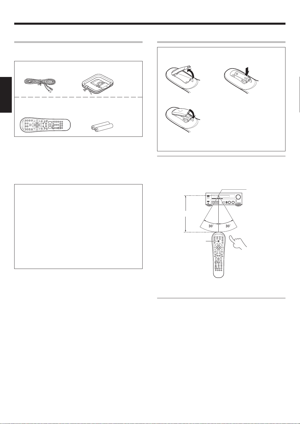
Unpacking
Unpack the unit carefully and make sure that all accessories are
present.
FM indoor antenna (1) AM loop antenna (1)
ENGLISH
Remote control unit (1) Batteries (R6/AA) (2)
RC-R0821
If any accessories are missing, or if the unit is damaged or fails to operate,
notify your dealer immediately. If the unit was shipped to you directly,
notify your shipper immediately. Kenwood recommends that you retain
the original carton and packing materials in case you need to move or ship
the unit in the future.
Keep this manual handy for future reference.
Memory back up function
Please note that the following items will be deleted from the unit's
memory if the power cord is disconnected from the AC outlet for
approximately 1 day.
• Power mode
• Input selector settings
• Picture output
• Speaker ON/OFF
• Volume level
• BASS, TREBLE, INPUT level
• TONE ON/OFF
• LOUDNESS ON/OFF
• Dimmer level
• MD/TAPE settings
• Listen mode setting
• Speaker settings
• Distance setting
• Input mode setting
• Sound mode settings
• Broadcast band
• Frequency setting
• Preset stations
• Tuning mode
• ACTIVE EQ mode
• SPEAKER EQ mode
Preparing the remote control
Loading the batteries
1 Remove the cover. 2 Insert the batteries.
3 Close the cover.
• Insert two AA-size (R6) batteries as indicated by the polarity markings.
Operation
When the STANDBY indicator is lit, the power turns ON when you press
the POWER
ON, press the key you want to operate.
RCVR
Operating range
(Approx.)
6 m
POWER RCVR
key on the remote control. When the power comes
Remote sensor
Infrared ray system
• When pressing more than one remote control key successively, press
the keys securely by leaving an interval of 1 second or more between
keys.
Notes
1. T he supplied batteries may have shorter lives than ordinary batteries
due to use during operation checks.
2. When the remote-controllable distance gets shorter than before,
replace both batteries with new ones.
3. Placing the remote sensor in direct sunlight, or in direct light from a
high frequency fluorescent lamp may cause malfunction.
In such a case, change the location of the system installation to prevent
malfunction.
EN
4

Before applying the power
Special features
True home theater sound
This receiver incorporates a wide variety of surround modes to bring you
maximum enjoyment from your video software. Select a surround mode
according to your equipment or the software you are going to play and
enjoy! ⁄
THX
THX mode activates proprietary THX features that help recreate the
cinematic experience in a home environment. fi
THX Surround EX
During THX Surround EX mode, film soundtracks that have been
encoded with Dolby Digital Surround EX technology are able to reproduce an extra channel which has been added during the mixing of the
program. This channel is called Surround Back.
THX Surround EX mode activates proprietary THX features that help
recreate the cinematic experience in a home environment. fi
Dolby Digital and Dolby Digital EX
The DOLBY DIGITAL mode lets you enjoy full digital surround from
software processed in the Dolby Digital format. Dolby Digital provides
up to 5.1 channels of independent digital audio for better sound quality
and more powerful presence than conventional Dolby Surround.
As for Dolby Digital EX, it creates six full-bandwidth output channels
from the 5.1 channel sources. This is done using a matrix decoder that
derives three surround channels from the two in the original recording.
For best results, Dolby Digital EX should be used with movie soundtracks
recorded with Dolby Digital Surround EX.
Dolby PRO LOGIC IIx and Dolby PRO LOGIC
DOLBY PRO LOGIC II, whilst totally compatible with its predecessor
PRO LOGIC, provides greater advantages in surround sound. It allows
user to enjoy the conventional stereo or Dolby Surround with a
convincing “5.1 like” presentation. PRO LOGIC II offers special features
for controlling the overall spatial, dimensionality and frontal sound field
imaging. PRO LOGIC II produces an impressive surround sound from
video software marked
from music CD. When listening to music, you will be able to enjoy the
experience of sheer STEREO surround sound.
DOLBY PRO LOGIC IIx enhanced DOLBY PRO LOGIC II’s features.
It creates 6.1 channel and 7.1 channel surround sound from stereo or
5.1 channel signals. This feature provides you an astonishing ambience
effect which makes you feel you are surrounded by natural sound.
Especially 7.1 channel surround sound can produce real back sound
from Surround Back speakers.
and three-dimensional space
II
DTS and DTS-ES
DTS (Digital Theater System) is a 5.1 channel digital audio format that
provides five full spectrum channels and one low-frequency (subwoofer)
channel for unprecedented clarity, optimum channel separation and a
(wide) dynamic range.
DTS-ES (Extended Surround) presents 6.1 channels surround system
with additional Surround Back channel which evolved from the
conventional 5.1 channels surround system. DTS-ES format that was
recorded in DVD, CD or LD comprises of two modes. DTS-ES Discrete
6.1 produce the discrete surround back which is completely independent
and DTS-ES Matrix 6.1 produces the surround back which synthesized
within the left and right surround channels using matrix technology.
DTS-ES has perfect compatibility with the conventional 5.1 channels
surround system. 6.1 channels surround with an additional surround
back presents a more natural presence and surround effects by
increasing the impression of the sound image from back.
Important:
When a DTS disc is played on a CD, LD or DVD player, noise may be
output from the analog output. It is recommended that you connect the
digital output of the player to the digital input of this unit.
DTS 96/24
DTS 96/24 made it possible to achieve a wide frequency range of over
40 kHz by increasing the sampling frequency to 96 or 88.2 kHz.
Moreover, DTS 96/24’s ability of 24 bit resolution offers the same
frequency band and dynamic range as 96 kHz/24 bit PCM.
DTS 96/24 is, as with conventional DTS Surround, compatible with
multi-channels. Therefore, sources recorded using DTS 96/24
technologies can be played in high sampling frequency, multi-channel
audio with ordinary DVDs and CDs.
Neo:6
Neo:6 is a new technology which was developed by DTS. It can produce
high grade 6 channels surround with an astonishing fidelity from 2
channels content. Neo:6 has 2 mode, "CINEMA" mode is for movie
playback and "MUSIC" mode is for music playback.
DSP surround modes
The DSP (Digital Signal Processor) used for this receiver incorporates
a variety of high quality adjustable sound fields, like “ARENA”, “JAZZ
CLUB”, “THEATER”, “STADIUM” and “DISCO”. It is compatible with
almost any kind of program source.
DVD 6-channel input
If you own a DVD player equipped with 6-channel output, this receiver
allows you to obtain the full surround sound impact of DVD source
material featuring multi-channel encoding. Since the source signals are
digital and each channel is input independently, the resulting ambience
is far superior to what can be achieved with conventional surround
sound systems.
ACTIVE EQ
ACTIVE EQ mode will produce a more dynamic sound quality in any
condition. You can enjoy a more impressive sound effect when ACTIVE
EQ is turned on.
SPEAKER EQ
SPEAKER EQ function is to adjust the receiver’s audio output
characteristics with the speakers’ characteristics which differs
depending on the size of the speakers. When activating the SPEAKER
EQ function, you will be able to enjoy a more natural and dynamic sound
experience even with small size speakers.
Universal IR (InfraRed) remote control
In addition to the basic receiver, the remote control supplied with this
receiver can also operate almost all of your remote controllable audio
and video components. Just follow the simple setup procedure to
register the components you have connected.
Video up conversion
This receiver can convert the incoming composit video signals to SVideo signal.
If your monitor TV has S-Video jacks, it is not necessary to do the
composit video connections, just use an S-Video cord to connect the
receiver and your monitor TV.
RDS (Radio Data System) tuner
The receiver is equipped with an RDS tuner that provides several
convenient tuning functions: RDS Auto Memory, to automatically
preset up to 40 RDS stations broadcasting different programs; station
name display, to show you the name of the current broadcast station;
and PTY search to let you tune stations by program type.
PTY (Program TYpe) search
Tune the stations by specifying the type of program you want to hear.
ENGLISH
EN
5
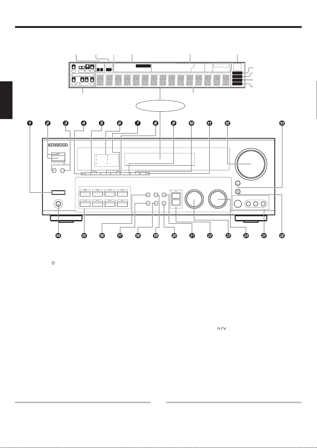
Names and functions of parts
Main unit
*Input channel indicators
The Input channel indicators
lights up to indicate the channels contained in the input
signal. The "S" indicator lights
when the surround component consists of a single channel.
ENGLISH
ON/STANDBY
A SPEAKERS B
STANDBY
POWER
-ON –
PHONES
Speaker
indicators
OFF
MUTE
indicator
L
CR
SW
LFE
SL S SB SR
*Input channel indicators
Output channel indicators
THX
DVD/6CH
AB
THX
SPEAKER EQ
ACTIVE EQ
SPEAKER EQ
SP
ACTIVE EQ
CLIP
indicator
MUTE
CLIP
DOLBY DIGITAL
DTS
DSP
DSP
PHONOCD/DVD
Input mode
indicators
OPTICAL 6CH INPUT
COAXIAL ANALOG 96kHzfs
TUNER
MD/TAPEVIDEO 3VIDEO 2VIDEO 1
STEREO
AUTO DETECT
INPUT MODE
DIMMER
SOUND
DSP MODE
Display
TONE
BAND AUTO
SETUP
MEMORY
DTS
MATRIX
DISCRETE
Listen mode
indicators
DOLBY DIGITAL
STEREO
PRO LOGIC
LOUDNESS
Frequency display
Input display
Preset channel display
Surround mode display
MULTI CONTROL LISTEN MODE
NEO:6
THX
Surround EX
RDS indicators
RDS
PTY
AUTO
MEMORY
STEREO
TUNED
VOLUME CONTROL
DOWN
MUTE
AV AUX
S VIDEO
VIDEO
AUTO indicator
MEMORY indicator
STEREO indicator
TUNED indicator
UP
L-AUDIO-R
1 POWER ON/OFF key (
Use to turn the main power on or off.
2 ON/STANDBY
key (
Use to turn the power ON/STANDBY when
the POWER is turned on.
STANDBY indicator
3 SPEAKERS keys £
Use to turn the A/B speakers on or off.
4 THX key ›
Use to switch the status of THX.
5 SPEAKER EQ key ¢
Use to select SPEAKER EQ’s setting.
6 Surround LED (light-emitting diode)
indicators
THX indicator fi
Lights when the THX mode has been chosen.
THX mode may or may not be activated
depending upon the applicable playback
mode.
SPEAKER EQ indicator ∞
Lights when the receiver is in the SPEAKER
EQ mode.
ACTIVE EQ indicator ¢
Lights when the receiver is in the ACTIVE EQ
mode.
DOLBY DIGITAL indicator ›
DTS indicator ›
Lights when the receiver is in the DTS mode.
DSP indicator ›
Lights when the receiver is in the DSP mode.
7 ACTIVE EQ key ¢
Use to select ACTIVE EQ’s setting.
8 DSP key ›
Use to select any of the DSP mode.
9 STEREO key ›
Use to switch the listen mode to STEREO.
0 INPUT MODE key 8
Use to switch between the full auto, digital
and analog inputs.
! DIMMER key
Use to select the REC MODE. §
Use to adjust the brightness of the display.
@ VOLUME CONTROL knob £
# MUTE key ¢
Use to temporarily mute the sound.
$ PHONES jack ∞
Use for headphone listening.
% Input Selector keys £
DVD/6CH, CD/DVD, PHONO , TUNER,
VIDEO 1, VIDEO 2, VIDEO 3, MD/TAPE
Use to select input sources.
Lights when the receiver is in the Dolby
Digital mode.
Standby mode
While the standby indicator is lit, a small amount of power is supplied to
the system to back up the memory. This is called standby mode. Under the
condition, the system can be turned ON by remote control unit.
^ SOUND key fl
Use to adjust the sound quality and the
ambience effects.
& BAND key ¶
Use to select the broadcast band.
* AUTO key ¶
Use to select the auto or manual tuning
mode.
( TONE key ¢
Use to switch the status of TONE control.
) MEMORY key •
Use to store radio stations in the preset
memory and to start the Auto Memory.
¡ SETUP key (
Use to select the speakers' settings etc.
™
fl
keys (
Use for selection adjustments during sound,
setup and preset channel functions.
£ MULTI CONTROL knob (
Use to control a variety of settings.
¢ LISTEN MODE knob ›
Use to select the listening mode.
∞ AV AUX (S VIDEO, VIDEO, L-AUDIO-R)
jacks *
§ AV AUX key *
Use to switch the input to AV AUX.
CAUTION
The power in this equipment will not be completely cut off from the
AC wall outlet when the main switch is turned OFF.
EN
6
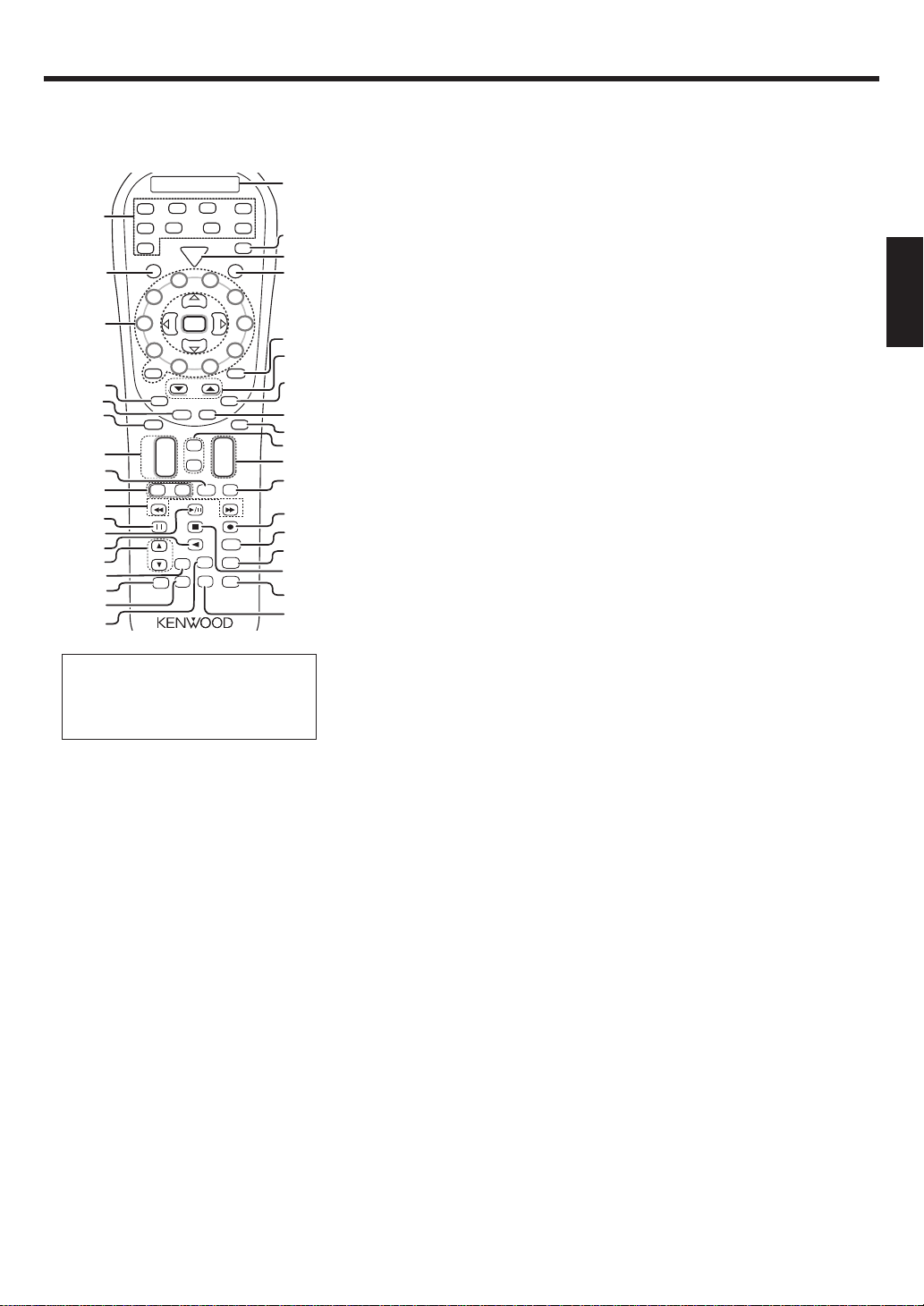
Names and functions of parts
Remote control unit
This remote control unit can be used not only for Kenwood products but also for other non-Kenwood products by setting the appropriate manufacturer’s
setup codes. ·
(
DVD
POWER
RCVR
Multi
Enter
Multi
Page
Tone
Sound
Band
Info
/
TV Input
Flip
Stereo
CD
6CH
DVD
MD
AV AUX
TAPE
)
TV
¡
o
w
P
e
V
r
T
5
P. Call
9
+ 100
PTY
TV Mute
OSD
Guide
Menu
+
VOL
–
Bass
Boost
Top MenuAuto
Setup
Loudness
Speaker
EQ
Input
Lea
Mode
™
6
7
£
8
¢
∞
§
Mute
¶
•
ª
º
⁄
¤
‹
›
n
r
fi
fl
,
£
1
2
3
4
5
6
7
8
9
0
!
@
#
$
%
^
VID3
VID2
PHONO
P
o
w
C
e
R
r
S
4
3
2
P. Call
1
0
+ 10
RDS Disp.
Return
Last / A/B
Exit
Disc Skip
Disc Sel.
Input Sel.
¢
+
CH
4
–
TV
+–
VOL
Tune – Tune +
Dimmer
Listen Mode
DSP
Mode
Active
THX
EQ
TUNER
VID1
&
*
If the name of a function on the receiver
is different from the one’s on the
remote control, the name of the remote
control key in this manual is indicated
in parentheses.
1 Source keys (MD/TAPE, CD/DVD, DVD/
TUNER,
6CH,
PHONO) ·
When press and hold for more than 3
seconds, they are used to select the
registered components.
Input Selector keys (MD/TAPE, CD/DVD, DVD/
6CH, TUNER, VID1, VID2, VID3, AV AUX,
PHONO)
When press and release in less than 3 seconds,
they are used to select the input sources.
2 SRC (
Use to turn the other source components on
or off.
3 Numeric keys ·
Provide functions identical to those of the
original remote control supplied with the
component you are controlling.
Multi (multi control) %/fi keys (
Use to control a variety of settings.
Use to operate other components.
P.Call @/# keys •
Use for selection adjustments during sound,
set up and preset channel functions.
Enter key
Use to operate other components.
4 Return key
Use to operate the DVD component.
Exit key
Use to operate other components.
VID1, VID2, VID3, AV AUX
) Power key
source
5 Disc Skip key
If CD is selected as the input source, this
key functions as the multi-CD player disc
skip key.
Last/ A/B key
If TAPE is selected as the input source,
this is A and B deck of a double cassette
deck.
Use to operate other components.
6 Disc Sel. key
Use to operate other components.
Input Sel. key
Use to operate other components.
7 CH +/– keys
Use to select the channels.
¢ / 4 keys
If CD, MD and DVD as the input source,
these keys function as skip keys.
8 TV Input key
Use when in TV operation.
9 TV VOL +/– keys
Use to adjust the TV’s volume.
0 1/¡ keys
If CD, MD or Tape is selected as the
input source, this key functions as
search keys.
Tune – / + keys ¶
Use to operate the tuner mode.
! 8 key
Use to operate other components.
Dimmer key
Use to select the REC MODE. §
Use to adjust the brightness of the display.
@ 3/8 key
If CD is selected as the input source, this
key functions as the play/pause key.
If MD or TAPE key is selected as input
source, this key functions as the play key.
Band key ¶
Use to select the broadcast band.
# 2 key
If Tape is selected, this key functions as
reverse play key.
Info/Flip key
Use to operate other components.
$ Listen Mode 5/∞ keys ›
Use to select the listening mode.
% DSP Mode key ›
Use to select any of the DSP mode.
^ Active EQ key ¢
Use to select ACTIVE EQ’s setting.
& THX key ›
Use to switch the status of THX.
* Stereo key ›
Use to switch the listen mode to STEREO.
( LCD (Liquid Crystal Display)
) TV key
Use to select the TV equipment.
¡ POWER RCVR (
Use to turn the receiver on or off.
™ TV Power key
Use to turn the TV on or off.
£ +100 key
Use to select the disc number with the
multi-CD player.
TV Mute key
Use to temporarily mute the TV sound.
¢ Page 5/∞ keys
Use to operate the DVD component.
RDS Disp. key ª
Use to receive RDS broadcast.
PTY key º
Use for PTY search.
receiver
) key (
fl
∞ OSD (on screen display) key
Use to operate the DVD component.
Guide key
Use to operate other components.
§ Menu key
Use to operate other components.
¶ Mute key ¢
Use to temporarily mute the sound.
• Tone key ¢
Use to switch the status of TONE control.
Sound key fl
Use to adjust the sound quality and the
ambience effects.
ª VOL +/– keys £
Use to adjust the receiver’s volume.
º Bass Boost key ¢
Use to select the maximum adjustment
setting for the low frequency range.
⁄ ÷ key
If MD or Tape is selected, this key
functions as record key.
If VCR is selected, this key functions as
record key when it pressed twice
sequentially.
Top Menu key
Use to operate the DVD component.
Setup key (
Use to select the speakers’ settings etc.
¤ Loudness key ¢
Use to switch the status of LOUDNESS.
‹ Speaker EQ key ¢
Use to select SPEAKER EQ’s setting.
› 7 key
If CD, MD, or TAPE is selected as the
input source, this key functions as the
stop key.
Auto key ¶
Use to select the auto or manual tuning
mode.
fi Learn key
Use to register other components.·
Use to memorize the operation of the
other remote controls. q
fl Input Mode key 8
Use to switch between the full auto,
digital and analog inputs.
ENGLISH
EN
7
Setting up the system
Make connections as shown in the following pages.
When connecting the related system components, be sure
to refer to the instruction manuals supplied with the
components you are connecting.
Do not connect the power cord to a wall outlet until all
connections are completed.
Notes
1.
Be sure to insert all connection cords securely. If their connections
are imperfect, sound may not be produced or there will be noise inference.
2. Be sure to remove the power cord from the AC outlet before plugging
or unplugging any connection cords. Plugging/unplugging connection
cords without disconnecting the power cord can cause malfunctions
ENGLISH
and may damage the unit.
3. Do not connect power cords from components whose power
consumption is larger than what is indicated on the AC outlet at the
rear of this unit.
Analog connections
Audio connections are made using RCA pin cords. These cables transfer
stereo audio signal in an “analog” form. This means the audio signal
corresponds to the actual audio of two channels. These cables usually
have 2 plugs on each end, one red for the right channel and one white for
the left channel. These cables are usually packed together with the
source unit, or are available at your local electronics retailer.
Microcomputer malfunction
If operation is not possible or an erroneous display appears, even
though all connections have been made properly, reset the
microcomputer referring to “In case of difficulty”. p
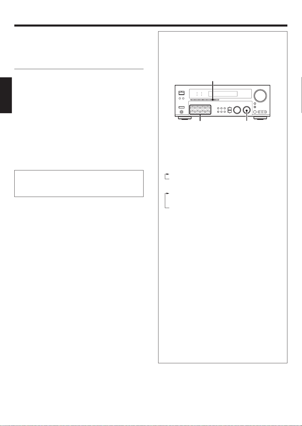
Input mode settings
CD/DVD, VIDEO 2, VIDEO 3 and DVD/6CH inputs each include jacks
for digital audio input and analog audio input.
The initial factory settings for audio signal playback for CD/DVD,
DVD/6CH and VIDEO 2 and VIDEO 3.
After completing connections and turning on the receiver, follow the
steps below.
INPUT MODE
Input Selector
1 Use the Input Selector keys to select CD/DVD, VIDEO 2,
VIDEO 3 or DVD/6CH.
2 Press the INPUT MODE key.
Each press switches the setting as follows:
In DTS play mode
1 FULL AUTO (digital input, analog input)
2 DIGITAL MANUAL (digital input)
In CD/DVD, VIDEO 2, VIDEO 3 or DVD/6CH play mode
1 FULL AUTO (digital input, analog input)
2 DIGITAL MANUAL (digital input)
3 6CH INPUT (DVD/6CH input)
4 ANALOG (analog input)
LISTEN MODE
Digital input:
Select this setting to play digital signals from a DVD, CD, or LD
player.
Analog input:
Select this setting to play analog signals from a cassette deck, VCR,
or record player.
Auto detect:
In “FULL AUTO” mode (AUTO DETECT indicator light up), the
receiver detects the digital or analog input signals automatically.
Priority is given to digital signal during input mode selection. The
receiver will select the input mode and listening mode automatically
during playback to match the type of input signal (Dolby Digital,
PCM, DTS) and the speaker setting. The OPTICAL and COAXIAL
indicator on the display will light up when digital signal is detected.
If the input signal is analog, the ANALOG indicator will light up.
To keep the receiver set to the currently selected listening mode,
use the INPUT MODE key to select “DIGITAL MANUAL” (manual
sound). However, even when this setting is selected, there may be
cases in which the listening mode is selected automatically to
match a Dolby Digital source signal depending on the combination
of listening mode and source signal.
At DIGITAL MANUAL, if the audio reproduction stops in the
middle due to change in the input signals, etc. press the LISTEN
MODE knob.
If the INPUT MODE key is pressed quickly, sound may not be
produced. Press the INPUT MODE key again.
EN
8
Setting up the system
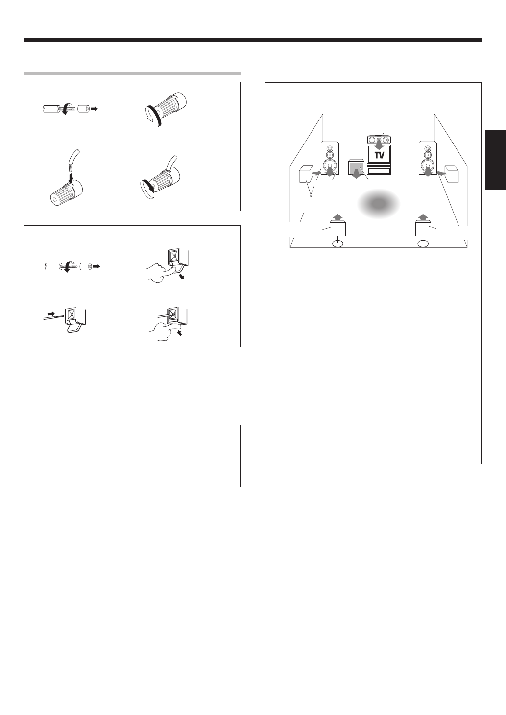
Connecting the terminals
1 Strip coating. 2 Loosen.
3 Insert. 4 Secure.
1 Strip coating. 2 Push the lever.
3 Insert the cord. 4 Return the lever.
• Never short circuit the + and – speaker cords.
• If the left and right speakers are connected inversely or the speaker
cords are connected with reversed polarity, the sound will be unnatural
with ambiguous acoustic imaging. Be sure to connect the speakers
correctly.
Speaker impedance
After confirming the speaker impedance indications printed on the
rear panel of the receiver, connect speakers with matching
impedance ratings. Using speakers with a rated impedance other
than that indicated on the rear panel of the receiver could result in
malfunctions or damage to the speakers or receiver.
Speaker placement
Center Speaker
Front Speakers
(L, R)
Surround Speakers
(L, R)
Surround Back
Left Speaker
Front (Left and Right) Speakers
Place at the front left and right of the listening position. Front speakers
are required for all surround modes.
Center Speaker
Place front and center. This speaker stabilizes the sound image and
helps recreate sound motion. Required for surround playback.
Surround (Left and Right) Speakers
Place at the direct left and right, or slightly behind, the listening
position at even heights, approximately 1 meter above the ears of the
listeners. These speakers recreate sound motion and atmosphere.
Required for surround playback.
Subwoofer
Reproduces powerful deep bass sounds.
Surround Back (Left and Right) Speakers
Place the speakers directly at the rear of the listening position. The
optimum position depends mainly on the room condition.
• Although the ideal surround system consists of all the speakers
listed above, if you don't have a Center Speaker or a Subwoofer, you
can divide those signals between the available speakers in the
speaker settings steps to obtain the best possible surround
reproduction from the speakers you have available. (
Subwoofer
Listening
position
Surround Back
Right Speaker
ENGLISH
EN
9
Setting up the system
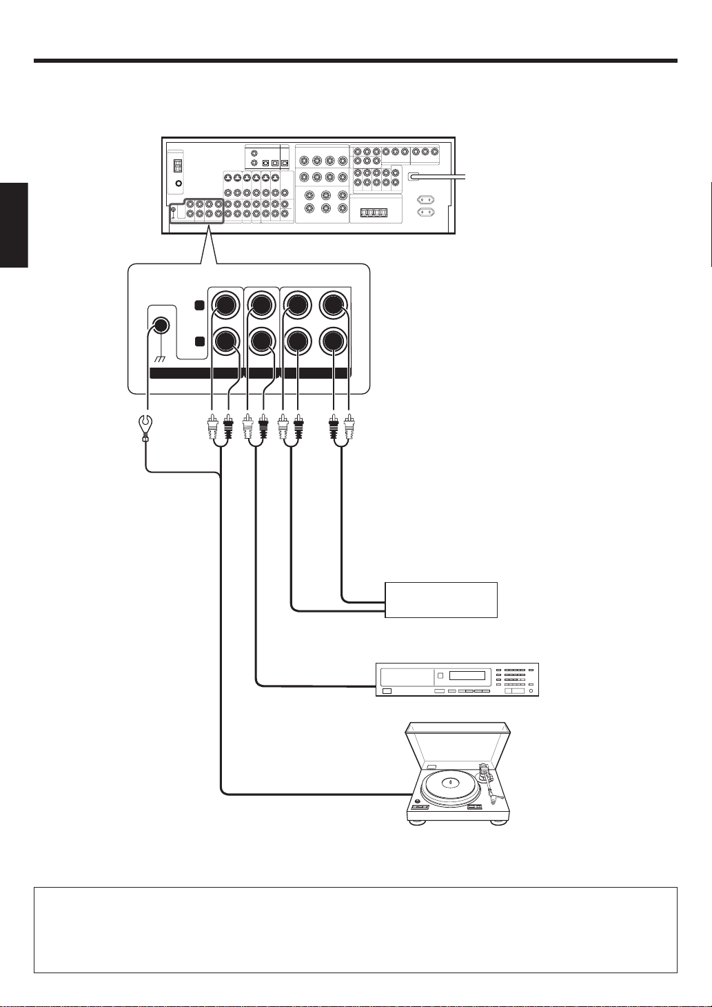
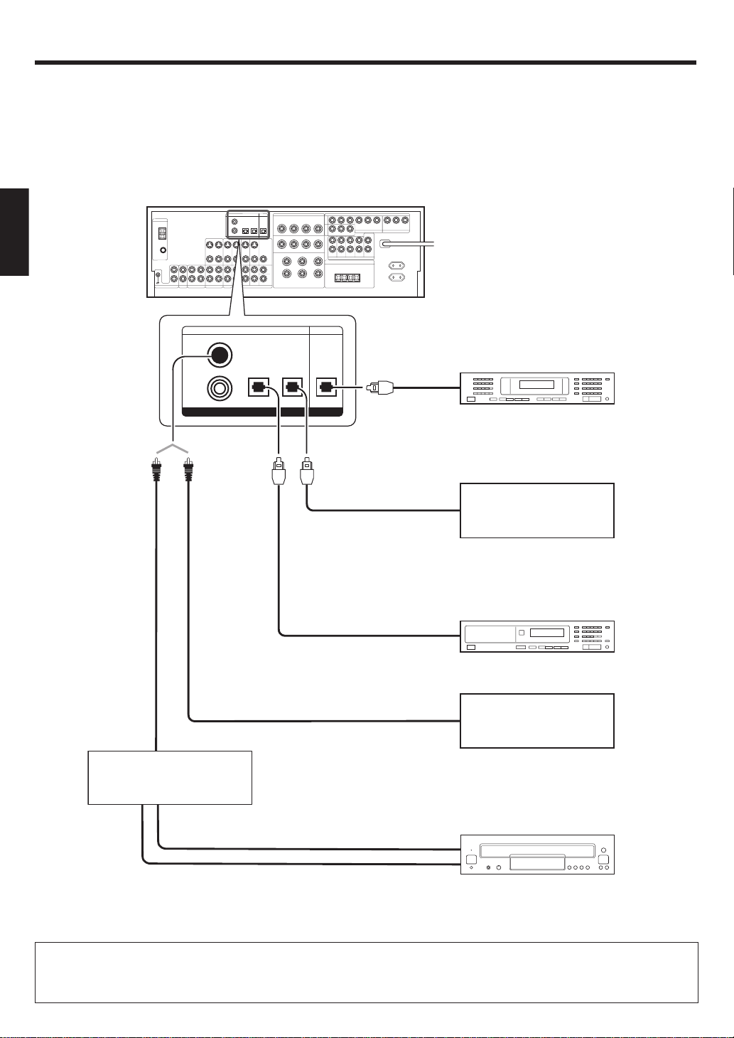
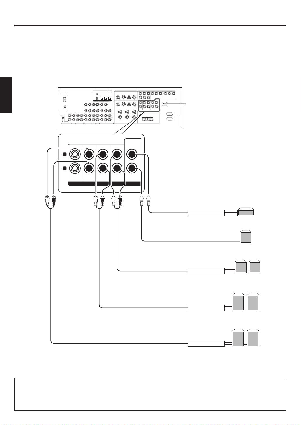
Connecting audio components
ENGLISH
L
RLR
PHONO
IN IN
CD/DVD
REC OUT PLAY IN
MD/TAPE
To AC wall outlet
OUT
OUT
Cassette Deck or
MD Recorder
IN
CD or DVD Player
OUT
Record Player
Moving coil (MC) cartridge
record player cannot be used
directly from the receiver unit.
It can only be used when another equalizer amplifier is connected.
CAUTION
Be sure to adhere to the following, or proper ventilation will be blocked causing damage or fire hazard.
• Do not place any objects impairing heat radiation onto the top of the unit.
• Leave some space around the unit (from the largest outside dimension including projection) equal to or greater than, shown below.
EN
10
Top panel : 50 cm Side panel : 10 cm Back panel : 10 cm
Setting up the system
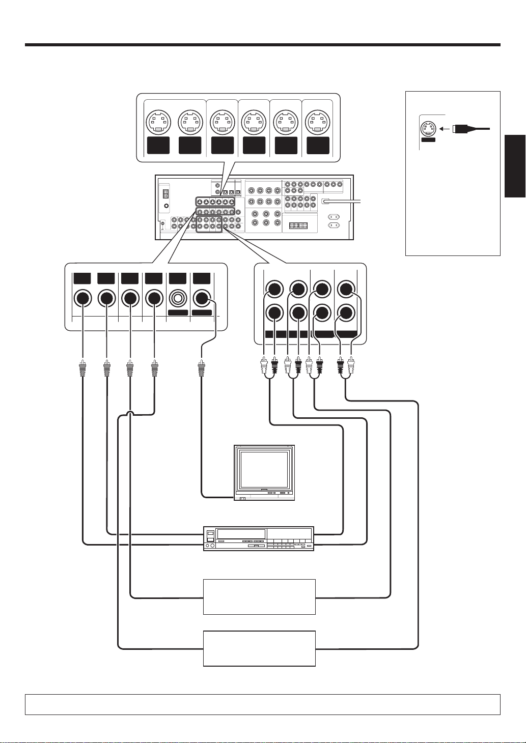
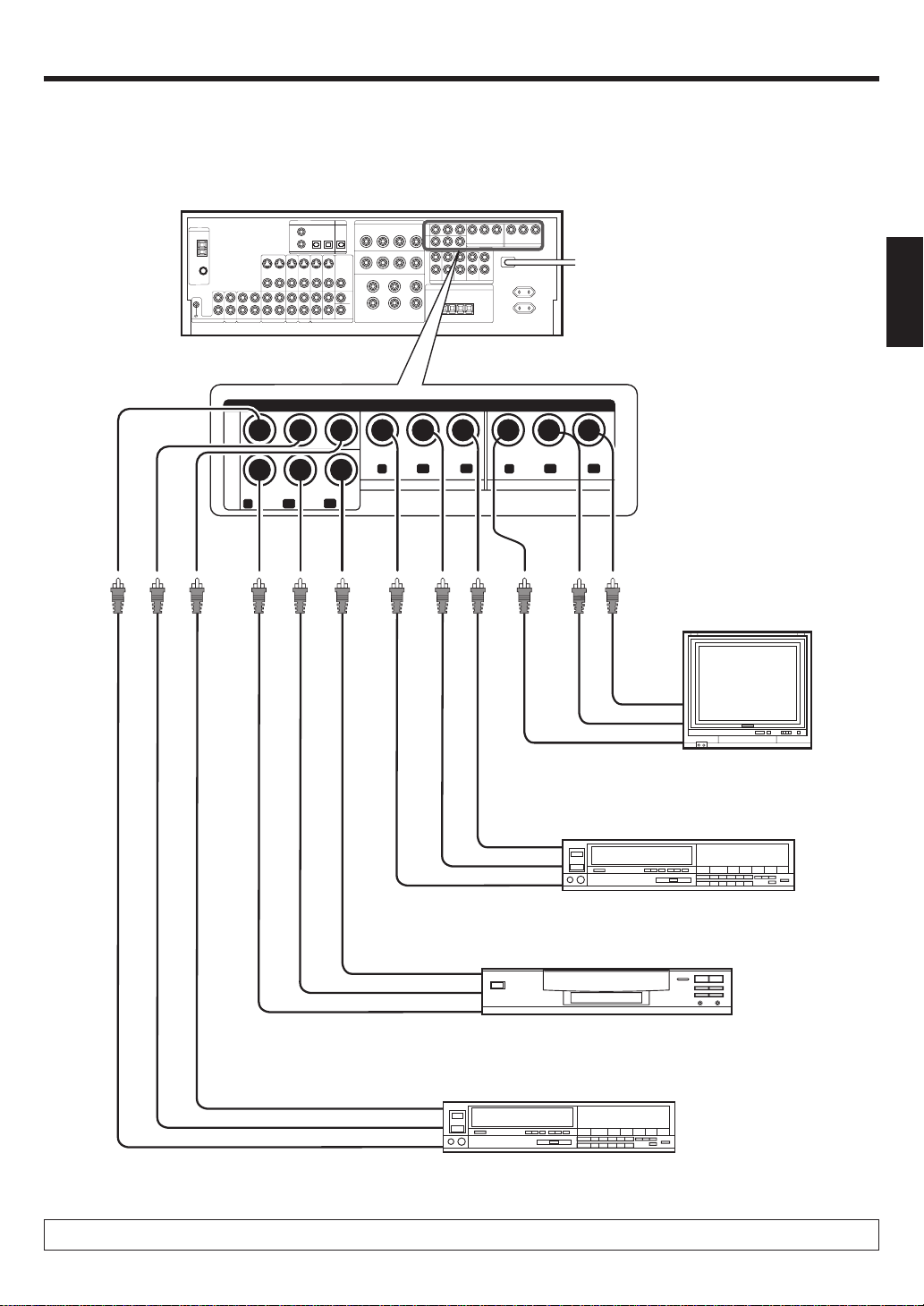
Connecting video components
S Video jacks
About the S VIDEO
Jacks
OUT
VIDEOINVIDEO
IN
VIDEO
S VIDEO
OUT
VIDEO
IN
VIDEOINVIDEO
DVD
S VIDEO
IN
VIDEO
MONITOR
OUT
VIDEO
S VIDEO
IN
VIDEO
S VIDEO
IN
VIDEO
S VIDEO
S VIDEO
OUT
IN
VIDEO
VIDEO 1 VIDEO 2 VIDEO 3
VIDEO
PLAY INPLAY INPLAY INREC OUT
S VIDEO
Use the S VIDEO Jacks to
make connections to
video components with
S VIDEO IN/OUT Jacks.
If you use the S VIDEO
•
jacks to connect your video
playback components, be
sure to use the S VIDEO
jacks when connecting
your monitor and video
recording components.
ENGLISH
Monitor TV
VIDEO
IN
Video Deck
OUT
IN
Video
OUT
Video
OUT
Video
DVD Player or LD Player
DVD Player or LD Player
IN
OUT
Audio
OUT
Audio
OUT
Audio
A video component with digital audio outputs should be connected to the VIDEO 2 or VIDEO 3 jacks.
11
EN
Setting up the system
Digital connections
The digital in jacks can accept DTS, Dolby Digital, or PCM signals. Connect components capable of outputting DTS, Dolby Digital, or standard PCM (CD)
format digital signals.
If you have connected any digital components to the receiver, be sure to read the “Input mode settings” section carefully. 8
ENGLISH
COAXIAL
DIGITAL
OUT
(AUDIO)
COAXIAL OPTICAL OPTICAL
VIDEO
2
DVD/
6CH
DIGITAL IN
Optical fiber
cable
VIDEO 3
OPTICAL
MONITORCD/DVD
DIGITAL OUT
Optical fiber cable
OPTICAL DIGITAL
IN (AUDIO)
Optical
fiber cable
OPTICAL DIGITAL
OUT (AUDIO)
OPTICAL DIGITAL
OUT (AUDIO)
COAXIAL DIGITAL
OUT (AUDIO)
MD Recorder
Component with DTS,
Dolby Digital, or PCM
OPTICAL DIGITAL OUT
Connect the video signal and analog
audio signals to the VIDEO 3 jacks.
(See “Connecting video components”.)
!
CD or DVD Player
Component with DTS,
Dolby Digital, or PCM
COAXIAL DIGITAL OUT
Connect the video signal and analog
RF digital demodulator
(Commercially available)
DOLBY DIGITAL RF
OUT (AUDIO)
PCM OUT
audio signals to the VIDEO 2 jacks.
(See “Connecting video components”.)
LD Player
To connect an LD player with a DIGITAL RF OUT, connect the LD player to a RF digital demodulator (commercially available).
Next, connect the DIGITAL OUT jacks of the demodulator to the DIGITAL IN jacks of the receiver.
Connect the video signal and analog audio signals to the VIDEO 2 or VIDEO 3 jacks. (See “Connecting video components”.)
EN
12
!
Setting up the system
Connecting video components (COMPONENT VIDEO)
If you have connected the receiver to a video component with COMPONENT jacks, you can get a better picture quality than by connecting to the S-VIDEO
jacks.
ENGLISH
VIDEO
3
IN
DVD
IN
COMPONENT VIDEO
Y
VIDEO 2 IN
CR
CB
Y
CRCB
Y
MONITOR OUT
CRCB
Monitor TV
(with component jacks)
CR IN
CB IN
Y IN
Video Recorder, DVD Recorder,
Satellite Cable Tuner & Game
CR OUT
Player (with component jacks)
CB OUT
Y OUT
CR OUT
DVD Player (with component jacks)
CB OUT
Y OUT
Video Recorder, DVD Recorder,
Satellite Cable Tuner & Game
CR OUT
Player (with component jacks)
CB OUT
Y OUT
When connecting the TV to the COMPONENT jacks, be sure to connect all the other components to the COMPONENT jacks.
13
EN
Setting up the system
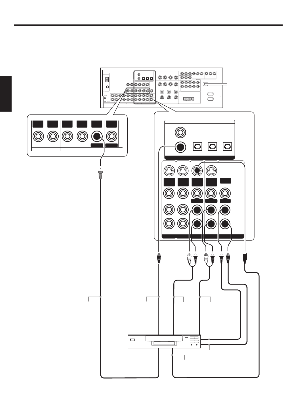
Connecting a DVD player (6-channel input)
If you have connected a DVD player to the receiver with digital connection, be sure to read the “Input mode settings” section carefully. 8
ENGLISH
OUT
VIDEOINVIDEO
IN
VIDEO
IN
VIDEOINVIDEO
DVD
OUT
VIDEO
MONITOR
COAXIAL OPTICAL OPTICAL
VIDEO
2
DVD/
6CH
DIGITAL IN
S VIDEO
S VIDEO
IN
VIDEO
PLAY IN
S VIDEO
FRONT
IN
VIDEO
PLAY IN
VIDEO 2 VIDEO 3
IN
VIDEO
DVD
VIDEO 3
S VIDEO
OUT
VIDEO
MONITOR
SURROUND
DVD/6CH INPUT
OPTICAL
MONITORCD/DVD
DIGITAL OUT
VIDEO
OUT
ROOM B
CENTER
SUB
WOOFER
14
VIDEO OUT
COAXIAL
DIGITAL OUT
(AUDIO)
DVD Player
FRONT
OUT L/R
S VIDEO
OUT
SURROUND
OUT L/R
CENTER
OUT
SUBWOOFER
OUT
S VIDEO cord
EN
Setting up the system
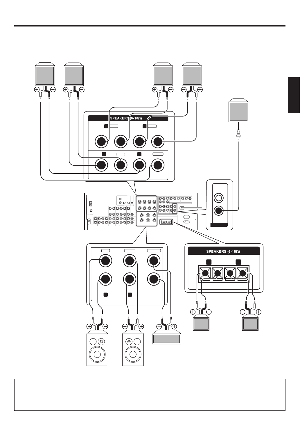
Connecting the speakers
Surround Back Speakers
RightLeft
SURROUND
SURROUND
BACK
Surround Speakers
Right
Left
ENGLISH
Powered
Subwoofer
GRAY
R
+
+
-
R
TAN
-
BLUE
L
-
-
+
BROWN
L
+
CENTER
SUB
WOOFER
GREENWHITERED
+
FRONT B
RL
-
++
RLCENTERFRONT A
Right
Center
Speaker
Right
Front Speakers A
• To make sure that each speaker has been connected properly, pay attention to the test tone from each speaker.
Refer to “5
Adjust the speaker volume level
.”. )
• This model is designed on the assumption that a pair of Surround Back Speakers is connected.
When use only one Surround Back Speaker, connect it with either speaker terminal of “SURROUND BACK L” or “SURROUND BACK R” and
increase the volume level of the test tone by 3 dB for the channel which has been connected. )
In this case, when “Dolby PRO LOGICIIx” is selected at LISTEN MODE, sound is output at the connected channel only.
Left
--
Left
Front Speakers B
15
EN
Setting up the system
PRE OUT connections
This receiver has additional PRE OUT jacks. These can be used for various purposes, but will need to be connected to an external power amplifier as
shown in the example below.
ENGLISH
CENTER
L
R
ROOM B FRONT
SURROUND SURROUND
BACK
PRE OUT
SUB
WOOFER
Power Amplifier
Power Amplifier
Power Amplifier
Power Amplifier
Center Speaker
Powered
Subwoofer
Surround Back
Speakers
R
L
Surround Speakers
LR
Front Speakers
R
L
• Connecting a speaker cord directly to a PRE OUT jack will not produce any sound from the speaker.
• To use the PRE OUT jacks, press only the SPEAKERS A key to the ON position.
• This model is designed on the assumption that a pair of Surround Back Speakers is connected.
When use only one Surround Back Speaker, connect it with either speaker terminal of “SURROUND BACK L” or “SURROUND BACK R” and
increase the volume level of the test tone by 3 dB for the channel which has been connected. )
In this case, when “Dolby PRO LOGICIIx” is selected at LISTEN MODE, sound is output at the connected channel only.
EN
16
 Loading...