

Kenwood VR-6070, KRF-X90600 Instruction Manual
AUDIO VIDEO SURROUND RECEIVER
VR-6070
KRF-X90600
INSTRUCTION MANUAL
KENWOOD CORPORATION
This instruction manualisfor some models. Model availability and features
(functions) may differ dependingonthe country and sales area.
About
the
suppliedremote control
Compared to standard remote controls, the remote control supplied
operation modes These modes enable the remote control to control other audio/video components. In
order to effectively use the remote control it is importanttoread
a proper understanding
Using the remote control without completelyunderstanding its design
modes may result
of
the remote control
in
incorrect operations.
and
how
to switch its operation modes (etc.).
with
this receiver
the operating instructions and obtain
and
how
to switch the operation
has
several
B60-5183-00
01
~~)
(K,P,T,M,Y,
X)
~~Y:.:
0110
Before
applying
the
power
it
Caution:
Read
this
operation.
page
carefullytoensure
safe
U.nits are
U.S.A.
Australia
Europe
China
Other
For the UnitedKingdom
2.
3 Do not cut
IMPORTANT: The
designed
and
Canada AC 120 V
and
U.K
and
Russia AC 220 V
countries
The mains plug contains a fuse For replacement, use only a 13Amp ASTA-approved (BS1362) fuse
The fuse cover
moulded plug.
is not suitable for the
short to reach a
approved extension lead or adapter, or consult your dealer.
If nonetheless the mains plug is cut off, remove the fuse and
dispose of the plug immediately, to avoid apossible shock hazard
by inadvertent connection to the mains supply
off
for
operationasfollows.
AC 240 V
AC 230 V
AC 110-120 I 220-240 V
Factoryfitted moulded mains plug
must
be refitted
the mains plug from thisequipment If the plug fitted
power
power
point, then obtainanappropriate safety
wiresinthe mains lead are colouredinaccordance
with
the following code
Blue : Neutral
Brown
'Live
when
replacing the fuseinthe
points in your home or the cable is too
switchable*
only
only
only
only
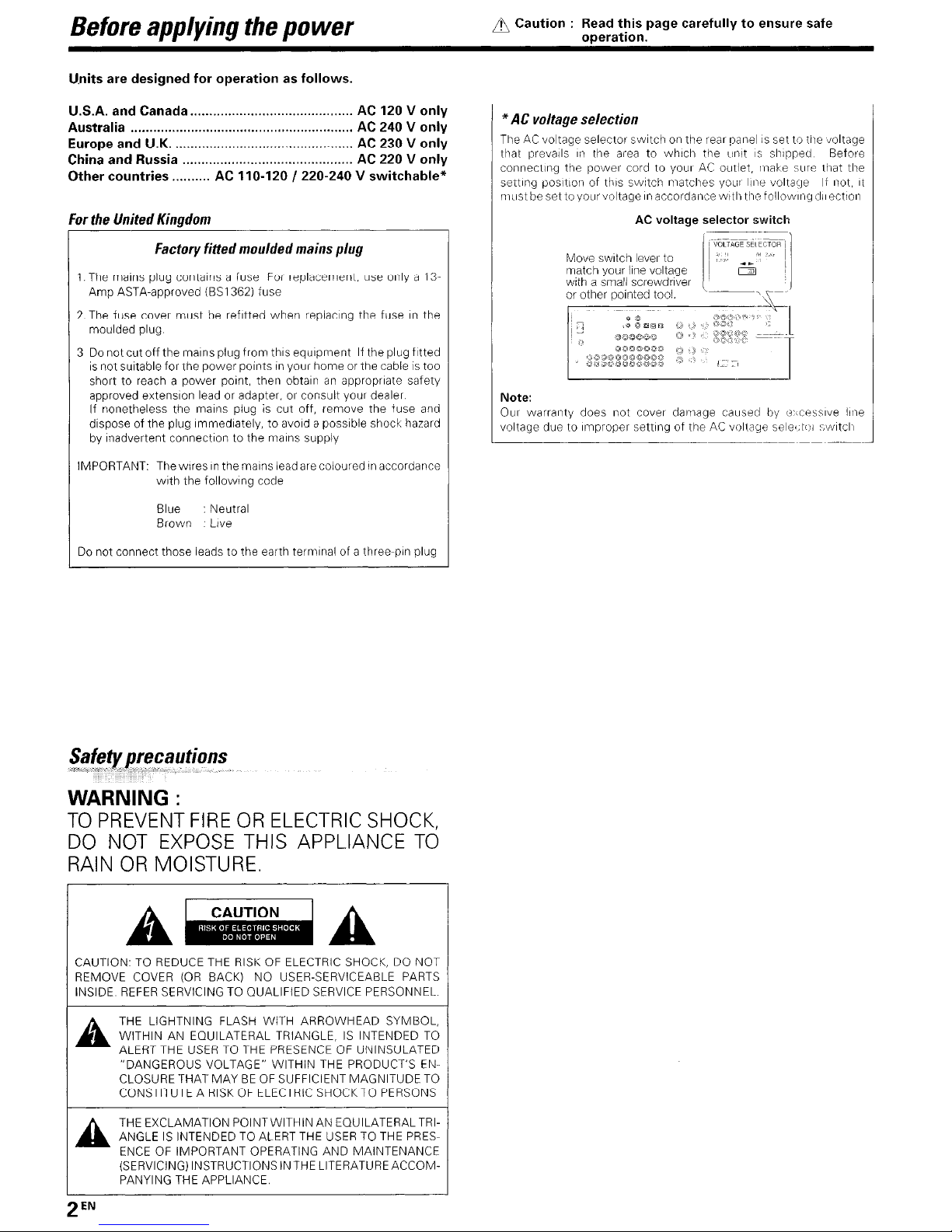
*AC voltage selection
TheACvoltage selector
that prevails
connecting the
setting position of this switch matches
must
in
be set to your voltage in accordancewltl) the following
Move switch lever to
match your line voltage
with a small screwdriver
or other pointed tool.
:J
(\
,
Note:
Our warranty does not cover damage caused by
voltage due to Improper setting of the
'------------------------_.
switchonthe rear panel is set to the voltage
the area to
power
00000"
0OOO(1)tl
g~ggggggggg
which
tile
cord to yourACoutlet, make sure that the
AC
voltage
,g
g
"OJg
0(:,
«(j
(OJ
,~"
unitisshipped Befol'e
YOLli' line
selector
'---~
000
,»
'U
388
"J
<:
,,»
"l
'..'
1';;:::-,
AC
voltage
volta~J8
switch
)'
~.
l
=,c"J'
(J>ccessive
seledol
If not, it
dilectioll
line
,~I/liitcll
__
._--
Do not connect those leads to the earth terminal of a three-pin plug
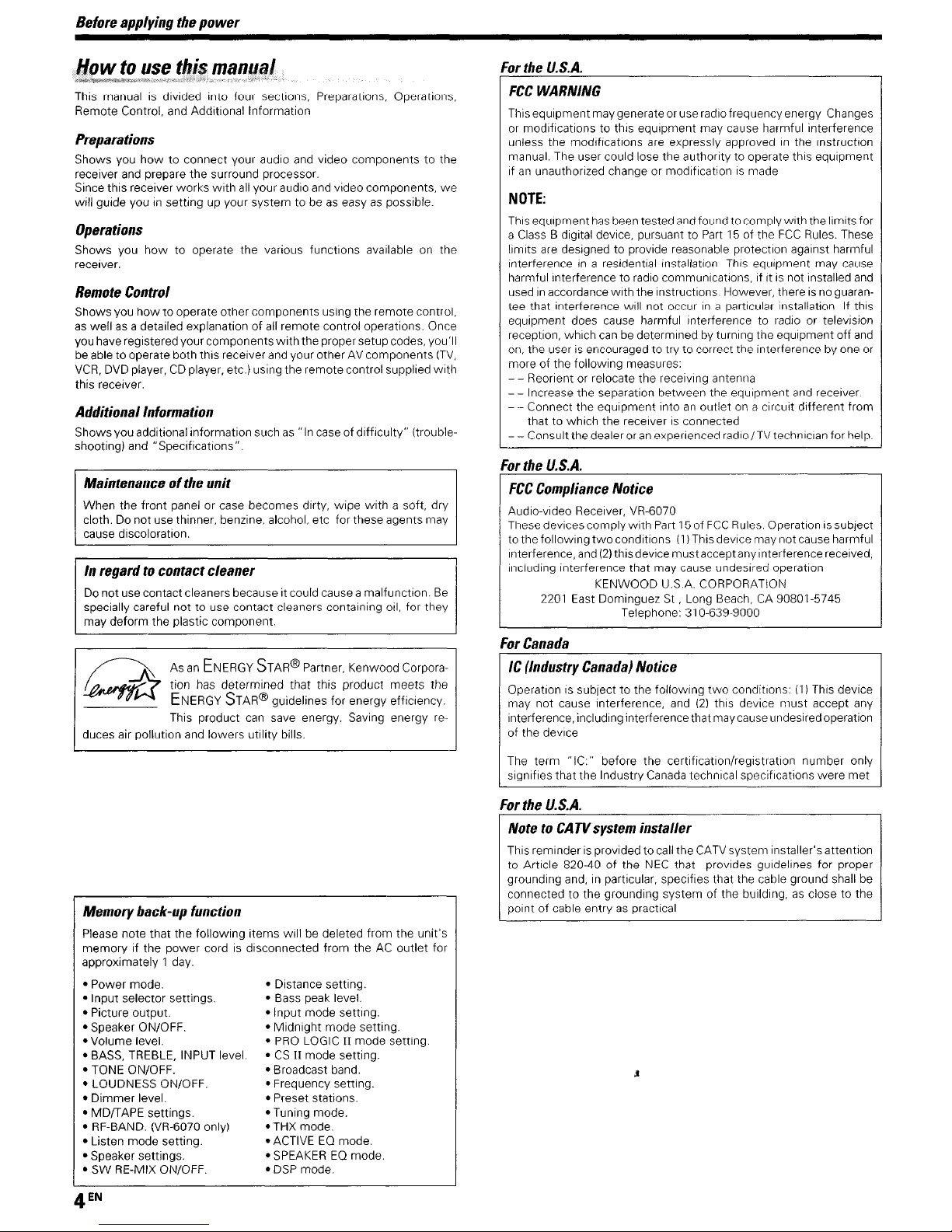
WARNING:
TO
PREVENT
DO
NOT
RAIN
OR
A~
CAUTION:TOREDUCE THE
REMOVE COVER
INSIDE
REFER
FIRE
EXPOSE
OR
ELECTRIC
THIS
SHOCK,
APPLIANCE
MOISTURE.
A
(OR
SERVICINGTOQUALIFIED SERVICE PERSONNEL.
RISKOFELECTRIC SHOCK, DO NOT
BACK) NO USER-SERVICEABLE PARTS
TO
THE
LIGHTNING FLASH WITH ARROWHEAD SYMBOL,
WITHIN
A
ALERT THE USERTOTHE
"DANGEROUS VOLTAGE" WITHIN THE PRODUCT'S
CLOSURE THAT
CONSTITUTE A
THE
ANGLE
A
ENCEOFIMPORTANT OPERATING AND MAINTENANCE
(SERVICING) INSTRUCTIONS
PANYING
AN
EQUILATERAL TRIANGLE,ISINTENDED
MAYBEOF
RISKOFELECTRIC SHOCKTOPERSONS
EXCLAMATION POINTWITHINAN EOUILATERAL TRI-
IS
INTENDED TO ALERT
THE
APPLIANCE.
PRESENCEOFUNINSULATED
SUFFICIENT MAGNITUDE TO
THE
IN
THE
LITERATURE ACCOM-
USERTOTHE
TO
EN-
PRES-

Before
applying
Contents
the
power
Caution:
Read the pages marked 6 carefullytoensure
safe operation.
6
Before
1-,
Safety precautions 2
Unpacking 3
How
Special
Names
Main Unit
Remote control unit
(RC-R0814)
Remote control unit
(For
the UK.onlyl 8
Settingupthe
Connecting audio components 10
Connecting video components
Digital connections
Connecting video components
(COMPONENT VIDEO) 13
Connecting a DVD player (6-channel Input)
Connecting the speakers 15
Connecting the terminals 16
Connecting to another room (ROOMB). 17
PRE
OUT connections. 18
Connecting theRFantenna and external
IR Repeater (For VR-6070 only) . 19
Connecting to theAVAUX
Connecting the antennas 20
COllnecting the system control
Preparing the remote control
RF
remote control function
Preparing
Speaker settings 23
Normal
Preparing for playback 26
Listening to a source component 26
Adjusting the sound
Recording
Recording audio lanalog sources) 29
Recording
Recording audio (digital sources) 29
Listeningtoradio
Tuning (non-RDS) radio stations.
USing
(For the
Presetting radio stations manually
ReceiVing preset stations
ReceiVing preset stationsinorder(PCALl)
Using the
(For the U K only).
Presetting
MEMORY)
Tuning by Program TYpe
(For
the U K only)
Ambience
Surround
Surround play 36
DVD 6-channel playback
Convenienl funclions 38
Basic
remote
applying
to use this manual .
features.
and
functionsofparts
(KRF-X9060D)
system
for
surround
playback
,
video.
RDS
(RadiO
UK
only). 30
RDS
RDS
(For
effects
modes.
control
If
the
power
IRC-R0813)
(RC-R0815)
sound
broadcasts
Data System)
DISP (Display) key
stations
the
UK
(RDS
only) .
operations
components
Registerrng setup codes for other
components.
Operating other components
Storing the remote control code of
the other components
..
(VR-6070)
. 7
(KRF-X9060D)
Jacks
(For
VR-6070 only). 22
and
20
21
22
23
26
27
29
29
30
.30
.30
31
31
31
AUTO
32
(PTY
search)
32
33
33
37
for
other
41
41
42
.42
2
.4
5
6
.6
Setup code chart (RC-R0813) (VR-6070) and
(RC-R0814) (KRF-X9060D) .... 43
Setup code chart (RC-R0815) (KRF-X9060D)
(For
the UK.only)
CASSETTE deck.CDplayer &MDrecorder
operations.
Other components' operations.
In
caseofdifficulty
it.
Specifications
.....44
..
45
.46
48
50
9
11
12
14
Unpack the unit carefully and make surethat
FM
indoor antenna
RF
remote antenna
(For
VR-6070 only)
ForVR-6070
Remote control unit
RC-R0813
For KRF-X9060D
Remote control unit
RC-R0814
For KRF-X9060D
(For the
Remote control unit
RC-R0815
*
AC
plug adaptor
U.K. only)
(1)
(1)
(1)
(1)
(1)
(1)
AM
*Use to adapt the plug on the power
cord to the shapeofthe wall outlet.
(Accessory only forregions where use
is
necessary.)
If any acccessories are missing, or if the unitisdamaged or fails to
operate, notify your dealer immediately. If the unit was shipped to you
directly, notify your shipper immediately. Kenwood recommends that
you retain the original carton
move
or ship the unitinthe future
Keep this manual handy for future reference.
and
packing materialsincase you need to
all
accessories are present.
loop antenna
Batteries (R6/AA)
Batteries (R6/AA)
Batteries (R6/AA)
(1)
(2)
(2)
(2)
Before
applying
This manual is divided into four sections, Preparations, Operations,
Remote Control, and Additional Information
the
power
Preparations
Shows you
receiver
Since this receiver works with all your audio
will guide youinsetting up your system to beaseasyaspossible.
how
to connect your audio and video components to the
and
prepare the surround processor.
and
video components,
we
Operations
Shows you
receiver.
Remote
Showsyou
as
wellasa detailed explanationofall
you have registeredyour components
be
able to operate both this receiver
VCR,
this receiver.
how
to operate the various functions available on the
Control
how
to operate othercomponents using the remote control.
DVD
player,CDplayer, etc.) using the remotecontrol supplied
remote control operations. Once
with
thepropersetupcodes, you'll
and
your otherAVcomponents
(TV,
with
AdditionalInformation
Showsyou additional information suchas"In case ofdifficulty" (troubleshooting) and "Specifications".
Maintenanceofthe
When the front panel or case becomes dirty, wipe with a soft, dry
cloth. Do not use thinner, benzine, alcohol, etc for these agents may
cause discoloration.
In
regardtocontact
Do not use contact cleaners because it could cause a malfunction.
specially careful not to use contact cleaners containing oil, for they
may deform the plastic component.
~
~
duces air pollution
unit
cleaner
Be
AsanENERGY
tion has determined that this product meets the
ENERGY
This product can save energy. Saving energy
and
lowers utility bills.
STAR®
Partner, Kenwood Corpora-
STAR®
guidelines for energy efficiency.
re-
For
the
U.S.A.
FCC
WARNING
This equipmentmay generateor use radio frequencyenergy Changes
or
modifications to this equipment may cause harmful interference
unless the modifications are expressly approvedinthe instruction
manual. The user could lose the authority to operate this equipment
ifanunauthorized change or modificationismade
NOTE:
This equipment
a Class B digital device, pursuant to
limits
are
interferenceina residential installation This equipment may cause
harmful interference to radio communications, if itisnot installed
usedinaccordance with the instructions. However, thereisno
tee that interference will not occurina particular installation. If this
equipment does cause harmful interference to radio or television
reception, which
on, the userisencouraged to try to correct the interference by one
more of the following measures:
- - Reorient or relocate the receiVing antenna
- - Increase the separation between the equipment
- - Connect the equipment intoanoutlet on a circuit different from
that to which the receiverisconnected
- - Consult the dealeroran
For
the
FCC
Compliance
Audio-video Receiver, VR-6070
These devices comply
to the following
Interference,
including interference that may cause undesired operation
2201
For
Canada
IC
(Industry
Operationissubject to the following
may not cause interference, and
interference, includinginterferencethat may cause undesired operation
of
the device
has
been tested and found to comply with the limitsfor
designed to provide reasonable protection against harmful
can
be determined by turning the equipment off
experienced radio
Part15of the
/TV
FCC
Rules. These
and
receiver.
techniCian for help.
U.S.A.
Notice
with
two
and
(2)
KENWOOD U.S.A. CORPORATION
East Dominguez St , Long Beach,CA90801-5745
Canada)
Part15of
conditions
thisdevice mustaccept any interference received,
Telephone: 310-639-9000
Notice
FCC
(1)
Rules. Operationissublect
This device may not cause harmful
two
conditions: (1) This device
(2)
this device must accept any
guaran-
and
and
or
Memory
Please note that the following items willbedeleted from the unit's
memory if the power cordisdisconnected from theACoutlet for
approximately 1 day.
• Power mode.
• Input selector settings.
• Picture output.
• Speaker ON/OFF.
• Volume level.
•
• TONE ON/OFF.
• LOUDNESS ON/OFF.
• Dimmer level.
•
• RF-BAND. (VR-6070 only)
• Listen mode setting.
• Speaker settings.
•SWRE-MIX ON/OFF
back-up
BASS,
TREBLE, INPUT level.
MDIT
APE
settings.
function
• Distance setting.
• Bass peak level.
• Input mode setting.
• Midnight mode setting.
•
PRO
LOGICIImode setting.
•CSII
mode setting.
• Broadcast band.
• Frequency setting.
• Preset stations.
• Tuning mode.
.THX
mode.
• ACTIVEEOmode.
•
SPEAKEREOmode.
•
DSP
mode.
The term
signifies that the Industry
For
NotetoCATVsystem
This reminderisprovided tocall the
to Article 820-40ofthe
grounding and,inparticular, specifies that the cable ground shall be
connected to the grounding systemofthe building,asclose to the
pointofcable entryaspractical
the
"IC:"
U.S.A.
before the certification/registration number only
Canada
technical specifications
were
installer
CATV
NEC
that provides guidelines for proper
J
system installer's attention
met
Before
applying
the
power
Special
True
This receiver incorporates a
maximum enjoyment from your video software Select asurround mode
according to your equipment or the software you are going to play and
enjoy'
THX
THX SurroundEXisanextensionofTHX
by Lucasfilm THX
a
new
to home theater audio
This system features Re-equalization (Re-EOl. Timbre Matching, Adaptive Decorrelation, Bass
Time Synchronizatiol). which reproduces similar cinematic effects
the home environmel)t
Do/by
The DOLBY DIGITAL mode lets
software processedinthe Dolby Digital format Dolby Digital provides
up to 5 1 channels of independent digital audio for better sound quality
and more powerful presence than conventional Dolby Surround
As for Dolby Digital
from the 5 ) channel sources. Thisisdone using a matrix decoder that
derives three surround channels from the
For best results. Dolby DigitalEXshouldbeused
tracks recorded
Dolby
DOLBY
PRO
the user to
convlnclllg
tures for controlling the overall spatial, dimensionality and frontal sound
field imaging
from video software marked
space from musicCDWhen listening to music,you will be able to enjoy
the experience of sheer
o
TS-ES
The
Discrete Surround format whichisextended to
DTS-Matrlx 6 1
surroundwhichincludesanadditionalsurround-centerchannel developed
within surround-left
the original sound recorded similar to the theatrical effects
In
the
LDorDVD
playedinDigital Surround
Important.
When a
output from the analog output Itisrecommended that you connect the
digital
features
home
theater
Surround
dimel)slon of depth, spacious ambience and sound localization
Digital
PRO
PRO
LOGIC. provides greater advantages in surround sound It allows
DTS-ES
DTS-ES
DTS
outputofthe player to the digital input of this unit
sound
wide
variety of sU('found modes to bring you
-i.l-~
EX
and
Dolby Laboratories. It allows youtoexperience
Peak
Level Manager and LoudspeakerPosition
and
Do/by
Digita/
EX.itcreates six full-bandwidth output channels
with
Dolby Digital Surround
LOG/C
IJ
LOGIC
II,
whilst
totally compatible with its predecessor
enJoy
the conventional stereoorDolby Surround
"51
like" presentation
PRO
LOGICIIproducesanimpressive surround sound
(Digital Theater System-Extended Surround)isa6 1-channel
and
DTS
and
mode. the 5 1or 6 1channel digital input from a
diSC
(carrying the
discisplayed on a
DOl
STEREO
NE06.Itis
surround-right
"DTS"or"DTS-ES" marking) can
CD,LDor DVD player, noise may be
which was jointly developed
EX
yOLi
enjoy full digital surround from
twointhe original recording
PRO
LOGICIIoffers special fea-
DOUIY
SURAOUND
surround sound
a 6 1 channel expanded from 5 1
DTS-ES
with
DTS-ES
movie sound-
Discrete 6
EX
I and three-dimensional
will be able to produce
with
DTS
CD.
be
DSP
surround
The
DSP
a varietyofhigh quality adjustable sound fields. like "ARENA", "JAZZ
CLUB", "THEATER",
almost any kindofprogram source
DVD
6-channel
If you
ownaDVD
allows youtoobtain the full surround sound impactofDVD source
material featuring multi-channelencoding. Since the source signals are
digital and each channel is input independently, the resulting ambience
is
far superior to what can be achieved
In
sound systems.
ACTIVE
ACTIVEEOmode will produce a more dynamic sound qualityinany
condition
EO
is turned on during Dolby Digital
SPEAKER
The
SPEAKEREOfunction will automaticallydetect the various features
of eacll speaker and etrectively creales a stereoscopic sound effect.
Remote
Some of the remote controls have
UniversallR
In
addition to the basic receiver, the remote control supplied
receiver can also operate almost
a
1.
and video components Just follow the simple setup procedure to
register the components you have connected
RF
remote
YOLI
can
remote control The controllable range of the remote control is not
influenced by surroundings suchasdistance oranobstruction.
RDS
(Radio
The receiverisequipped withanRDS
convenient tuning functions
presetupto 40
name display,toshow
and
PTY
PTY
(Program
Tune the stations by specifying the type of program you
modes
(Digital Signal Processor) used for this receiver incorporates
"STADIUM"
and "DISCO"
Itiscompatiblewith
input
player equipped
with
6-channel output, this receiver
with
conventional surround
EO
You
can enjoyamore impressive sound
and
DTS
effect
playback.
when ACTIVE
EO
control
two
kindsofsignal
(/nfraRed)
signal
operate the receiver by sendingRFremote signal from the
Data
RDS
search to let you tune stations by program type.
TYpe)
remote
(For
VR-6010
System)
stations broadcasting different programs; station
you the nameofthe current broadcast station,
search
control
all
of your remote controllable audio
only)
tuner
(For
the
U.K,
only)
RDS
(For
tuner that provides several
Auto Memory. to automatically
the
U,K.
only)
want
with
to hear.
this
Multi
channel
(SRS
Circle
SRS
Circle Surround
ing in the
channel. surround sound playback from astereo sourceorconventional
surround-encoded video source
digital sound/DTS multi-channel sound
you can listen to audio
your multi-speakers
SRS
Circle Surround
surround
Surround
CS-6
1™ system, enabling youtolisten to realistic. multi-
sound
II
Ce)CS
lI™
improves on its predecessor
CDs.
MDs. Broadcast and HomeTheater using
You
will discover a
II
You
)
already
with
your multi-speakers.
new
CS-5
1™ result-
enJoy
listening to Dolby
type of sound through
Now
Names
and
functionsofparts
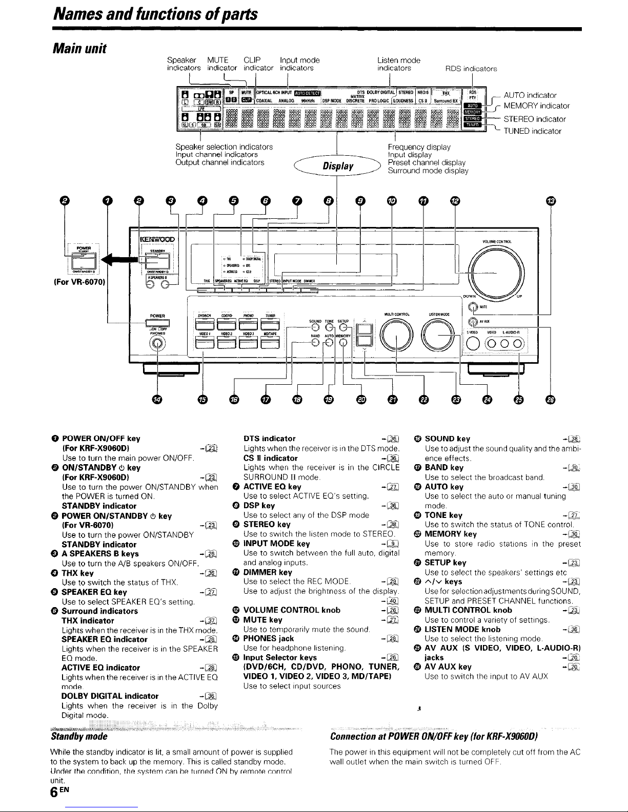
Main
unit
(For VR·60701
Speaker
indicators indicator indicator indicators
MUTE
CLIP Input mode
PTICAL!CIt
.~OAXIA~.,
~=-'~="'~="'=""~~=F"'=~~'"'""~
Speaker selection indicators
Input channel indicators
Output channel indicators
====~d=d---I======I
POWER
INPUT
..
ANAlo:G..
L
rmIiJDI&,
96kHzls
~OSP
MOOE
Display
.lil-
OlSCllm
Listen mode
indicators
J
.- -'..'
PROLOGlC
LOUDNESS
CS.
III
""====
Frequency display
Input display
Preset channel display
Surround mode display
RDS
indicators
bs=
S"",undEX
...
~
.......
....
"=""'=·"""''''''''''''''1
AUTO
I E
M M YIndicator
::
STEREO
'--
TUNED
'''''''''0<
OR
Indicator
Indicator
o POWER ON/OFF key
(For KRF·X9060DI
Use to turn the main power ON/OFF.
G ON/STANDBY
(For KRF·X9060DI
Use to turn the power ON/STANDBY when
POWERisturned
the
STANDBY
G POWER
(For VR·60701
Use to turn the power ON/STANDBY
STANDBY
<!:J
key
indicator
ON/STANDBY
indicator
ON
<!:J
key
e A SPEAKERS B keys
Use
to turn the AlB speakers ON/OFF.
o THX
key
Use to switch the status of
THX.
o SPEAKER EO key
Use to select
G
Surround
THX
Lights when the receiverisin
SPEAKER EO
Lights when the receiverisin
EO
mode.
ACTIVE EO
Lights when the receiverisin
mode.
DOLBY DIGITAL
Lights when the receiverisin
Digital mode.
indicators
indicator
SPEAKER
indicator
indicator
indicator
EO's setting.
the
THX
the
SPEAKER
the
ACTIVE
the Dolby
-CUJ
-CUJ
-CUJ
-~
-00
-em
-iJll
mode.
-~
-~
EO
-~
DTS
indicator
Lights when the receiverisin
CSnindicator
Lights when the receiverisin
SURROUNDIImode.
G ACTIVE EO
Use to select
Q DSP key
Use
Q STEREO key
Use to switch the listen mode to
El
INPUT MODE key
Use to switch between the full auto, digital
and
o DIMMER
Use to select the
Use to adjust the brightness of the display.
key
ACTIVE
to
select
any
analog inputs.
key
of the
REC
o VOLUME CONTROL
o MUTE
key
Usetotemporarily mute the sound.
the
DTS
the
EO's setting.
DSP
mode
STEREO.
MODE. -lliJ
knob
e PHONES jack
Use for headphone listening.
~
Input
Selector keys
(DVD/6CH,
VIDEO 1, VIDEO 2, VIDEO 3, MD/TAPE)
Use to select input sources
CD/DVD,
PHONO, TUNER,
-Q[)
mode.
-00
CIRCLE
-CW
-00
-l$J
-~
-em
-~
e SOUND
Use to adjust the sound quality
ence effects.
f9
BAND
Use to select the broadcast band.
(JJ)
AUTO key
Use to select the autoormanual tuning
mode.
(JJ)
TONE key
Use to switch the status of
fi)
MEMORY key -Q.[)
Use to store radio stationsinthe preset
memory.
~
SETUP
Use to select the speakers' settings etc
fJ
A/v
Use for selectionadjustments during SOUND,
SETUP
fl)
MULTI
Use to control avariety of settings.
If)
LISTEN MODE
Usetoselect the listening mode.
a;
AV
jacks
~
AV
Use to switch the input toAVAUX
key
key
key
keys
and
PRESET
CONTROL
AUX(SVIDEO, VIDEO, L·AUDIO-R)
AUX
key
CHANNEL functions.
knob
knob
and
TONE
control.
-Q[)
the ambi-
-~
-iJ9J
-~
-~
-(JjJ
-CW
-~
-~
-Q[;
While the standby indicatorislit. a small amount of power is supplied
to the system to back
Under the condition, the system
unit.
EN
6
up
the memory.
Thisiscalled standby mode.
canbeturnedONby remote control
C~nn8ction
The
powerinthis equipment will notbecompletely cut off from the
wall outlet when the main switchisturned
~'t'POWtR;ON/OFF
key (for
KRF-X9060D)
OFF.
AC
Names
and
functionsofparts
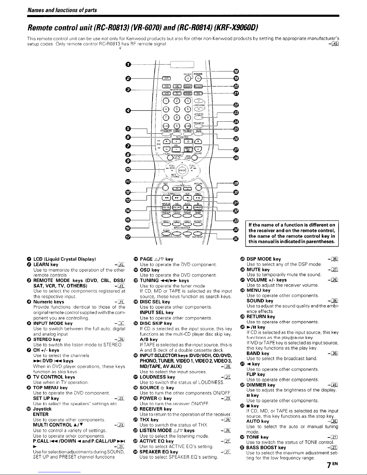
Remote
This remote control unit
setup codes Only remote control RC-R0813
control
unit
(RC-R0813)
canbeuse not only for Kenwood products but also for other non-Kenwood productsbysetting the appropriate manufacturer's
(VR-6070)
hasRFremote signal
(
and
(RC-R0814)
(KRF-X9060D)
-CSl
o
LCD
(Liquid Crystal Display)
6 LEARN key
Use to memorize the operation of the other
remote controls
Q REMOTE
SAT,VCR,TV,
Usetoselect the components registered at
the respective
MODE
Input
keys (DVD,
OTHERS)
CBl,
-~
DSS/
-~
Q Numeric keys -::ll:,
Provide functions identicaltothose of the
originaIremote control supplied withthe component you
9 INPUT
Use to switch between the full auto. digital
and analog input
e STEREO key
Usetoswitch the listen mode to
o
CH
Use to select the channels
~~I
WheninDVD
function
o
TV
Use wheninTV
o TOP
Use to operate the
SET UP key
Use to select the speakers' settings etc.
ll1)
Joystick
ENTER
Use to operate other components.
MULTI
Usetocontrol a variety of settings.
Usetooperate other components.
P.CALL
~
Use for selection adjustments during SOUND,
SETUPand
are
controlling.
MODE
key
+/- keys
DVDI~keys
CONTROL keys
MENU
player operations. these keys
as
skip keys
operation.
key
CONTROL
I~~
/DOWN~and P.CALL/UP
PRESET
DVD
component
A/~
channel functions
-cr::
-~
STEREO
-cv:
-cw
~
-~
mPAGE
b./'V
Use to operate the
key
DVD
component.
o OSD key
Use to operate the
e
TUNING
Use to operate the tuner mode
If
source, these keys functionassearch keys.
In
DISC SEL key
Usetooperate other components.
INPUT SEL key
Use to operate other components.
~/~
CD.MDor
DVD
component
keys
TAPEisselectedasthe input
o DISC SKIP key
IfCDis
selectedasthe input
functionsasthe multi-CD player disc
A/B
key
If
TAPEisselectedasthe input source, this
A
and
f!J
B deck of a double cassette deck.
INPUT
SELECTOR
PHONO,TUNER, VIDEO 1,VIDEO2,VIDEO3,
MD/TAPE, AV AUX)
Use to select the input sources
keys
G LOUDNESS key
Use to switch the status of LOUDNESS.
o SOURCE
Use to turn the other components ON/OFF
o POWER
Use to turn the receiver ON/OFF.
(1)
RECEIVER key
Use to return to the operation of the receiver.
$
THX
Use to sWitch the status of
f1J
LISTEN
Use to select the listening mode.
(J)
ACTIVE EO key
Use to select
€!
SPEAKEREOkey
Use to select
key
<!>
key
<!>
key
MODE
b./'V
ACTIVE
SPEAKER
source,
(DVD/6CH, CD/DVD,
THX.
keys
EO's setting.
EO's setting.
this
skip
key
key.
-~
-eli,
-~
-~
-~
-lli
-:.n.
If the
name
the receiver and on the
the
this manualisindicatedin parentheses.
@)
DSP
Use to select any of the
€1
MUTE
Use to temporarily mute the sound.
~
VOLUME
Use to adjust the receiver volume.
€1
MENU
Use to operate other components.
SOUND
Use to adjust thesound quality and theambience effects
~
RETURN key
Use to operate other components.
@)
~/II
IfCDis
functions
is
IfMDorTAPEkey
this key functions
BAND key
Use to select the broadcast band.
$
~key
Use to operate other components.
FLIP
Usetooperate other components.
G
DIMMER
Usetoadjust the brightness of the display.
II
key
Use to operate other components.
G.
key
If
CD,
source, this key functions
AUTO
Usetoselect the autoormanual tuning
mode.
el
TONE key
Use to switch the status of
G)
BASS BOOST key
Use to select the maximum adjustment setting for the low frequency range.
of a functionisdifferent on
name
of the
remote
MODE
key
key
+/- keys
key
key -Oil
key
selectedasthe input source, this key
as
the play/pause key
is
selectedasinputsource,
as
the play
key
key
MD, or
TAPE
IS selected
key
remote
control key
DSP
mode.
key.
as
as
the stop key.
TONE
control,
in
-00
-WJ
-00
-~
the input
-Q[)
-CllJ
control.
-em
Names
and
functionsofparts
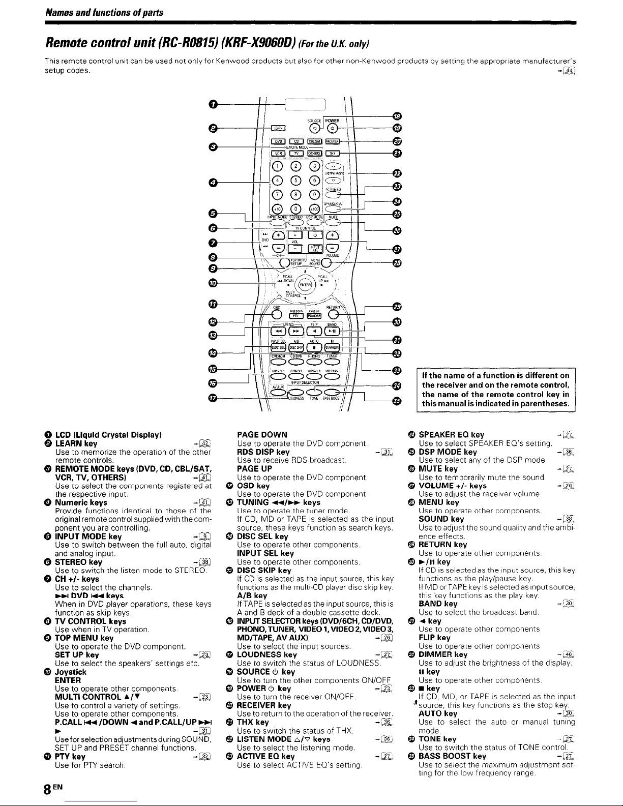
Remote
This remote control unit
setup codes.
control
unit
(RC-R0815)
canbeused notonly for Kenwood products but also for other non-Kenwood products by setting the appropriate manufacturer's
(KRF-X9060D)
(For
the
U.K.
only)
-CB::
o--.J-I----r-~
o
LCD
(Liquid Crystal Display)
e LEARN key -mJ
Use to memorize the operation of the other
remote controls.
€)
REMOTE
VCR,
Use to select the components registered at
the respective input.
e
Numeric
Provide functions identical to those of the
original remotecontrol supplied withthe com-
ponent you
e
INPUT
Use to switch between the full auto, digital
and
e STEREO key
Use to switch the listen mode to
o CH
Use to select the channels.
~DVD~keys
WheninDVD
function
Q
TV
Use wheninTV
o
TOP
Use to operate the
SET UP key
Use to select the speakers' settings etc.
MODE
TV,
MODE
analog input.
+1-
keys
as
CONTROL keys
MENU
keys (DVD, CD, CBLISAT,
OTHERS)
keys
are
controlling.
key
player operations, these keys
skip keys.
operation.
key
DVD
-Clil
-CllJ
-00
-00
STEREO.
component.
-~
e Joystick
ENTER
Use to operate other components.
MULTI
CONTROL
Use to control a varietyofsettings.
Use to operate other components.
P,CALL~IDOWN
..
Use for selection adjustments during SOUND,
SETUPand
o
PTYkey
Use for
PTY
PRESET
search,
1..1"
... and P.CALL/UP
channel functions.
-CUJ
~
-ell)
-~
PAGE
DOWN
Use
to operate the
RDS DISP key -eli:
Use to receive
PAGE UP
Use to operate the
RDS
DVD
component.
broadcast.
DVD
component.
G OSD key
Use to operate the
e
TUNING
Use
If
source, these keys function
ID
DISC
Use to operate other components,
INPUT
Use to operate other components.
......1
to operate the tuner mode.
CD,
MD or
SEl
key
SEL key
DVD
keys
component.
as
search keys.
....
TAPEisselectedasthe input
e DISC SKIP key
IfCDis
selectedasthe
functionsasthe
AlB
key
,nAPEisselectedasthe input source, this
A
and
o INPUT
o LOUDNESS key -ell:
B deck of a double cassette deck.
SELECTOR
PHONO,TUNER, VIDEO1,VIDEO 2,
MD/TAPE, AV AUXI
Use
to select the Input sources.
Use to switch the status of LOUDNESS.
Input
source,
multi-CD player disc skip
keys (DVD/6CH, CD/DVD,
this
VIDEO
key
key.
-00
o SOURCE 6 key
Use to turn the other components ONIOFF
G POWER 6 key
Use to turn the receiver ON/OFF.
eI
RECEIVER key
Use to returnto the operationof the receiver.
~
THX key
Use to switch the status of
f1J
LISTEN
MODE
Use to select the listening mode.
@)
ACTIVE EO key -C'll;
Use to select
61\7
ACTIVE
THX.
keys
EO's setting,
-m:;
-OC
-IJ:§:)
If
the
name
the receiver and on
the
this manualisindicatedin parentheses,
fl) SPEAKER EO key -Cll,
Use to select
$ DSP
Use to select
f'1)
MUTE
Use to temporarily mute the sound
Qi
VOLUME
Use to adjust the receiver volume.
I!li
MENU
Use to operate other components.
SOUND
Use
to adjust thesound quality
ence effects.
lii
RETURN key
Use to operate other components.
G ..
III
IfCDis
functions
If
MDorTAPE keyisselectedasinputsource,
this key functions
BAND key -:J.gJ
is
3,
Use to select the broadcast band.
G
...
key
Use to operate other components
FLIP
Use
to operate other components
fj
DIMMER
Use to adjust the brightness of the display.
II
key
Use to operate other components.
G.
key
If
CD,
J source, this key functions
AUTO
Use to select the auto or manual tuning
mode.
~
TONE key
Use
to switch the status of
@)
BASS BOOST key
Use
to select the maximum adjustment set-
ting for the low frequency range.
of a functionisdifferent on
the
name
of the
MODE
key
key
SPEAKER
key
anyofthe
key
+1-
keys
key
key -Q§:
selectedasthe inputsource, this key
as
the play/pause key.
key
MD, or
TAPEisselectedasthe input
key
remote
remote
EO's setting.
DSP
as
the play key.
control key
as
the stop key.
TONE
mode
and
control,
in
-~
-c::u:
-[]jJ
the ambi-
-~
-Q2:
-lJ].
control.
-c::u:
Setting
Make
When connecting
to refer to the instruction manuals supplied
nents you are connecting.
not
Do
connections are completed.
Notes
1Besure to insert
imperfect, sound may notbeproducedorthere willbenOise
2Besure to remove the power
or unplugging any connec\lOn cords Plugging/unplugging connection
cords without disconnecting the power cord
i1nd
Illily dilmilge the unit
3 Do not COllnect power cords from components whose power con-
sumpt,ollislarger than whatisindicated on theACoutletatthe
of this unit
Analog
Audio connections are made using
stereo audio signal illan"analog" form. This means the audio signal
correspondstothe actual audiooftwo
have 2plugs on each end, one red forthe right channel
the left channel These cables
source unit. or
Microcomputer
If operationisnot possibleoran
though
computer referring to "In case of difficulty"
up
the
system
connectionsasshowninthe following pages.
connect
the
related system components, be sure
the
power
all
connection cords securelyIftheir connections
cordtoa wall outlet until all
cor'a
from theACoutlet before plugging
with
the
can
cause malfunctions
connections
RCA
pin cords These cables transfer
channels. These cables usually
are
are
availableatyour local electronics retailer
usually packed together with the
and
one white for
malfunction
all
connections have been made properly, reset the micro-
erroneous display appears, even
compo-
are
inference.
rear
-)§:,
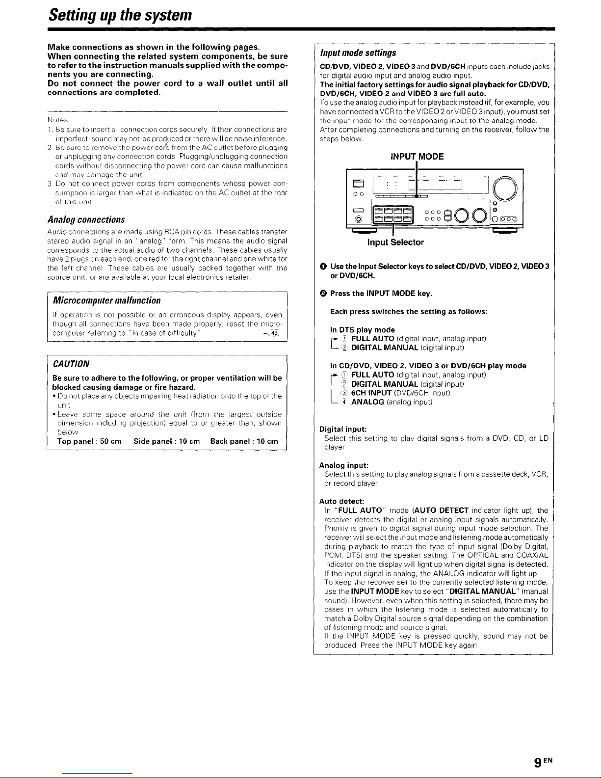
Input
mode
settings
CD/DVD, VIDEO2,VIDEO 3
for digital audio input
The initial factory settings for audio signal playbackfor CD/DVD,
DVD/6CH, VIDEO 2 and VIDEO 3 are full auto.
To
use the analog audio inputfor playback instead (if, forexample, you
have connected a
the input mode for the corresponding input to the analog mode.
After completing connections and turningonthe receiver, followthe
steps below.
VCR
EI
I~====::;-I
00
and
and
tothe VIDEO 2or VIDEO 3input), you
INPUT MODE
DVD/6CH inputs each include jacks
analog audio input.
~J
0
must
set
o
@ E:lE:lE:lE:l
=
1"'''''';''''''1
t---=--
Input Selector
o Use the Input Selector
or
DVD/6CH.
fJ)
Press the INPUT MODE key.
Each
press switches
In
DTS play mode
I FULL AUTO (digital input. analog input)
C
:g.
DIGITAL
MANUAL
~~~soo
keys
to select CD/DVD,VIDEO2,VIDEO 3
the
setting as follows:
(digital Input)
~(QQ9
~
CAUTION
Be
sure to adhere to
blocked causing damageorfire hazard,
• Do not place any objects impairing heat radiation onto the top of the
unit
• Leave some space around the unit (from the largest outside
dimension including projection) equal toorgreater than, shown
below
Top
panel:50cm
the
following.orproper ventilation will be
Side
panel:10cm
Back
panel:
10 cm
In
CD/DVD, VIDEO2,VIDEO 3 or DVD/6CH play mode
r
FULL AUTO (digital input, analog input)
:,g
DIGITAL
@
6CH
[
.
~.
ANALOG (analog input)
Digital input:
Select this setting to play digital signals from a
player
Analog input:
Select this setting to play analog signals fromacassette deck,
or
record player
Auto detect:
In
"FULL AUTO" mode (AUTO DETECT indicator light
receiver detects the digital or analog input signals automatically.
Priorityisgiven to digital signal during input mode selection. The
receiver will select theinput mode
during playback to match the type of input signal (Dolby Digital,
PCM,
DTS)
indicatoronthe displaywill lightupwhen digital signalisdetected.
If the input signalisanalog, the ANALOG indicator will light
To
keep the receiver settothe currently selected listening mode,
use the INPUT MODE key to select "DIGITAL MANUAL" (manual
sound). However, even when this settingisselected, there may
casesinwhich the listening modeISselected automatically to
match a Dolby Digital source signal dependingonthe combination
of
listening mode and source signal.
If the INPUT MODE keyispressed quickly, sound may not
produced Press the INPUT MODE key again
MANUAL
INPUT (DVD/6CH input)
and the speaker setting.
(digital input)
and
DVD,
CD,orLD
up),
listening mode automatically
The
OPTICAL
and
COAXIAL
VCR,
the
up.
be
be
Settingupthe
system
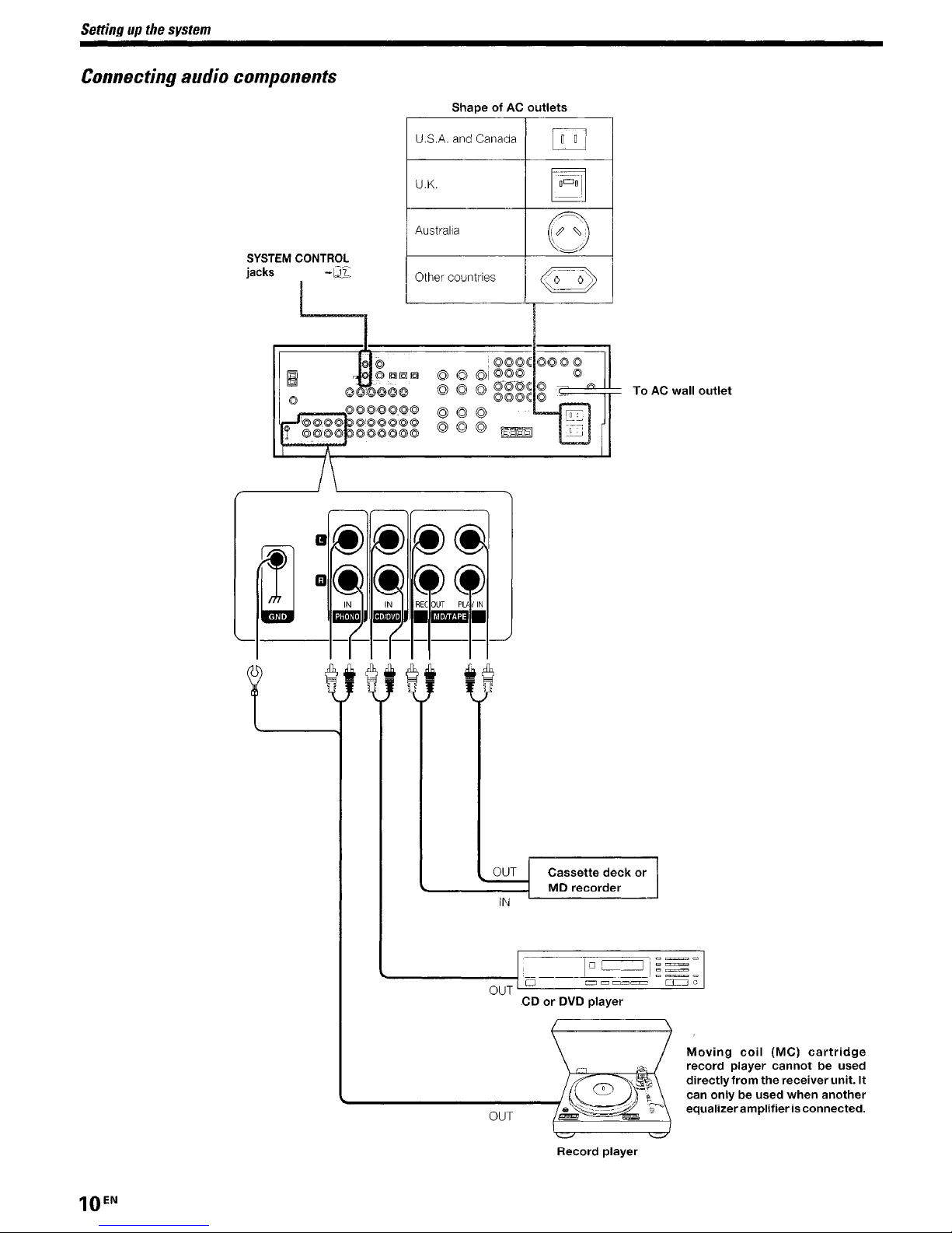
Connecting
audio
components
SYSTEM
jacks
CONTROL
-Wl:
I
I
~i1©
o
[I
©
'O'i©©©~~~'©©©©©
" ©(i)'©©
A
1\
©1QJ1!lJ~
OOO@(OO
©©©@©.@©
©©©©©©
ShapeofAC
U.S.A. and Canada
U.K.
Australia
Other countries
.
©J©J
©J©J©J
©J©J©J
©J©J©J
l©>©©
©JI@@@
©"©-«:l\
@©@
~
outlets
l\:©@@@
,,@
l\:
OJ]
~
(~
~:
\ .
.''-......-.-''/
G
~o--o>
"---~
©
©--
=
[G
,~riJ
r
ToACwall
outlet
IJ
m
~
@
@
(j) (j)
IN IN
BE
ID!I!J
@
@
mrm.
~,
----
1--""
OUT
IN
Cassette
MD
recorder
deck
or
EN
10
OUT
.CDorDVD
Record
player
player
Moving
record
directly
can
onlybeused
equalizer
coil
(MC)
player
from
amplifierisconnected.
cartridge
cannotbeused
the
receiver
when
unit.
another
It
Settingupthe
system
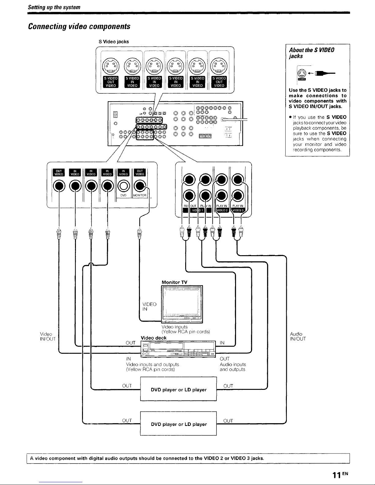
Connecting
;;;;©;
video
components
S Video
jacks
r I
I©)
I.
©)1©)i©)l©)
"
EIIliiJ
.•
mf!I' · • · • · • · •
DVD
MONITOR
r--l
•••
I_
(~-ir
',
I(j)
©)
•••
(j)11~
'.
@!
About the S
jacks
12-'·-~
I
Use
the
make
video
S VIDEO
• If you
jacks
playback components,
sure to use the S VIDEO
Jacks
your monitor
recording components.
VIDEO
S VIDEO
connections
components
use
toconnectyour video
when connecting
IN/OUT
the S VIDEO
and
jacks
with
jacks.
video
to
to
be
'--
Video
IN/OUT
--
--
---1-------1--'
~"OUT
~~'"N
••••
'-
- - - - -
i
~
'PLAy:.~~1
loU
~
--
-1--'
t;i
V
-------
,-1-
......
_I
Monitor
VIDEO
IN
Video inputs
(Yellow
Video
-...;;O..;,U.;.,T-II
IN
Video Inputs and outputs
(Yellow
It;j
pili
00
RCA
deck
pin cords)
TV
~.-._=~~:-._.:?::.:_-~--
=
RCA
II
pin
~
l
cords)
IN
OUT
Audio inputs
and outputs
Audio
IN/OUT
OUT
OUT
Eeo
component
with
digital
audio
outputs
DVD
playerorLD
DVD playerorLD
shouldbeconnectedtothe
player
player
OUT
OUT
VIDEO 2orVIDEO 3 jacks.
Seuingupthe
system
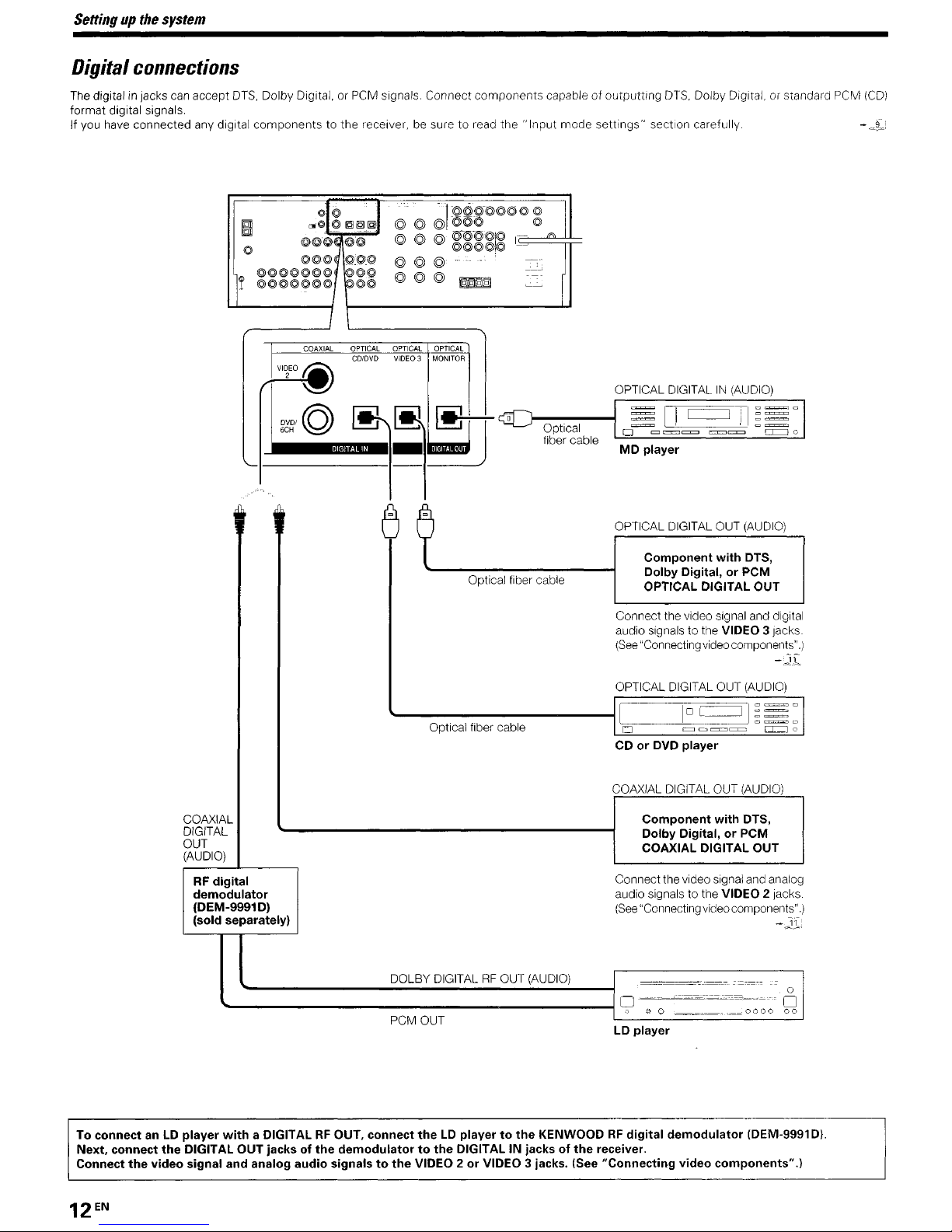
Digftalconnec#ons
The digitalinjacks can accept DTS, Dolby Digital, or PCM signals. Connect
format digital signals.
If you have connected any digital
components
to the receiver, be suretoread
components
the"
capableofoutputting
Input
mode
settings"
DTS, Dolby Digital, or standard PCM
section carefully. -
(CD)
c~i:
I
0
~~~©~©©
©©©©©©©
r
VIDEO~
/--L..;
DVDI©
6CH
~~lg
~§§J
©lO"~O@
©©©
©©.©
g~~
o©©
I
COAXIAL
OPTICAL
CD/DVD
~
@ @ @©©© ©
@ @ @
@@@
@@
OPTICAL
VIDE03
~
]@©i@@@@
(g©T©gj©
@@@o@
....
_-
©
~
OPTICAL
MONITOR
~JI<C
~
©
I "'"
._.
--,
---
~~
-'
Optical fiber cable
Optical
fiber ca
OPTICAL DIGITALIN(AUDIO)
---II
ble
=[I c::=:=J J I
,0
c:::::lc:=:.:J~
MD player
OPTICAL DIGITAL OUT (AUDIO)
Component with DTS,
Dolby Digital, or PCM
OPTICAL DIGITAL OUT
Connect the video signal and digital
audio signals
(See
"Connecting videocomponents".J
~~
to
the VIDEO 3jacks.
~~~
c:r:::::::::::Jo,
I
-;J,i
OPTICAL DIGITAL OUT (AUDIO)
----------l[
COAXIAL
DIGITAL
OUT
(AUDIO)
RF
digital
demodulator
(DEM-9991
(sold separately)
Optical fiber cable
D)
DOLBY DIGITALRFOUT (AUDIO)
'=0=-----'-=-=--==
CD or DVD player
COAXIAL DIGITAL OUT (AUDIO)
Connectthevideo signal andanalog
audio signals
(See
o
------------------------~,
To connect
Next. connect the DIGITAL OUT jacks of the demodulator to the DIGITAL IN jacks of the receiver,
Connect the video signal and analog audio signalstothe VIDEO 2orVIDEO 3 jacks, (See "Connecting video components".)
anLDplayer
with
a DIGITALRFOUT, connect theLDplayer to the KENWOODRFdigital demodulator IDEM-9991Dl.
PCM OUT
LD player
1°
[
~~==~
= 0
Component with DTS,
Dolby Digital, or PCM
COAXIAL DIGITAL OUT
to
"Connecting videocomponents".)
.~~-===,,::c-,""~~~""=._._
0 0
the VIDEO 2 jacks.
-),1.;
0
~.__~.,_~oooo
00
o
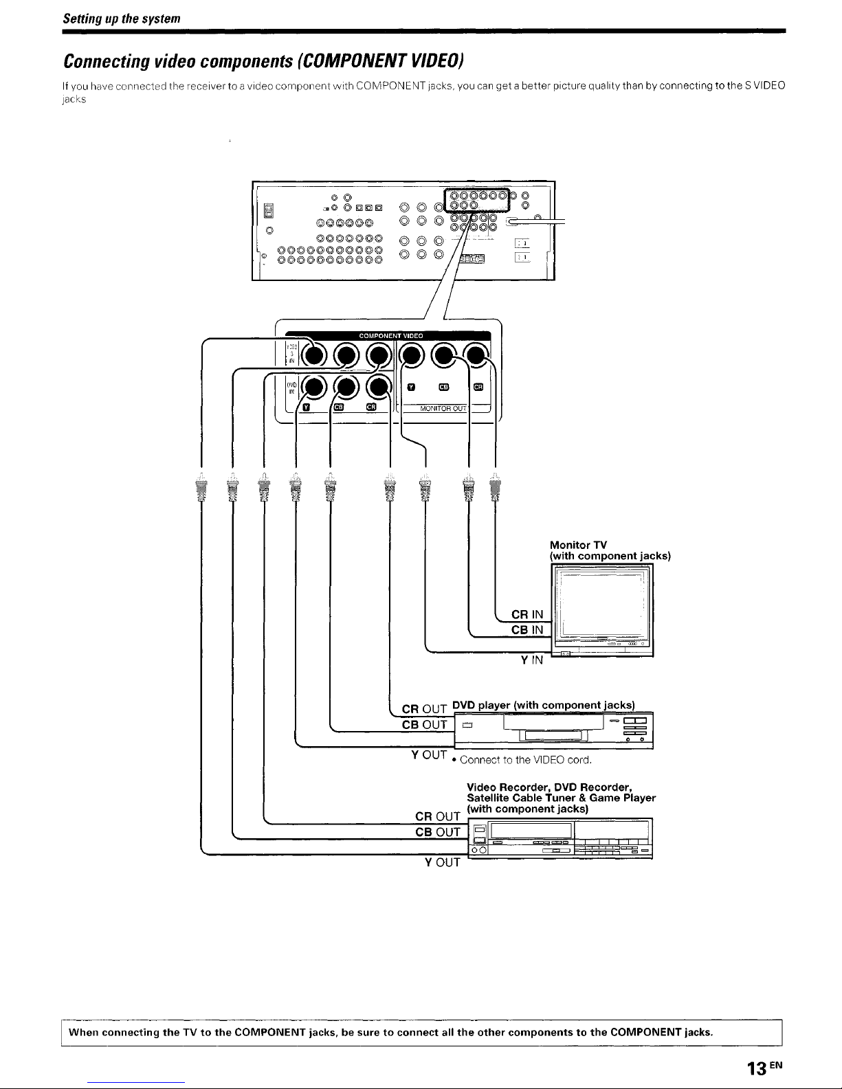
Settingupthe
system
Connecting
If you have connected the receiver to avideo component
jacks
video
components
(COMPONENT
©©©©©©
©©©©@©©
©©©©©©@©©©©
o ©©©@©©©©©©©
VIDEO)
with
COMPONENT jacks. you
can
get abetter picturequality than byconnectingtothe S VIDEO
CR
OUT
----......;;;=-;;;....;."'"--i
CBOUT
Y
OUT
CR
CB
YOUT
DVD
player
10
• Connect to the
Video
Satellite
OUT
(with
OUT
§ =
00
Monitor
(with
component
YIN
(with
component
I I
I I
VIDEO
cord.
Recorder,
component
Cable
Tuner&Game
c=.
DVD
jacks)
<=>"
=
TV
jacks)
Recorder,
jacks)
~
~
Player
,
When
connecting
theTVto
the
COMPONENT jacks,besuretoconnect
all
the
other
componentstothe
COMPONENT jacks.
Setting
lip
the
system
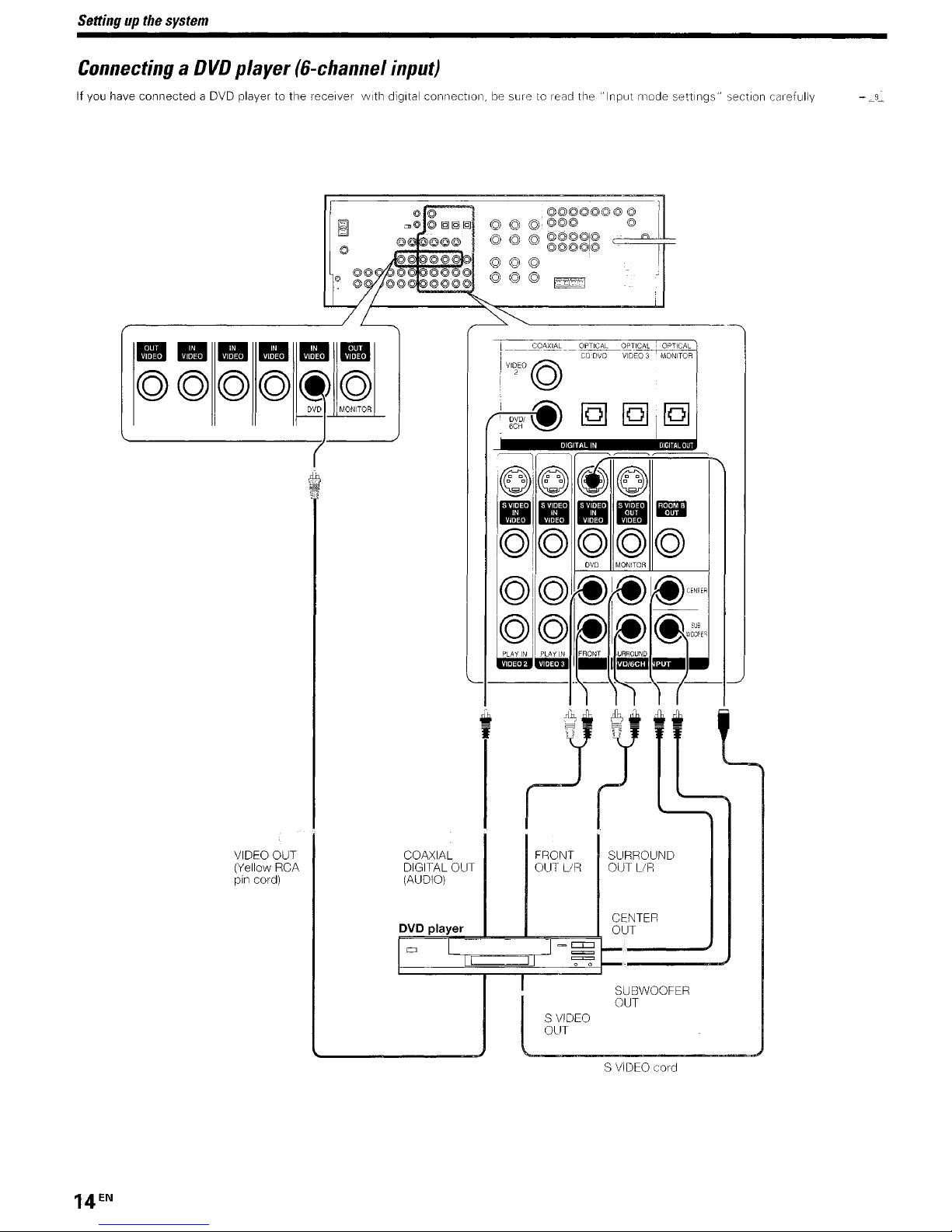
ConnectingaOVO
If you have connected a DVD playertothe receiver
player
(6-channel
input)
with
digital connection,besuretoread the
___
~AXIA~__.~~~~CV~L
VI~EO©
,~
6CH
--:::=:If
I©II©~©
1.1
'B'B'
IB
Icg),©©©©
"Input
~
!
[Q]
• ' 0
....
ovo
mode
~\~t-;
[Q],
I
~
,
IiI1iliI
-
MONITOR
settings"
~~~
[Q]
section carefully
-~9~
VIDEO OUT
(Yellow RCA
pin cord)
COAXIAL
DIGITAL OUT
(AUDIO)
©I'©I@~I~CENT"
©I©
~,,!ji;i
~
~I~
FRONT
.,
_IElIEIIJ_
..
_.
FRONT SURROUND
OUT
UR
S
VIDEO
OUT
~lI:;;E'
.l.JRROUND
----1--'
OUT LlR
SUBWOOFER
OUT
11_
S
VIDEO
cord
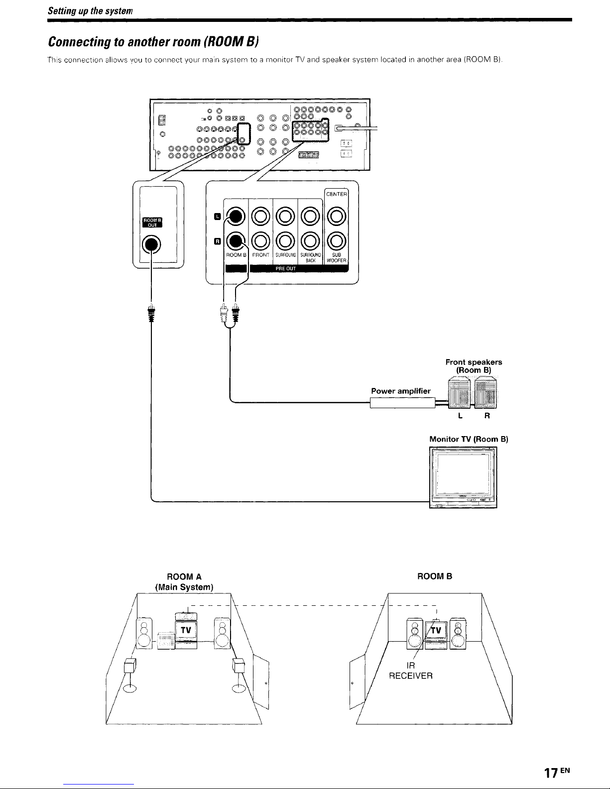
Settingupthe
system
Connectingtoanother
This connection allows you to connect your main system to a monitorTVand
room
(ROOM
,..----.----......,------,--
B)
m@©©©©
m@©©©©
ROOM B FRONT
SURBOUNO
SURROUND
BACK
-1-----
speaker system locatedinanother
CENTER
1
SUB
WOOfER
area
(ROOM
B).
ROOM A
(Main System)
Power amplifier
ROOMB
Front speakers
Monitor TV (Room
(Room
L R
B)
B)
17
EN
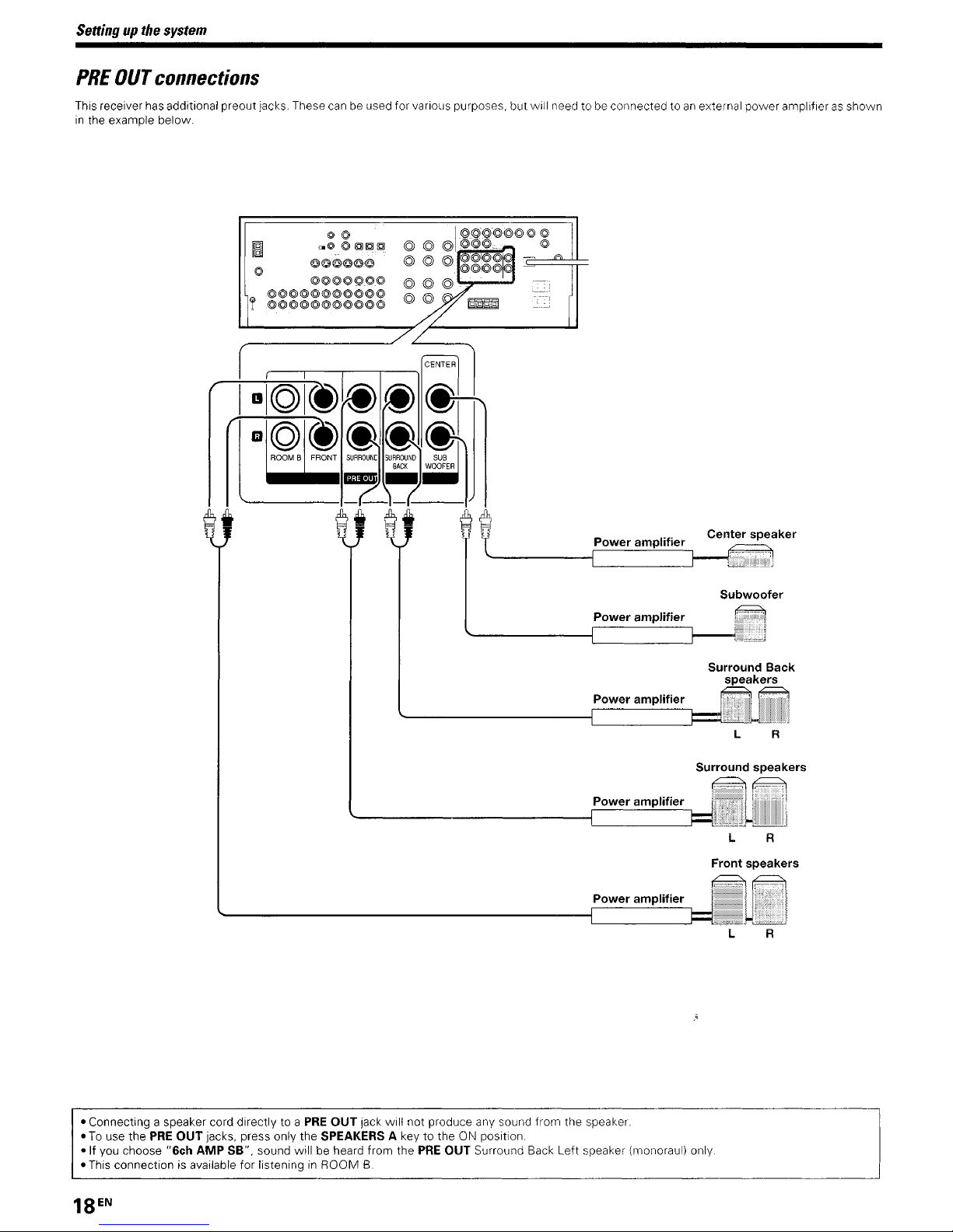
Settingupthe
PRE
OUT
This receiver has additional preout jacks.These can be usedfor various purposes,
in
the example
system
connections
below.
!@@@@@@@@@@@
o©
~O
©
IQJIQIIQI
.,_
•••
©©©o©©
@©@@©!.iPl@
@@@@@@@@@@@
@@
0'_
@@
@@
@@
but
will need to be connected toanexternal
power
amplifierasshown
Power amplifier
Power amplifier
Power amplifier
Power amplifier
Power amplifier
Center speaker
Subwoofer
Surround Back
speakers
L R
Surround speakers
L R
Front speakers
L R
- Connecting a speaker cord directly to a
- To use
-If
- This connection is available for listening in
the
PRE
OUT
you choose "6ch AMP SB", sound
jacks, press only the SPEAKERS A keytothe ON position.
PRE
will
be heard
OUT
ROOM
Jack
will not produce any sound
from
the
PRE
B.
OUT Surround Back
from
Left
the speaker.
speaker (monoraul) only.
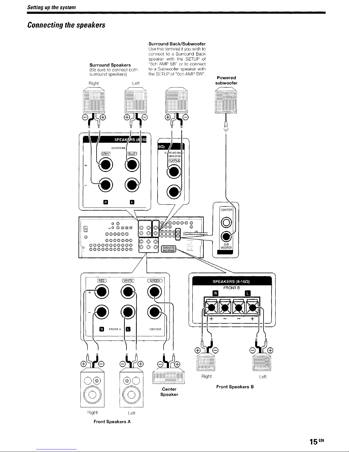
Settingupthe
system
Connecting
the
speakers
Surround Speakers
(Be
sure to connect both
surround speakers)
Right
.~,
Surround Back/Subwoofer
Use this terminalityou wish to
connect to a Surround Back
speaker with the SETUP of
"6cll AMP SB" or to connect
to a Subwoofer speaker with
the SETUP of "6ch AMP SW".
Left
Powered
5ubwoofer
@©
",0
©
~~~
©©©©©©
©©©©©©©
©©©©©©©©©©©
o ©©©©©©©©©©©
CENTER
SUB
WOOFER
SPEAKERS
FRONT B
(8-160)
o®
@
Right
Front Speakers A
®o
@
Left
Center
Speaker
Right Left
Front Speakers B

Settingupthe
system
Connecting
~~-.~.:,..,
.....
~,)-..:.:-.";:;..
o Strip coating.
CS#b0-
e Insert.
o Strip coating.
~o-
e Insert the cord.
the
terminals
".'
~
$ Loosen.
o Secure.
$ Push the lever.
o Return
~
~
the
lever.
Speaker
Front speakers Place at the front left and fight of the listening
position. Front speakers are required for
Center speaker: Place front
sound image
playback
Surround
behind. the listening positionateven heights. approximately 1meter
above the ears of the listeners. These speakers recreate sound
motion
Subwoofer : Reproduces powerful deep bass sounds
Surround back speakers. Place the surround back left and fight
speakers behind the listening position at the same heightasthe side
surround speakers
placement
:'~,
--_
..
_--
..
'
'~g~
r A
/1
I
\,a
f'~U.(,~.:\c=J
L\J
"X
/ \ position
I Surround
/ speakers
i (L,R)
____
i.
and
I
' /
j
Front speakers
(L,R) . Listening \
and
helps recreate sound motion Required for surround
speakers'
atmosphere Required for surround playback
~~"k"I'"
".
'\
*
--'>...L...__
~
Place at the direct left and right.orslightly
....
TV
I
--=--'--
Subwoofer \ \
and
--
~.o;\
center This speaker stabilizes the
----J
·\
".
it:
l
~
\.
L~_,..,
t-·-Surround
back speakers\
__-.J§§U.§_1?£11
all
surround modes
\.
'1
,--,
,.
\
_
Connectionofbanana
GS"U"~
- Sound will not be heard if the speaker terminalisnot fully secured
- Never short circuit the +
-If
the left and rightspeakers
cords are connected
unnatural
speakers correctly
Speaker
After confirming the speaker impedance indications printed on the
rear panelofthe receiver, connect speakers
ance ratings. Using speakers
indicatedon the rear panelofthe receiver could resultinmalfunctions
or damage to the speakers or receiver.
with
impedance
plugs
(For
the
U.S.A.
and
Canada)
&;v
and
- speaker cords
are
with
ambiguousacoustic imaging.Besure to connect the
connected inverselyorthe speaker
reversed polarity, the sound will
with
with
arated impedance other than that
matching imped-
- Although the ideal surround system consistsofall
listed above, if you
can divide those signals between the available speakers in the
speaker settings steps to obtain the best possible surround reproduction from the speakers you have available -
Channel
(Except
The space between radio channels has been set to the one that
prevailsinthe area to which the systemisshipped However, if the
be
current channel space setting does not match the settinginthe
where the systemistobeused, for instance when you move trom
area
receptionofAM/FM
change the channel space setting in accordance
referring to the following table.
space
for
the
1 or area 2 showninthe following table or vice versa, proper
U.S.A,
1
American countries
2 Other countries
7Sus
AUIIl<Hz
Fl.ll00<Hz
. "
11III
don't
have a center speaker or asubwoofer, you
switching
U.S.A.,
Canada,
U,K.,
and
Australia)
broadcasts cannot be expectedInthis case.
Area
Canada and South
SOus
AM!ll<Hz
FM5Il<Hz
I
j
[]j]
L-----
r--
If!
IT
!
Space Frequency
FM. 100 kHz
AM:10kHz
FM. 50 kHz
AM
_
..
,l)
~©~oo©
@@@@@@
@@o@o@@@@@@o
@@@@o@@@@@@@ '"
with
CHANNEL
9 kHz
e@
@1Ql1i:il1<il
the speakers
2:1.
----
area
your area by
-
~
©
©
'i:
@<!.:
© I('
Turn the power
switch level. Move switch lever to match your
screwdriver or other pointed tool. then turn the power
OFF
by pressing the POWER key before moving the
area
With a small
all
again.
 Loading...