

Kenwood KRC-791 Service Manual
CASSETTE RECEIVER
KRC-791/Y
SERVICE MANUAL
© 2001-11 PRINTED IN JAPAN
B51-7859-00 (S) 1929
The CASSETTE MECHANISM OPERATION DESCRIPTION is the same model D40-1122-05.
Please refer to the service manual for model D40-1122-05(B51-7542-00).
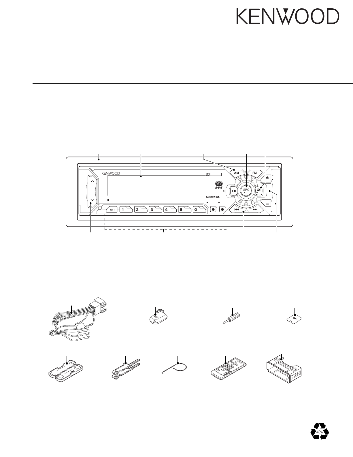
Panel assy
(A64-2577-02)
DC cord
(E30-4942-05)
50Wx4
Knob(VOL)
(K25-1404-03)
Front glass
(B10-4156-01)
KRC-791
B NRLOUD SCAN B.S/RDM REP
Knob(1-6)
(K25-1405-02)
Remote controller assy
(A70-0886-15)
Knob(FM,AM)
(K25-1406-03)
DOLBY B NR
PROG/PTY
MTL/M.RDM
TI
VOL ADJ
Knob(SRC)
(K24-3835-04)
EX
DISP
NAME.S
OFF AUD
Knob(UP,DW)
(K25-1408-03)
Antenna adaptor
(T90-0523-05)
Knob(PROG)
(K25-1407-03)
DAB
ANG
CLK
MENU
Front glass
(B10-4222-03)
Screw set
(N99-1704-05)
Plastic cabinet assy
(A02-1497-13)
Lever
(D10-4562-04)x2
MASK-key
T
orsion coil spring
(G01-2924-04)
Remote controller assy
(A70-2025-05)
Mounting hardware assy
(J21-9716-03)
2
ILL
TEL MUTE
ACC
ANT CON
P CON
BACK UP
EXT AMP CONT
FM+B
BUFFER
BUFFER
DECODER
RDS
IC11
IC2
E-VOL
MPX
N.C.
AM+B
SYSTEM u-COM
IC1
KEY
MATRIX
RESET
SW
LCD
DRIVER
REMO
G/R SW
RESET
IC15
MOTHER u-COM LCD TYPE
IC1
DRIVER
SUB MOT
IC13
MAIN MOT
AVR
SUB MOT
AVR
ILL AVR
A 8V
IC3
SW14V
EXT AMP CONT
DIMMER
ACC DET
TEL MUTE
P CON
B.U DET
ANT CON
SW5V B.U.5V
P-5V
Q21,22
SRM
MECH
POWER IC
THERMO
PROTECT
IC4
IC10
MUTE LOGIC
DRIVER
MUTE
Q1-4
SP OUT
1.8V PRE OUT
LCD
ANT.
DET
SRM MECH
IC2
Q39
Q32
Q45
Q25
Q26,27
Q28-31
Q24
Q23
Q36
Q33,34
Q37,38
Q41,42
Q3,4
Q73
Q90
Q88
Q89
AUDIO
S-METER
IFC OUT
PLL DATA
PLL CLK
SW5V
FM
AM
TAPE
CHANGER
S METER
QUAL
SDA
SCK
S MUTE
A 8V
MODE 2
SUB-
MOT+B
SUB+
MODE 1
MS MODE
F/R
MUTE
MTL ON/OFF
BOLBY B/C
DOLBY ON/OFF
MS OUT
R REEL
F REEL
MODE 3
TAPE IN
SRM SW2
SRM SW1
RCLK
QUAL
RDATA
NOISE
S METER
IFC
IFC OUT
PLL DATA
PLL CLK
MS OUT
MTL ON/OFF
MODE 2
MODE 3
R REEL
MODE 1
F REEL
MS MODE
F/R
MUTE
DOLBY ON/OFF
DATA C
CH RST
CH MUTE
DOLBY B/C
DATA H
CH CON
CH CLK
REQ H
REQ C
TAPE IN
SRM DET
RESET
SUB MOT2
SUB MOT1
SUB MOT3
CASS/SRM
MOTOR
ILL ON
AM+B
FM+B
SCK
SDA
PRE MUTE
MUTE
BEEP
P MUTE
ACC DET
PHONE
DIMMER
EXT AMP CONT
P CON
P-5V
P ON
ANT CONT
B.U DET
SW5V
SW5V
3
3
13
CH MUTE
CH RST
DATA H
DATA C
CH CON
REQ C
CH CLK
REQ H
BACK UP
8
1200mV
388mV
A 8V
SW5V
PANEL5V
2
B.U.5V
4
2
SUB+
SUB-
2
SUB-
SUB+
MOT+B
A8V
PAN5V
B.U.5VSW5V
MUTE
AC GND
BACK UP
SW5V
B.U.5V
B.U.5V
CH
FM
1800mVTAPE
AM
3600mV
855mV
1372mV
600mV
3600mV
1800mV
E TYPE K TYPE
1800mV
SW5V
245mV(ETYPE)
460mV(KTYPE)
FM:
AM:
170mV
TUNER
CASSETTE MECHA
CD-CHANGER
MD-CHANGER
(X16-154X-XX)
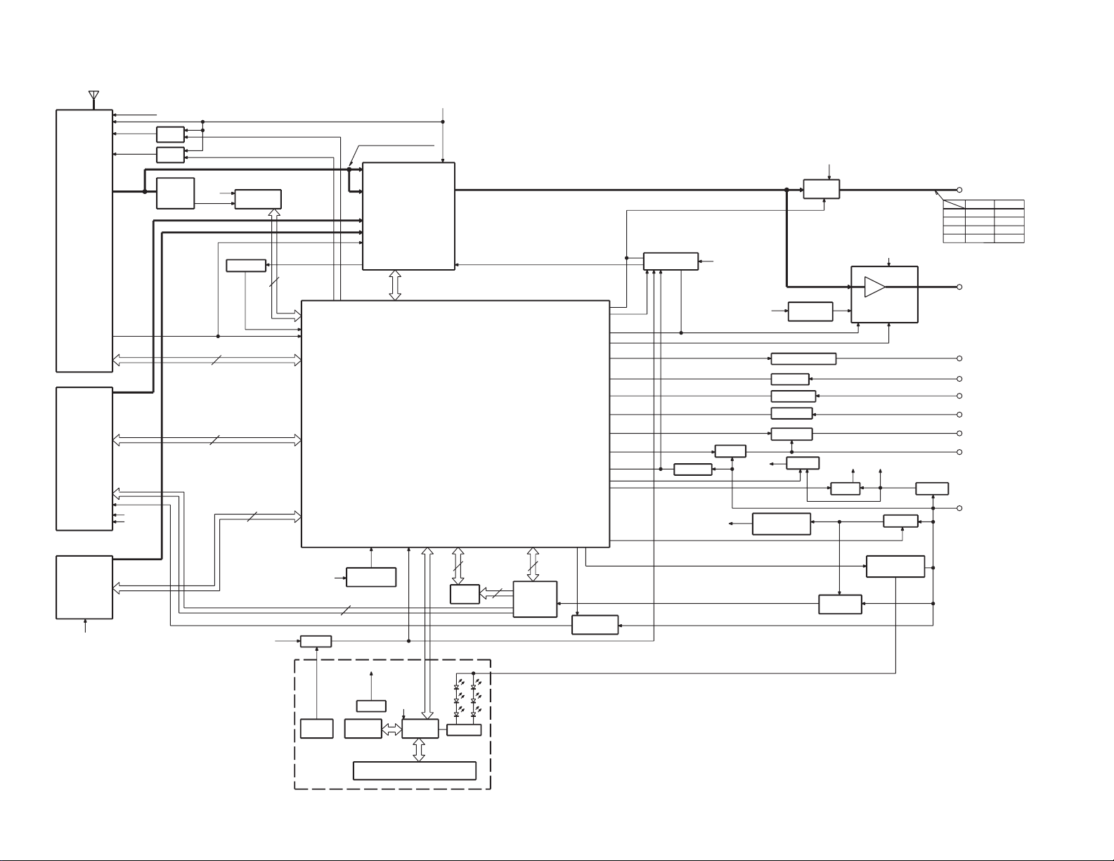
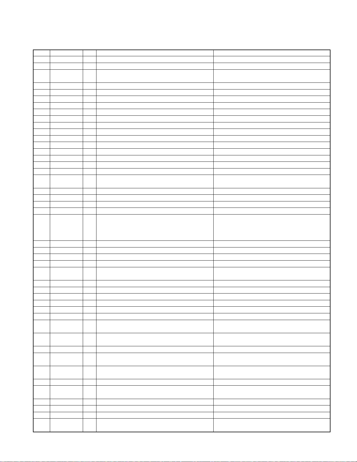
KRC-791/Y
BLOCK DIAGRAM
KRC-791/Y
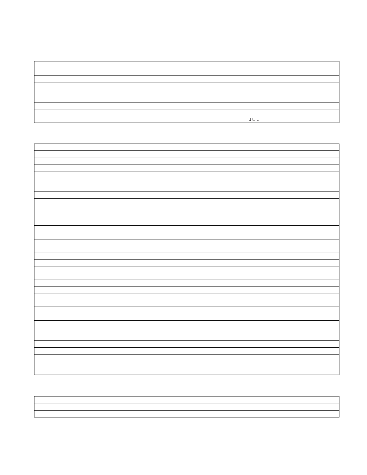
COMPONENT DESCRIPTION
● SWITCH UNIT(X16-154X-XX) (X16-189X-XX)
Component
IC1 LCD DRIVER with Key Matrix
IC2 Remote Control IC
Q1 Key Detection SW Q2 starts key scan in M&T.
Q3,4 Key Illumination SW
Q5
Q6
Q7 Dimmer SW The base of Q7 is normally "H" but becomes "
● SYNTHESIZER UNIT(X14-6442-7X) (X14-6452-XX)
Component
IC1 System µ-com
IC2 E-VOL, N.C, MPX
IC3 Regulator IC for Audio 8V
IC4 Power IC
IC10 Mute logic IC
IC11 RDS decoder
IC13 Motor driver IC
IC15 Reset IC
Q1~4 PRE OUT MUTE SW Pre outs are muted when the base goes "H".
Q18~20 Audio 8V AVR
Q21, 22 B.U 5V AVR
Q23 SW 5V ON when the base goes "L".
Q24 B.U detection ON when the base goes "H" during B.U applied.
Q25 ACC detection ON when the base goes "H" during ACC applied.
Q28~31 P-CON SW Q28 is turned ON when Q31's base goes "H".
Q32 Dimmer SW ON when the base goes "H" while vehicle small lamps turn on.
Q33,34,44
Q36 SW 14V ON when base goes "H".
Q37,38 Motor driver supply Q38 is turned ON when Q37's base goes "H".
Q39 External Amp Control ON when the base goes "L".
Q41, 42
Q43 Motor driver's voltage SW
Q45,46 Panel 5V SW Q45 is turned ON when Q46's base goes "H".
Q71 Pre out mute driver ON when the base goes "L".
Q72 E-VOL Mute SW ON when the base goes "H".
Q73 Noise buffer
Q85 IFC out buffer
Q86,88 AM+B SW Q88 is turned ON when Q86's base goes "H".
Q87,89 FM+B SW Q89 is turned ON when Q87's base goes "H".
Q90 Composite out buffer
Purpose • Function Operation • Conditions • Compatibility
Lights key illumination in Red when the base of Q3 is ON.
Lights key illumination in Green when the base of Q4 is "H"
VLCD Reference Voltage Supply
Remote Control IC Power Supply
Purpose • Function Operation • Conditions • Compatibility
Illumination AVR ON when Q44's base goes "H".
Cassette mecha main motor supply SW
Constant voltage circuit.
Activates remote control when the base of Q6 is "L".
Inverted darlington connection
Q20 is turned ON when Q18's base goes "H".
Inverted darlington connection
Q22 is turned ON when Q21's base goes "H".
Q42 is turned ON when Q41's base goes "H".
Base "H" ··· cassette mecha's submotor
Base "L" ··· mask mecha's motor.
" when DIMMER is ON.
● DOLBY UNIT(X87-3022-7X)
Component
IC1
Q1
Purpose • Function Operation • Conditions • Compatibility
Playback EQ, Dolby & Blank Detection
Constant Switching in Blank Detection
Switches the time constant according to the PLAY or FF/REW mode.
3
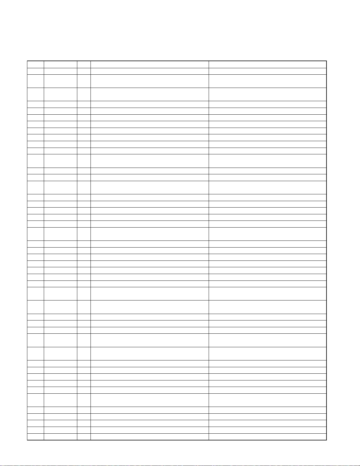
KRC-791/Y
MICROCOMPUTER'S TERMINAL DESCRIPTION
● UPD703033GC138 (IC1: X14-)
SYSTEM MICROCOMPUTER
Pin Name I/O Purpose Operation Description
1 AM+B O AM power supply terminal. During AM operation: H.
2 FM+B O FM power supply terminal.
3 AFS O Constant switching when noise is detected.
4 PLL-DATA I/O DATA input/output terminal from/to F/E.
5 PLL-CLK I/O CLOCK input/output terminal from/to F/E.
6 Evdd - Positive power supply terminal.
7 GND - Grounding terminal.
8 N.C O No connection.
9 BEEP O Beep output terminal.
10 REMO I Remote control input terminal.
11 P-ON O SW 14 V control terminal. Power ON: H. Power OFF: L.
12 P-STBY O Power IC STBY terminal control.
13 IC2-SDA I/O IC2 DATA line.
14 IC2-SCK O IC2 CLOCK line.
15 P-MUTE O Power IC muting terminal.
16 PRE-MUTE O Pre-Out muting terminal. During momentary power down: L.
17
D/A-SDA/DIM-CON
18 TEST - Test pin.
19 P-CON O Power control terminal. Power ON: H. Power OFF: L.
20 ANT-CON O Antenna control terminal. TUNER, TI ON: H
21 MUTE O Muting terminal.
22 N.C O No connection.
23 ACC-DET I Acc detection terminal. Acc detected: L. Acc not detected: H.
24 DIMMER I Small detection terminal. ON: L. OFF: H.
25 SW-5V O 5 V power supply terminal. ON: L. OFF: H.
26 CH-MUTE I Muting request from CH. ON: H. OFF: L.
27 CH-CON O CH control output. ON: H. OFF: L.
28 CH-REQH O Request output to CH. Requested: L.
29 CH-RST O Reset output to CH.
30
EXT-AMP-CONT
31 RESET I Reset input terminal Normal: H. Reset: L.
32 XT1 I Sub-clock connection terminal. The clock count is active even when Power is OFF.
33 XT2 - Sub-clock connection terminal.
34 REGC -
35 X2 - Main clock connection terminal.
36 X1 I Main clock connection terminal.
37 Vss - Grounding terminal.
38 Vdd - Positive power supply terminal.
39 CLKOUT O Internal System Clock output.
40 N.C O No connection.
41 MOTOR O Cassette mechanism main motor output terminal.
42 MODE3 I Cassette mechanism mode detection terminal.
43 MODE1 I Cassette mechanism mode detection terminal.
44 MODE2 I Cassette mechanism mode detection terminal.
45 N.C O Outputs Low. No connection.
46 SUB1 O Sub-motor output terminal (1).
O D/A data line. (V-LED)
O External amplifier control terminal (In 200 ms).
During FM operation: H.
Last FM with RDS model: H
During FM seek or AM search: L.
During reception: H.
Power IC OFF: L. Power IC ON: H.
During reset: Input.
Power OFF: L. All OFF: L.
During TEL muting: L.
ON: Open. OFF: L.
The time constant is 0.48 ms with all models.
Normal: L. When the system is reset, turns H then
L in 400 ms after recovery from reset.
L 40 ms: Bass boost OFF. L 70 ms: Bass boost LOW.
L 100 ms: Bass boost HIGH.
Output terminal for the capacitor in the regulator
in µ-COM.
Power ON: Oscillated.
Power OFF or momentary power down: Oscillation stopped.
When the motor is running: H.
When it is stopped: L.
4
KRC-791/Y
MICROCOMPUTER'S TERMINAL DESCRIPTION
Pin Name I/O Purpose Operation Description
47 SUB2 O Sub-motor output terminal (2).
48 SUB3 O Sub-motor output terminal (3).
49 CAS/SRM O
50 N.C O Outputs Low. No connection.
51 N.C O Outputs Low. No connection.
52 ILL-ON O FL +B output terminal. ON: H, OFF: L
53 PAN-5V O Panel 5 V control terminal. Panel detected: H Panel not detected: L
54 N.C O Outputs Low. No connection.
55 BVdd - Positive power supply terminal.
56 BVss - Grounding terminal.
57 TYPE1 I Destination type switching port.
58 TYPE0 I Destination type switching port.
59 N.C O Outputs Low. No connection.
60 N.C O Outputs Low. No connection.
61 ST TYPE1 I IC2 destination type terminal. Default: L.
62 ST TYPE0 I IC2 destination type terminal. Default: L.
63 SRM-SW1 I Panel position detection switch 1.
64 D/A-SDA O D/A clock line. (V-LED)
65 L CE I/O CE terminal for LCD driver.
66 SRM-SW3 I Panel position detection switch 3.
67 SRM-SW2 I Panel position detection switch 2.
68 FWD/REV O TAPE EQ input switching terminal. FWD: L. REW: H.
69 MS-CONT I/O
70 AVCONT O AD reference voltage control output. Same timing as P-ON. H during operation.
71 Avdd - Positive power supply terminal.
72 Avss - Grounding terminal.
73 Avref I
74 PHONE I PHONE detection terminal.
75 R-REEL I Cassette mechanism reel pulse input (REV). Vth = 2.5 V.
76 F-REEL I Cassette mechanism reel pulse input (FWD). Vth = 2.5 V.
77 N.C I No connection. Connected to GND.
78 SRM-DET I SRM mechanism detection. SRM mechanism detected: L.
79 NOISE I FM noise detection terminal. Model without RDS: Connected to GND.
80 S-METER I Signal meter detection terminal.
81 R-DATA I RDS decoder DATA input terminal.
82 R-QUAL I RDS decoder QUAL input terminal.
83 IFC-OUT I F/E IFC OUT input terminal. Station detected: L.
84 MUSIC I Music blank detection input.
85 PACK-DET I Cassette mechanism pack detection terminal. Cassette pack detected: L.
86 DOLBY O Dolby ON/OFF switching. ON: H. OFF: L.
87 R-CLK I RDS decoder CLK input terminal. Model without RDS and
88 CH-REQC I Request input from CH. ON: L.
89 KEY REQ I Communication request from LCD driver.
90 N.C I No connection. Connected to GND.
91 EQ-MUTE O EQ muting switching.
Cassette mechanism/SRM mechanism Cassette mechanism: H.
voltage switching terminal. SRM mechanism: L.
Panel detached: L.
Momentary power down: L.
During TAPE PLAY: H.
Constant switching terminal in case of blank During TAPE FF/REW or other than TAPE input: L.
detection. Cassette mechanism detected: L.
Cassette mechanism not detected: H.
Reference voltage supply terminal for A/D converter.
TEL MUTE: No more than 1 V.
NAVI MUTE:2.5 V or more.
Model without RDS and
RBDS: Connected to GND.
Model without RDS and
RBDS: Connected to GND.
Music signal detected: L.
Music signal not detected: H.
Cassette pack not detected: H.
RBDS: Connected to GND.
During TAPE PLAY: L. During TAPE FF/REW: H.
Other than TAPE input: H.
5
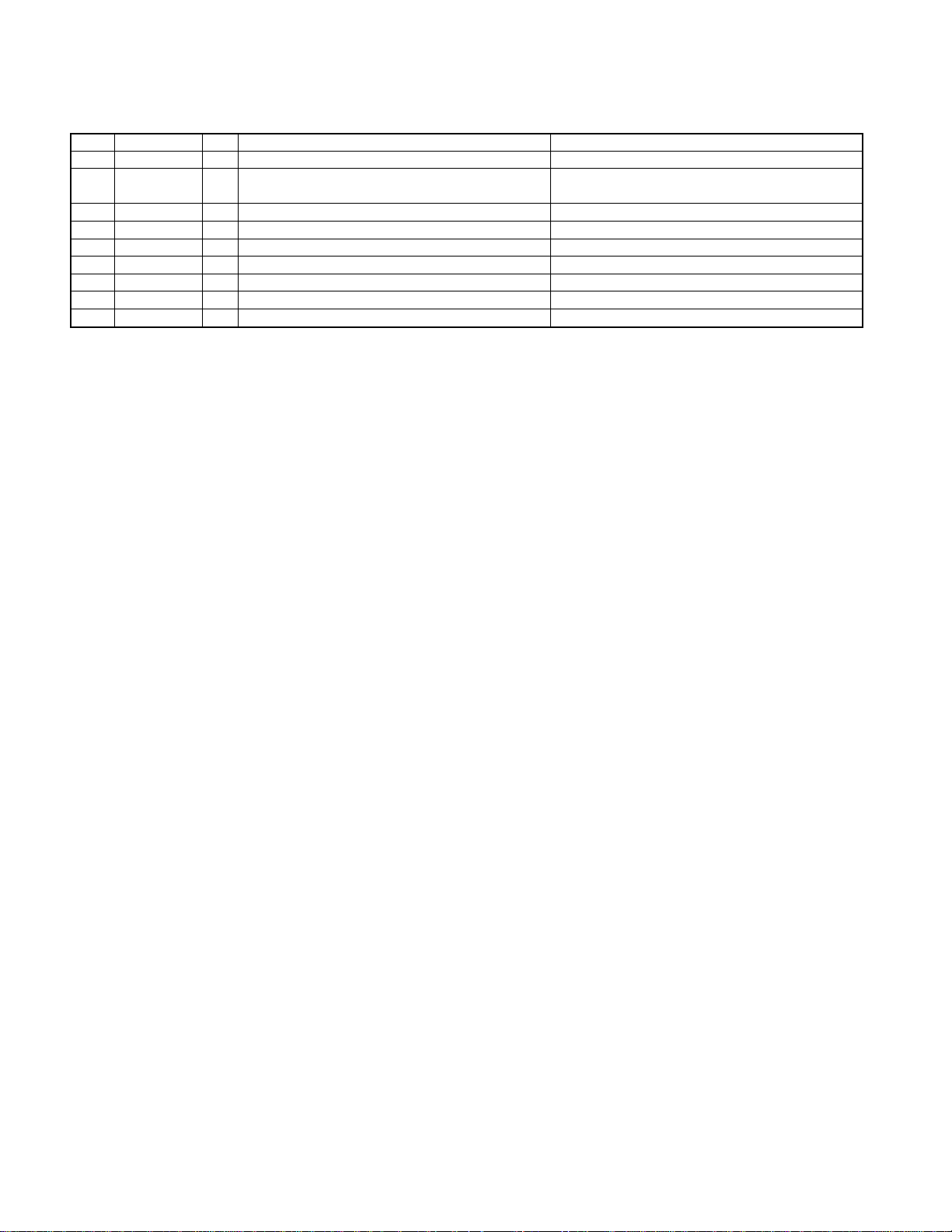
KRC-791/Y
MICROCOMPUTER'S TERMINAL DESCRIPTION
Pin Name I/O Purpose Operation Description
92 MTL O NORMAL/METAL switching. NORMAL: H. METAL: L.
93 BU-DET I Momentary power down detection terminal.
94 CH-DATAC I DATA input terminal from CH.
95 CH-DATAH O DATA output terminal to CH.
96 CH-CLK I/O CLOCK input/output terminal from/to CH.
97 L-DATA L I DATA line from LCD driver.
98 L-DATA S I/O DATA line to LCD driver.
99 L-CLK I/O CLK line to LCD driver. Panel detected: L
100 N.C O Outputs Low. No connection.
Back-Up detected: L
Back-Up not detected (momentary power down): H.
6

TEST MODE
M&T-SRT Model Test Mode
1. How to enter the test mode
• While holding the FM and Preset 6 keys, reset the unit.
2. How to exit from the test mode
• While holding the Preset 6 key, reset the unit.
• (Note) The test mode cannot terminated by Acc OFF,
power OFF or momentary power down.
3. Initial status in the test mode
• Sources: All OFF.
• Display: All segments are lit.
• Volume: -10 dB (displayed as 30)
• Loudness: OFF
• CRSC: OFF regardless of the presence of switching
function.
• SYSTEM Q: Flat.
• Blank Skip: OFF. (C/R model)
• LED: White for no scanning. (VLCD model)
KRC-791/Y
7. Audio-related specifications
• A short press of the Q key initiates the audio adjustment
mode.
• Pressing the ∗ key on the remote initiates the audio
adjustment mode.
• Continuous holding of a remote control key is inhibited.
• Bass, Middle and Treble are adjusted in 3 steps of Min/
Center/Max with the Track Up/Down keys.
• Balance is adjusted in 3 steps of Left Max/Center/Right
Max with the Track Up/Down keys.
• Fader is adjusted in 3 steps of Rear Max/Center/Front
Max with the Track Up/Down keys.
• HPF is adjusted in 2 steps of Through/220 Hz with the
Track Up/Down keys.
• LPF is adjusted in 2 steps of Through/120 Hz with the
Track Up/Down keys.
• Bass f, Bass Q, Bass EXT, Middle f, Middle Q and Treble
f are not dealt with by the audio adjustment.
4. Special display in Tuner mode
• When any of the following messages is displayed in Tuner
mode, the front end may be abnormal.
• "TNE 2P NG": The EEPROM is set to the default (unstable values) because the F/E was shipped without passing
through the adjustment process, etc.
• "TNCON NG": Communication with the F/E is not possible.
5. Forced switching of K3I
• Each press of the Preset 6 key in Tuner mode should
switch K3I from AUTO → Forced Wide → Forced Middle
→ Forced Narrow → AUTO. The initial status is AUTO
and the display shows these modes as follows.
• AUTO : FMA
• Forced Wide : FMW
• Forced Middle : FMM
• Forced Narrow : FMN
6. Test mode specifications of the CD receiver
• Forced ejection is inhibited in the reset start operation.
When the unit is reset while a CD is loaded in it, the CD
is not recognized by resetting.
• Each press of the Track Up key jumps to the following
track numbers.
No. 9 → No. 15 → No. 10 → No. 11 → No. 12 → No. 13 →
No. 14 → No. 9 (The cycle restarts from here.)
• Each press of the Track Down key jumps to the previous
track number to the track being played.
8. Menu-related specifications
• A short press of the CLK key initiates the Menu mode.
• Pressing the DNPP/SBF key on the remote initiates the
Menu mode.
• Continuous holding of a remote control key is inhibited.
• Calendar adjustment, calendar display switching and calendar memo are eliminated from the targets of continuous key holding. (FL model).
• In the color adjustment mode, pressing the Preset 1 key
sets Red, 2 sets Blue, 3 sets Green and 4 sets Green.
(VLCD model)
• Contrast is adjusted in 3 steps of 0/5/10 and the default
is 5. (VLCD/LCD model)
• Brightness is adjusted in 3 steps of 0/5/10 and the default
is 10. (Normal FL model)
9. Backup current measurement
• When the unit is reset while Acc is OFF (i.e. by turning
Back-Up ON), the MUTE terminal goes OFF in 2 seconds in place of 15 second. (The panel, CD mechanism
and TAPE mechanism are not activated at this time.)
7

KRC-791/Y
TEST MODE
10. Special display when the display is All ON
Pressing the Preset keys while the power is All OFF
displays the following information.
Version display
(8 digits, Month/Day/Hour/Minute)
PRESET1 (Display)
SYS xxxxxxxx System microcomputer
PAN xxxxxxxx Panel microcomputer
PRESET2
PRESET3 Long press/hold: Clear power ON time.
PRESET4
PRESET5 Long press/hold: Clear TAPE/CD/MD ejection
PRESET6 Long press/hold: Clear Panel open/close count.
Serial No. display (8 digits)
(Note) CD/R K type eXcelon model
(Display) SNo. xxxxxxxx
Short press: View power ON time.
(The All OFF period is not counted.)
(Display)
PonTim xxxxx Max. 65535 (hours)
Short press: Display TAPE/CD/
MD operation time.
Long press/hold: Clear TAPE/CD/MD operation
time. (Display)
CDTime xxxxx (CD/R)
TapTim xxxxx (C/R) Max. 65535 (hours)
Short press: Display TAPE/CD/
MD ejection count.
count. (Display)
EjeTim xxxxx Max. 65535 (times)
Short press: Display Panel open/close count.
(Display)
PnCnt xxxxx Max. 655350 (times)
11. Other specifications
• Automatic panel closing when a tape/CD is inserted is
inhibited. (M&T model)
• Panel operation by turning power OFF/ON is inhibited.
(M&T model)
• Pressing the ATT key opens or closes the panel. (M&T
model)
• Messages such as "CODE OFF" are not displayed when
power is turned ON.
• Pressing the TI (AUTO) key during changer operation
turns 2zone ON. 2zone can be turned OFF by pressing
the TI (AUTO) key again. The P/S dot lights while 2 zone
is ON.
• Pressing and holding the CLK key for a second in the All
OFF status the Mask Key (security) write mode.
■ Security-related information
• Forced Power ON mode (All models)
Even when the security (Mask key) is approved, resetting the unit while holding the ATT and Preset 4 keys
makes it possible to turn the power ON for 30 minutes.
After 30 minutes have elapsed, it is not possible to return
to the previous condition unless the unit is reset again.
• Method of registration of the security code after
EEPROM (Tuner Unit Ass'y) replacement (Code
security model)
1.Enter the test mode. (See 1 How to enter the test mode)
2. Press the CLK key to enter the security registration
mode.
3.Enter the code using the Preset 1/2/3/4 keys.
Example: To enter "3510"
• Press the Preset 1 key 4 times.
• Press the Preset 2 key 6 times.
• Press the Preset 3 key twice.
• Press the Preset 4 key once.
4.Press and hold the DISP key for 3 seconds until
"APPROVED" is displayed.
5.Exit from the test mode. (See 2 How to exit from the
test mode)
(Note) All Clear is not applicable to the security code
of this model.
• Simplified method of clearing the security code
(K Type only)
1.While the code entry is requested, press and hold the
VOL UP key for 3 seconds while holding the DISP key
pressed.(This should turn ---- off.)
2.Enter "KCAR" from the remote. (Same way as the 00
model)
Press the 5 key on the remote twice, then press the
Track Up key. (This enters "K")
Press the 2 key on the remote 3 times, then press the
Track Up key. (This enters "C")
Press the 2 key on the remote once, then press the
Track Up key. (This enters "A")
Press the 7 key on the remote twice, then press the
Track Up key. (This enters "R")
3.The security code is cleared and the unit enters the All
OFF mode.
4.If you commit a mistake in the code entry, the unit enters
the code request mode again.
8
 Loading...