

Page 1

KRC-235
KRC-225
CASSETTE RECEIVER
INSTRUCTION MANUAL
AMPLI-TUNER-LECTEUR DE CASSETTE
MODE D’EMPLOI
RADIO CASETE
MANUAL DE INSTRUCCIONES
RADIO CASSETE
MANUAL DE INSTRUÇÕES
Take the time to read through this instruction manual.
Familiarity with installation and operation procedures will help you obtain the best
performance from your new cassette-receiver.
For your records
Record the serial number, found on the back of the unit, in the spaces designated on the
warranty card, and in the space provided below. Refer to the model and serial numbers
whenever you call upon your KENWOOD dealer for information or service on the product.
Model KRC-235/225 Serial number
© B64-2101-00 (KW/KN)
Page 2

— 2 —
English
Contents
Safety precautions.................................................3
About Cassette tape ..............................................4
General features.....................................................5
Power
Selecting the Source
Volume
Att enuator
Loudness
ec4 (Sound Coordinate)
Audio Control
Swit ching Clock Display
Adjusting Clock
Theft Det errent Faceplate
Tuner features ........................................................8
Tuning Mode
Tuning
Station Preset M emory
Auto Mem ory Entry
Preset Tuning
CRSC (Clean Reception System Circuit)
Cassette player features......................................10
Playing Cassette Tapes
Fast Forwarding and Rewinding
Tuner Call
External disc control features .. ...........................11
Playing External Disc
Fast Forwarding and Reversing
Track Search
Album Search
Track/Album Repeat
Track Scan
Disc Scan
Random Play
M agazine Random Play
Accessories ..........................................................14
Installation Procedure..........................................14
Connecting Wires to Te rminals ...........................15
Installation ...........................................................16
Tr oub leshooting Guide.........................................18
Specifications ......................................................21
Page 3
— 3 —
To prevent injury or fire, take the
following precautions:
•Insert t he unit all the way in until it is f ully
locked in place. Otherw ise it may fall out of
place when jolt ed.
• W hen extending the ignition, battery, or
ground wires, make sure to use autom otivegrade wires or ot her wires with a 0.75mm
2
(AWG18) or more to prevent w ire
deterioration and damage to the wire
coating.
•To prevent a short circuit , never put or leave
any metallic objects (such as coins or metal
tools) inside the unit .
• If the unit starts to em it smoke or strange
smells, turn off the power imm ediately and
consult your Kenw ood dealer.
• Make sure not t o get your fingers caught
between t he faceplate and the unit.
• Be careful not to drop the unit or subject it to
strong shock.
The unit may break or crack because it
contains glass parts.
• Do not touch the liquid crystal fluid if t he
LCD is damaged or broken due to shock. The
liquid crystal fluid m ay be dangerous to your
health or even fatal.
If t he liquid crystal fluid from the LCD
contacts your body or clot hing, wash it off
w ith soap immediately.
2WARNING
To prevent damage to the machine,
take the following precautions:
• Make sure to ground t he unit to a negative
12V DC power supply.
• Do not open the top or bottom covers of the
unit.
• Do not install the unit in a spot exposed to
direct sunlight or excessive heat or humidity.
Also avoid places wit h too much dust or the
possibility of water splashing.
• Do not set the removed faceplate or the
faceplate case in areas exposed to direct
sunlight, excessive heat or hum idity. Also
avoid places wit h too much dust or the
possibility of water splashing.
•To prevent det erioration, do not touch the
terminals of the unit or faceplate w ith your
fingers.
• Do not subject the faceplate to excessive
shock, as it is a piece of precision
equipment .
• W hen replacing a fuse, only use a new one
w ith the prescribed rating. Using a fuse wit h
the wrong rating m ay cause your unit to
malfunct ion.
•To prevent a short circuit when replacing a
fuse, f irst disconnect the w iring harness.
• Do not place any object between the
faceplate and the unit.
• Do not use your own screws. Use only t he
screw s provided. If you use the wrong
screw s, you could damage the unit.
2CAUTION
IMPORTANT IN FORMATION
About the disc changer to be
connect ed:
To connect a disc changer having the "O-N"
sw itch to this unit, set the "O-N" sw itch to "N".
When you connect a model with no "O-N"
sw itch, the converter cord CA-DS100 available
as an option may be required. For details,
consult your Kenw ood dealer.
A disc changer doesn't work when it is
connected wit hout using these opt ions.
If a model wit h no "O-N" switch is connected,
some unavailable functions and inform ation
that cannot be displayed are generated.
Note t hat none of the KDC-C100, KDC-C302,
C205, C705, and non-Kenwood CD changers
can be connected.
You can damage both your unit and the CD
changer if you connect t hem incorrectly.
FCC WARNIN G
This equipment may generat e or use radio
frequency energy. Changes or modifications
to t his equipment may cause harmful
interf erence unless the modifications are
expressly approved in the instruct ion manual.
The user could lose the authority t o operate
this equipm ent if an unauthorized change or
modif ication is made.
Safety precautions
Page 4

— 4 —
English
• If you experience problems during
installation, consult your Kenw ood dealer.
• If the unit does not seem t o be working
right, t ry pressing the reset button f irst. If
that does not solve the problem, consult
your Kenwood dealer.
•Press the reset but ton if the Disc auto
changer fails to operate correctly. Normal
operatin should be restored.
• Characters in the LCD may become dif ficult
to read in tem peratures below 41 ˚F (5 ˚C).
• The illustrations of the display and the panel
appearing in this manual are examples used
to explain more clearly how the controls are
used. Therefore, w hat appears on the display
in the illust rations may differ from what
appears on the display on the actual
equipment , and some of the illustrations on
the display may represent som ething
impossible in actual operation.
NOTE
Cleaning the Faceplat e Terminals
If t he terminals on the unit or faceplate get
dirty, wipe them with a dry, sof t cloth.
Cleaning the Unit
If t he faceplate of this unit is st ained, wipe it
w ith a dry soft cloth such as a silicon cloth.
If t he faceplate is stained badly, wipe t he stain
off with a cloth moist ened with neutral
cleaner, t hen wipe neutral detergent of f.
Applying spray cleaner directly to t he unit may
affect its mechanical parts. Wiping t he
faceplate w ith a hard cloth or using a volatile
liquid such as thinner or alcohol may scratch
the surf ace or erases charact ers.
Safety precautions
Cleaning the tape head
When t here’s noise or the sound quality is bad
during tape play the tape head maybe dirty,
clean the tape head.
About Casset te tape
• If the tape is slack tighten it.
• If the cassette tape label is peeling off glue it
on again.
• Don’ t use deformed cassette t ape.
• Don’ t place cassette t ape on the dashboard
etc. where t he temperature is high.
• Don’ t use cassette t ape that’s 100 minutes
long or longer.
About Casset te t ape
Reset butt on
Page 5
Press th e [SRC] butt on.
Source required Display
Tuner "TUnE"
Tape "TAPE"
External disc (KRC-235 only) "DISC"
Standby (Illumination only mode) "OFF"
Selecting the Source
Tu rning ON th e Pow er
Press th e [SRC] butt on.
Tu rning OFF t he Pow er
Press th e [PWR OFF] butto n for at least 1 second .
Power
General features
— 5 —
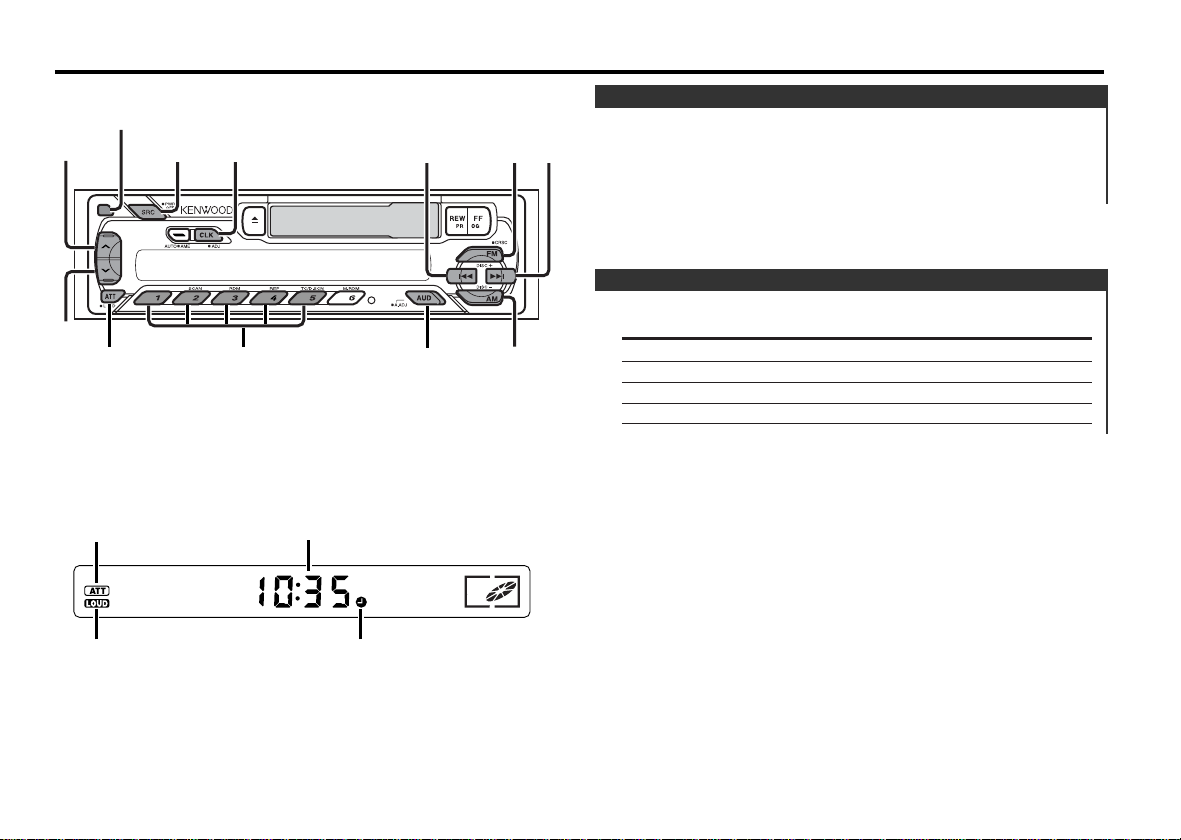
SRC/
PWR OFF
¢
4
CLK/
ADJ
FM
AM
AUD/
A.ADJ
ATT/
LOUD
d
u
#1 - 5
ATT indicator
LOUD indicator
Clock indicator
Clock display
Rel ease button
Page 6
1 Select the source for adjust ment
Press th e [SRC] butt on.
2 Enter Audio Control mode
Press th e [A.ADJ] butto n for at least 1 second.
3 Select the Audio it em for adjustment
Press th e [FM] or [A M] bu tton.
Each time t he button is pressed the item s that can be adjusted
sw itch as shown below.
4 Adjust the Audio it em
Press th e [4] or [ ¢] butt on.
Audio Control
2 Enter Control mode
Press th e [AUD] but ton.
3 Select the Sound t ype
Press th e [#1] — [#5] b utton .
Press button Sound setting Display
[#1] Flat "EC-1"
[#2] Rock "EC-2"
[#3] Pops/ Top 40 "EC-3"
[#4] Jazz "EC-4"
[#5] Easy "EC-5"
When t he ec4(Sound Coordinat e) setting is changed, the Bass and
Treble set in audio control replace the ec4(Sound Coordinat e) values.
4 Exit Control mode
Press th e [AUD] but ton.
You can recall the best sound set ting p reset for differ ent typ es of
th e music.
1 Select the source to set
Press th e [SRC] butt on.
ec4 (So und Coordinate)
Compen sating f or low an d hi gh ton es durin g low volume.
Press th e [LOUD] bu tton f or at least 1 secon d.
Each time t he button is pressed for at least 1 second the
Loudness turns ON or OFF.
When it ’s ON, "LOUD" indicator is ON.
Loudness
Turning t he volu me down quickly.
Press th e [ATT] b utton .
Each time t he button is pressed the Att enuator turns ON or OFF.
When it ’s ON, the "ATT" indicator blinks.
Attenuator
In creasi ng Vol ume
Press th e [u] but ton.
D ecrea sing Vo lume
Press th e [d] but ton.
Volume
General features
— 6 —
English
Page 7
The f aceplate of the unit can be detached and taken wi th y ou,
helpi ng to d eter thef t.
Remo vin g th e Fa cepla te
Press th e Release butto n.
The faceplate is unlocked, allowing you t o detach it.
• The faceplate is a precision piece of equipment and can be
damaged by shocks or jolts. For that reason, keep the faceplate in
its special storage case while det ached.
• Do not expose t he faceplate or its st orage case to direct sunlight
or excessive heat or humidit y. Also avoid places with too much
dust or t he possibility of water splashing.
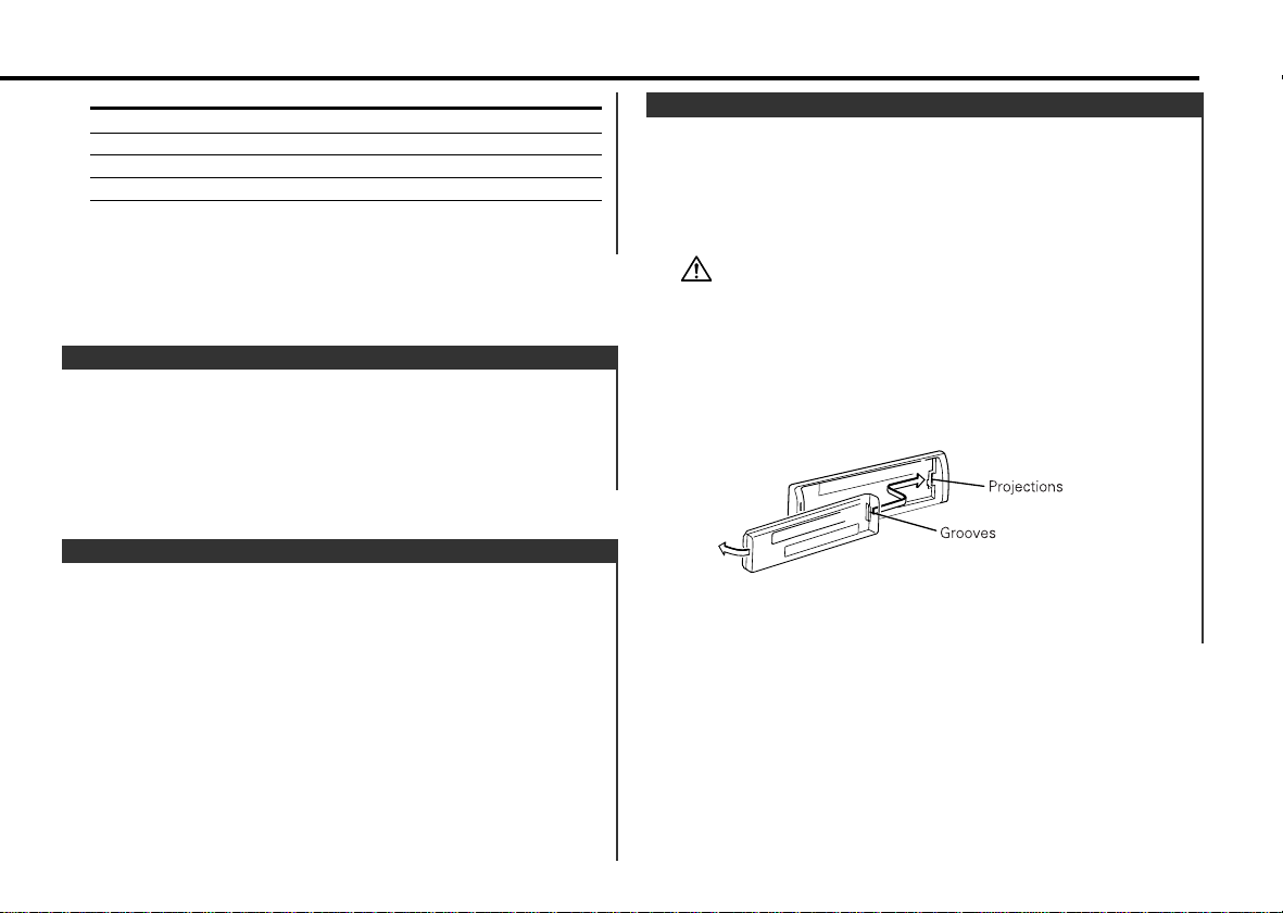
Rea tta chi ng t he Fac eplate
1 Al ign th e project ions on the uni t wit h the gr ooves on the
facep late.
2 Push t he faceplat e in unt il it cl icks.
The faceplate is locked in place, allowing you t o use the unit.
Theft Deterrent Faceplate
1 Select the clock display
Press th e [CLK] butt on.
2 Enter clock adjustm ent mode
Press th e [CLK] butt on for at least 2 seconds.
The clock display blinks.
3 Adjust the hours
Press th e [FM] or [A M] bu tton.
Adjust the m inutes
Press th e [4] or [ ¢] butt on.
4 Exit clock adjustm ent mode
Press th e [CLK] butt on.
Adjusting Clock
Swit ching t he displ ayed inf ormat ion.
Press th e [CLK] butt on.
Each time t he button is pressed it sw itches between clock
display and current source.
During clock display the clock indicator is ON.
Sw i tching Clock Display
Adjustment Item Display Range
Bass level "BAS" –4 — 4
Treble level "TRE" –4 — 4
Balance "BL" L15 — R15
Fader "FD" R15 — F15
5 Exit Audio Control mode
Press th e [A.ADJ] bu tton.
— 7 —
Page 8

Selectin g the stat ion.
1 Select tuner source
Press th e [SRC] butt on.
Select the "TUnE" display.
2 Select the band
Press th e [FM] or [A M] bu tton.
Each time t he [FM] button is pressed it swit ches betw een the
FM1, FM2, and FM3 bands.
3 Tune up or down the band
Press th e [4] or [ ¢] butt on.
During reception of stereo stations t he "STEREO" indicator is ON.
Tuning
Choo se the tun ing mod e.
Press th e [AUTO] b utton .
Each time t he button is pressed the Tuning mode switches as
show n below.
Tuning mode Display Operation
Auto seek "AUTO" Automatic search for a station.
indicator
M anual — Normal manual tuning control.
Tun i ng Mode
Tuner features
— 8 —
English
SRC
¢
4
AUTO/
AME
FM/
CRSC
AM
#1 - 6
AUTO indicator
Frequency display
STEREO indicator
Band display
Preset station number
(CRSC)indicator
Page 9

Tempor arily h ave recepti on swi tched fr om ster eo to mon o to
reduce mu lti -path no ise when listeni ng to t he FM stati on.
Press th e [CRSC] butto n for at least 1 second .
Each time t he button is pressed CRSC turns ON or OFF.
When it's ON, the " "(CRSC) indicator is ON.
CRSC (Clean Reception System Circuit)
2 Call up the station
Press th e [#1] — [#6] b utton .
Calling up the st ations i n the m emory.
1 Select the band
Press th e [FM] or [A M] bu tton.
Preset Tu n ing
Putt ing stat ions wit h good receptio n in th e memo ry
aut omaticall y.
1 Select the band for Aut o Memory Entry
Press th e [FM] or [A M] bu tton.
2 Open Auto Mem ory Entry
Press th e [AME] b utton for at least 2 seco nds.
When 6 stations that can be received are put in the m emory.
Auto Mem ory Entry closes.
Auto M e mory Entry
Putt ing th e station in the memo ry.
1 Select the band
Press th e [FM] or [A M] bu tton.
2 Select the frequency to put in the memory
Press th e [4] or [ ¢] butt on.
3 Put the frequency in the m emory
Press th e [#1] — [#6] b utton for at least 2 seco nds.
The preset number display blinks 1 time.
On each band, 1 station can be put in the m emory on each [#1]
— [#6] butt on.
Station Preset M e mory
— 9 —
Page 10

Swit ching t o the rad io auto matical ly dur ing Fast Forwar ding an d
Rewind ing.
Press th e [TC]/ [T.CALL] b utt on.
Each time t he button is pressed the Tuner Call turns ON or OFF.
When it 's ON, t he "T.CALL" indicator is ON.
Tun e r Call
Fast Forw ardi ng
Press th e [FF] butt on.
If it 's st opped press [REW] button.
Rew inding
Press th e [REW] but ton.
If it 's st opped press the [FF] button.
Fast Forwarding and Rew i nding
Wh en t he Ca sset te Tape is inse rted
Press th e [SRC] butt on.
Select the "TAPE" display.
Wh en yo u w ant to liste n to the re verse side
Press th e [REW] and [ FF] button at the sam e time.
Eje ct th e Cassette Ta pe
Press th e [0] but ton.
Playing Cassette Ta p es
Cassett e player features
— 10 —
English
0
SRC
REW
TC/
T. CALL
FF
Tape indicator
T.CALL indicator
Page 11

Fast Forw ardi ng
Hold d own o n the [¢] butto n.
Release your finger to play the disc at t hat point.
Rev ersing
Hold d own o n the [4] butto n.
Release your finger to play the disc at t hat point.
Fast Forwarding and Reversing
Playing discs set in the opt ional accesso ry disc p layer con nected
to this un it.
Press th e [SRC] butt on.
Select the display for t he disc player you want.
Disp lay exampl es:
Display Disc player
"DISC" CD player
CD changer/ MD changer
• Disc #10 is displayed as "0".
• The functions t hat can be used and the information that can be
displayed will dif fer depending on the ext ernal disc players being
connected.
Playing External Disc
Funct ion of the KRC-235
External disc control feat ures
— 11 —
SRC
¢
4
SCAN
RDM
REP
D. SCN
M .RD M
DISC+
DISC-
SCN indicator
RDM indicator
REP indicator
Disc number
Track number
Page 12

Playing all the so ngs on t he disc in random o rder.
Press th e [RDM] butt on.
Each time t he button is pressed Random Play turns ON or OFF.
When it's ON, the "RDM" indicator is ON and the track number
blinks.
When t he [¢] button is pressed, t he next song select st arts.
Random Play
Successi v ely p lay t he beg inn i ng o f each d isc on a chang er
un t il y ou f ind t he on e that you wan t to l isten to.
1 Start Disc Scan
Press th e [D.SCN] but ton.
The disc number blinks.
2 Release it when the disc you want to listen to is played
Press th e [D.SCN] but ton.
Disc Scan (Function of disc changer)
2 Release it when the song you want to listen to is played
Press th e [SCAN] bu tton.
Playing the fir st part o f each song on the d isc you ar e listeni ng
to and searching for th e song yo u want to list en to.
1 Start Track Scan
Press th e [SCAN] bu tton.
"SCN" indicator is ON.
Tra c k Scan
Replayin g the son g/disc yo u' re li stening to.
Press th e [REP] butto n.
Each time t he button is pressed the Repeat Play switches as
shown below.
Repeat play Display
Track Repeat "REP" indicator is ON & Track No. blinks.
Album Repeat "REP" indicator is ON & Disc No. blinks.
(Function of disc changer)
OFF "REP" indicator OFF.
Tra c k/Album Repeat
Selectin g the di sc you w ant to h ear.
Press th e [DISC–] or [DISC+] b utton .
Album Search (Function of disc changer)
Selectin g the son g you wan t to hear.
Press th e [4] or [ ¢] butt on.
Tra c k Search
Funct ion of the KRC-235
External disc control feat ures
— 12 —
English
Page 13

Play t he songs o n all the di scs in the d isc changer in rand om
order.
Press th e [M.RDM] bu tton.
Each time t he button is pressed the M agazine Random Play turns
ON or OFF.
When it 's ON, t he "RDM" indicator is ON and the track and disc
number blink.
When t he [¢] button is pressed, t he next song select st arts.
Magazine Random Play
(Function of disc changer)
— 13 —
Page 14

English
— 14 —
The use of any accessories except for t hose provided might result in
damage to the unit . Make sure only to use t he accessories shipped with
the unit , as shown above.
1. To prevent a short circuit, remove the key from the ignition and
disconnect t he - battery.
2. Make the proper input and output w ire connections for each unit.
3. Connect the speaker wires of the wiring harness.
4. Connect the wiring harness wires in the follow ing order: ground,
battery, ignition.
5. Connect the wiring harness connector to the unit .
6. Install the unit in your car.
7. Reconnect the - battery.
8. Press the reset button.
If you connect t he ignition w ire (red) and the battery wire (yellow )
to t he car chassis (ground), you may cause a short circuit, t hat in
turn m ay start a fire. Always connect t hose wires t o t he power
source running through t he f use box.
• If your car' s ignit ion does not have an ACC position, connect the
ignition wires t o a pow er source t hat can be turned on and off
w it h the ignition key. If you connect the ignition wire t o a pow er
source w it h a constant voltage supply, as w ith battery wires, t he
battery m ay die.
• If t he console has a lid, make sure to install the unit so that the
faceplate w ill not hit the lid when closing and opening.
• If t he fuse blow s, f irst make sure the wires aren’t t ouching t o
cause a short circuit , then replace the old fuse wit h one wit h t he
same rating.
• Insulate unconnect ed wires wit h vinyl t ape or other sim ilar
material. To prevent a short circuit, do not rem ove the caps on
the ends of t he unconnected w ires or the term inals.
• Connect t he speaker w ires correctly to t he t erminals to w hich
they correspond. The unit m ay be damaged or fail to w ork if you
share the - wires or ground t hem t o any met al part in the car.
• W hen only t wo speakers are being connected to t he syst em,
connect t he connect ors either to bot h the front out put term inals
or to bot h t he rear output term inals (do not mix front and rear).
For exam ple, if you connect t he + connector of the left speaker
to a front out put term inal, do not connect the - connect or to a
rear output t erm inal
• Af t er the unit is inst alled, check w hether the brake lamps,
blinkers, w ipers, et c. on the car are working properly.
2CAUTION
2WARNING
Accessories
Installation Procedure
.........1
1
3
5
External view
......... Number of item s
External view
......... Number of item s
.........4
4
.........2
2
.........4
.........1
Page 15

— 15 —
FRONT • LFRONT • RREAR • LREAR • R
P.CONT
ANT
CONT
FM/AM antenna input 1
Rear left out put (White) 23
Rear right output (Red) 28
Fuse (10A) 24
KENWOOD disc changer control input (KRC-235 only)
2
Wiring harness
(Accessory1)25
29
White/Black
32
Gray/Black
35
Green/Black
38
Purple/Black
White
31
Gray
34
Green
37
Purple
40
To front left
speaker 30
To front right
speaker 33
To rear right
speaker 39
To rear left
speaker 36
Power cont rol/Mot or antenna
control wire (Blue/White)
Ignition wire (Red)
20
Battery wire (Yellow ) 21
Ground wire (Black) · (To car chassis) 22
Ignition key
sw itch
10
Car fuse box
(Main fuse)
11
ACC 13
Car fuse
box 14
Battery 12
If no connect ions are made, do not
let t he wire com e out from t he tab.
4
6
Connect either t o the pow er control
term inal when using the opt ional power
amplifier, or to the antenna control
term inal in the vehicle.
To connect the Disc changer,
consult your Disc changer
manual.
3
Connect ing Wires to Terminals
Page 16

English
— 16 —
M ake sure that the unit is inst alled securely in place. If the unit is
unstable, it m ay malfunction (for example, the sound m ay skip).
M etal mounting st rap
(commercially available)
Self-tapping screw
(commercially available)
Firewall or met al support
Screw (M 4X8)
(commercially
available)
■ Installation
8 mm
MAX.
ø5mm
ø5mm
8mm
MAX.
■ Installing in Japanese-Made Cars
T: Toyota cars
N: Nissan cars
T
N
N
T
T/N
Accessory3...for Nissan car
Accessory4 ...for Toyota car
• During installation, do not use any screw s except for those provided.
The use of diff erent screw s might result in damage to the main unit.
• Damage may occur if a screwdriver or sim ilar tool is used wit h
excessive force during t he installations.
1 Refer to t he section "Rem oving the hard rubber frame" (page 17)
and then remove t he hard rubber frame.
2 Align the holes in t he unit (two locations on each side) wit h the
vehicle mount ing bracket and secure the unit with t he accessory
screw s.
3
4
Bend the t abs of the
mount ing sleeve
w ith a screwdriver or
similar utensil and
attach it in place.
Installation
Accessory5
■ Screwing the Faceplate on the Unit
Never insert t he taptite screw (ø4 × 16 mm) in any other screw hole
than the one specif ied. If you screw it in another hole, it will contact
and may cause damage to the mechanical parts inside the unit .
If you want t o fasten the
faceplate to t he main unit so
that it does not fall off,
screw in the provided screw
(ø4 X 16 mm) in the hole
shown below.
Page 17

— 17 —
■ Removing the hard rubber frame
2 When t he lower level is removed, remove t he upper two
locations.
The frame can be removed from the top side in t he same manner.
Catch
Lock
1 Engage t he catch pins on the removal tool and remove the two
locks on the lower level.
Low er t he frame and pull it forward as shown in t he f igure.
Accessory2
Removal tool
Accessory2
Removal tool
Screw (M 4X8)
(commercially
available)
■ Removing the Unit
4 Low er the removal tool
toward the bot tom, and pull
out t he unit halfway while
pressing towards the inside.
Be careful to avoid injury from
the catch pins on t he removal
tool.
5 Pull the unit all the way out
w ith your hands, being
careful not t o drop it.
1 Refer to t he section “ Removing the hard rubber frame” and then
remove the hard rubber frame.
2 Remove the screw (M 4 × 8) on the back panel.
3 Insert t he two removal tools deeply int o the slots on each side,
as shown.
Installation
Page 18

English
— 18 —
What might seem to be a malfunction in your unit may
just be the result of slight m isoperation or miswiring.
Before calling service, first check the follow ing t able
for possible problem s.
General
? The pow er does not t urn ON .
✔ The fuse has blown.
☞ Af t er checking f or short circuits in the wires, replace the fuse wit h
one w it h t he same rating.
✔ No ACC position on vehicle ignition.
☞ Connect t he same cable to t he ignit ion as the batt ery cable.
? Not hing happens w hen t he but tons are pressed.
✔ The computer chip in t he unit is not functioning norm ally.
☞ Press the reset but t on on t he unit (page 4).
? There’s a source you can’t sw it ch.
✔ There’s no tape inserted.
☞ Set t he m edia you w ant t o listen to. If t here’s no m edia in this
unit, you can't sw it ch t o each source.
? There’s a source you can’t sw it ch.
✔ The Disc changer isn’ t connected.
☞ Connect t he Disc changer. If the Disc changer isn’t connect ed to
it's input t erm inal, You can't swit ch t o an external disc source.
? The faceplate does not open or close.
✔ The faceplate is incorrectly att ached.
☞ Reattach the f aceplate correctly, See the section on < Removing
the Faceplate>(page 7).
? The mem ory is erased when t he ignit ion is turned OFF.
✔ The battery wire has not been connected t o the proper term inal.
☞ Connect t he wire correctly, referring t o the section on
<Connecting W ires to Term inals>.
✔ The ignition and battery wire are incorrectly connected.
☞ Connect t he wire correctly, referring t o the section on
<Connecting W ires to Term inals>.
? Even if Loudness is turned ON, high-pitched tone isn't compensated
for.
✔ Tuner source is select ed.
☞ High-pitched t one isn't com pensated f or when in Tuner source.
? No sound can be heard, or the volume is low.
✔ The fader or balance settings are set all the w ay to one side.
☞ Center t he f ader and balance settings.
✔ The input/output wires or wiring harness are connected incorrectly.
☞ Reconnect t he input /out put wires or t he wiring harness correctly.
See the section on "Connecting Wires to Terminals".
✔ The cassette t ape is bad.
☞ Try playing another cassette t ape. If works f ine, t he f irst tape w as
bad.
? The sound quality is poor or dist orted.
✔ One of t he speaker w ires is being pinched by a screw in the car.
☞ Check the speaker w iring.
✔ The tape head is dirty.
☞ Clean the tape head.
✔ The speakers are not wired correct ly.
☞ Reconnect t he speaker w ires so t hat each output terminal is
connected t o a diff erent speaker.
? The Touch Sensor Tone doesn’t sound.
✔ The preout jack is being used.
☞ The Touch Sensor Tone can’t be out put from t he preout jack.
Troubleshooting Guide
Page 19

— 19 —
Tuner source
? Radio recept ion is poor.
✔ The car antenna is not extended.
☞ Pull the antenna out all the way.
✔ The antenna control w ire is not connect ed.
☞ Connect t he wire correctly, referring t o the section on
<Connecting W ires to Term inals>.
Disc source
? "AVin" is displayed wit hout achieving External disc cont rol m ode.
✔ O-N swit ch is set t o "O" side.
☞ Set t he switch t o "N" side.
✔ Unsupported disc changer is connected.
☞ Connect t he support ed disc changer. (page 3)
? The specified disc does not play, but another one plays instead.
✔ The specified CD is quite dirty.
☞ Clean the CD.
✔ The CD is upside-down.
☞ Load the CD w it h t he labeled side up.
✔ The disc is loaded in a different slot f rom that specified.
☞ Eject t he disc m agazine and check the number f or t he specif ied
disc.
✔ The disc is severely scratched.
☞ Try another disc inst ead.
? The specified t rack will not play.
✔ Random play or magazine random play has been selected.
☞ Turn of f random play or magazine random play.
? Track repeat , disc repeat, track scan, random play, and magazine
random play start by t hem selves.
✔ The setting is not canceled.
☞ The sett ings f or t hese f unctions remain on until t he set t ing to off
or the disc eject ed, even if t he power is t urned of f or the source
changed.
? Cannot play CD-R or CD-RW.
✔ Finalization processing is not being conducted for CD-R/CD-RW.
☞ Conduct f inalization processing w it h CD recorder.
✔ A non-compatible CD changer is being used to play the CD-R/CD-RW.
☞ Use a CD changer com patible wit h CD-R/CD-RW to play.
?Track Search can't be done.
✔ For the albums first or last song.
☞ For each album , Track Search can't be done in t he backw ard
direction f or t he f irst song or in the f orward direction for the last
song.
If the following situat ions, consult your nearest service
center:
• Even though the disc changer is connected, the Disc Changer source is
not ON, with "AVin" showing in the display during the Changer Mode.
• Even though no device (CA-C1AX) is connect ed, t he Auxiliary input is
entered when sw itching modes.
Troubleshooting Guide
Page 20

English
— 20 —
The messages show n below display your syst em s
condition.
E-01: No disc magazine has been loaded in the changer.
The disc magazine is not completely loaded.
➪ Load the disc magazine properly.
E-02: No disc has been loaded in the disc magazine.
➪ Load a disc into t he disc magazine.
E-04: No disc has been loaded in the disc magazine.
➪ Load a disc into t he disc magazine.
The CD is quite dirty. The CD is upside-down. The CD
is scratched a lot.
➪ Clean the CD and load it correctly.
E-10: Nothing has been recorded on the MD.
E-11: No tracks are recorded on the M D, although it has a
tit le.
E-30: The faceplate of t he slave unit being connected to
this unit has been removed.
➪ Replace it.
E-77: The unit is malfunct ioning for some reason.
➪ Press the reset button on the unit. If the "E- 77"
code does not disappear, consult your nearest
service center.
E-99: The unit is malfunct ioning for some reason.
➪ Press the reset button on the unit. If the "E-99"
code does not disappear, consult your nearest
service center.
E-0d: The protective circuit in the unit activates when t he
temperature inside the autom atic disc changer
exceeds 60°C (140°F), stopping all operation.
➪ Cool down the unit by opening the w indows or
turning on t he air conditioner. As the temperature
falls below 60°C (140°F), the disc will start playing
again.
LOAd: Discs are being exchanged in the Disc changer.
2 3 (Blink): The tape player section is not operating properly.
➪ Reinsert the Tape. If the tape cannot be ejected or
the display continues t o flash even when the tape
has been properly reinserted, please swit ch off the
power and consult your nearest service center.
Troubleshooting Guide
Page 21

— 21 —
FM tuner sect ion
Frequency range (200 kHz space) .............87.5 MHz –108.0 MHz
Usable sensitivity (S/N = 30dB)...................9.3 dBf (0.8 µV/ 75 Ω)
Quieting Sensitivit y (S/N = 50dB) ..............15.2 dBf (1.6 µV/75 Ω)
Frequency response (± 3.0 dB) ..............................30 Hz – 15 kHz
Signal t o Noise ratio (M ONO) ..............................................70 dB
Selectivity (±400 kHz).......................................................≥ 80 dB
Stereo separat ion (1 kHz) ....................................................40 dB
AM tuner section
Frequency range (10 kHz space) ...................530 kHz – 1700 kHz
Usable sensitivity (S/N = 20dB).............................28 dBµ (25 µV)
Cassett e player section
Tape Speed...............................................................4.76 cm/sec.
Wow & Flutt er (WRM S)....................................................0.12 %
Frequency response (±3.0 dB) (120 µs).................30 Hz – 14 kHz
Separation (1 kHz) ...............................................................40 dB
Signal t o Noise ratio ............................................................52 dB
Audio sect ion
M aximum output power.................................................40 W x 4
Full Bandwidt h Pow er (at less than 1% THD)................20 W x 4
Tone action
Bass : ...............................................................100 Hz ±10 dB
Treble : .............................................................10 kHz ±10 dB
Preout level / Load.............................................1800 mV / 10 kΩ
Preout impedance ............................................................≤ 600 Ω
General
Operating voltage (11 – 16V allowable) ..............................14.4 V
Current consumpt ion .............................................................10 A
Installation Size (W x H x D) ..........................182 x 53 x 158 m m
7-3/16 x 2-1/16 x 6-1/4 inch
Weight ...................................................................2.9 lbs (1.3 kg)
Specificat ions subject t o change w ithout not ice.
Specificat ions
 Loading...