

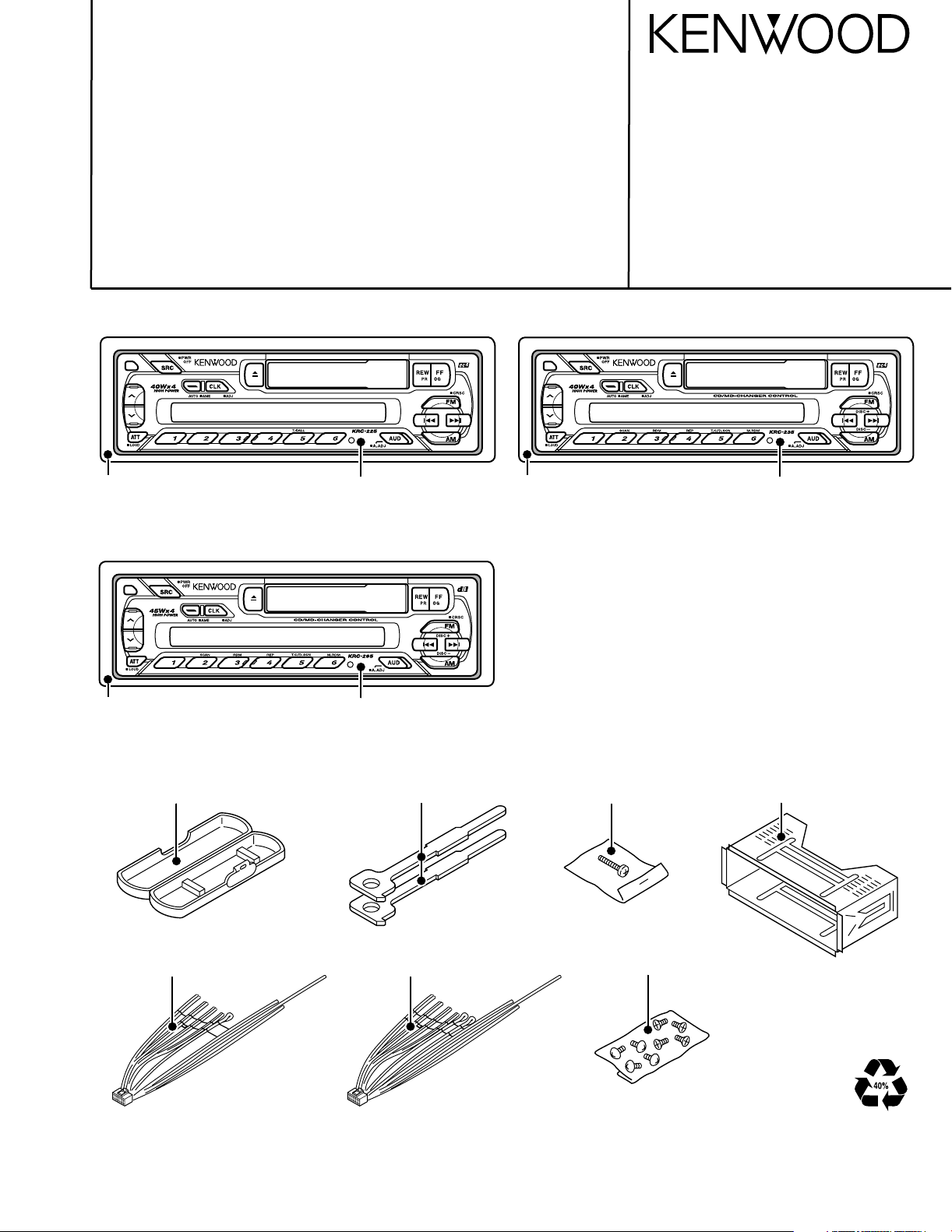
CASSETTE RECEIVER
KRC-225/235
SERVICE MANUAL
© 2001-11 PRINTED IN KOREA
B51-7854-00 (K) 1748
KRC-265/S
KRC-265/S
KRC-235
KRC-225
Panel assy
(A64-2505-02)
Plastic cabinet assy
(A02-1486-13)
Lever
(D10-3031-04)x2
Mounting hardware assy
(J21-9491-13)
DC cord
(E30-4783-05):KRC-225/235
DC cord
(E30-4784-05):KRC-265/S
Screw set
(N99-1610-15)
Screw set
(N99-1719-05)
Escutcheon
(B07-2124-02)
Panel assy
(A64-2506-02)
Escutcheon
(B07-2124-02)
Panel assy
(A64-2507-02):KRC-265
(A64-2634-02):KRC-265S
Escutcheon
(B07-2124-02):KRC-265
(B07-3049-02):KRC-265S
2
IC1
KEY
PAN 5V
MUTE
B.U. DET.
B.U.
ACC
P-CONT.
MUTE
PRE
POWER IC
EQ. AMP.
CH ISO AMP
N.C.MPX
E-VOL.
CD/MD
CHANGER
FRONT Lch
FRONT Rch
REAR Lch
REAR Rch
J2
LCD DRIVER
LCD
MAIN
TAPE MECHA.
IC5
1 Lch
2 Rch
PRE OUT
IC2
IC4
IC3 Q150,153
SP OUT
REAR
J4
RST
PAN IN SW
ANT-CONT.
P-CONT.
J2
Q370,371
Q450,451
Q50
Q350-353
Q58-61
Q54-57
Q53
Q320
Q301
Q51,52
J5
IC1
ED1
FM+B
Q200,201
AM+B
Q202,203
AM BPF
FM BPF
SW 5V
COM +B
ILLUMI.
B.U.5V
SYSTEM MI-COM
RST SW
ANT-CONT.
FM ANT
AM ANT
RF GND
FM+B
AM+B
OSC GND
OSC GND
OSC GND
VT
PLL +B
IFC OUT
SDA
SCL
DIG GND
IF1+B
IF1 GND
S-METER
IF2 GND
SD
FM+B
SW5V
ACC DET
B.U. DET
SCL
MUTE
SDA
P CON
PANEL
HOLD
L CLK
L DATA S
L DATA L
FWD/REV
MOTOR
CH CON
DATA H
DATA C
REQ H
REQ C
CH CLK
Rch
COM
Lch
TAPE
MP IN
AM
MPX
OUT RR
OUT LR
OUT RF
Rch
LEVEL
SCL
SDA
OUT LF
Rch
STBY
MUTE
Rch
Lch
T-MUTE
FWD
REV
B.U.5V
B.U.
8V
B.U.
CHRST
S MUTE
8
4
6
5
B.U.5V
AM+B
VDD 5V
PACK IN
L CE
ANT CON
CHMUTE
BEEP
SVR
AMP. STBY
SVR
AC GND (BEEP)
Lch Lch
Rch
Lch
1200mV
TAPE :1681mV
CD/MD-CH :3529mV
AM :546mV
FM :1781mV
8V
RF GND
OSC GND
IF2 +B
AUDIO OUT
8V
S-METER
SD
PLL CLK
PLL DATA
HEAD
PLAY
R
55.6mV
BU5V
SW5V
8V
B.U.5V
AM: 170mV
FM: 400mV
L
PACK IN
(FF/REW)
AMP. MUTE
FF/REW
BU5V
ILL
P-CONT.
/ANT-CONT.
(X16-)
(X14-)
M
KRC-265/S
KRC-225/235
KRC-235,265/S
A1
MOTOR SW
Q260,261
ACC. DET.
5V
Q1
,Q151
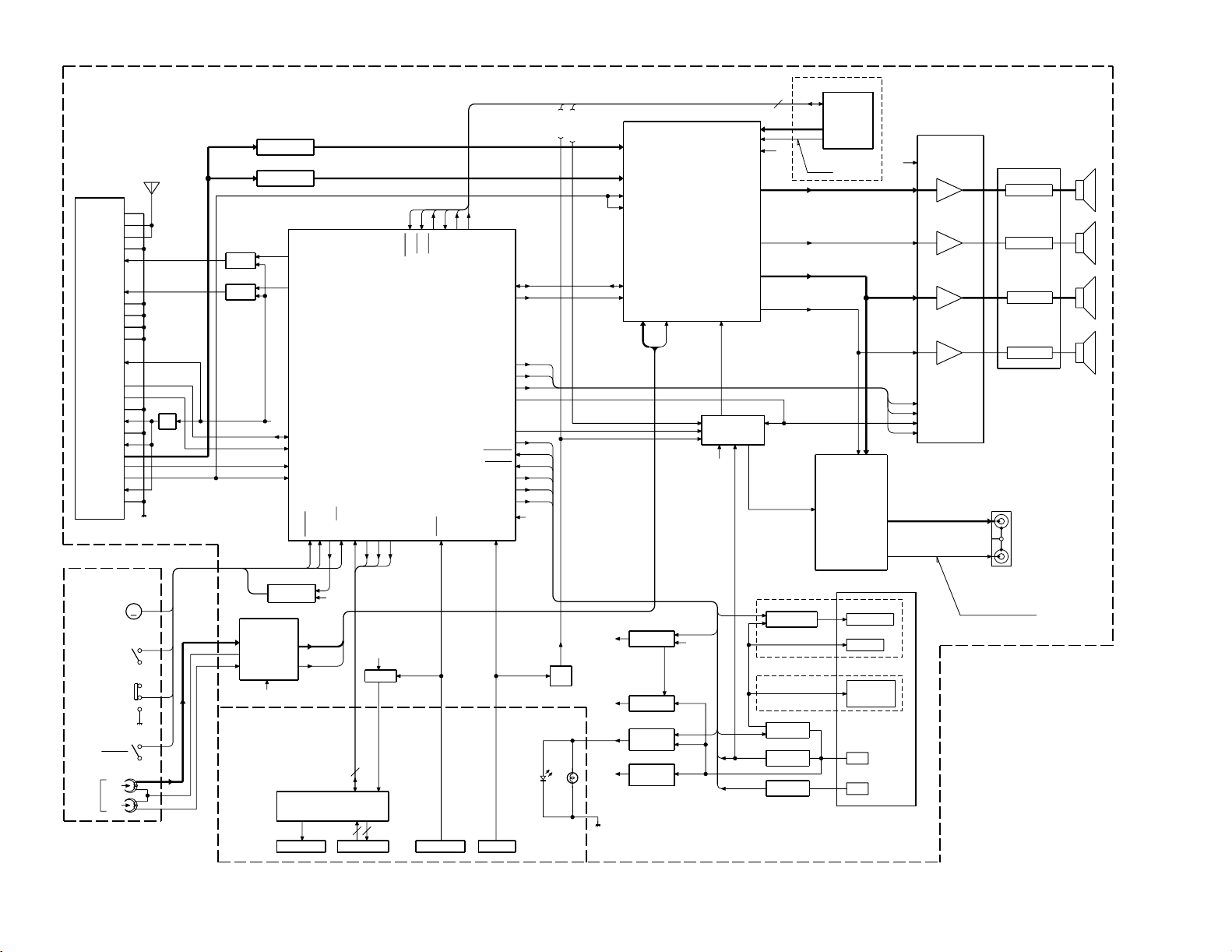
KRC-225/235/265/265S
BLOCK DIAGRAM
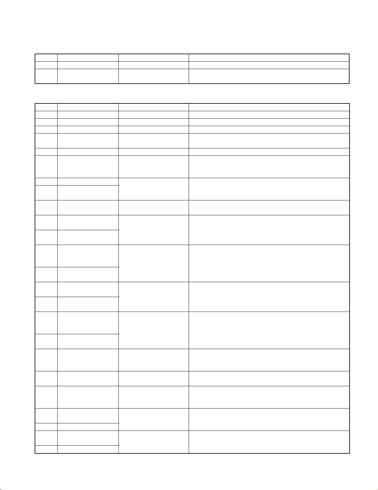
KRC-225/235/265/265S
COMPONENT DESCRIPTION
¶SWITCH UNIT(X16-1490-XX)
Ref.No. Component Name Application/Function Operation/Condition/Compatibility
IC1 LC75853NE LCD driver with key-matrix
DTA114EK or UN2111
Q1
or KRA102S
¶SYNTHESIZER UNIT(X14-6850-XX)
Ref.No. Component Name Application/Function Operation/Condition/Compatibility
IC1 LC72366-9592 System MI-COM. System control
IC2 TDA7461ND E-VOL. & N.C. MPX Controls sound volume. Selects each source.
IC3 HD74HC27FP Mute logic 3-input NOR gate x 3
IC4
IC5 LA3161 Equalizer amplifier Equalizer amplifier for cassette tape sound
Q50
Q51 2SB1443
Q52
Q53
Q54
Q55
Q56 (P) or 2SB1565(E,F) While Q57's base becomes Hi, Q56 is turned on.
Q57
Q58
Q59
Q60 (P) or 2SB1565(E,F) While Q61's base becomes Hi, Q60 is turned on.
Q61
Q150
Q151
Q153
Q200
Q201 2SB1277(Q,R) Works during FM reception mode.
Q202
Q203 2SB1277(Q,R) Works during AM reception mode.
TDA7384A or
TDA7386
2SC2412K or
2SD601A
2SC2412K or BACK-UP 5V AVR
2SD601A
DTA114YK or UN2114
or KRA107S
DTC144EK or UN2213
or KRC104S
DTA124EK or UN2112
or KRA103S
2SA2057 or 2SB1548
or 2SB1655(E,F) COM+B AVR
2SC2412K or
2SD601A
DTC144EK or UN2213
or KRC104S
DTA124EK or UN2112 Works during POWER ON mode with a panel attached
or KRA103S to the set.
2SA2057 or 2SB1548
or 2SB1655(E,F) Illumination +B driver
2SC2412K or
2SD601A
DTC124EK or UN2212
or KRC103S
DTC114YK or UN2214
or KRC107S Q151 is turned on.
DTA124EK or UN2112
or KRA103S
DTC124EK or UN2212
or KRC103S FM +B SW
DTC124EK or UN2212
or KRC103S AM +B SW
Key-matrix permission SW Ready on key-matrix
Power IC Amplifies power so that the speaker can drive audio signal.
BACK-UP detection
(Momentary power down
detection) SW
P.ON 5V SW While a base becomes Lo, Q53 is turned on.
COM+B SW
Illumination +B SW
Electric volume mute SW MI-COM.'s mute works, a base becomes Hi, and Q150
SVR discharge SW
Pre-out mute driver MI-COM.'s mute works, a base becomes Lo, and Q153
While BACK-UP is added, a base becomes Hi, and Q50 is
turned on.
While BACK-UP is added, AVR outputs +5V.
Q51 and Q52 is inverted Darlington connection.
While Q54's base becomes Hi, Q55 is turned on.
Works during POWER ON mode.
Q56 and Q57 is inverted Darlington connection.
While Q58's base becomes Hi, Q59 is turned on.
Q60 and Q61 is inverted Darlington connection.
When BACK-UP detection SW or CHANGER RESET SW or
is turned on.
When POWER IC RESET is activated, a base becomes Hi,
When BACK-UP detection SW or CHANGER RESET SW or
is turned on.
Q201 is turned on when Q200's base becomes Hi.
Q203 is turned on when Q202's base becomes Hi.
3
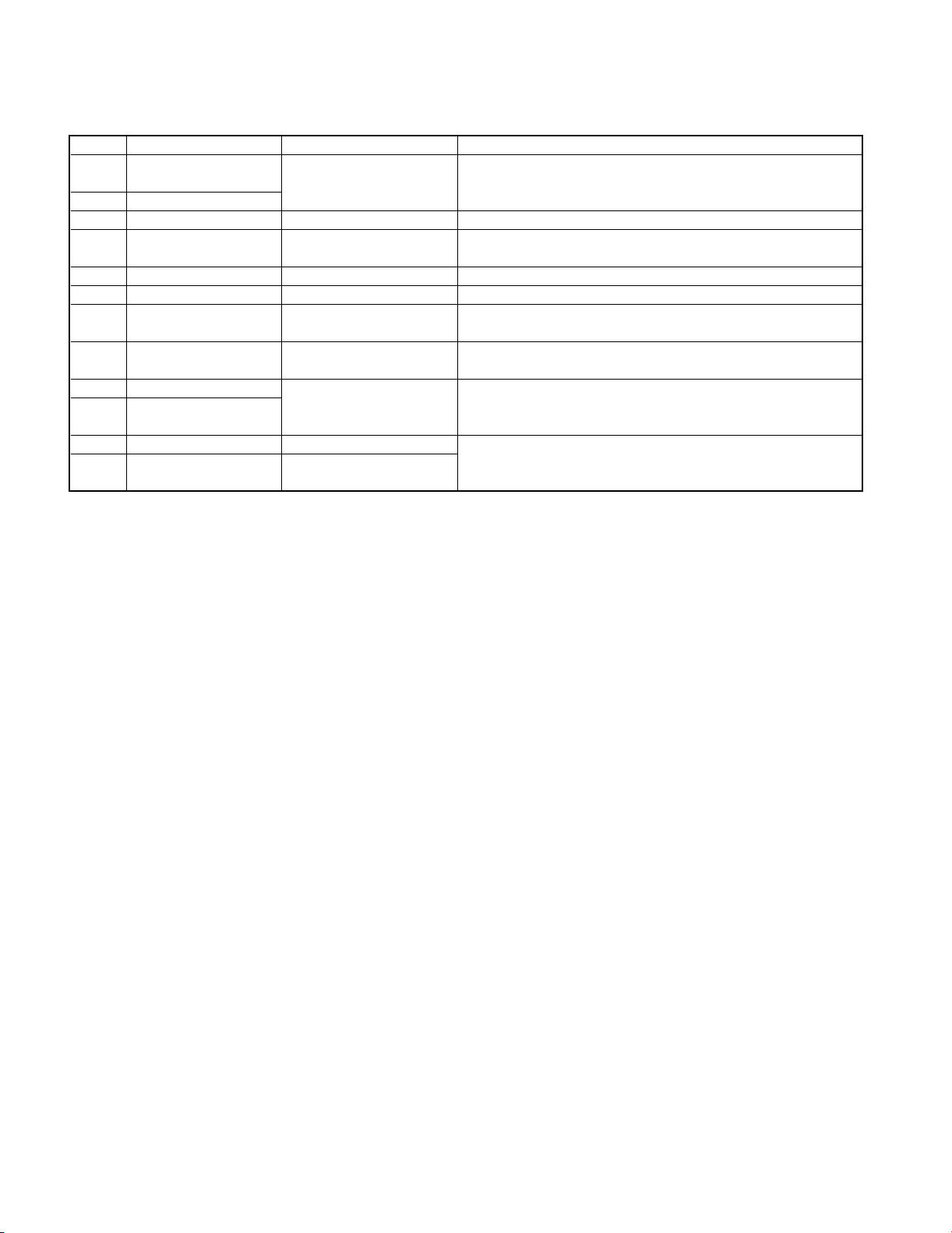
KRC-225/235/265/265S
COMPONENT DESCRIPTION
¶SYNTHESIZER UNIT(X14-6850-XX)
Ref.No. Component Name Application/Function Operation/Condition/Compatibility
Q260
Q261 2SB1443 Works during TAPE mode.
Q301 DTA144EK or UN2113 Changer reset SW When a base becomes Lo, Q301 is turned on.
Q320 2SA1037K Panel 5V SW
Q350 2SB1277(Q,R) P-CON. driver When Q353's base becomes Hi, Q350 is turned on.
Q351 2SA1037K P-CON. protection SW Works when P-CON is being short-circuited on GND.
Q352
Q353
Q370 2SB1277(Q,R) Q370 is turned on when Q371's base becomes Hi.
Q371
Q450 DTC143TK or UN2216 Pre-out mute SW (R ch.) When BACK-UP detection SW or CHANGER RESET SW or
Q451 DTC143TK or UN2216 Pre-out mute SW (L ch.)
DTC114YK or UN2214
or KRC107S Motor +B SW
DTA124EK or UN2112 P-CON. protection
or KRA103S inhibit SW
DTC114YK or UN2214
or KRC107S POWER ON mode.
DTC114YK or UN2214 ANT-CON. SW
or KRC107S
P-CON. SW
When Q260's base becomes Hi, Q261 is turned on.
While a panel is attached to the set, a base becomes Lo, and
Q320 is turned on.
Inhibits protection SW function when P-CON works momentary.
Q353 is turned on when a base becomes Hi. Works during
Works during TUNER mode.
MI-COM.'s mute works, a base becomes Hi, and Q450,451
are turned on.
4
KRC-225/235/265/265S
MICROCOMPUTER'S TERMINAL DESCRIPTION
¶Terminal Description ( IC1 : X14-6850-XX)
Pin No. Pin Name I/O Description Processing Operation
1 XIN I Main clock resonator connection terminal
2 GND - TEST terminal 2 Connected to GND lines.
3 L DATA L I Data input from the LCD driver IC
4 L DATA S O Data output to the LCD driver IC
5 L CLK O Clock output to the LCD driver IC
6 L CE O CE output to the LCD driver IC
7 SDA I/O Data input/output with the E-VOL. IC
8 PLL DATA I/O Data input/output with the F/E
9 PLL CLK O Clock output to the F/E
10 SD I SD input from the F/E Hi : Station detected
11 DATA C I Data input from changers
12 DATA H O Data output to changers
13 CH CLK I/O Clock input/output with changers
14 - O - N.C.(Not used)
15 MOTOR O Cassette motor on/off output Hi : Motor ON
16 SCL O Clock output to the E-VOL. IC
17-24 - O - N.C.(Not used)
25 AM+B O AM+B ON/OFF output Hi : during AM reception
26 FM+B O FM+B ON/OFF output Hi : during FM reception
27 PACK IN I Cassette tape Pack-in detection input Lo : Pack-in
28 FF/REW I FF/REW detection input Lo : FF/REW, Hi : PLAY
29 GND I - Connected to GND lines.
30 GND I - Connected to GND lines.
31 VDD - Positive power supply connection terminal Connected to B.U. 5V lines.
32 REQ C I Request input from changers Lo : Request
33 MUTE O Audio mute on/off output Hi : Mute ON
34 CH CON O Changer control Lo : Standby, Hi : ON
35 REQ H O Request output to changers Lo : Request
When the momentary power down, after ACC
36 SVR O Power IC reset terminal ON/OFF is detected and after POWER OFF,
the output becomes Hi temporarily.
37 AMP STBY O Power IC standby control output Hi : POWER ON mode
38 AMP MUTE O Power IC mute control Lo : Mute
39 P CON O Power control Hi : POWER ON mode
40 ANT CON O Antenna control Hi : during FM/AM reception
41 SW5V O SW 5V control Lo : POWER ON mode
42 ILL O Illumination AVR ON/OFF control terminal Hi : POWER ON mode
43 - O - N.C.(Not used)
44 BEEP O BEEP sound output
45-47 - O - N.C.(Not used)
48 ROLL OFF I Roll off input Pull down to GND lines. (Not used)
49
50 SEL1 I Destination input 1 Lo : KDC-225, Hi : KDC-235,265/S
51 SEL2 I Destination input 2 Lo : KDC-265/S, Hi : KDC-225,235
52 SEL3 O Destination input 3 N.C.(Not used)
53 EQ MUTE O Tape equalizer mute on/off output N.C.(Not used)
54 FWD/REV I FWD/REV mode detection input Lo : REV mode
55 - O - N.C.(Not used)
56 REMO I
57-60 - O - N.C.(Not used)
NOISE
CANCELLER
I Noise canceller input Pull down to GND lines. (Not used)
Data input from the remote control KDC-225/235:Pull up to PON5V lines. (Not used)
light sensor KDC-265/S:Pull down to GND lines. (Not used)
5

KRC-225/235/265/265S
MICROCOMPUTER'S TERMINAL DESCRIPTION
¶Terminal Description ( IC1 : X14-6850-XX)
Pin No. Pin Name I/O Description Processing Operation
61 ACC DET I ACC detection input Hi : ACC ON
62 B.U. DET I Momentary power down detection input
63 S METER I S-meter input from the F/E
64 PANEL I Panel detaching detection input Lo : Panel not detached
65 GND I - Connected to GND lines.
66 GND I - Connected to GND lines.
67 HOLD I MI-COM. HOLD input Lo : Hold
68 VDD - VDD connection terminal Connected to B.U. 5V lines.
69 GND I - Connected to GND lines.
70 GND I - Connected to GND lines.
71,72 - O - N.C.(Not used)
73 VDD - Positive power supply connection terminal Connected to B.U. 5V lines.
74 GND I - Connected to GND lines.
75 GND I - Connected to GND lines.
76 VSS - Ground connection terminal Connected to GND lines.
77,78 - O - N.C.(Not used)
79 GND - TEST terminal 1 Connected to GND lines.
80 XOUT O Main clock resonator connection terminal
Hi : When momentary power down detected or
B.U. OFF, Lo : B.U. ON
6

KRC-225/235/265/265S
TEST MODE
1. How to enter the test mode
• Reset the unit while holding the FM key and preset 6
key.
• All indication segments go ON at the beginning of
the test mode.
2. How to release the test mode
• Simply reset the unit.
• (NOTE) The test mode is not canceled by ACC OFF,
power OFF, momentary power down or the panel
off.
3. Audio adjustment
• Set the volume level to -10dB (which is shown as
"30" on the display).
• Loudness OFF.
• The BASS / TREBLE and BALANCE / FADER controls can be set to the full boost / full cut and full right
/ full left and full front / full rear respectively by pressing the Track Up / Track Down keys.
• Sound coordination doesn't appear for the Audio
mode feed.
7
 Loading...