

Kenwood KRC-189 Service Manual
CASSETTE RECEIVER
KRC-189
SERVICE MANUAL
© 2000-10 PRINTED IN JAPAN
B51-7674-00 (N) 484
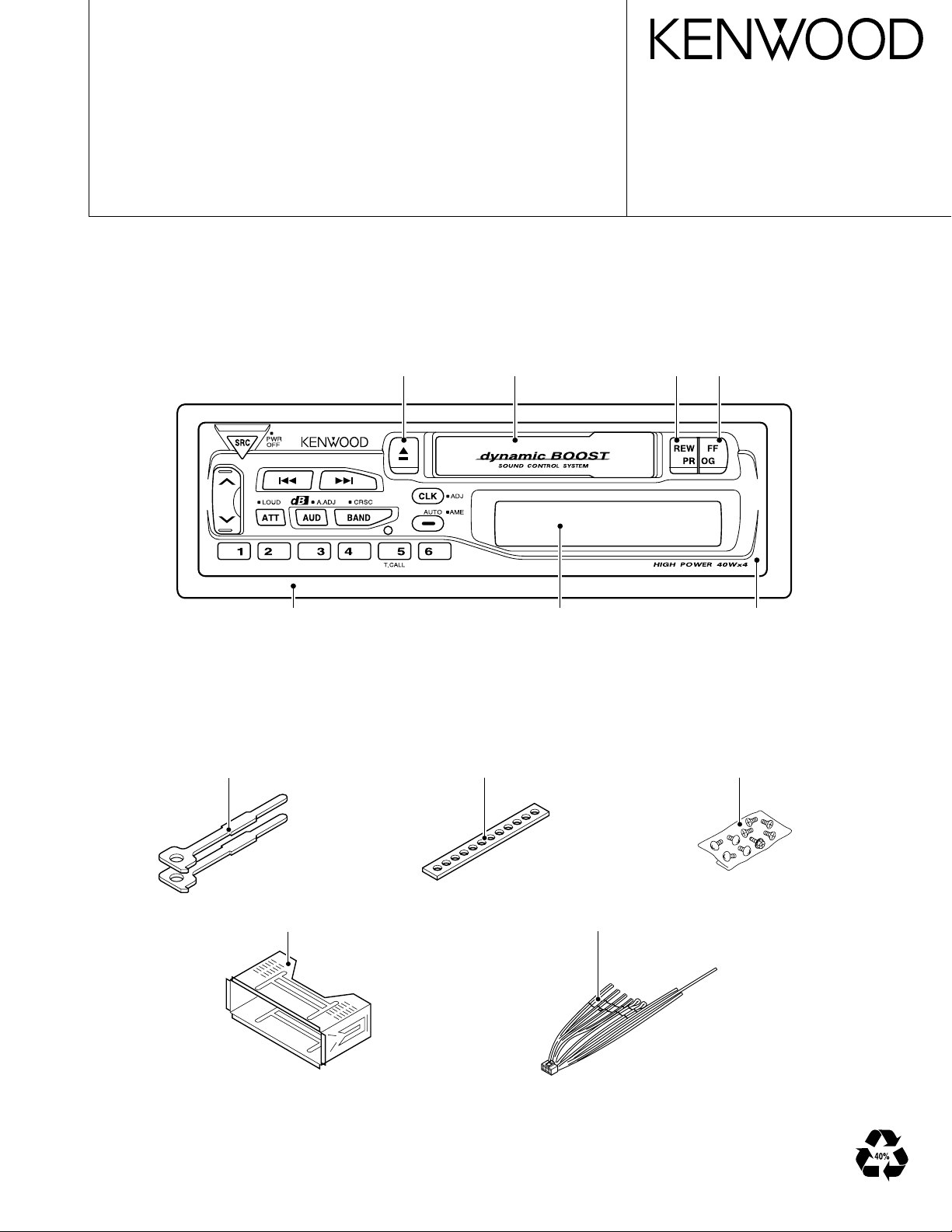
Escutcheon
(B07-2188-02)
Lever
(D10-3031-04)×2
Knob (EJECT)
(K27-3554-03)
Cassette lid
(A53-1677-03)
Stay
(J54-0606-04)
Knob (REW)
(K27-3556-04)
LCD
(B51-1024-05)
Knob (FF)
(K27-3555-04)
KRC-189
Panel assy
(A64-2313-02)
Screw set
(N99-1632-05)
Mounting hardware assy
(J21-9491-13)
DC cord
(E30-4784-05)
2
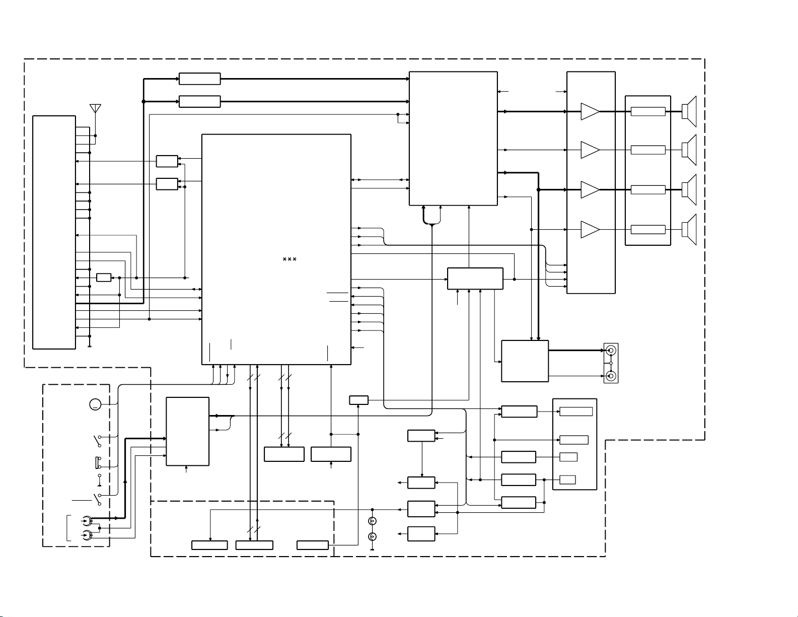
IC1
KEY
MUTE
B.U DET.
B.U
ACC
P-CONT.
MUTE
PRE
POWER IC
EQ. AMP
AMP
NC/MPX
E-VOL.
FRONT Lch
FRONT Rch
REAR Lch
REAR Rch
J2
LED
TAPE MECHA
MAIN
IC5
1 Lch
2 Rch
PRE OUT
IC2 IC4
IC3
SP OUT
REAR
RST SW
RST IC
PST9130NR
IC6
ACC DET.
P-CONT.
ANT-CONT
J2
J5
HD74HC27FP
40W TDA7384A
FM+B
Q201
AM+B
Q203
5V
AM BPF
FM BPF
Q450,451
Q62
Q50
Q350
Q53
SW5V
Q56
8V
Q60
ILLUMI
BU5V
Q51
SYSTEM u-COM
TDA7400D
RST
Q370
ANT-CONT
LA3161
M38258MCD FP
7SEG LCD
ED1
FM ANT
AM ANT
RF GND
FM+B
AM+B
OSC GND
OSC GND
OSC GND
VT
PLL +B
IFC OUT
SDA
SCL
DIG GND
IF1+B
IF1 GND
S-METER
IF2 GND
SD
FM+B
PON
ACC DET
B.U DET
SCL
MUTE
SDA
P CON
RESET
FWD/REV
MOTOR
Rch
COM
Lch
TAPE
MP IN
AM
MPX
OUT RR
OUT LR
OUT RF
LEVEL
SCL
SDA
OUT LF
STBY
MUTE
Rch
Lch
T-MUTE
FWD
REV
B.U
SMUTE
9
(FF/REW)
BU5V
AM+B
VDD 5V
PACK IN
ANT CON
BEEP
SVR
AMP. STBY
SVR
AC GND(BEEP)
Rch
Lch
TAPE :1681mV
AM :546mV
FM :1781mV
8V
RF GND
OSC GND
IF2 +B
AUDIO OUT
8V
S-METER
SD
PLL-SCL
PLL-SDA
HEAD
R
55.6mV
BU5V
B.U.5V
8V
BU5V
AM: 170mV
FM: 400mV
L
PAC K
IN
PLAY
FF/REW
ILL
9
KS0-KS4
KI0-KI3
25
25
SEG1-SEG22
COM1-COM3
AMP. MUTE
8V
BU5V
(X13)
M
F/E
KRC-189
BLOCK DIAGRAM

MICROCOMPUTER’S TERMINAL DESCRIPTION
Microcomputer (M38258MCD070FP : IC1 : X14)
●Terminal description
Pin No.
19-25 O (NC) Not used.
36,37 O (NC) Not used.
I/O Pin Name Description
1 I (NC) Not used.
2 I VL1 LCD power input.
3-5 I KI0-2 Key return input.
6-9 O KS0-3 Key scan output.
10 I SMETER Signal meter.
11 O KS4 Key scan output.
12 O BEEP Beep output.
13 O (NC) Not used.
14 O MOTOR Mechanism motor ON/OFF.
15 I FF/REW
16 I PACK_IN
17 I KI3 Key return input.
18 I FWD/REV
26 I SD Station detection.
27 O PLL_CLK IC3 clock output.
28 I/O PLL_DATA IC3 data input/output.
29 I IFC AM bandwidth.
30 O AM+B AM power output.
31 O FM+B FM power output.
32 O SCK IC2 clock output.
33 I/O SDA IC2 data input/output.
34 O (NC) Not used.
35 I RESET Reset input.
38 - X_IN Clock input.
39 - X_OUT Clock output.
40 - Vss Power input (0 V).
41 I IC2_TYPE1 IC2 constant switching.
42 I IC2_TYPE2 IC3 constant switching.
43 O (NC) Not used.
44 I SEL1 Destination type switching.
45 I SEL2 Destination type switching.
46 O MUTE Muting ON/OFF.
47 O STBY Power IC standby control.
48 O SVR Power IC SVR control.
49 I ACC_DET Acc detection.
50 I BU_DET
Mechanism FF/RWD detection.
Mechanism cassette pack-in detection.
Mechanism play direction detection.
Momentary power down detection.
KRC-189
Pin No.
58-64 O (NC) Not used.
65,66 O (NC) Not used.
67,68 O (NC) Not used.
69-90 O SEG22-1 LCD segment output.
I/O Pin Name Description
51 O P_MUTE Power IC muting control.
52 O ANT_CON External antenna control.
53 O P_CON Power control output.
54 O ILLUM_ON Illumination control.
55 O (NC) Not used.
56 O SW5 5V power control.
57 O EQ_MUTE Equalizer muting.
91 - Vcc Power input (5 V).
92 - VREF A/D reference voltage input.
93 - Avss Analog power input (Vss).
94 O (NC) Not used.
95 O COM3 LCD common output.
96 O COM2 LCD common output.
97 O COM1 LCD common output.
98 I VL3 LCD power input.
99 I VL2 LCD power input.
100 I (NC) Not used.
3
KRC-189
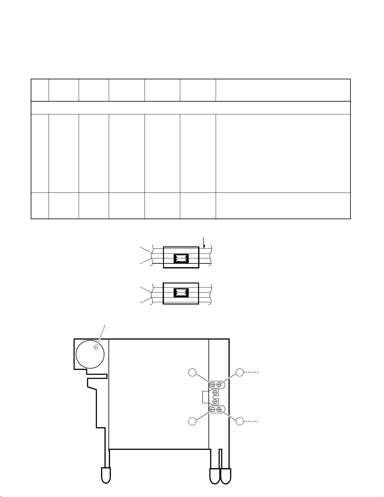
ADJUSTMENT
Set the controls and switches as follows.
BALANCE : center position BASS : center position LOUD : OFF DOLBY NR : OFF
FADER : center position TREBLE : center position
No. ITEM
CASSETTE DECK SECTION
[1]
[2]
HEAD
HEIGHT
HEAD
AZIMUTH
TAPE
SCC-1659 – TAPE PLAY
TCC-153
10kHz
OUTPUT
SETTINGS
Connect a
AC voltmeter
to SP out.
B
A
RECEIVER
SETTINGS
TAPE PLAY
ALIGNMENT
POINTS
Head Height
Screw
Head Azimuth
Screw
(2-LINE TAPE)
(FWD)
ALIGN FOR
1) During FWD transport adjust (F) and (F’) so that
line A of 2-LINE TAPE passes trough the center of
the head shield plate (core center area)
2) During RVS transport adjust screws (R) and (R’)
so that line B of 2-LINE TAPE passes trough the
center of the head shield plate (core center area)
3) After the alignment above, reverse the transport direction and check the FWD alignment again.
If it is deviated, perform alignment again. (Tape
used : SCC-1659, manufactured by A-BEX)
Adjust the azimuth for each Lch/Rch or FWD/RVS
becomes maximum
TAPE SPEED
B
A
(RVS)
HEIGHT
(FWD)
HEIGHT/AZIMUTH
(FWD)
’’
F
F
R
R
HEIGHT
(RVS)
HEIGHT/AZIMUTH
(RVS)
4
 Loading...