

Page 1

KRC-152LA
KRC-152LG
CASSETTE RECEIVER
INSTRUCTION MANUAL
© B64-1193-00 (EN)
Page 2

Contents
Before use
Safety precautions ........................................................................3
English
Buttons and Display
Basic operations............................................................................4
Tuner features...............................................................................5
Cassette player features ...............................................................5
Other features...............................................................................6
Basic operations
Power............................................................................................6
Switching Modes ..........................................................................6
Volume..........................................................................................6
Attenuator .....................................................................................7
Loudness ......................................................................................7
Tuner features
Tuning...........................................................................................7
Monaural Reception......................................................................8
Station Preset Memory.................................................................8
Auto Memory Entry.......................................................................8
Cassette player features
Playing Cassette Tapes.................................................................9
Fast Forwarding and Rewinding Cassette Tapes..........................9
Tuner Call Function .......................................................................9
Other features
Audio Control Setting..................................................................10
Clock Display...............................................................................10
Adjusting Time ............................................................................10
Theft Deterrent Faceplate...........................................................11
Installation
Accessories.................................................................................11
Installation Procedure..................................................................12
Connecting Cables to Terminals.................................................14
Installation...................................................................................14
Troubleshooting guide .......................................................16
Specifications .........................................................................17
— 2 —
Page 3
Safety precautions
AUTO
AME
CLK
MONO
LOUD
2WARNING
To prevent injury and/ or fire, take the
following precautions:
• Insert the unit all the way until it is fully
locked in place. Otherwise it may fly out of
place during collisions and other jolts.
• When extending the ignition, battery or
ground cables, make sure to use automotivegrade cables or other cables with an area of
0.75mm2(AWG18) or more to prevent cable
deterioration and damage to the cable coating.
• To prevent short circuits, never put or leave
any metallic objects (e.g., coins or metal
tools) inside the unit.
• If the unit starts to emit smoke or strange
smells, turn off the power immediately and
consult your Kenwood dealer.
• Be careful not to drop the unit or subject it to
strong shock.
The unit may break or crack because it con-
tains glass parts.
• Do not touch the liquid crystal fluid if the LCD
is damaged or broken due to shock. The liquid crystal fluid may be dangerous to your
health or even fatal.
If the liquid crystal fluid from the LCD contacts your body or clothing, wash it off with
soap immediately.
2CAUTION
To prevent damage to the machine,
take the following precautions:
• Make sure to ground the unit to a negative
12V DC power supply.
• Do not open the top or bottom covers of the
unit.
• Do not install the unit in a spot exposed to
direct sunlight or excessive heat or humidity.
Also avoid places with too much dust or the
possibility of water splashing.
• Do not set the removed faceplate or the face-
plate case in areas exposed to direct sunlight,
excessive heat or humidity. Also avoid places
with too much dust or the possibility of water
splashing.
• Do not subject the faceplate to excessive
shock, as it is a piece of precision equipment.
• To prevent deterioration, do not touch the
terminals of the unit or faceplate with your
fingers.
• When replacing a fuse, only use a new one
with the prescribed rating. Using a fuse with
the wrong rating may cause your unit to malfunction.
• To prevent short circuits when replacing a
fuse, first disconnect the wiring harness.
• During installation, do not use any screws
except for the ones provided. The use of
improper screws might result in damage to
the main unit.
— 3 —
NOTE
• If you experience problems during installa-
tion, consult your Kenwood dealer.
• If the unit does not seem to be working right,
try pressing the reset button first. If that does
not solve the problem, consult your Kenwood
dealer.
Reset button
Cleaning the Unit
If the front panel gets dirty, turn off the
power and wipe the panel with a dry silicon
cloth or soft cloth.
2CAUTION
Do not wipe the panel with a stiff cloth or a
cloth dampened by volatile solvents such as
paint thinner and alcohol. They can scratch
the surface of the panel and/or cause the
indicator letters to peel off.
Cleaning the Faceplate Terminals
If the terminals on the unit or faceplate get
dirty, wipe them with a dry, soft cloth.
Page 4
Safety precautions
AUTO
AME
CLK
LOUD
u d
SRC/
PWR OFF
ATT LOUD
MONO
Cleaning the Tape Head
After you have used the tape player many times over a long period,
magnetic powder from the tapes and dust accumulates on the tape
head, causing noise and a deterioration in sound quality. Clean the
English
tape head using a cleaning tape or cleaning kit designed for use in car
audio systems.
Handling Cassette Tapes
• Do not play a cassette whose tape has gone slack. In such a case,
wind it tight using a pencil or the like in one of the spools. Playing
slack cassette tapes can result in the tape tangling around the capstan and/or pinch rollers, causing trouble.
• Do not play a deformed cassette or one whose label is starting to
come off, as it can cause the unit to malfunction.
• Do not leave tapes in hot places, such as above the fascia panel
(dashboard) and other spots exposed to direct sunlight, or near
heater outlets. They can deform the cassette.
• Avoid using extremely long cassette tapes, such as 100-minute-long
tapes. Such tapes are very thin, and can tangle easily around the
pinch rollers or other parts inside the unit, causing unit failure.
• Remove a cassette tape from the unit when not listening to it for a
whilst. If you leave a tape in the unit too long, it may stick to the tape
head and cause unit malfunction.
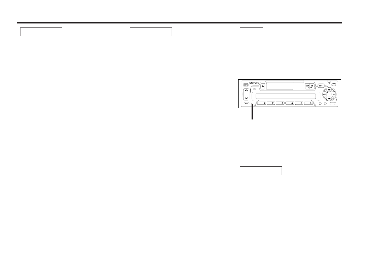
Buttons and Display
Basic operations
LOUD indicator
Volume
ATT indicator
— 4 —
Page 5
SRC
FM/
MONO
AM
4 ¢
AUTO/AME#1-6
AUTO
AME
CLK
MONO
LOUD
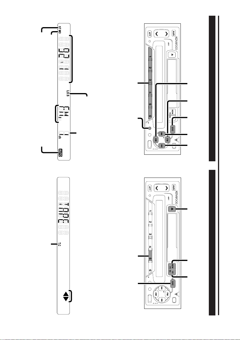
Tuner features
AUTO
AME
CLK
SRCT. C
FFREW
0
MONO
LOUD
Buttons and Display
ST indicat er
M ONO indicator
Frequency
— 5 —
Band display
AUTO indicat er
LO.S indicator
Preset Stat ion Number
Cassette player features
T.C indicator
Tape indicator
Page 6
Buttons and Display
AUTO
AME
CLK
4 ¢
u d
SRC/
PWR OFF
CLK AM#3#1
AUD FM
MONO
LOUD
Basic operations (See pa ge 4)
Other features
English
Clock display
Pow er
Turning on the power:
Press the SRC button.
NOTE
Turn the power on before carrying out th e following procedures.
Turning off the power:
Hold down the PW R OFF butto n for one se co nd or more.
Selecting the standby mode:
Press the SRC button rep eat ed ly to select to "OFF".
When "OFF" is displayed, the st andby mode is turned on .
The standby m od e turns all f u nc tions off although le aving the
unit’s power on. Use this mode when you want to have the
display illuminat ed bu t do not want to l isten to anythi ng.
Sw itching Modes
Switching Modes:
Each time you pre ss the SRC button, the mode switch es as
follows:
▼
Tuner mode
▼
Tap e mode
▼
Standby mode
NOTE
The mode switche s to the next mode from any mode which cannot b e u sed .
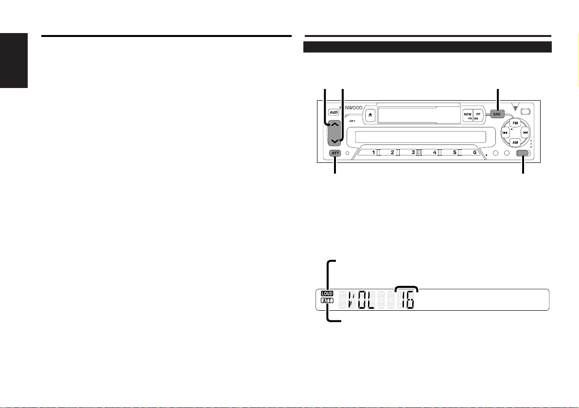
Volume
Increasing Volume:
Press the u button t o turn up the volu me.
Decreasing Volume:
Press the d button t o turn down t he vo lume.
— 6 —
Page 7

Basic operations (See pa ge 4)
Attenuator
This function allows you to turn down the volume quickly.
Turning Attenuator On/ Off:
Press the ATT button t o switch the attenuato r o n and off .
When the attenuato r is o n, the ATT indicator blinks.
When the attenuato r is o ff , the volu me returns to the original
level.
NOTE
Turning down the volume all the way turns off the attenuator
function.
Loudness
This function am plifies low and high t ones when the volume
is turned down.
The LOUD indicator lights up, when the loudness function is
on.
Turning Loudness On/Off:
Press the LOU D b utton to switch the loudne ss on and off.
Tuner features (See page 5)
Tuning
You can choose from three t uning modes: auto seek, local
seek, and manual.
When the AUTO indicator is off, manual tuning has been
selected, and when it is ON, auto seek tuning has been select ed.
Local seek refers to auto seek tuning that skips radio frequencies with poor reception. W hen local seek is on, the LO.S indicator turns on.
1
Press the SRC button rep eat ed ly un til tuner mode is ob tained.
"TUnE" is displayed w he n the tuner mode is se lec ted.
2
Press either the FM or AM but ton to select the band.
Each time you pre ss the FM butt o n, the band switches
between t he FM1, FM2 and FM3.
Press the AM button to select the MW and LW bands.
3
Each time you pre ss the AUTO butt on , the mode switch es as
follows:
▼ AUTO indicator LO.S indicator
Auto see k
▼
Local seek ❍ ❍
▼
Manual ✕ ✕
4
• Auto Seek Tuning
Press the
Press the
• Manual Tuning
Press the ¢ bu tt o n to increase the f r eq uen cy by on e step.
Press the
NOTE
The ST indicat or lig hts up when st e re o b roadcasts are being
received.
❍ ✕
¢ button to seek inc reasing frequencie s.
4 button to seek dec re asing frequencies.
4 button to decre ase t h e freque nc y b y o ne step.
— 7 —
Page 8

Tuner features (See page 5)
Monaural Reception
Turn monaural reception on and off.
Turning Monaural Reception On/ Off:
English
Hold down the MONO button o ne se con d or more to turn
monaural recept io n o n and off .
The M O NO in dic ato r l igh ts up when m o naural recept ion is on .
Station Preset M emory
Store the frequency of the station currently being listened to.
You can then recall that station with a single touch of a button.
1
Select t h e b and/ station that you want t o h ave stored.
2
Hold down the button (#1-6) that you want to u se for the station, for two se con ds or more.
The button number blinks on ce in the displ ay t o i nd icat e that
the d ata has been st o re d.
Recalling a Preset Station:
Press the prese t station button (#1-6) for the desir ed station.
The number of the recalled station is disp layed.
NOTE
You can store 6 stations in each of th e FM1, FM2, FM3, and AM
(MW and LW) bands.
Auto Memory Entry
You can automatically store all the receivable frequencies in
the band currently being listened to, and then recall them with
the touch of a button later. This function is especially useful
when you are travelling and do not know what stations are
available. Up to 6 frequencies can be stored t his way.
1
Select t h e b and for auto memory entry.
2
Hold down the AME butt o n for two sec on ds or more to start
auto m e mory en try.
The numbers o f the preset station buttons are shown in o rd er.
When all t h e s tations i n a certain band are sto re d in the pre se t
memory, the aut o memory en try stops. The t un er then plays
the last s tation re ce ive d.
Recalling a Preset Station:
Press the prese t station button (#1-6) for the desir ed station.
The number of the recalled station is disp layed.
NOTE
When the loc al seek function is turned whilst aut o memory entry
takes place, the aut o memory entry function is cancelled.
— 8 —
Page 9

Cassette player features (See page 5)
Playing Cassette Tapes
Loading and Playing Cassettes:
Load a cassette with the tape exposed on the right.
The tape starts playing auto matically.
With Side A f acing up, the
playing, and
The
2 3 indicator ligh ts up whilst play is paused.
Playing Cassettes Already Loaded:
Press the SRC button rep eat ed ly un til the t ape mode is
obtained. "TAPE" is displayed w he n the tape mo de has been
select ed .
Listening to the other side:
Press the FF butt o n and REW but ton at the sam e time.
Tap e p lay switches to the other side.
Stopping and Ejecting Cassettes:
Press the 0 bu tt o n.
The tape stops playing and t he cassette e jec ts.
NOTE
Remove a cassette f rom the unit wh en no t listening to it f or a
whilst. If y ou le ave it in the unit too long, the tape may st i ck to
the tape head and cause the unit to malfunction.
2 when Side B is playing.
3 indicator lights up when Side A is
Fast Forwarding and Rew inding Cassette Tapes
Fast Forwarding Tapes:
Press the FF butt o n.
If the REW butto n i s p res se d, n or mal tape play retu rns .
Rewinding Tapes:
Press the REW butto n.
If the FF butt o n i s p res se d, nor mal tape play retu rns .
Tuner Call Function
Switch automatically to the tuner whilst you are rewinding or
fast forwarding the tape.
Turning Tuner Call Function On/ Off:
Press the T.C button t o switch the tuner call f un ction on and
off.
The T.C indic ato r lig hts up when t h e tuner call f u nc tion is
turne d o n.
— 9 —
Page 10

Other features (See page 6)
Audio Control Setting
Adjust various parameters of sound quality.
1
English
Press the AUD bu tton t o en ter the control mode.
Each time the AUD button is press ed , the adjust ment mode
display changes as follows:
7 Bass 7 Treble 7 Balance 7 Fader 7 Volume
If you do no t move to step 2 in 5 sec on ds , the uni t will switch
back to the volume adjustment mode (i.e., t he no rmal m ode ).
NOTE
Source tone memory
Each s our ce (tape, FM, AM, and disc changer) has its own me mory in whic h to store the bass and treble tone se tt i ng s.
The settings made for a particular source are t he n r ecalled automatic ally whe nev er yo u u se that sou rce (e.g., FM mode uses the
tone settings made for FM, AM fo r A M, etc. ).
2
Press the
play.
Use t he following table as a guide for adjusting t h e settings in
each mode.
Adjust ment
mode
(Display)
Bass
(“BAS”)
Treble
(“TRE” )
Balance
(“BAL” )
Fad er
(“FAD”)
d/u butto ns to adjust the mode sho wn in t he di s-
Operation of Audio c ontrol bu tton
d button u button
Bass decreased.
Treble decreased.
Left channel empha-
sized.
Rear channel
increased.
Bass increased.
Treble increased.
Right channel empha-
sized.
Front channel
increased.
Clock Display
Display the time.
Switching to Time Display:
Press the CLK button repeated ly until the clock is dis played.
Adjusting Time
Adjust the time.
1
When the time is not displayed, first pr ess the CLK button to
display the time.
2
Hold down the CLK button for one secon d or more to enter the
Time Adjustment mode.
The hour display will blink.
3
• Adjusting the hours
Press the FM butt o n to advance the h ou rs, or pre ss the AM
button to make the ho urs go b ack.
• Adjusting the minutes
Press the
4 button to make the minutes go back.
4
Press the MENU butt o n to end the Tim e A dj us tment mode.
¢ button to advance the minutes, or pr es s the
— 10 —
Page 11

Other features (See page 6)
Theft Deterrent Faceplate
The faceplate of the unit can be detached and taken with you,
helping to deter theft.
Accessories
External view Number of items
1
..................... ..... .... ..... .... ...1
Projections
Grooves
Removing Faceplate:
Press the release butt on .
The faceplate is unlocked , allowin g y ou to detach it.
NOTE
• The faceplate is a precision p iec e o f equipment and can be
damaged by shocks or jo lts. For t hat re ason, keep the faceplate
in its spe cial storage case w h ilst detached.
• Do not expo se the faceplate or its st or age case to dire ct sun-
light o r e xc ess ive h eat or hu midity. Also avoid places with too
much du st or the poss ibi lity of wat er s plashing.
Reattaching Faceplate:
1
Align t he p roje ctions o n the un it wi th the grooves on the faceplate.
2
Push the faceplate in until it c lick s.
The faceplate is locked in pl ace, allowing you to use the unit.
Release button
2
3
4
2CAUTION
The use of any accessories except for those provid ed might result
in damage to the uni t. Make sure o nly to use the accessories
shipped wi th the unit, as shown above.
..................... ..... .... ..... .... ...2
..................... ..... .... ..... .... ...1
..................... ..... .... ..... .... ...1
— 11 —
Page 12

Installation Procedure
1. To prevent short circuits, remove the key from the ignition and
disconnect the
2. Make the proper input and output cable connections for each unit.
3. Connect the cable on the wiring harness.
4. Take Connector B on the wiring harness and connect it to the
English
speaker connector in your vehicle.
5. Take Connector A on the wiring harness and connect it to the
external power connector on your vehicle.
6. Connect the wiring harness connector to the unit.
7. Install the unit in your car.
8. Reconnect the
9. Press the reset button.
- terminal of the battery.
- terminal of the battery.
2CAUTION
• If your car is not prepared fo r this sp eci al connection-syst em,
consult y ou r k en wood dealer.
• Only us e ant en na conversio n adapters (ISO-JASO ) when the
antenna cord has an ISO p lug .
• Make sure that all cable connections are securely made by
insert ing jacks until they lock co mpletely.
• If your vehic le's ig nition do es no t have an ACC p osi tion, or if
the ig nition cable is con ne cted to a power sou rce with c on stant
voltage such as a battery cable, the power will not be linke d
wit h the igni tion (i.e., it will not turn on and off along with the
ignitio n). If yo u want t o link the uni t's power with t h e ig ni tion,
connect the ig nition cable to a power sourc e that can be turned
on and off with the ignition key.
• If t he fuse blo ws, firs t make sure th at the cables have not
caused a short circuit, t h en re place the old fuse with one with
the same rating.
• Do not let unconn ected cables or terminals touc h metal on the
car or anything else cond uc ting elec tricity. To prevent short circuits, also do not remove the caps on the ends of the unconnecte d c ables or the terminals.
• Connect the sp eaker cables correctly to t h e terminals to which
they c or res po nd. The unit may receive damage or f ail t o work if
you share the
the car.
• Aft er the unit is installed, check whethe r the brake lamps , in di-
cators, wip ers , e tc. on the car are working pro pe rly.
• Some d is c c hangers nee d c onv er sio n c ables for connection.
See the section on "Safety Precautions" for details.
• Insulate u nco nn ec ted cables with viny l tape or other similar
mate rial.
- cables and/or ground them t o any metal part in
— 12 —
Page 13

Connecting Cables to Terminals
P.CONT.OUT
1234567
8
1234567
8
Fuse
Antenn a Conversion Adaptor (ISO–JASO) (Accessory
Antenn a Cord (ISO)
Connector Function Guide
Pin Numbers for
ISO Connectors
External Power
Connector
A–4
A–5
A–7
A–8
Speaker
Connector
B–1
B–2
B–3
B–4
B–5
B–6
B–7
B–8
Cable Colour Functions
Yellow
Blue/White
Red
Black
Battery
Power Control
Ignition (ACC)
Earth (Ground)
Connection
Purple
Purple/Black
Gray
Gray/Black
White
White/Black
Green
Green/Black
Rear Right (+)
Rear Right (–)
Front Right (+)
Front Right (–)
Front Left (+)
Front Left (–)
Rear Left (+)
Rear Left (–)
4)
FM/AM antenna input
Connector A
Connector B
Wiring harness
(Accessory
Battery cable (Yellow)
Ignition cable (Red)
A–4 Pin (Yellow)
1)
A–7 Pin (Red)
If no co nne ctions are m ade, do
not let t h e c able come out from
the tab.
Power control/ Motor antenna
control cable (Blue/White)
Connect either t o the powe r
control terminal w h en usi ng
the optional power amp lifier,
or to the antenn a control te rminal in t h e v ehi cle .
— 13 —
Page 14

2WARNIN G
Connecting the ISO Connector (see p.13)
The pin arrang ement for t h e I SO connectors de pe nds o n the type
of veh icl e y ou dr ive . Make sure to make t he pro pe r c on nec tions to
prevent dam age to t he un it.
The default con ne ction for the wi ring h arness is des cri be d in
English
below. If the ISO connector pins are set as described in 2 or 3,
make t h e c on nec tion as illustrated.
1 (Default sett ing ) The A-7 pin (red) of the vehicle 's ISO connec-
tor is link ed with the ign ition, and the A-4 pin (yellow) is connecte d to the constant po wer supply.
Unit Vehicle
Ignition cable (Red)
Battery cable (Yellow)
A–7 Pin (Red)
A–4 Pin (Yellow)
2 The A-7 pin (red) of t he ve hic le's ISO connector is co nn ec ted to
the co ns tant power supply, and t h e A-4 pin (yellow) is linked to
the ig nition.
Unit Vehicle
Ignition cable (Red)
Battery cable (Yellow)
A–7 Pin (Red)
A–4 Pin (Yellow)
3 The A-4 pin (yellow) of the vehi cle 's I SO connector is n ot con-
necte d to anyt hin g, while t he A-7 pin (red) is connect e d to the
const ant po wer supply (or bot h the A-7 (red) an d A -4 (yellow)
pins are connect e d to the constant po wer supply).
Unit Vehicle
Ignition cable (Red)
A–7 Pin (Red)
1
InstallationConnecting Cables to Terminals
■
Installation
Firewall or metal support
Accessory3
Bend the tabs of the
mounting sleeve with
a screwdriver or simi-
Self-tapping
screw
(commercially available)
NOTE
Metal mounting
strap
(commercially
available)
Make sure t hat the un it is installed securely in place. If t he u nit is
unstable, it may malfunction (eg, t h e s ou nd may skip).
lar utensil and attach
it in place.
Battery cable (Yellow)
NOTE
When the con ne ction is made as in
3 above, the un it's power will
A–4 Pin (Yellow)
not b e li nke d to the ignition key. For that reason, always make sure
to turn off th e u nit's power when the ignition is turned o ff.
To link the unit's power t o the ign ition, co nn ect the ignition cable
(ACC...red) to a pow e r so ur ce that can be turned on and off with
the ig nition ke y.
— 14 —
Page 15

Installation
■
Removing the hard rubber frame
1
Engage the catch pins on the removal t oo l and remove the two
locks on the lower level.
Lower the frame and pull it f or ward as shown in the figure.
Lock
Catch
■
Removing the Unit
1
Refer t o the section “ Removing the hard rubber frame” and
then remove the hard rubber frame.
2
Remove the Hex-head screw with integral washer (M4
the b ack panel.
3
Insert the two r emoval t oo ls d ee ply in to the slots on each side,
as shown.
×8) on
Accessory2
Removal tool
2
When the lower level is removed , r emove the up per two lo cations.
NOTE
The frame can be removed from t h e top side in the sam e manner.
— 15 —
Accessory3
4
Lower the removal too l
toward the bott om, and pull
out the uni t halfway wh ilst
pressing towards t h e
inside.
2CAUTION
Be careful to avoid injury from th e cat ch pin s o n the re moval to ol.
5
Pull the unit all the way out
wit h yo ur hands, being careful no t to drop it.
Catch facing up
Page 16

Troubleshooting Guide
What m ight appear to be a m alfunction in your unit may just be t he result of slight misoperation or misw iring. Before
calling service, first check t he following table for possible problems.
SOLUTIONPOSSIBLE CAUSEPROBLEM
The pow e r do es no t t ur n o n. The fuse has blown. After checking for short circuits in the cables, replace the
English
No ACC position on vehicle ig nition. Connect t h e s am e c able to the ig nition as th e b attery cable.
No sound can be heard, or t he
volume is low .
Nothing happens when the b uttons are pressed.
The sound quality is poor o r d istorted.
Radio reception is poor. The car antenna is not exte nde d. Pull out t he ant en na all the way.
The mem o ry is e rased whe n
the igni tion is turned off.
The Att enu ato r function is turned on. Turn off the Atte nuat or function.
The fader and/or balance settings are set all the way t o
one side.
The input/output c ables or wiring harness are connected
incorrect ly .
The cassette tape is bad. Try playing another cassett e tape. If n o p rob lem is exp eri-
The cassette tape is not l oaded prope rly. If the t ape does no t st art to play when a cassette t ape is
The computer chip in the unit is not fu nctioning n ormally. Press the reset button on the unit (see page 3).
The tape head is dirty. Clean the tape head, referr ing to t h e sec tion on "Cleaning
A speaker cable may be pinched by a screw in the car. Check the speaker wiring .
The speakers are not wired correc tly. Reconnect the speaker cables so t hat each output terminal
The antenna control cable is not connected. Connect t h e c able correctly, referring to t he se ction on
The battery cable has not b een c onn ec ted to the pr op er
terminal.
The ignition and battery cable are incorrectly co nne cted. Connect t h e c able correctly, referring to t he se ction on
fuse with one having the same rat ing .
Reset t he fader and/or balance settings.
Reconnect the input/out pu t cables and/or the w iring harness
correctl y. See the section on "Connecting Cables to
Terminals".
enced, t he first tape was bad.
inserted , e jec t it and try inserting it again.
the tape head" (see page 3).
is connected to a dif ferent speaker.
"Conn ec ting Cables to Termi nals".
Connect t h e c able correctly, referring to t he se ction on
"Conn ec ting Cables to Termi nals".
"Conn ec ting Cables to Termi nals".
— 16 —
Page 17

Specifications
Specifications subject to change wit hout notice.
FM tuner section
Frequency range (50 kHz Space) ..............87.5 MHz – 108.0 MHz
Usable sensitiv ity (S/N = 26dB ) ............... .... ..... .... ..... . 0. 7 µ V/75 Ω
Quiet ing Sensitivit y (S/N = 4 6dB ).... ..... .... ..... .... ..... .... . 1.6 µ V/75 Ω
Frequency response (±3.0 dB) ........................ .... .. 30 H z – 15 kHz
Signal to Noise ratio (MONO) ................... .... ..... .... ..... .... .....65 dB
Selectivity (DIN) (± 400 kH z) .......................... .... ..... .... ..... ≥ 80 dB
Stereo separation (1 kHz) ............................... ..... .... ..... .... ...35 dB
MW tuner section
Frequency range (9 kHz Space).. ..... .... ..... .... .. 53 1 k Hz – 1611 kHz
Usable sensitiv ity (S/N = 20dB ) ................ ..... .... ..... .... ..... .... . 2 5 µ V
LW tuner section
Frequency range ....... .... ..... .... ..... .... ..... .... ..... ...153 kHz – 281 kHz
Usable sensitiv ity (S/N = 20dB).................. ..... .... ..... .... ..... ...45 µV
Cassette player section
Tap e s pee d .... ..... .... ..... .... .... ..... .... ..... .... ..... .... ..... ....4.76 cm/sec.
Wow & Flutter (W RMS) ................. .... ..... .... ..... .... ..... .... ....0,12 %
Frequency respons (120 µs) .......... ..... .... ... 30 H z – 14 kHz (±3 dB)
Separation (1 kHz) ..... .... ..... .... ..... .... ..... .... ..... .... ..... .... ..... .... .40 dB
Signal to Noise ratio ................................. ..... .... ..... .... ..... ....54 dB
Audio section
Maximum output powe r............. .... ..... .... ..... .... ..... .... ..... . 3 0 W × 4
Outpu t power (DIN 45324, +B=14.4 V) .......................... 20 W × 4
Tone action
Bass:............. .... ..... .... ..... .... ..... .... ..... .... ..... ..100 Hz ± 1 0 dB
Treble:.......... ..... .... ..... .... ..... .... ..... .... .... ..... ...10 kHz ±10 dB
General
Operating voltage .................... ..... .... . 14 .4 V (11 – 16 V allowable)
Current consumption .................. ..... .... ..... ....10 A at Rated power
Installation size (W × H × D ) .. .... ..... .... ..... .... .... 1 82 × 53 × 15 4 mm
Weig ht.... ..... .... ..... .... ..... .... ..... .... ..... .... ..... .... .... ..... .... ..... ....1400 g
— 17 —
Page 18

documentation manual, user maintenance, brochure, user reference, pdf manual
This file has been downloaded from:
User Manual and User Guide for many equipments like mobile phones, photo cameras, monther board, monitors, software, tv, dvd, and othes..
Manual users, user manuals, user guide manual, owners manual, instruction manual, manual owner, manual owner's, manual guide,
manual operation, operating manual, user's manual, operating instructions, manual operators, manual operator, manual product,
 Loading...