

Kenwood KR-897, KR-797 User Manual
KENWOOD
AUDIO VIDEO SURROUND RECEIVER
KR-897
KR-797
INSTRUCTION MANUAL
KENWOOD CORPORATION
This manual contains instructions for two models. Model availability and features 1(functions) may differ depending on country and sales area.
Model KR-897 is not available in except for U.S.A. and Canada. I
B60-3069-00 (_) (K, P, Y) i-.l_-C.'i
98/1211 1098765432 1 97"/12 11 109
KR-B97/KR-797 I1En)
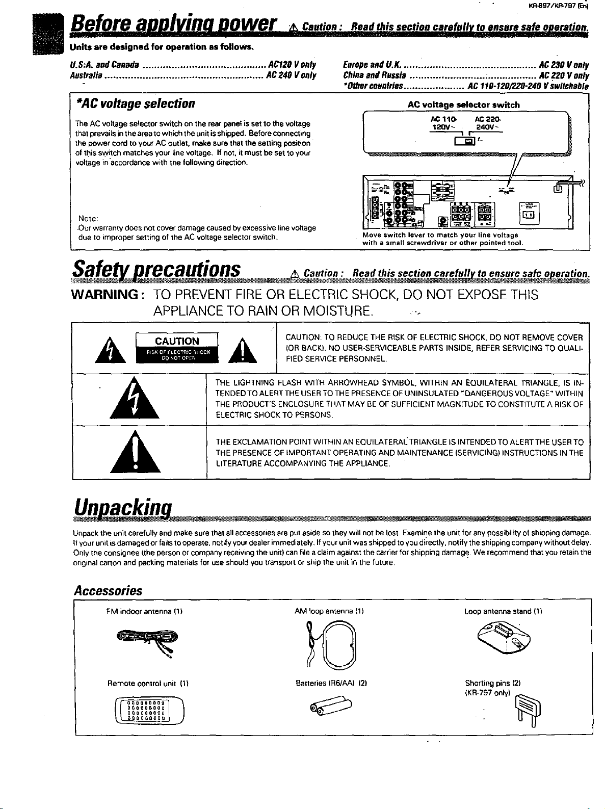
I B..eforeauulvinonewer o.,o.: ensure safe operat#p .
Units are designed for operation as follows,
U.S:A. and Canada ........................................... AC120 V only Europe and UoK. .............................................. AC 230 Vonly
Australia ....................................................... AC240 V only China and Russia .......................... :................. AC220 V only
*AC voltage selection
The AC voltage selector switch oe the rear panel is set to the voltage
that prevailsin the areato which the unit is shipped, Beforeconnecting
the power cord to your AC outlet, make surethat the setting position
of this switch matches your linevoltage, If not. it must be set toyour
voltage inaccordance with the renewing direction.
Note:
•Our warranty does not cover damage caused by excessive line voltage
due to improper setting of the AC voltage selector switch.
•Other countries ..................... AC 110-120/22.0-240 V switchable
AC voltage selector switch
Move switch lever to match your line voltage
with a smart screwdriver or other pointed tool,
recautions Oantioa Read this section carefull to ensure safe o eratioa
WARNING : TO PREVENT FIRE OR ELECTRICSHOCK, DO NOT EXPOSETHIS
APPLIANCE TO RAIN OR MOISTURE. ._
CAUTION: TO REDUCE THE RISK OF ELECTRIC SHOCK. DO NOT REMOVE COVER
A c,uT,o.
I k THE LIGHTNING FLASH WITH ARROWHEAD SYMBOL, WITHIN AN EQUILATERAL TRIANGLE. IS IN-
._ THE PRODUCT'S ENCLOSURE THAT MAY BE OF SUFFICIENT MAGNITUDE TO CONSTITUTE A RISK OF
p_*]_l[*ltl=,J1
TENDED TO ALERT THE USERTO THE PRESENCE OF UNINSULATED ,DANGEROUS VOLTAGE" WITHIN
ELECTRIC SHOCK TO PERSONS•
THE EXCLAMATION POINTWITHIN AN EQUILATERAI_ TRIANGLE IS INTENDED TO ALERT THE USER TO
(OR BACK)• NO USER-SERVICEABLE PARTS INSIDE. REFER SERVICING TO QUALI-
FIED SERVICE PERSONNEL,
Unacki - _. . -.-
Unpack the unit carefullyand make sure that all accessoriesare put aside so .,heywill not be lost. Examine the unit for any possibilityof shipping damage.
if your unit isdamaged or fails tooperate, notify your pealer immediately. If your unit was shipped to you directly, notify the shipping company without delay.
Only the consignee (the person or company receiving the unit) can file aclaimagainst the carrier for shipping damage. We recommend thatyou retain the
original carton and packing materials for use should youtransport or ship the unit in the future.
Accessories
FM indoor antenna {1)
AM loop antenna (1)
Loop antenna stand (1)
Remote control unit 11)
oo0000o0_
OQOSQO088
_O_Q__OGOOOgO00
Batteries (R6/AA) 121
Shorting pins (2)
(KR-797 only)
--
Y.R_97/KR-797 (En]
Suecialfeatures.............,
DOLBYPROL,QG!C,&OOLBY3 STEREO
The surround system reproducus eideo software programs carrying the I'1r1[_ mark with similar acoustic effects to movie
theaters.
The DOIJ_Y PRO LOGIC mode controls the audio signals of the Front Left/Rigid, Center and Rear surround channels using the built-in
diroctivity enhancer cercuit to reproduce the feeling of sound motions very realistically.
TheDOLB Y3 STEREO mode can reproduce the motions ofsoundeven when oulythu frontand center speakers are used,byproviding proper
acoustic position using the diroctivity enhancer circuit,
SRS 3D Stereo .........
The SRS (Sound Retrieval System) is an innovative system simulating a 3-dimensioual sound space, which features clearly improved
feelings ofdepth, sound field extension and acoustic image positioning as well as e widened listening area.
..... r II
Contents Oautio. : Read the pages marked _ carefully to
Before applying power .............................................................................................................................................................................................2
,_ Beforeapplyingpower.........................................................................................................................................2
z_ Safetyprecautions...............................................................................................................................................2
Special features .........................................................................................................................................................................................................3
Systemconnection ....................................................................................................................................................................................................4
: :ConnectionsofAudio andVideocomponents(KR-897) ....................................................4
° Connectionsof Audioand Videocomponents(KR-797)......................................................................................5
About thesystemcontrolconnections.................................................................................................................6
Connectionof speakers(KR-897)........................................................................................................................7
Connectionof speakers(KR-797)........................................................................................................................8
Connectionof antenna.........................................................................................................................................9
FM OE-EMPHASIS/ CHANNELSPACEswitch ........................................................... I0
Controlsand indicators .........................................................................................................................................................................................11
Operationof remote control unit ..........................................................................................................................:................................................12
Playingmusic ...........................................................................................................................................................................................................14
Sound adjustment functions ..................................................................................................................................................................................15
Recordin.............................................................................L......................................................................................................................................18
Broadcast receptiong ..............................................................................................................................................................................................19
Receivingbroadcaststations ....................................................................................._......................................19
Receivingradiostations byspecifyingits frequency.........................................................................................20
Storingradio stationsin memory(Stationpreset) ........................................... 21
Receivingapreset station...........................................:.....................................................................................21
Receivingall presetstationsin order(P.CALL)..................................................................................................21
Presence play .......................................................................................................................................................................:..................................23
Adjustmentsfor surroundplay..........................................................................................................................24
Surroundplay .....................................................................................................................................................26
SRS30 Stereo(SoundRetrievalSystem)..........................................................................................................27
In case of difficulty ...................................................=..........................................................................................................................:...................28
z_ Specifications ...........................................................................................................................................................................................................30
ensure safe operation.
_ .- _ . -.
KP.897/KR*797 IEn]
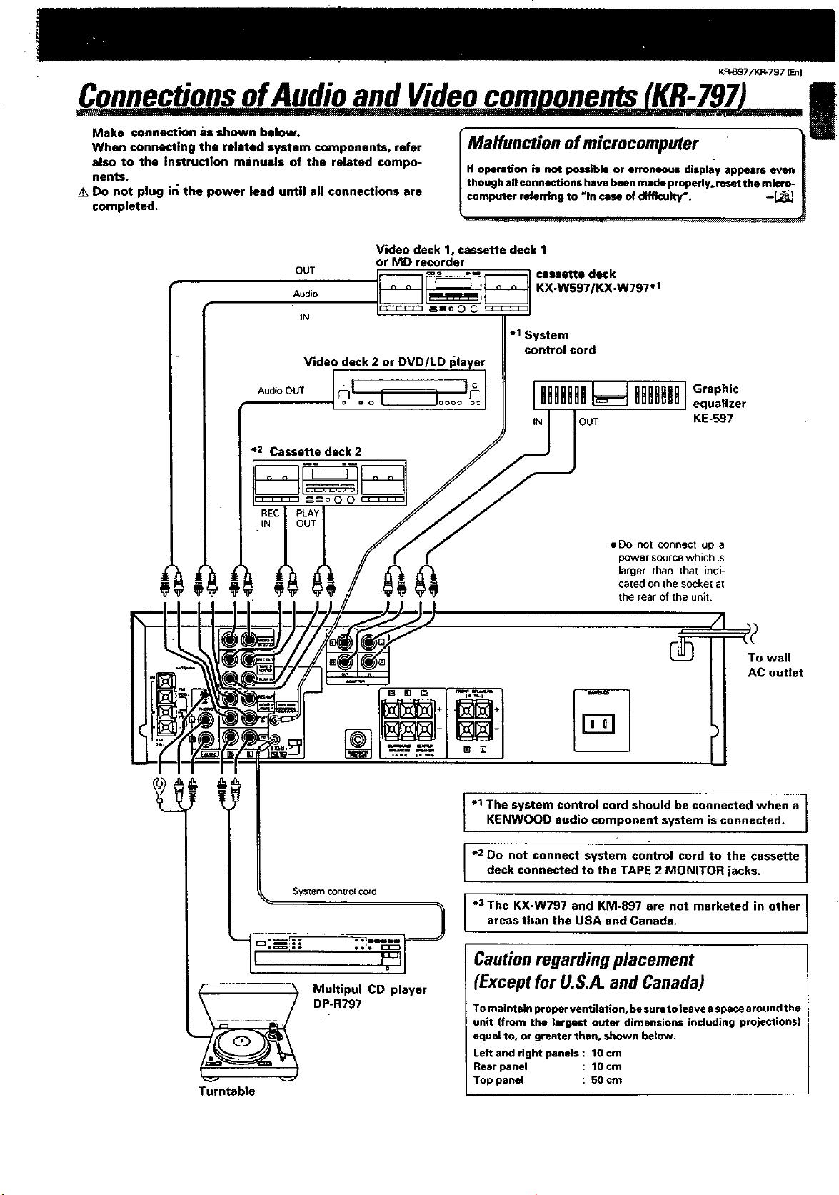
C nnectionsofAudio and Videocorn onents KR-B97
Make connection as shown below.
When connecting the related system components, refer
also to the instruction manuals of the related compo-
nents.
Do not plug in the power lead until all connections are
completed.
Cassette deck 1, MD recorder
or VCR 1
__1_ Cassette deck
Video deck 2 or DVD/LD player
*2 Cassettedeck2
l Malfunction ofmicrocomputer !
if operation is not possible or erroneous display appears even
thoughall connections have beenmade properly, reset the micro- |
computer referring to "In case of difficulty'. -_ [
I__l KX'WS971KX'W797"3
=-=o o o c_:_ I
.I System
control cord
Power amplifier
KM.897-3
OO
• System control cord
To wall
AC outlet
• Do not connect up a power source which is
larger than that indicated on the socket at the
rear of the unit.
Turntable
M;! tR7P;71CDplayer
The system control cord should be connected when a
I" }
KI=NWOOD audio component system is connected.
e2 Do not connect system control cord to the cassette 1
deck connected to the TAPE 2 MONITOR jacks.
*3 The KX-W797 and KM-897 are not marketed in other
areas than the USA and Canada.
/
_7/K_797 JEt
ConnectionsofAudioandVideocomuonents(KR-797)
Make connection as shown below.
When connecting the related system components, refer
also to the instruction manuals of the related compo-
nents.
/k Do not plug in the power lead until all connections are
completed.
Video deck 1, cassette deck 1
OUT
Audio
IN
Video deck 2 or DVD/LD I_layer
*2 Cassette deck 2
or MD recorder
I Malfunction of microcomputer .
If operation is not possible or erroneous display appears even
though allconnections have been made properly, reset the micro-
computer referring to "In case of difficulty'. -[_.
KX-W597/KX-W797 .1
-1 System
control cord
!
System control cord
• Do not connect up a
power sourcewhich is
larger than that indi-
cated on the socket at
the rear of the unit.
%
-1 The system control cord should be connected when a
KENWOOD aud o component system is connected.
*2 Do not connect system control cord to the cassette I
I deck connected to the TAPE 2 MONITOR jacks, t
*3 The KX-W797 and KM-897 are not marketed in other I
areas than the USA and Canada.
I
Turntable
Multipul CD player
DP-R797
Cautionregarding placement
(Except for U.S.A.and Canada)
To maintain proper ventilation, be sure to leave a space around the
unit (from the largest outer dimensions including projections)
equal to, or greater than, shown below.
Left and right panels : 10 cm
Rear panel : 1Ocm
Top panel : 50 cm
K/3897/KR-797 ten)
I
I
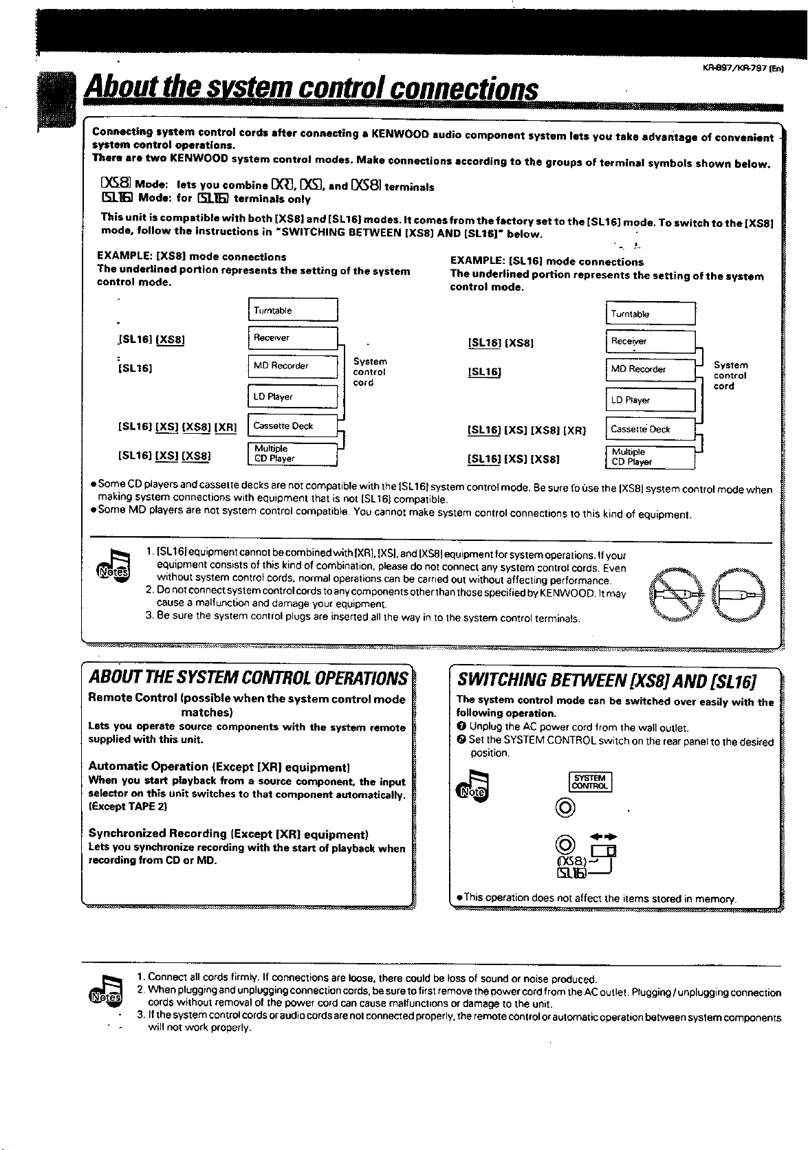
Connecting system control cords after connecting a KENWOOO audio component system lets you take advantage of convenient
system control operations.
There ere two KENWOOO system €ontrol modes. Make connections according to the groups of terminal symbols shown below.
[_ Mode: lets you combine [X_, _f_], and [_8] terminals
I%'J_] Mode: for [t;l_] terminals only
This unit is compntible with both iXSS] and [SLIE) modes. It comes from the factory set to the [SL16] mode. To switch to the [XS8]
mode, follow the instructions in *SWITCHING BETWEEN [XS8] AND [SL16]" below.
EXAMPLE: iXS8] mode connections
The uncle€tined portion rep;esents the setting of the system
control mode.
Turntable
JSL161 (XS8] [ Receiver
:[SLt 6] I MDRec°rder I Systemcontrol
cord
I LD PlaYer I
teL16] [XS] [XS8] [XR] [ Cassette Deck
[SL16] [XS] [XS8} I MultipleGD Player I
• Some CD players andcassette decks are not compatible with the [SL161 system controlmode. Be sure fo 0se the IXS8] system controlmode when
making system connections with equipment that isnot ISLtC) compatible,
• Some MD players are not system control compatible• You cannot make system control connections to this kind of equipment.
EXAMPLE: [eL16] mode connections
The under|ined portion represents the setting of the system
control mode.
[SL16] [XS8] I
[SL161
teLl6] [XS] [XS8] [XR] LcassetteDeck
[SL161 [XS] [XS8] I CDBayer
)
ITumtable
1
Receiver
IMD Recorder System
I
I LDPlayer
I Muaiple
control
cord
1.|eLI 6_equipment cannotbe combined with |XRL |XS|.and IXSS_equipment for system operaryans._fyou[
equipment consistsof this kind of combination, please do not connect any system control cords. Even
without system control cords, normal operations can be earnedout without affecting performance.
2. Do not connectsystem controlcords to anycomponentsother thanthose specified by KENWOOD Itmay
cause a malfunction and damage your equipment.
3. Be sure the system control plugs are inserted all the way in to the system control terminals,
ABOUT THESYSTEM CONTROLOPERATIONS
Remote Control (possible when the system control mode
matches)
Lets you operate source components with the system remote
supplied with this unit.
Automatic Operation (Except [XR] equipment)
When you start p|ayback from a source component, the input
selector on this unit switches to that component automatically.
(Except TAPE 2)
Synchronized Recording (Except [XR| equipment)
Lets you synchronize recording with the start of playback when
recording from CD or MD.
SWITCHING BETWEEN [XS8] AND [SL16]
The system control mode can be switched over easily with the
following operation,
I_ Unplug the AC power cord from the wall outlet,
(_ Set the SYSTEM CONTROL switch on the rear panel to the desired
position.
(DG_)-' I
• This operation does not affect the items storedin memory.
i_ 1.Connect allcords firmly, If connections are loose, there couldbe loss of sound or noise produced.
2. When plugging andunplugging connection cords,be sure to first remove the power cord from the AC outlet• Plugging/unplugging connection
cordswithout removal of the 9owe_ cord cancause matfunctv3ns o_damage to the unit.
3. If the system control cordsor audiocordsarenot connected properly, the remote controlor automatic operation between system components
will not work properly.
KR-Sg7/KR=797 (En}
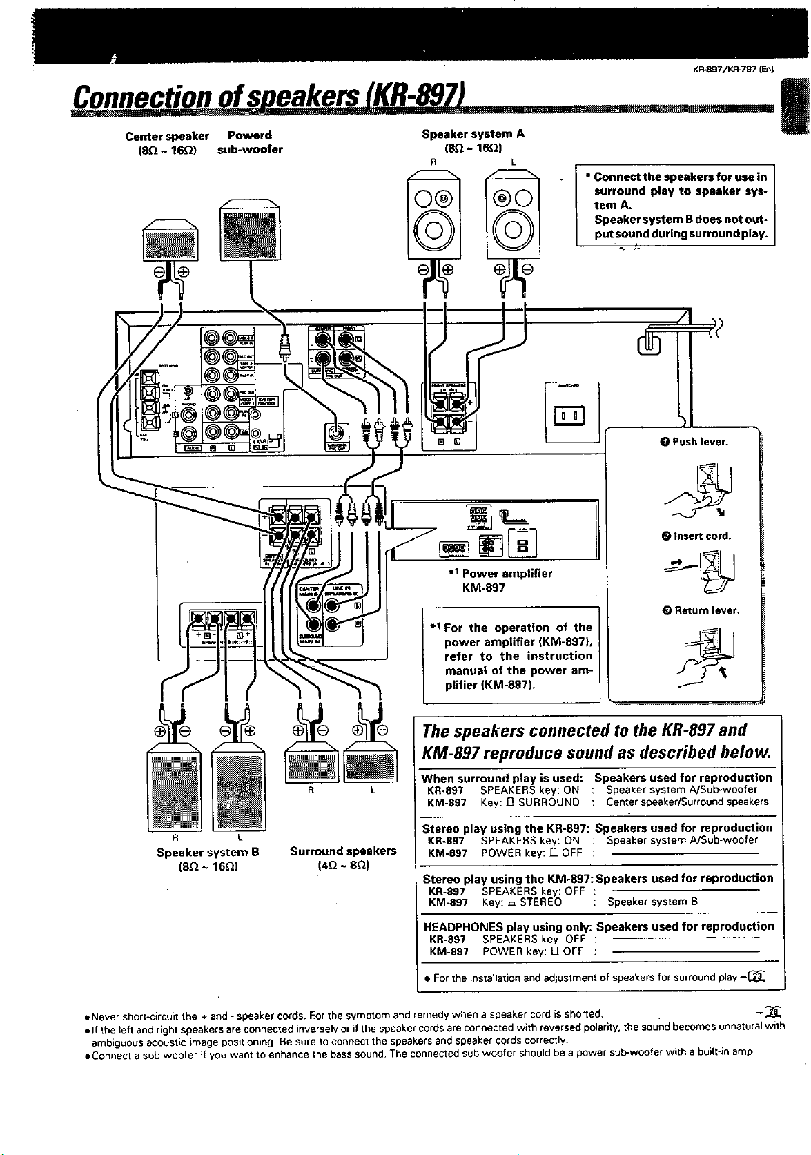
Connectionofs eakers KR-897 I
Center speaker Powerd
(SQ ~ 16_) sub-woofer
Speaker system A
(8.Q~ 16Q)
surround play to speaker sys-
tem A.
Speaker system B does not out-
• I *Connectthespeakersforusein
putsound during surround play.
i
°. _.
%
O Push lever.
Speaker system B
(8_ ~ 16_)
R L
Surround speakers
(4_ ~ 8Q)
O Insert cord.
.1 Power amplifier
KM-897
(_ Return lever.
.1 For the operation of the
power amplifier (KM-897),
refer to the instruction
manual of the power am-
plifier (KM-897).
The speakers connected to the KR-897 and
KM-897 reproduce sound as described below.
When surround play is used: Speakers used for reproduction
KR-897 SPEAKERS key: ON : Speaker system A/Sub-woofer
KM-897 Key: J_ SURROUND : Center speaker/Surround speakers
Stereo play using the KR-897: Speakers used for reproduction
KR-897 SPEAKERS key: ON : Speaker system A/Sub-woofer
KM-897 POWER key: ["1OFF ;
Stereo play using the KM-897: Speakers used for reproduction
KR-897 SPEAKERS key: OFF :
KM-897 Key: _ STEREO : Speaker system B
HEADPHONES play using only: Speakers used for reproduction
KR-897 SPEAKERS key: OFF :
KM-897 POWER key: 17 OFF :
• For the installation and adjustment of speakers for surroundplay -_
• Never short-circuit the + and - speaker cords. Eor the symptom and remedy when a speaker cord is shorted. -_
• If the left and right speakers areconnected inversely or if the speakercords are connected with reversed pelarity, the soundbecomes unnatural with
ambiguous acoustic image positioning. Be sure to connect the speakers and speaker cords correctly.
eConnect a sub woofer if you want to enhance the bass sound The connected sub-woofer should be a power sub-woofer with a built-in amp
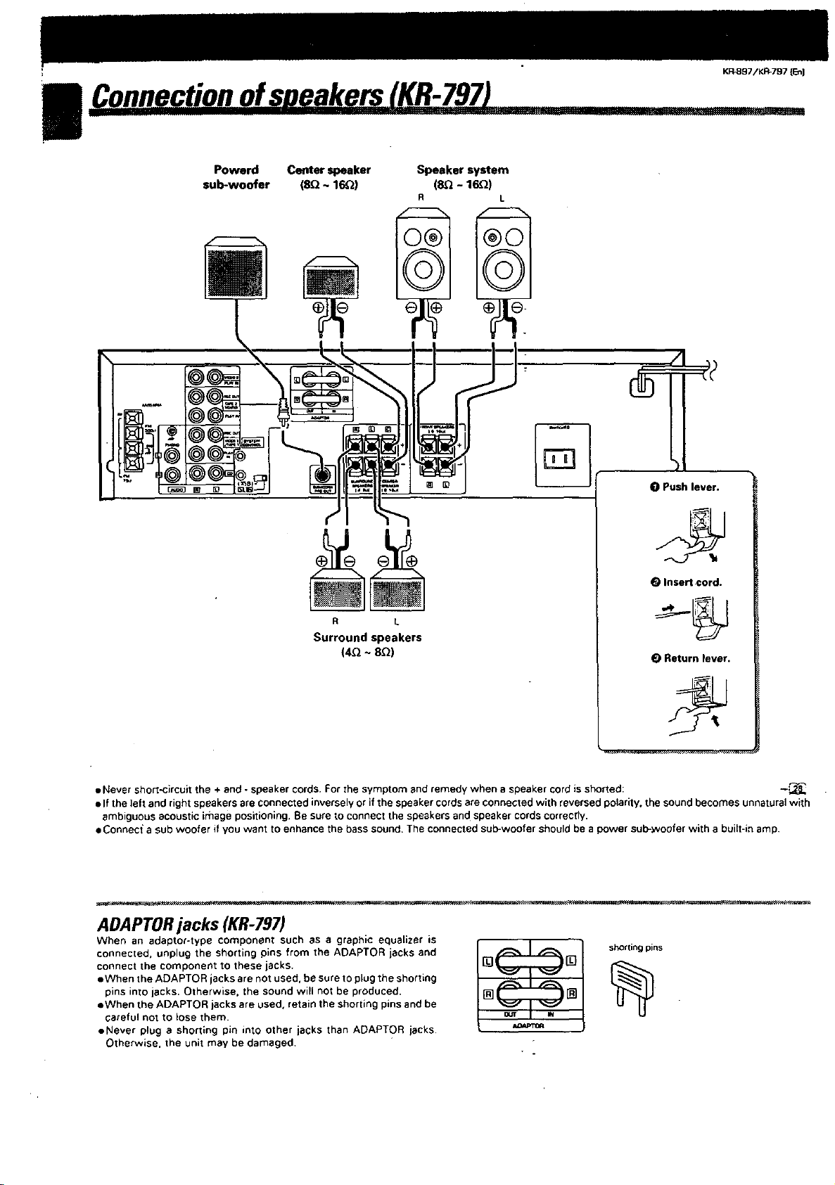
€onnection ofspqakersr_ ,
Powerd Center speaker Speaker system
sub-woofer (8Q ~ 16_) (SQ - 16Q)
KR_97/KP,-797 {En)
0 Push lever.
0 Insert cord.
R L
Surround speakers
(4_ ~ 8_)
• Never short-circuit the + end - speaker cords. For the symptom and remedy when a speaker cord is shorted: -_
elf the left and rightspeakers are connected inversely or if the speaker cords are connected with reversed polarity, the sound becomes unnatural with
ambiguous acoustic image positioning. Be sure to connect the speakers and speaker cords correctly.
eConnec_ a sub woofer if you want to enhance the bass sound. The connected sub-woofer should be a power sub-_Nooferwith a built-in amp.
0 Return lever.
ADAPTORjacks (KR-797)
connect the component to these jacks. [] []
eWhen the ADAPTOR jacks are not used, be sure to plug the shorting
pins into jacks. Otherwise. the sound will not be produced. [] []
When an adaptor-type component such as a graph;c equalizer is J1
eWhen the ADAPTOR jacksare used. retain the shorting pins and be
careful not to lose them.
eNever plug a shorting pin into other jacks than ADAPTOR jacks.
Otherwise. the unit may be damaged,
KR.897iKR-797 {L_)
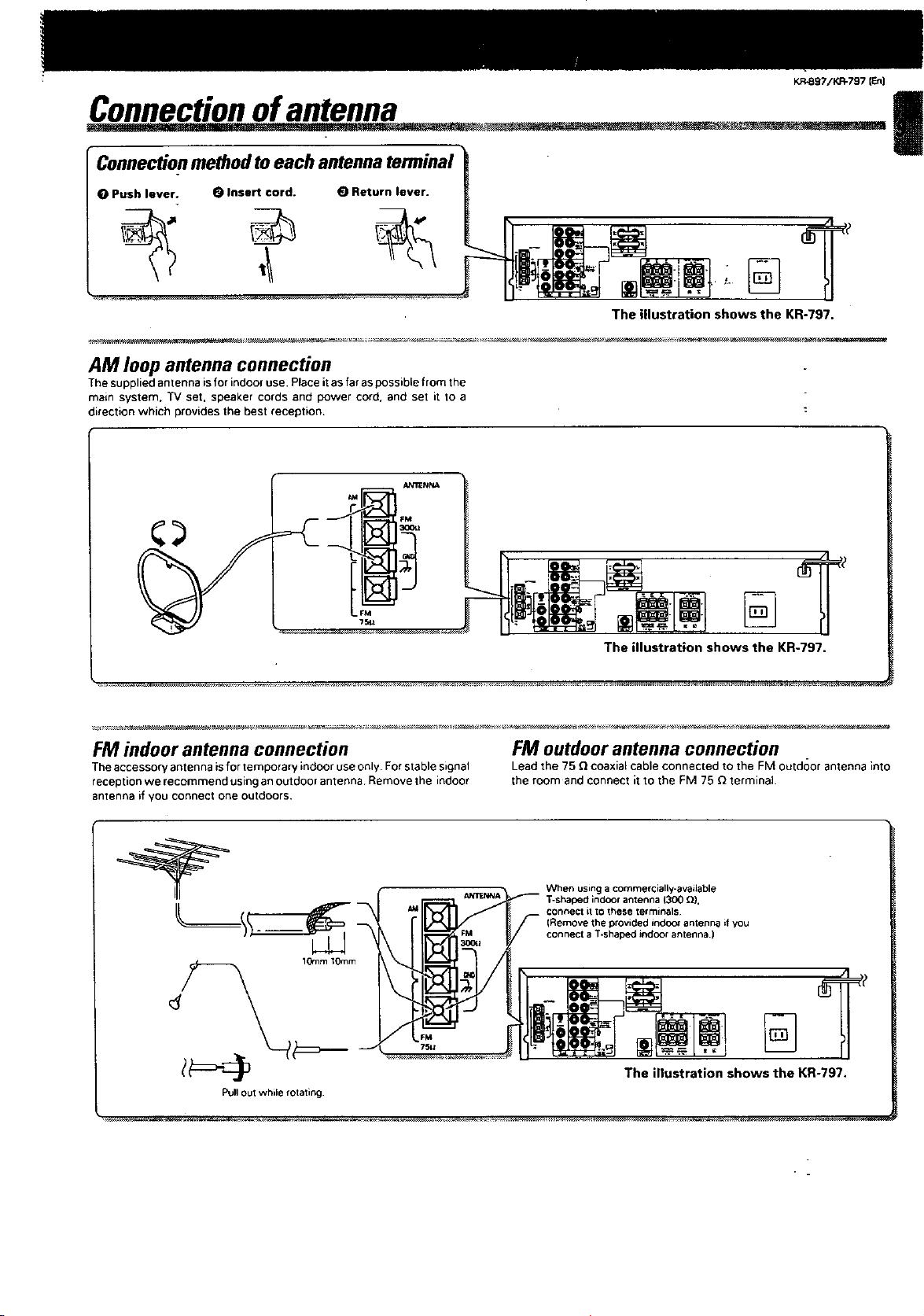
Connectionof_antenna I
Connectionmethodtoeach antennaterminal
O Push lever. O Insert cord. (_ Return lever.
The illustration shows the KR-797.
AM loop antenna connection
The supplied antenna is for indoor use. Place it as far as possible from the
main system. TV set, speaker cords and power cord. and set _t 1o a
direction which provides the best reception.
FM indoor antenna connection
The accessory antenna isfor temporary indoor use only. For stable signal
reception we recommend using an outdoor antenna Remove the indoor
antenna if you connect one outdoors.
1GramIOmm
Pug OUtwhi_e rota_ing_
The illustration shows the KR-797.
FM outdoor antenna connection
Lead the 75 _ coaxial cable connected to the FM outdoor antenna into
the room and connect it to the FM 75 _ terminal•
When usinga commercially-available
connect itto these terminals
(Remove the provided indoor antenr_ if you
connect a T-shapedindoor antenna.)
1300 _).
The illustration shows the KR-797.
|
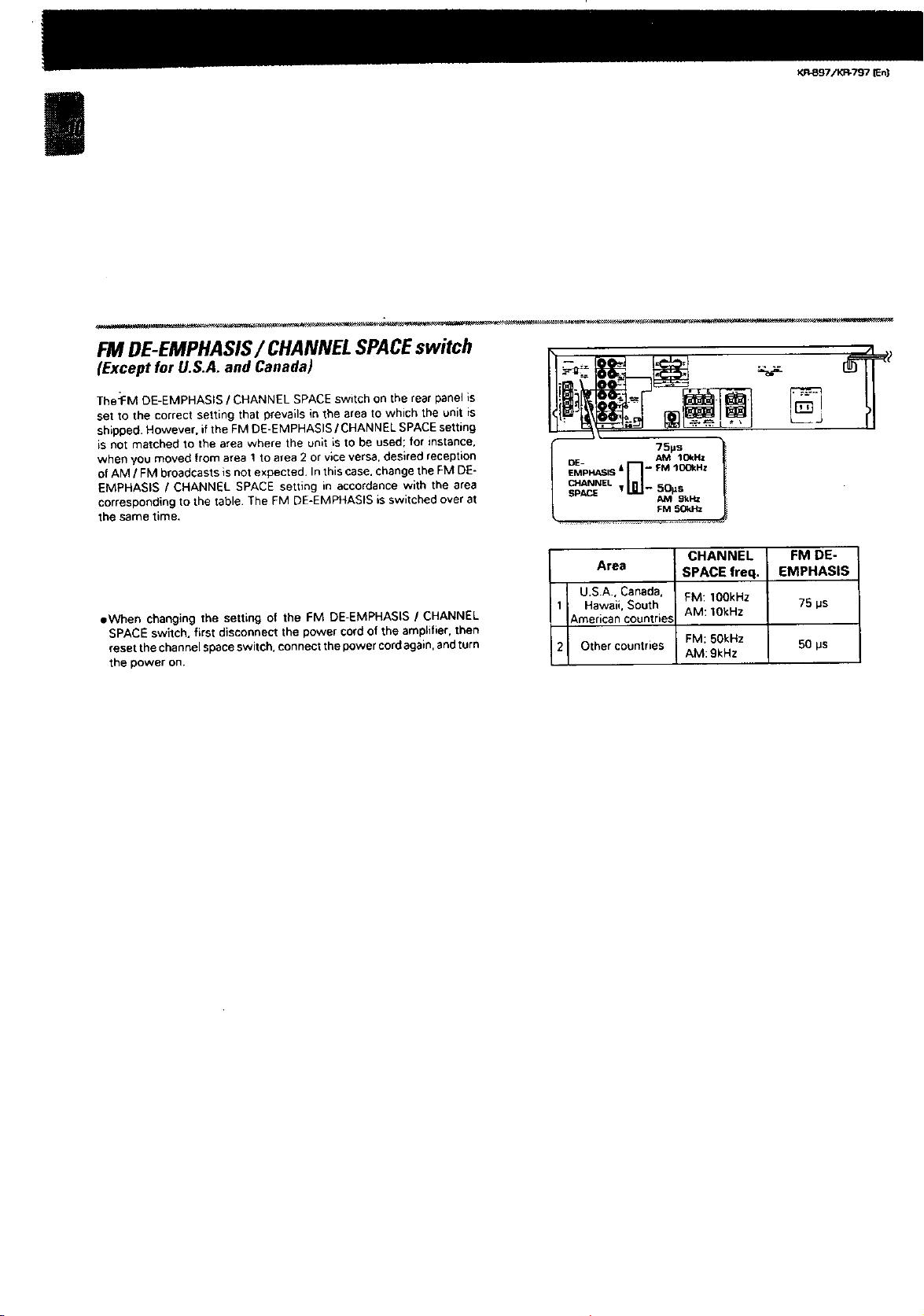
FM DE-EMPHASIS/CHANNEL SPACEswitch
(Except for U.S.A. and Canada)
The:FM DE-EMPHASIS / CHANNEL SPACE switch on the rear panel is
set to the correct setting that prevails in the area to which the unit is
shipped. However. ifthe FM DE-EMPHASIS / CHANNEL SPACEsetting
is not matched to the area where the unit is to be used; for instance.
when you moved from area I to area 2 or vice versa, desired reception
of AM / FM broadcasts is not expected. Inthis case. changethe FM DE-
EMPHASIS / CHANNEL SPACE setting in accordance with the area
corresponding to the table The FM DE-EMPHASIS is switched over at
the same time.
eWhen changing the setting of the FM DE-EMPHASIS / CHANNEL
SPACE switch, first disconnect the power cord of the amplifier, then
reset the channel spaceswitch, connect the power cordagain, and turn
the power on.
%
OE- AM 1C4_HZ
EMPHAE;IS & -- FM lOOkHz
I - 50_sCHANNEL
SPI SPACE _M gkHz l
Area SPACE freq. EMPHASIS
U.SA, Canada, FM: 1OOkHz 75 ps
1 Hawaii. South AM: 1OkHz
American countries
2 Other countries FM: 50kHz 50 ps
FM SOl_tz
CHANNEL FM DE-
AM: 9kHz
 Loading...