

Kenwood KR-897 User Manual

KENWOOD
AUDIO VIDEO SURROUND RECEIVER
KR-897
KR-797
INSTRUCTION MANUAL
KENWOOD CORPORATION
This manual contains instructions for two models. Model availability and features
(functions) may differ depending on country and sales area.
Model KR-897 is not available in except for U.S.A. and Canada.
B60-3069-00 Ce§) (K, P. Y) iMCj
98/12 11 10 98765432 1 97/12 11 10 9
■
Units are designed for operation as foHows.
U.S:A. and Canada............................................................AC120 V only
Australia.............................................................................AC 240 V only
AmSmSm
Europe and U.K.
China and Russia
*Other eottotries
...............................................................
....................................;.......................
............................
AC 110-120/220-240 Vswitehable
КЯВ97/КЯ797 [EnJ
AC 230 V only
AC 220 V only
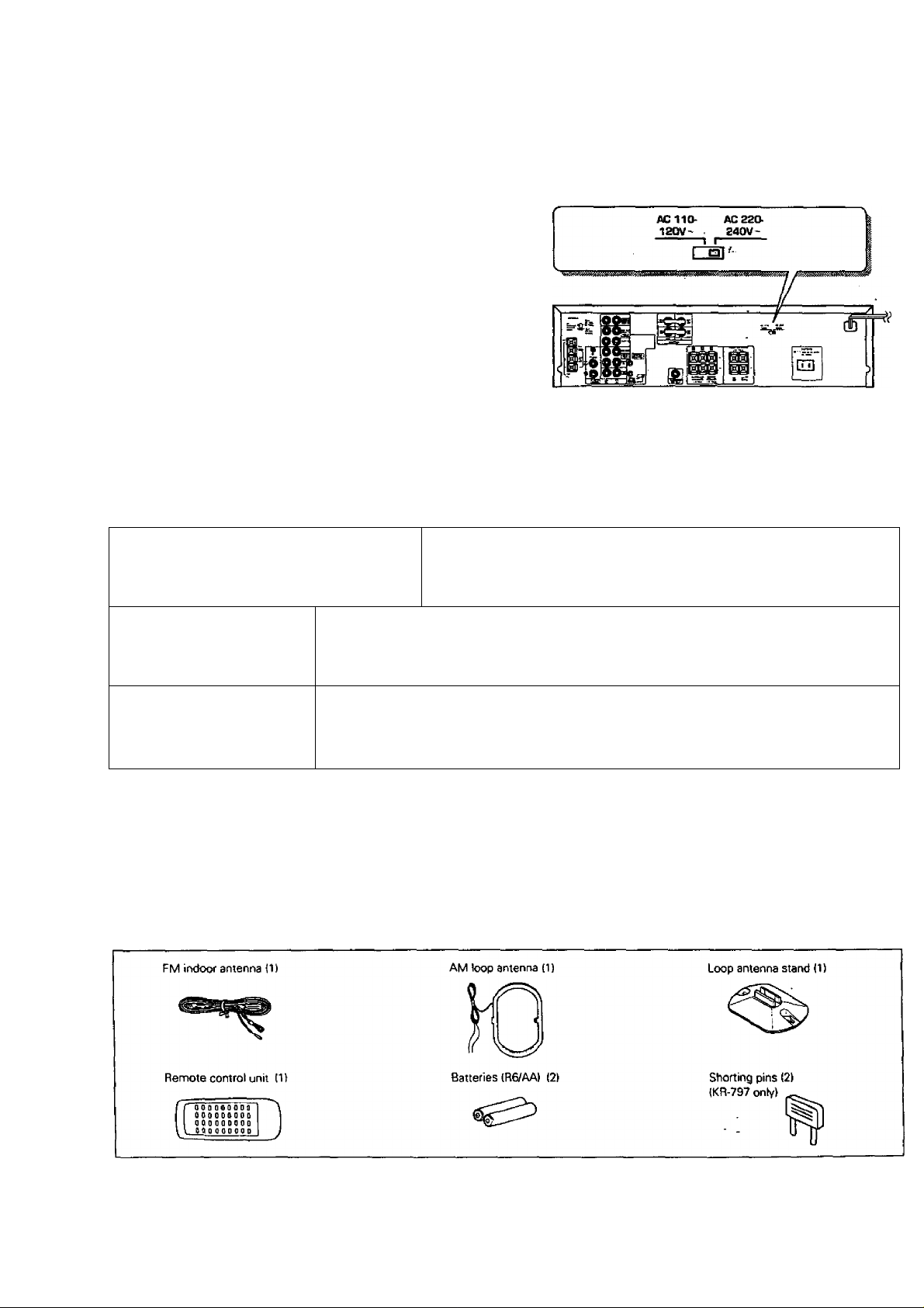
*AC voltage selection
The AC voltage selector switch oo the rear pane! is set to the voltage
that prevails In the area to which the unit is shipped. Before connectirtg
the power cord to your AC outlet, make sure that the setting position
of this switch matches your line voltage. If not. it must be set to your
voltage in accordance with the following direction.
Note:
■Our warranty does not cover damage caused by excessive line voltage
due to improper setting of the AC voltage selector switch.
Safety precautions
Caution: Read this section carefuliy to ensure safe operation.
Move switch lever to match your line voltage
with a small screwdriver or other pointed tool.
AC voltage selector switch
WARNING; TO PREVENT FIRE OR ELECTRIC SHOCK, DO NOT EXPOSE THIS
APPLIANCE TO RAIN OR MOISTURE. .
CAUTION; TO REDUCE THE RISK OF ELECTRIC SHOCK, DO NOT REMOVE COVER
(OR BACK). NO USER-SERVICEABLE PARTS INSIDE, REFER SERVICING TO QUALI
FIED SERVICE PERSONNEL.
THE LIGHTNING FLASH WITH ARROWHEAD SYMBOL, WITHIN AN EQUILATERAL TRIANGLE, IS IN
TENDED TO ALERT THE USER TO THE PRESENCE OF UNINSULATED "DANGEROUS VOLTAGE" WITHIN
THE PRODUCT'S ENCLOSURE THAT MAY BE OF SUFFICIENT MAGNITUDE TO CONSTITUTE A RISK OF
A
ELECTRIC SHOCK TO PERSONS.
THE EXCLAMATION POINT WITHIN AN EQUILATERAL TRIANGLE IS INTENDED TO ALERT THE USER TO
THE PRESENCE OF IMPORTANT OPERATING AND MAINTENANCE (SERVICING) INSTRUCTIONS IN THE
A
LITERATURE ACCOMPANYING THE APPLIANCE.
Unpackim
Unpack the unit carefully and make sure that all accessories are put aside so they will not be lost. Examine the unit for any possibility of shipping damage.
If your unit is damaged or fails to operate, notify your dealer immediately. II your unit was shipped to you directly, notify the shipping company without delay.
Only the consignee (the person or company receiving the unit) can file a claim against the carrier for shipping damage. We recommend that you retain the
original carton and packing materials for use should you transport or ship the unit in the future.
Accessories

§BSS¡MUS3MS§m
DOLBY PRO LOGICA DOLBY 3 STEREO
The suirouad system reproduces video soffware programs carrying tiie |XI[§
theaters.
The DOLBY PRO LOGIC mode controls the audio signals of the Front leff/ftigkt. Center and Rear surround channels using the built-in
directivity enhancer circuit to reproduce the feeling of sound motions very realistically.
TheDOLBY3STEREOmodecanreproducethemotionsofsoundevenwbenonlytbefrontandcenterspeakersareused.byprovidingpraper
acoustic position using the directivity enhancer circuit.
SRS 3D Stereo
The SRS ¡Sound Retrieval System) is an Innovative system simulating a 3-dimensional sound space, which features clearly improved
feelings of depth, sound field extension and acoustic image positioning as vvell as a widened listening area.
KF^ag7/KR-797 (Ení
il mark with similar acoustic effects to movie
Contente
Before applying power
Special features
System connection
Controls and indicators
Operation of remote control unit
Playing music
Sound adjustment functions
Hecordia
Broadcast receptiong
Presence play
In case of difficulty
A Specifications
... . .. .. . .. .. .. . .. .. . .. .. . .. .. . .. .. . .. .. . .. .. . .. .. . .. .. .. . .. .. . .. .. . .. .. . .. .. . .. .. . .. .. . .. .. . .. .. .. . .. .. . .. .. . .. .. . .. .. . .. .. . .. .. . .. .. .. . .. .. . .. .. . .. .. . .. .. . .. .. . .. .. . .. .. . .. . 3
.. . .. . . . . ..... . .. .. . .. . .. .. . .. .. . .. .. . .. . .. .. . .. .. . .. .. . .. . .. .. . .. .. . .. .. . .. . .. .. . .. .. . .. . .. .. . .. .. . .. .. . .. . .. .. . .. .. . .. .. . .. . .. .. . .. .. . .. . .. .. . .. .. . .. .. . .. . .. .. . .. .. . .. .. .
... . .. . .. . .. . .. . ..... . .. . .. .. . .. . .. .. . .. . .. . .. .. . .. . .. .. . .. . .. .. . .. . .. . .. .. .... . ..... . .
... . .. .. . .. .. .. . .. .. . .. .. . .. .. . .. .. . .. .. . .. ...... . .. . .. . .. . .. . .. . .. . .. .
... . .. .. . .. .. .. . .. .. . .. .. . .. .. . .. .. . .. .. . .. .. . .. .. . .. .. .. . .. .. . .. .. . .. .. . .. .. . .. .. . .. .. . .. .. . .. .. .. . .. .. . .. .. . .. .. . .. .. . .. .. . .. .. . .. .. .. . .. .. . .. .. . .. .. . .. .. . .. .. . .. .. . ..
... . .. .. . .. .. .. . .. .. . .. .. . .. .. . .. .. . .. .. . .. .. . .. .. . .. .. .. . .. .. . .. .. . .. .. . .. .. . .. .. . .. .. . .. .. . .. .. .. . .. .. . .. .. . .. .. . .. .. . .. .. . .. .. . .. .. .. . .. .. . .. .. . .. .. . .. .. . .. .. . .. .. . .. .. . .. .. .
.
... . .. .. . .. .. .. . .. .. . .. .. . .. .. . .. .. . .. .. . .. .. . .. .. . .. .. .. . .. .. . .. .. . .. .. . .. .. . .. .. . .. .. . .. .. . .. .. .. . .. .. . .. .. . .. .. . .. .. . .. .. . .. .. . .. .. .. . .. .. . .. .. . .. .. . .. .. . .. .. . .
... . .. .. . .. .. .. . .. .. . .. .. . .. .. . .. .. . .. .. . .. .. . .. .. . .. .. .. . .. .. . .. .. . .. .. . .. .. . .. .. . .. .. . .. .. . .. .. .. . .. .. . .. .. . .. .. . .. .. . .. .. . .. .. . .. .. .. . .. .. . .. .. . .. .. . .. .. . .. .. . .. .. . .. .. . .. .. .. . ..
Caution: Read the pages marked A carefuily to
ensure safe operation.
... . .. . .. . .. . .. . .. . .. . .. . ...... . .. . .. .. . .. . .. .. . .. . .. . .. .. . .. . .. .. . .. . .. .. . .. . .. . .. .. . .. . .. .. ..... . .. .. . .. . .. .. . .. .. . .. .. . .. . .. .. . .. .. . .. .. . .. . .. .. . ..... . . . . ..... .. . .. . .. . .
A Before applying power
A Safety precautions
Connections of Audio and Video components fKR-897)
' Connections of Audio and Video components (KR-797)
About the system control connections
■
Connection of speakers (KR-897)
Connection of speakers IKR-797)
Connection of antenna
■
FM DE-EMPHASIS/CHANNEL SPACE switch
... . .. .. . .. .. .. . .. .. . .. .. . .. .. . .. .. . .. .. . .. .. . .. .. . .. .. .. . .. .. . .. .. . .. .. . .. .. . .. .. . .. .. . .. .. . .. .. .. . .. .. . .. .. . .. .. . .. .. . .. .. . .. .. . .. .. .. . .. .. . .. .. . .. .. . .. .. . .. .. . .. .. .
... . .. .. . .. .. .. . .. .. . .. .. . .. .. . .. .. . .. .. . .. .. . .. .. . .. .. .. . .. .. . .. .. . .. .. . .. .. . .. .. . .. .. . .. .. . .. .. .. . .. .. .... . ..
... . .. .. . .. .. .. . .. .. . .. .. . .. .. . .. .. . .. .. . .. .. . .. .. . .. .. .. . .. .. . .. .. . .. .. . .. .. . .. .. . .. .. . .. .. . .. .. .. . .. .. . .. .. . .. .. . .. .. . .. .. . .. .. . .. .. .. . .. .. . .. .. . .. .. . .. .. . /5
Receiving broadcast stations
Receiving radio stations by specifying its frequency
Storing radio stations in memory (Station preset)
Receiving a preset station
Receiving all preset stations in order (P. CALL)
Adjustments for surround play
Surround play
SRS 3D Stereo (Sound Retrieval System)
... . .. .. . .. .. .. . .. .. . .. .. . .. .. . .. .. . .. .. . .. .. . .. .. . .. .. .. . .. .. . .. .. . .. .. . .. .. . .. .. . .. .. . .. .. . .. .. .. . .. .. . .. .. . .. .. . .. .. . .. .. .
... . .. .. . .. .. .. . .. .. . .. .. . .. .. . .. .. . .. .. . .. .. . .. .. . .. .. .. . .. .. . .. .. . .. .. . .. .. . .. .. . .. .. . .. .. . .. .. .. . .. .. . .. .. . .. .. . .. .. . .. .. . .. ..
... . .. .. . .. .. .. . .. .. . .. .. . .. .. . .. .. . .. .. . .. .. . .. .. . .. .. .. . .. .. . .. .. . .. .. . .. ..
... . .. . .. .. . .. . .. .. . .. . .. . .. .. . .. . .. .. . .. . .. .. . .. . .. . .. .. . .. . .. .. . .. . .. .. . .. .
... . .. .. . .. .. .. . .. .. . .. .. . .. .. . .. .. . .. .. . .. .. . .. .. . .. .. .. . .. .. . .. .. . .. .. . .. .. . .. .. . .. .. . .. .. . .. .. .. .. 6
... . .. .. . .. .. .. . .. .. . .. .. . .. .. . .. .. . .. .. . .. .. . .. .. . .. .. .. . .. .. . .. .. . .. .. . .. .. . .. .. . .. .. . .. .. . .. .. .. . .. .. . .. .. . ..7
... . .. .. . .. .. .. . .. .. . .. .. . .. .. . .. .. . .. .. . .. .. . .. .. . .. .. .. . .. .. . .. .. . .. .. . .. .. . .. .. . .. .. . .. .. . .. .. .. . .. .. . ..
... . .. .. . .. .. .. . .. .. . .. .. . .. .:.. .. . .. .. . .. .. .. . .. .. . .. .. . .. .. . .. .. . .. .. . .. .. . .. .. .. . .. .. . .. .. . .. .. . .. .. . .. .. . .. .. . .. .. . .
... . .. .. . .. .. .. . .. .. . .. .. . .. .. . .. .. . .. .. . .. .. . .. .. . .. .. .. . .. .. . ..ZZ.ZZZ.... ;0
... . .. .. . .. .. .. . .. .. . .. .. . .. .. . .. .. . .. .. . .. .. . ..
... . .. ..... . .. . .. .. . .. . .. .. . .. . .. . ..... .. . .. . .. . .. . .. . .. .... . . .. . . .... .. . .. . .. . .. . .. . .. . .. . .
... . .. .. . .. . .. .. . .. .. . .. .. . .. . .. .. . .. .. . .. .. . .. . .. .. . .. .. . .. .. . .. . .. .. . .. .. . .. . .. .. . .. .. . .. .. . .. . .. .. . .. .. . .. .. . .. . .. .. .
... . .. .. . .. .. .. . .. .. . .. .. . .. .. . .. .. . .. .. . .. .. . .. .. . .. .. .. . .. .. . .. .. . .. .. . .. .. . .. .. . .. .. . .. .. . .. .. .. . .. .. . .. ..
... . .. .. . .. .. .. . .. .. . .. .. . .. .. . .. .. . .. .. . .. .. . .. .. . .. .. .. . .. .. . .. .. . .. .. . .. .. . ..
... . .. .. . .. .. .. . .. .. . .. .. . .. .. . .. .. . .. .. . .. .. . .. .. . .. .. .. . .. .. . .. .. . .. .. . .. .. . .. .. . .
... . .. .. . .. .. .. . .. .. . .. .. . .. .. . .. .. . .. .. . .. .. . .. .. . .. .. .. . .. .. . .. .. . .. .. . .. .. . .. .. . .. .. . .. .. . .. .. .. . .. .. . .. .. . .. .7;
... . .. . .. . .. . .. . .. .. . .. . .. . .. . .. .. . .. . .. . .. . .. . .... .. . .. . .. .. . .. . .. . .. . .. .. . .. . .. . .. .
... . .. .. . .. .. .. . .. .. . .. .. . .. .. . .. .. . .. .. . .. .. . .. .. . .. .. .. . .. .. . .. .. . .. .. . .. .. . .. .. . .. .. . .. .. . .. .. .. . .. .. . .. .. .
... . .. .. . .. .. .. . .. .. . .. .. . .. .. . .. .. . .. .. . .. .. . .. .. . .. .. .. . .. .. . .. .. . .. .. . .. .. . .. .. .... .. . .. . .. . . .. . .. . ..... . .. . .. . .. . .. . .. . .. . .. . ..
... . .. .. . .. .. .. . .. .. . .. .. . .. .. . .. .. . .. .. . .. .. . .. .. . .. .. .. . .. .. . .. .. . .. .. . .. .. . .. .. . .. .. . .. .. .
2
2
2
4
4
5
g
g
jj
12
jg
..
jg
ig
20
21
21
^23
24
26
27
28
gg
KM97/KH-797 [EnJ
Connections of Audio and Video components (KR-897)
..............
Make connection as shown below.
When connecting the related system components, refer
also to the instruction manuals of the related compo
nents.
A Do not plug in the power lead until all connections are
completed.
Cassette deck 1, MD recorder
Malfunction of microcomputer
If operation is not possible or erroneous tfisplay appears even
thoughalt connections have been made property, reset the micro
computer referring to *ln case of difficulty'. “CflC
^SSSS^ÊMSM^Ê2ÆÉJÙâËË£3S!ËSS!S!^MBJÿ!L
Make connection as shown below.
When connecting the related system components, refer
also to the instruction manuals of the related compo
nents.
A Do not plug ill the power lead until all connections are
completed.
Video deck 1, cassette deck 1
OUT
Audio
IN
Video deck 2 or DVD/LD player
Audio OUT
*2 Cassette
1 t
or MD recorder
CTT-T-T’^ ssoo C M [ 1 1 1
Î
------------------------
Q \
0 o o l . . loooo oc
—^
Malfunction of microcomputer
H operation is not possible or erroneous display appears even
though all connections have been made properly,resetthe micro
computer referring to “In case of difficulty’. —[3£]
»
--------------------
1 1,
i
№897/KR-797 (En)
I
cassette deck
KX-W597/KX-W797*i
System
control cord
Graphic
equalizer
KE-597
II Lili sso 0 0 lililí
System control cwd
To wall
AC outlet
^ The system control cord should be connected when a
KENWOOD audio component system is connected.
Do not connect system control cord to the cassette
deck connected to the TAPE 2 MONITOR jacks.
*3 The KX-W797 and KM-897 are not marketed in other
areas than the USA and Canada.
T urntable
Multipul CD player
DP-R797
Caution regarding piacement (Except for U.S.A. and Canada)
To maintain proper ventiiation, be sure to leave a space aroundthe
unit (from the largest outer dimensions inciuding projections)
equal to, or greater than, shown below.
Left and right panels : 10 cm
Rear panel : 10 cm
Top panel : 50 cm
About the system control connections
KR897/KR797 (En)
I
Connecting system control cords efter connecting a KENWOOD audio component system lets you take advantage of convenient
system control operations.
There are two KENWOOD system control modes. Make connections according to the groups of terminal symbols shown below.
CXSS Mode: lets you combine DCO, DCS, and CXS81 terminals
[SL1EI Mode: for [^lE) terminals only
This unit is compatible with both EXS8] and [SU6] modes. It comes from the factory set to the [SL16] mode. To switch tothe{XS81
mode, follow the instructions in ‘SWITCHING BETWEEN [XS8] AND [SL16]‘ below. '
EXAMPLE: IXS8] mode connections
The underlined portion represents the setting of the system
control mode.
Turntable
JSL161 [XS8]
(SLl 6]
[SL16] IXS] [XS8] [XR]
ISL16] (XS) [XS81
e Some CD players and cassette decks are not compatible with the ISL161 system control mode. Be sure fo úse the (XS81 system control mode when
making system connections with equipment that is not ISL161 compatible.
eSome MD players are not system control compatible. You cannot make system control connections to this kind of equipment.
Receiver
MD Recorder
LD Player
Cassette Deck
Multiple
GD Player
1
J
System
control
cord
EXAMPLE: (SL16I mode connections
The underlined portion represents the setting of the system
control mode.
Turntable
[SL161 [XS81
[SL16]
(SL16) [XS] IXS8Í [XRJ
[SL16] [XS] [XS8]
Receiver
MD Recorder
LD Rayer
Cassette Deck
Multiple
CD Player
"[ I
J System
-y control
cord
J
J
1. (SLl 6| equipment cannot be combined with (XRl, (XSI. and IXS8I equipment for system operations. If your
equipment consists of this kind of combination, please do not connect any system control cords. Even
without system control cords, normal operations can be carried out without affecting performance.
2. Do not connect system control cords to any components otherthan those specified by KENWOOD. It may
cause a mslfunction and damage your equipment.
3. Be sure the system controi plugs are inserted all the way in to the system control termir>als,
ABOUT THE SYSTEM CONTROL OPERATIONS
Remote Control (possible whert the system control mode
matches)
Lets you operate source components with the system remote
supplied with this unit.
Automatic Operation (Except [XR] equipment)
When you start playback from a source component the input
selector on this unit switches to that component automatically.
(Except TAPE 2)
Synchronized Recording (Except [XR] equipment)
Lets you synchronize recording with the start of playback when
recording from CD or MD.
SWITCHING BETWEENp(S8]AND [SL16]
The system control mode can be switched over easily with the
following operation.
O Unplug the AC power cord from the wall outlet.
® Set the SYSTEM CONTROL switch on the rear panel to the desired
position.
SYSTEM
coPimoL
(osa)-^ I
a
GLIB—'
eThis operation does not aifect the items stored in memory.
1. Connect all cords firmly, If connections are loose, there could be toss of sound or noise produced.
2. When plugging and unplugging connection cords, be sure to first remove the power cord from the AC outlet. Plugging / unplugging connection
—' cords without removal of the power cord can cause malfunctions or damage to the unit.
3. If the system control cords or audio cords are not connected properly, the remote control or automatic operation between system components
will not work properly.

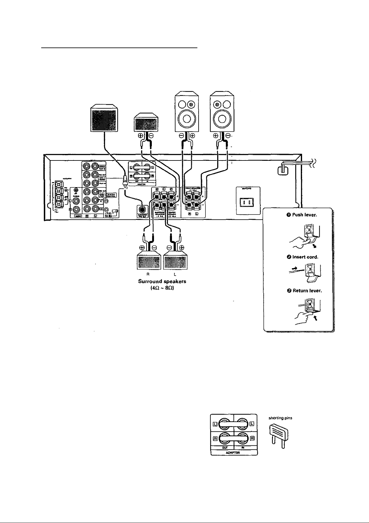
Connection of speakers (KR-897)
KM97/KH-797 (En)
Center speaker Powerd
(8Q ~ 16Q) sub-woofer
- -
1 KMi g) [Q
lavcnM 1
iBHim. 1
§>
©
ELB—'
Speaker system A
(Sn - 16QI
R L
Q®
Connect the speakers for use in
surround play to speaker sys
tem A.
Speaker system B does not out
put sound during surround play.
11
-E+l
+ B *
I • - s
Speaker system B
(8£i ~ 16iiJ
CMTEp/ UNEM 1
MAiyiH
Surround speakers
(4n ~ SO)
*1 For the operation of the
power amplifier (KM-897J,
refer to the instruction
manual of the power am
plifier (KM-897).
The speakers connected to the KR-897 and
KM-897 reproduce sound as described below.
When surround play is used:
KR-897 SPEAKERS key; ON
KM-897 Key: D SURROUND
Stereo play using the KR-897: Speakers used for reproduction
KR-897 SPEAKERS key; ON : Speaker system A/Sub-woofer
KM-897 POWER key; 11 OFF ;
Stereo play using the KM-897: Speakers used for reproduction
KR-897 SPEAKERS key: OFF ;
KM-897 Key; a. STEREO : Speaker system B
HEADPHONES play using only: Speakers used for reproduction
KR-897 SPEAKERS key: OFF ;
KM-897 POWER key: Q OFF ;
I For the installation and adjustment of speakers for surround play
Speakers used for reproduction
: Speaker system A/Sub-woofer
; Center speaker/Surround speakers
----------------------------------------------
----------------------------------------------
----------------------------------------------
----------------------------------------------
»Never short-circuit the + and - speaker cords. For the symptom and remedy when a speaker cord is shorted. .
»If the left and right speakers are connected inversely or if the speaker cords are connected with reversed polarity, the sound becomes unnatural with
ambiguous acoustic image positioning. Be sure to connect the speakers and speaker cords correctly.
• Connect a sub woofer if you want to enhance the bass sound. The connected sub-woofer should be a power sub-woofer with a built-in amp.
■
mt
KFW97/KB-797 {En)
Connection of speakers (KR-797)
Powerd Center speaker
sub-woofer (8Q ~ 16Q)
Speaker systern
(Sn ~ 16QI
R L
• Never short-circuit the + and - speaker cords. For the symptom and remedy when a speaker cord is shorted:
• If the left and right speakers are connected inversely or if the speaker cords are connected with reversed polarity, the sound becomes unnatural with
ambiguous acoustic irhage positioning. Be sure to connect the speakers and speaker cords correctly,
• Connect a sub woofer if you want to enhance the bass sound. The connected sub-woofer should be a power sub-woofer with a built-in amp.
ADAPTOR jacks (KR-797)
When an adaptor-type component such as a graphic equalizer is
connected, unplug the shorting pins from the ADAPTOR jacks and
connect the component to these jacks,
•When the ADAPTOR jacks are not used, be sure to plug the shorting
pins into jacks. Otherwise, the sound will not be produced,
•When the ADAPTOR jacks are used, retain the shorting pins and be
careful not to lose them.
• Never plug a shorting pin into other jacks than ADAPTOR jacks.
Otherwise, the unit may be damaged.
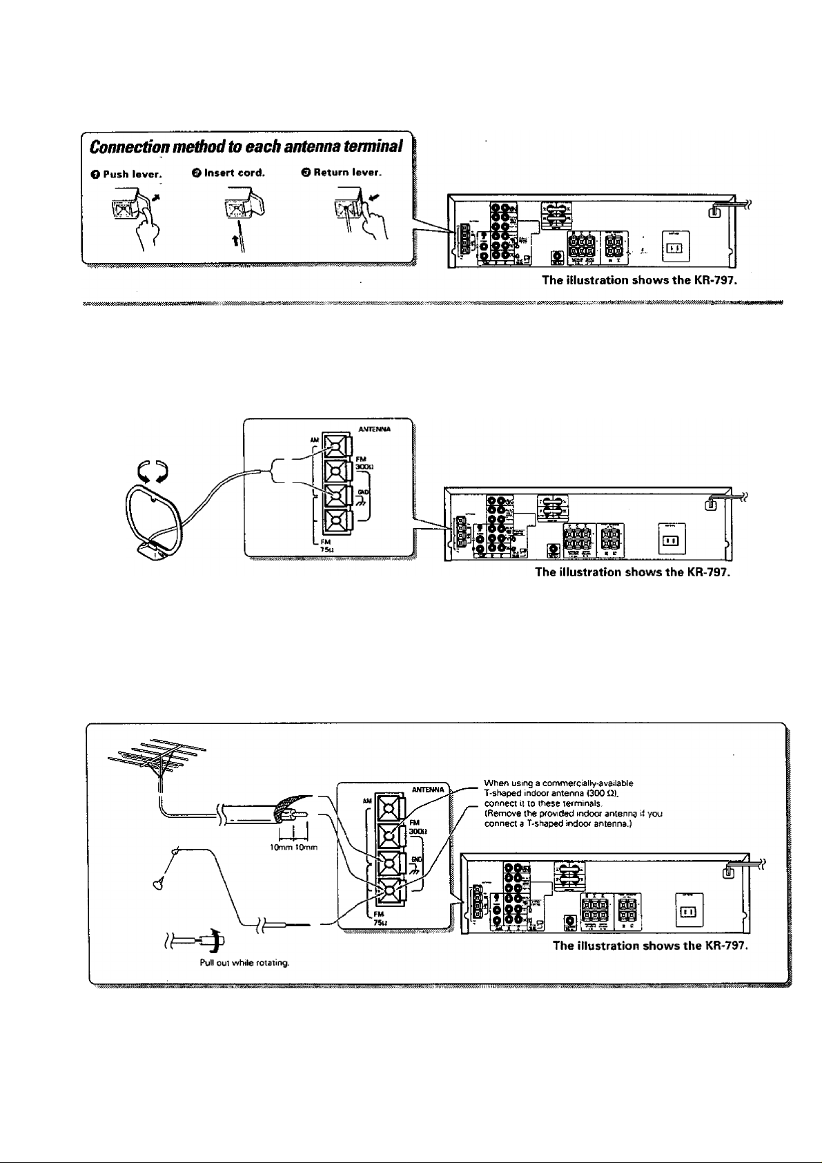
Connection of antenna
AM loop antenna connection
The supplied anierma is for indoor use. Place it as far as possible from ihe
main system. TV set. speaker cords and power cord, and set it to a
direction which provides the best reception.
KRe97/KB-797 I6l)
I
FM indoor antenna connection
The accessory antenna is for temporary indoor use only. For stable signal
reception we recommend using an outdoor antenna. Remove the indoor
antenna if you connect one outdoors.
FM outdoor antenna connection
Lead the 75 Q coaxial cable connected to the FM outdoor antenna into
the room and connect it to the FM 75 ii terminal.
I
KRS97/KR-797 (En)
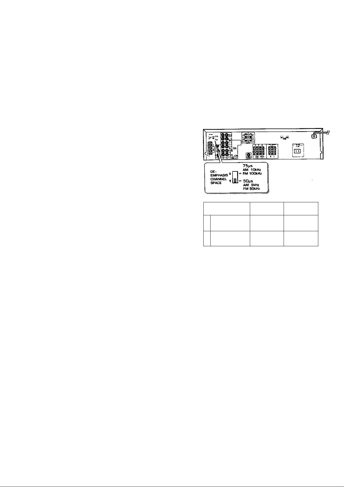
FM DE-EMPHASiS/CHANNEL SPACE switch
(Except for U.S.A. and Canada)
ThefM DE-EMPHASIS / CHANNEL SPACE switch on the rear panel is
set to the correct setting that prevails in the area to which the unit is
shipped. However, if the FM DE-EMPHASIS/CHANNEL SPACE setting
is not matched to the area where the unit is to be used; for instance,
when you moved from area 1 to area 2 or vice versa, desired reception
of AM / FM broadcasts is not expected. In this case, change the FM DE
EMPHASIS / CHANNEL SPACE setting in accordance with the area
corresponding to the table. The FM DE-EMPHASIS is switched over at
the same time.
•When changing the setting of the FM DE-EMPHASIS / CHANNEL
SPACE switch, first disconnect the power cord of the amplifier, then
reset the channel space switch, connect the power cord again, and turn
the power on.
Area
U.S.A., Canada,
1
Hawaii. South
American countries
Other countries
2
CHANNEL
SPACE freq.
FM: 100kHz
AM: 10kHz
FM: 50kHz
AM: 9kHz
FM DE
EMPHASIS
75 ps
50 ps
 Loading...