

Kenwood KR-6340 Owners manual
brought to you by www.stephsrecordsale.com
Because Kenwood Electronics, Inc., takes great pride in the long tradition of quality
brought to you by www.stephsrecordsale.com
components the name Kenwood represents, your purchase of a Kenwood two-four receiver
places you in a distinguished family of connoisseurs of superb high-fidelity sound reproduc-
tion.
The purpose of this manual is to acquaint you with the operating features of your new
receiver. You will notice that in every detail of planning, engineering, styling, operating
convenience, and adaptability, we have sought to anticipate your needs and desires.
We suggest that you read this manual carefully. Knowing how to set up your receiver
to best advantage will enhance your listening pleasure right from the start. You will also
become aware of the ease with which you can adjust your receiver to meet your special
requirements.
Turn the pages and become acquainted with the exciting features of your new receiver,
features that will remain new for endless hours of listening pleasure.
KR-6340 FEATURES 3
INTERCONNECTING DIAGRAM 4
CONNECTING YOUR KR-6340 5
CONTROLS AND THEIR FUNCTIONS 8
OPERATING INSTRUCTIONS 10
RM/SQ/CD-4 INTRODUCTION 12
MAINTENANCE 13
TROUBLE SHOOTING 14
KR-6340 SPECIFICATIONS 16
KR.6340 FEATURES
brought to you by www.stephsrecordsale.com
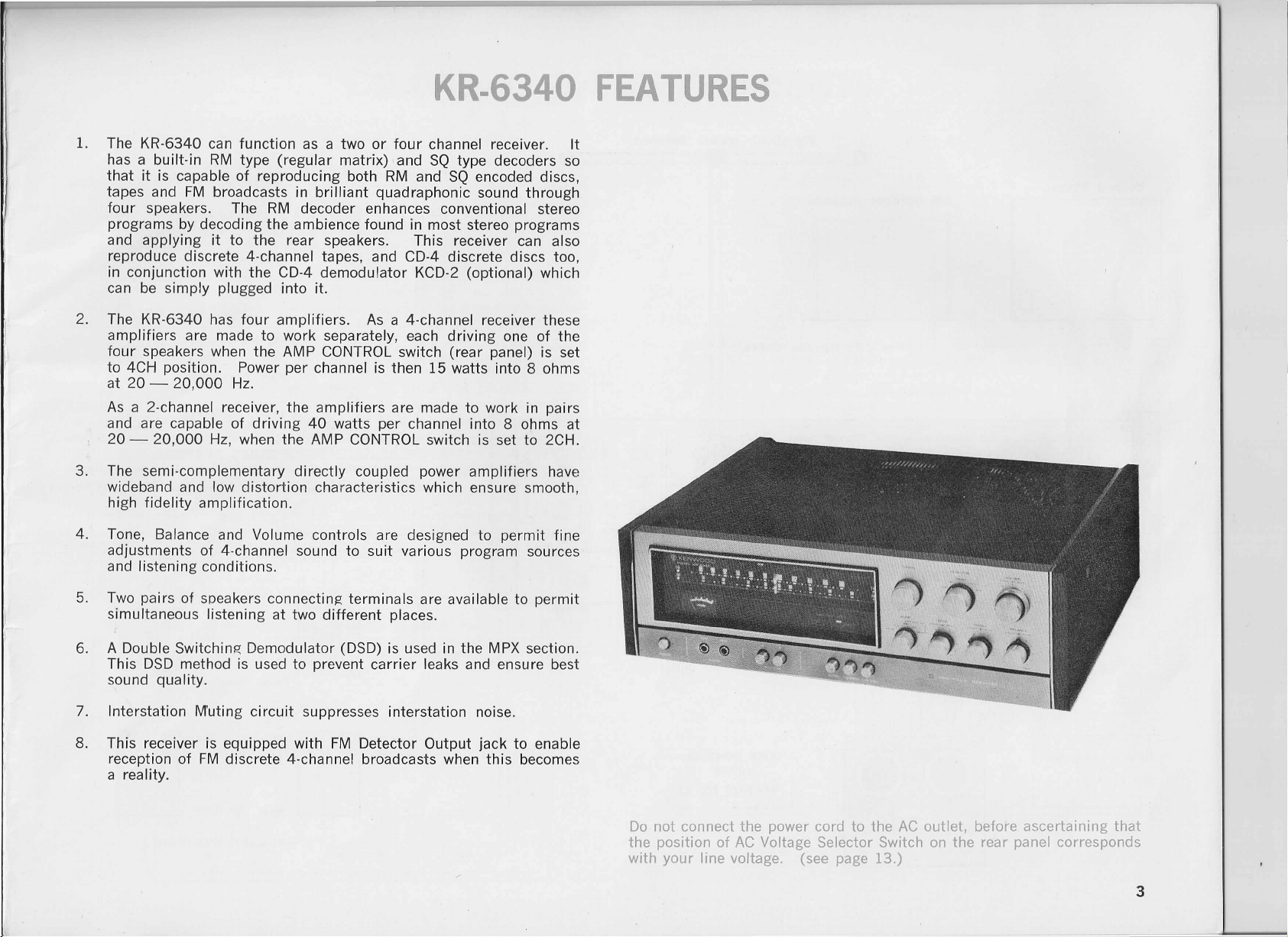
1. The KR-6340 can function as a two or four channel receiver. It
has a built-in RM type (regular matrix), and SQ type decoders so
that it is capable of reproducing both RM and SQ encoded discs,
tapes and FM broadcasts in brilliant quadraphonic sound through
four speakers. The RM decoder enhances conventional stereo
programs by decoding the ambience found in most stereo programs
and applying it to the rear speakers. This receiver can also
reproduce discrete 4-channel tapes, and CD-4 discrete discs too,
in conjunction with the CD-4 demodulator KCD-2 (optional) which
can be simply plugged into it.
2. The KR-6340 has four amplifiers. As a 4-channel receiver these
amplifiers are made to work separately, each driving one of the
four speakers when the AMP CONTROL switch (rear panel) is set
to 4CH position. Power per channel is then 15 watts into 8 ohms
at 20 - 20,000 Hz.
As a 2-channel receiver, the amplifiers are made to work in pairs
and are capable of driving 40 watts per channel into 8 ohms at
20 - 20,000 Hz, when the AMP CONTROL switch is set to 2CH.
3. The semi·complementary directly coupled power amplifiers have
wideband and low distortion characteristics which ensure smooth,
high fidelity amplification.
4. Tone, Balance and Volume controls are designed to permit fine
adjustments of 4-channel sound to suit various program sources
and listening conditions.
5. Two pairs of speakers connecting terminals are available to permit
simultaneous listening at two different places.
6. A Double Switching Demodulator (DSD) is used in the MPX section.
This DSD method is used to prevent carrier leaks and ensure best
sound quality.
8. This receiver is equipped with FM Detector Output jack to enable
reception of FM discrete 4-channel broadcasts when this becomes
a reality.
Do not connect the power cord to the AC outlet, before ascertaining that
the position of AC Voltage Selector Switch on the rear panel corresponds
with your line voltage. (see page 13.)
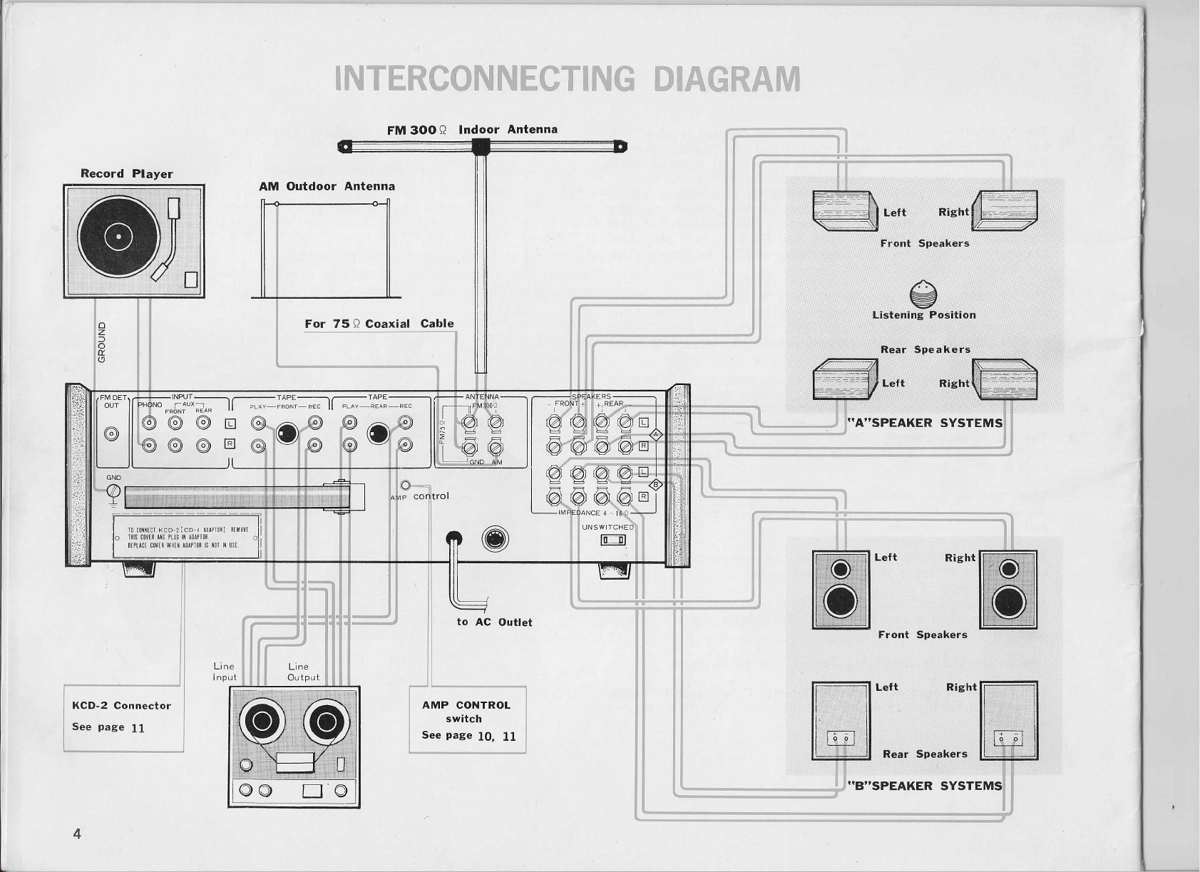
INTERCONNECTING DIAGRAM
brought to you by www.stephsrecordsale.com
~
Listening Position
AMP CONTROL
switch
See page 10, 11
1
i;,~,1
Rear Speakers ~
"."SPEAKER SYSTEMS!
CONNECTING YOUR KR·6340
brought to you by www.stephsrecordsale.com
Connecting The "A" Speakers
Place the four speakers in your listening room as shown in the
interconnecting diagram. Your listening position should be at the
center of the four speakers, and facing the front speakers.
Speaker connections are made to the "A" SPEAKERS terminals as
follows. The left-front speaker's (-) side should be connected to the
L-FRONT (-) amp terminal. Its
L-FRONT
(+)
terminal. The right-front, left-rear and right-rear speakers
should be connected, respectively, to the R-FRONT, L-REAR and
R-REAR terminals in the same manner,
Any two-conductor wire such as an AC cord can be used as a
speaker cord, but a "zip-cord" which is color coded is most convenient
for making proper
(+)
to
recommended that spade lugs are soldered to the tips of the speaker
cord leads. When spade lugs are not used, be sure to twist together the
strands of each individual lead to eliminate any possibility of short-
circuits forming in the speaker connecting network.
If
you intend to use only the "A" speakers for conventional 2-chan-
nel stereo, they should be positioned at the front. Be sure make proper
(+)
to
(+)
and (-) to (-) connections.
(+)
side should be connected to the
(+)
to
(+)
and (-) to (-).
(+)
and (-) to (-) connections. It is
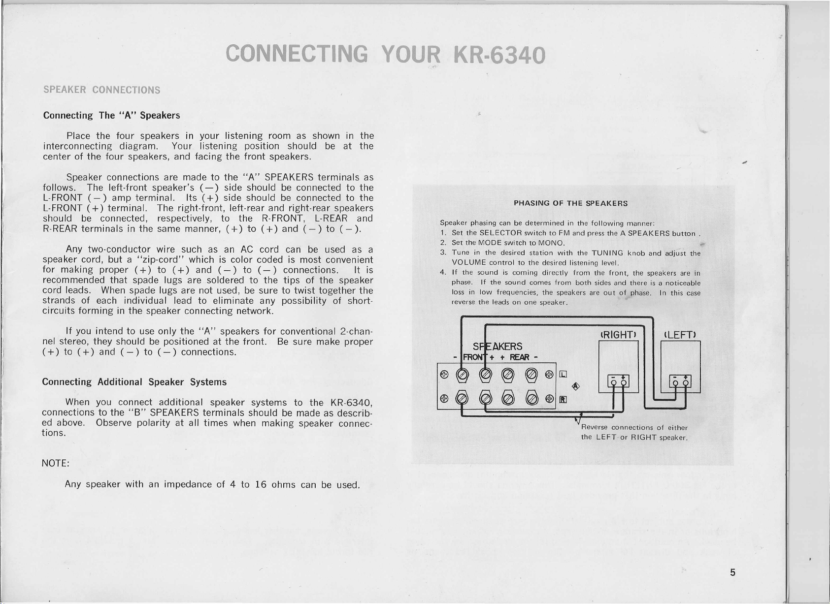
Speaker phasing can be determined in the following manner:
1. Set the SELECTOR switch to FM and press the A SPEAKERS button.
2. Set the MODE switch to MONO.
3. Tune in the desired station with the TUN ING knob and adjust the
VOLUME control to the desired listening level.
4. If the sound is coming directly from the front, the speakers are in
phase. If the sound comes from both sides and there is a noticeable
loss in low frequencies, the speakers are out of phase. In this case
reverse the leads on one speaker.
Connecting Additional Speaker Systems
When you connect additional speaker systems to the KR-6340,
connections to the "B" SPEAKERS terminals should be made as describ-
ed above. Observe polarity at all times when making speaker connec-
tions.
Reverse connections of either
the LEFT or RIGHT speaker.
CONNECTING YOUR KR·6340
brought to you by www.stephsrecordsale.com
Since FM broadcast signals travel along a straight, direct-line path,
they 'become rather weak behind hills and buildings even in the vicinity
of a broadcasting station. FM signals also become weak in areas distant
from a station even though there may not be any obstruction to the direct
stalled in the most effective manner for best possible FM reception.
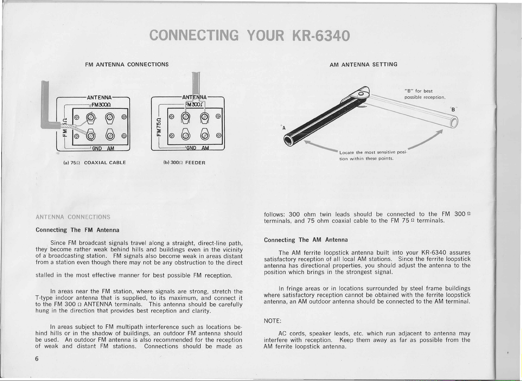
In areas near the FM station, where signals are strong, stretch the
T·type indoor antenna that is supplied, to its maximum, and connect it
to the FM 300 n ANTENNA terminals. This antenna should be carefully
hung in the direction that provides best reception and clarity.
~ Locate the most sensitive posi-
tion within these points.
follows: 300 ohm twin leads should be connected to the FM 300 n
terminals, and 75 ohm coaxial cable to the FM 75 n terminals.
Connecting The AM Antenna
The AM ferrite loopstick antenna built into your KR-6340 assures
satisfactory reception of all local AM stations. Since the ferrite loopstick
antenna has directional properties, you should adjust the antenna to the
position which brings in the strongest signal.
In fringe areas or in locations surrounded by steel frame buildings
where satisfactory reception cannot be obtained with the ferrite loopstick
antenna, an AM outdoor antenna should be connected to the AM terminal.
/
In areas subject to FM multipath interference such as locations be·
hind hills or in the shadow of buildings, an outdoor FM antenna should
be used. An outdoor FM antenna is also recommended for the reception
of weak and distant FM stations. Connections should be made as
AC cords, speaker leads, etc. which run adjacent to antenna may
interfere with reception. Keep them away as far as possible from the
AM ferrite loopstick antenna.
CONNECTING YOUR KR·6340
brought to you by www.stephsrecordsale.com
The two shielded audio cables from your stereo record player are
normally terminated with phono plugs. Connect the left channel of the
record player to the "L" PHONO input jack, and the right channel to the
"R" PHONO input jack. If the record player has a grounding wire, con-
nect it to this receiver's GND terminal to avoid hum.
Connecting Four-Channel Tape Recorder
Recording and playback of discrete 4-channel tapes can be made
with this receiver by connecting shielded audio cables with phono plugs
from a four·channel tape deck to the TAPE jacks of this receiver.
A 4-channel deck can be connected as follows for recording;
front-left channel input of the deck connects to the FRONT-L REC jack
of the KR-6340. Similarly, make the front-right, rear-left and rear-right
connections between the corresponding inputs of the deck to the
respective REC jack of the receiver.
A 4-channel tape recorder can be connected as follows for playback;
front-left channel output of the tape recorder connects fo the FRONT-L
PLAY jack of the KR-6340. Similarly, make the front·right, rear-left and
rear-right connections between the corresponding outputs of the deck
to the respective PLAY jacks of the receiver.
When a DIN cord is used to connect the tape recorder, the PLAY
and REC jacks should not be used. For highest fidelity recording and
playback it is recommended that the tape recorder be connected to the
PLAY and REC jacks instead of the DIN connector.
These inputs are suitable for connecting high level discrete 4-chan-
nel sources such as another 4-channel tape recorder, or a CD-4
demodulator other than the plug-in type CD-4 demodulator that is
available as optional equipment with the KR-6340.
Use the FRONT AUX jacks when connecting 2-channel high level
sources such as a tuner or another tape recorder.
The FM detector circuit output is made available here so that this
receiver will be ready for 4-channel broadcasting developments in the
future. When FM discrete 4-channel broadcasting becomes a reality,
a simple demodulator connected here will enable you to fully enjoy this
coming development.
The AC outlet on the rear panel of the receiver may be used to
supply power to other components such as a record player, tape recorder,
etc.
If conventional 2-channel stereo tape recorders are used for both
recording and playback, connections should be made to the TAPE
FRONT jacks. The recording inputs of the tape recorder connect to the
FRONT REC jacks of the KR-6340. Use shielded audio cables with
phono plugs. The playback outputs of the tape recorder connect to the
FRONT PLAY jacks of the KR-6340.
If your tape recorder is equipped with a DIN type 5-pin connector.
connect it to the DIN connector with a DIN connecting cord. A DIN
connector enables recording and playback with this single cord.
UNSWITCHED outlet - This outlet is available at all times. (The
maximum capacity is 200 watts.)
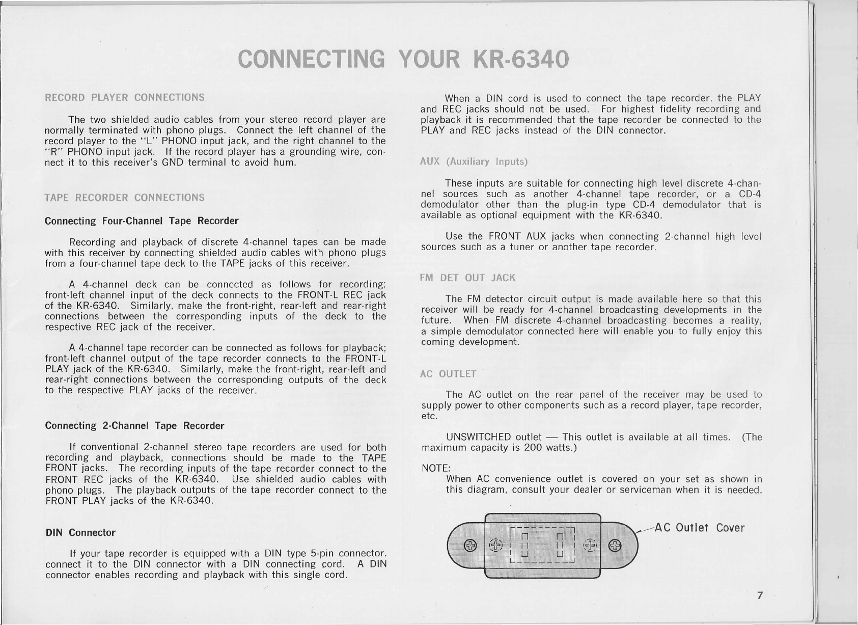
NOTE:
When AC convenience outlet is covered on your set as shown in
this diagram, consult your dealer or serviceman when it is needed.
 Loading...