

Page 1
DVD NAVIGATION SYSTEM
KNA-DV3100
KNA-DV3200
SERVICE MANUAL
The DVD mechanism infomation is not in this sarvice manual.
Please, refer to sarvice manual X92-4740-00 (B53-0052-00).
KNA-DV3100
© 2003-4 PRINTED IN JAPAN
B53-0050-00 (N) 3100
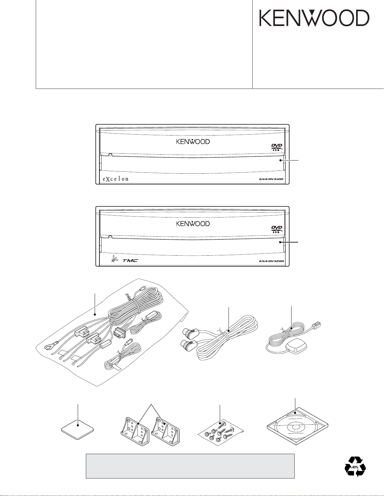
Panel assy
(A64-3105-03)
KNA-DV3200
DC cord assy
(E30-4964-05)
Mounting hardware
(J21-9867-04)
Bracket
(J19-5246-04)
Connecting cord assy
(E30-6199-05)
Screw set
(N99-1713-05)
Panel assy
(A64-3106-03)
Electric circuit module (GPS ANT)
(W02-3261-05)
DVD
(W01-1618-05) : KNA-DV3100
(W01-1619-05) : KNA-DV3200
CAUTION (Repair of NAVI board )
You can not repair IC521 (GPS Receiver) and IC701 (CORE1).
If you can repair those parts please change to NAVI board assy(W02-3395-15).
Page 2
2
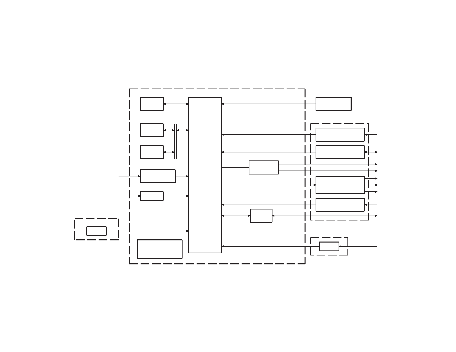
SDRAM
64MB
FLASH
2MB
SRAM
512kB
VEHICLE
GPS RF
SPD,REV,ILL,PKB
GPS
GYRO
CORE1
A351
IC251,254,255
IC521
IC701
SIGNAL I/F
IC752-755
IC781
IC784
DVD
MECHANISM
RECOGNITION I/F
VOICE
DISPLAY
COMMUNICATION
RGB
ENCODER
OUTPUT I/F
VOICE
CONTROL
REMOTE
I/F
RS-422
SW
MIC & SW
MONITOR
MONITOR
RCA
MONITOR
RCA
ASP
TMC
RESET SW
EJECT SW
REMOTE
CONTROL
9V,8V,5V,
POWER SUPPLY
3.3V,2.5V,1.5V
IC641
IC952-956
(DIGITAL)
NAVI RGB
BEEP
NAVIVOICE
NAVI RGB
NTSC
GYRO PCB
(X25-974)
NAVI UNIT (W02-3395-05)
SUB UNIT (X89-262)
SW PCB (X25-974)
KNA-DV3100/DV3200
BLOCK DIAGRAM
Page 3

KNA-DV3100/DV3200
COMPONENTS DESCRIPTION
● NAVI BOARD (W02-3395-15)
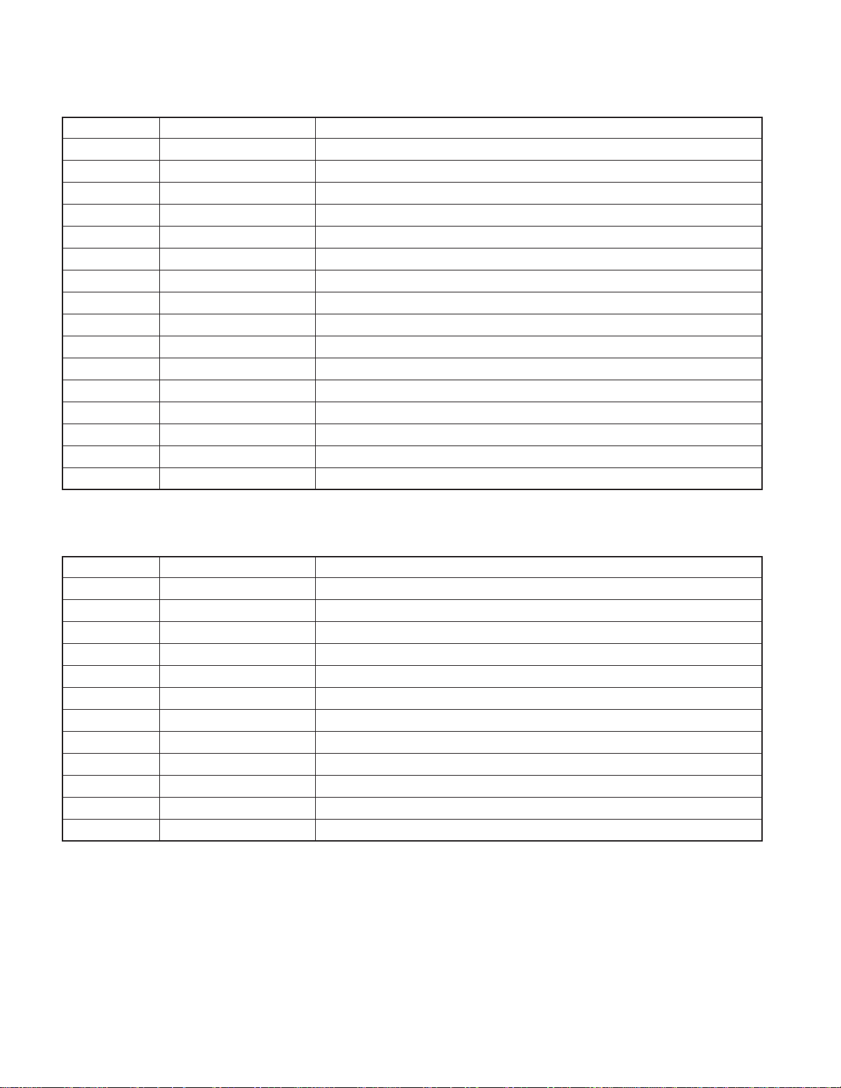
Ref. No. Application/Function Operation/Condition/Compatibility
IC101 Comparator Voltage detected
IC102 IC Voltage detected
IC103 SW regulator 8.3V power supply, 5V power source control
IC104 SW regulator 3.3V power supply, 1.5V power source control
IC105 3 terminal regulator Backup 3.3V power supply
IC106 Microcomputer Power supply, reset control
IC107 3 terminal regulator 9V power supply
IC108 3 terminal regulator 5V power supply
IC109 General purpose logic For voltage conversion from 3.3V to 5V
IC111 General purpose logic For mute signal generation
IC212 Point regulator 3V power supply
IC251 Non-inverter driver Vehicle-related signal generation
IC254 General purpose logic For SPD signal generation
IC255 Analog multiplexer For switching vehicle speed signal
IC256 General purpose logic For voltage conversion from 3.3V to 5V
IC301 Ope-amp For synthesizing voice signal
IC306 Ope-amp For voice signal for navigation system generation
IC309 General purpose logic For voltage conversion from 3.3V to 5V
IC310 Ope-amp For synthesizing voice signal
IC502 General purpose logic For voltage conversion from 3.3V to 5V
IC521 RF-IC GPS signal
IC522 Crystal oscillator For GPS signal
IC523 Comparator For GPS antenna detection
IC524~526 General purpose logic For GPS signal
IC551 General purpose logic For HDD/DVD control signal generation
IC561 General purpose logic For EJECT signal generation
IC641 D/A converter For video signal generation
IC642 General purpose logic For dot clock generation
IC684 Ope-amp For gyro sensor signal generation
IC701 Microcomputer CORE1
IC731 3 terminal regulator Backup 1.5V power supply
IC732,733 Point regulator 2.5V power supply
IC734 3 terminal regulator 1.5V power supply
IC751 Analog switch For CKE signal generation
IC752~755 128M-SDRAM 16MB
IC781 4M-SRAM 512MB
IC782,783 General purpose logic For generating CS signal
IC784 16M-FLASH 2MB
IC951 Line transceiver RS422/TMC transceiver
3
Page 4
KNA-DV3100/DV3200
COMPONENTS DESCRIPTION
Ref. No. Application/Function Operation/Condition/Compatibility
IC952 General purpose logic For generation of TMC control signal
IC954~956 General purpose logic For generation of TMC control signal
IC957 General purpose logic For mute signal generation
T101 Transistor Power ON/OFF control
T102 Power MOS FET Power ON/OFF control
T103,104 Transistor with resistor For T101&T102 control
T105,106 Transistor DC/DC switching
T107,108 Power MOS FET Power ON/OFF control
T109 Transistor with resistor For delayed ACC control
T110,111 Transistor DC/DC switching
T112,113 Transistor For backup 3.3V power supply control
T305 Transistor array For control navigation system voice mute
T306 Transistor array For control LMUTE
T307 Transistor with resistor For control beep volume
T309 Transistor with resistor For control beep volume
T319 Transistor with resistor For control T305
● DAUGHTER UNIT (X89-2622-71)
Ref. No. Application/Function Operation/Condition/Compatibility
IC1 Power supply IC 5V power supply for ACTIVE SP
IC2 AND gate Buffer for TV communicatioin (TX/RX) signal
IC3 MIC amplifier Isolation amplifier for external microphone
IC4 NAND gate For switching remote control signal (TV/Remoto control sensor)
Q1,2 Driver Mute driver
Q3 Buffer TV SYNC signal buffer
Q4 Buffer ACTIVE SP signal buffer
Q5 Mute switch RCA (Voice) Rch mute switch
Q6 Mute switch ASP (Voice) mute switch
Q7 Mute switch RCA (Voice) Lch mute switch
Q8 Mute switch TV (Voice) Lch mute switch
Q9 Mute switch TV (Voice) Rch mute switch
4
Page 5

KNA-DV3100/DV3200
MICROCOMPUTER’S TERMINAL DESCRIPTION
● MICROCOMPUTER : MB89935B (NAVI BOARD : IC106)
Pin No.
Pin Name
1 P04 O FRES output Lo : Flash ROM and CORE1 reset
2 P05 O RES output Lo : System reset
3 P06 O NMI output Interrupt output to CORE1
4 P07 I Not used (Pull down to GND line)
5 MODE0 I Mode input 0 Lo Fixed (Connect to GND Line)
6 MODE1 I Mode input 1 Lo Fixed (Connect to GND Line)
7 RST# I Reset input Lo : At the time when system is down and when panel reset SW is pressed
8X0-Clock oscillator terminal
9X1-Clock oscillator terminal
10 VSS - GND connection terminal Connect to GND line
11 P37 O P ON terminal Hi : Turning power ON for SW’s system power circuit
12 P36 I WDP input
13 P35 I ACC detection input Hi : ACC ON
14 P34 I BU detection input Hi : BU ON
15 P33 I SDRAM clock enable input Lo : Self-refresh of SDRAM, Hi : Normal operation of SDRAM
16 C - C connection terminal (0.1µF)
17 P32 I Not used (Pull down to GND line)
18 P31 I Delayed ACC input
19 P30 O ACC detection output Hi : Power ON, Lo : Power OFF (Output to CORE1 and system computer)
20 P50 O Backup operation complete notice Hi : SDRAM CKE core in control, Lo : Backup processing complete
21 AVSS - GND connection terminal Connect to GND line
22 P40 O V33D switching output Lo : Normal (ACC ON)
23 P41 O V33D switching output Lo : At the time of backup
24 P42 O Mute output Lo : Mute
25 P43 I V33 monitor input Lo : No Output
26 P00 I VMAIN monitor input Lo : No Output
27 P01 I BU monitor input Lo : No BU
28 P02 I V50 output monitor input Lo : No Output
29 P03 I V80 output monitor input Lo : No Output
30 VCC - Positive power supply terminal Connect to 3.3V line backup
I/O Function Processing Operation Description
Detection of watchdog pulse from CORE1
Normal operation : Logic is reversed within 300ms
Hi : CORE1 in operation and panel mechanism in operation when ACC is OFF
5
Page 6

KNA-DV3100/DV3200
Please insert a Map DVD.
The screen contents are to follow the HMI specifications.
Press for 5 seconds or
more on the top center
portion of the screen.
MENU
1/2
Destination
Entry
Volume
Stored
Location
Navigation
Set Up
Route Options
Language
The screen contents are to follow the HMI specifications.
Press for 5 seconds or
more on the top center
portion of the screen.
TEST MODE
Diagnostics (DIAG) Screen Flow Chart
CAUTION SCREEN
FOR NO DISK
Screen hiding
processing
ACCESS CODE
Code input
ON-SCREEN
DIAGNOSTICS
Return to a MENU
top screen
MENU SCREEN
NAVIGATION
INFORMATION
NAVI MANUAL
CHECK
PARTS
INFORMATION
GYRO, VEHICLE
SIGNALS
GPS
INFORMATION
RESET
POSITION
MICROPHONE
TEST
NAVI RGB
TEST
NAVI V OICE
OUTPUT TEST
REMOTE
CONTROL TEST
•How to move to the access code input screen using the remote controller
Press the right screen selection button for 5 seconds or
more. (No.12 b utton on the remote control test screen specification)
■ How to move to the Diag screen 2
Press for 5 seconds or more the position indicated below
while the MENU screen is displayed.
•How to move to the access code input screen using the remote controller (Overseas Market Version)
Press the right screen selection button for 5 seconds or
more. (No.12 b utton on the remote control test screen specification)
Moving to the Diagnostics (Diag) Screen
There are two ways to move to the input screen for the access code in order to move to the Diag screen. In other words ,
the access code input screen can be displayed from two different screens.
■ How to move to the Diag screen 1
Press the portion of the screen indicated below for 3 seconds or more when the Caution Screen for “No Map Disk”
is displayed.
6
Recovery from the Diag Screen
Recovery from the Diag screen can be made using the Back
swich.
Page 7

Manual Check
Navigation Info
ON-SCREEN DIAGNOSTICS
Parts Info
S/W ver : XXXX 01/29/03
Map ver : EU v99.99.99
Map ver : No MAP DVD
3
4
5
1
2
TEST MODE
KNA-DV3100/DV3200
Screen Name : Access Code input screen
■ Functions outline
• This screen is displayed after Diag operation is conducted.
• Diag screen can be accessed by inputting the Diag PIN
code in this screen.
■ Screen appearance
1
Enter Diag PIN...
■ Display details
q Displays numbers input
• The number of maximum input characters is 6.
• The numbers input from the numeric pad is displayed by
[*].
w Numeric key pad
• When the maximum input characters are input, the numbers on the numeric key pad are tone-down displayed.
e Back space key
• When no input is made, the back space key is tone-down
displayed.
r OK button
• When no input is made, the OK key is tone-down displa y ed.
• The On-screen diagnostics screen is accessed when the
appropriate code in the access level table is input.
• If the code input is not appropriate, the previous screen to
the On-screen diagnostics screen is displayed.
t The screen returns to the previous screen to the On-screen
diagnostics screen.
The Diag PIN code is defined as follows:
Diag PIN : 014220
7 8 9
4 5 6
2 3
1
0
Screen Name : On-screen diagnostics menu screen
■ Functions outline
• On-screen diagnostics screen : This is the screen to be
displayed by Diag operation.
• Data is updated when the information to be displayed
changes.
■ Screen appearance
5
3
2
OK
4
■ Display details
q The Navigation Information screen is accessed next.
w Then, the Manual Check screen is accessed.
e The Parts Information screen is accessed.
r Display of detailed information
• The version and the release date of the navigation software are displayed.
The version of navigation software : Displayed in 4 digits.
The release date of the navigation software : Displayed in
MM/DD/YY.
• The area of the map disk and version are displayed.
The area of the map disk : The area of the maps on the disk
is displayed.
The version of the map : Management Frame for all data,
Data Volume, and Media Version are displayed. When it is
considered that the map disk is not inserted, the following
characters will be displayed. “No MAP DVD” (There will be
no Area/Version display.)
t On-screen diag is ended and the screen returns to normal
operation screen. (The screen before accessing Diag
screen is to be displayed.)
7
Page 8

KNA-DV3100/DV3200
Level 0 :
Level 1 :
Level 7 :
TEST MODE
Screen Name : NAVI Manual check screen
■ Screen appearance
3 5
NAVI MANUAL CHECK
1
2
4
NAVI RGB Test
Microphone T est
■ Display details
q The button is used to access the Navi RGB test screen.
w The button is used to access the Microphone test screen.
e The button is used to access the Navi Voice output test
screen.
r The button is used to access the Remote Control test
screen.
t The button is used to return to the On-screen diagnostics
screen.
Voice Output Test
Remote Control Test
■ Display details
q The PTT connection check is conducted.
• The appropriate character set is displayed under the following condition :
<OK> : When the PTT switch is pressed.
<Please Push switch> : Other than the above.
• When <OK> is displayed, the condition is maintained. When
a different screen is accessed, the condition is released.
w Test result indicator
• Once this screen is accessed, the Navi system samples
voice at all times and sampling results are reflected on the
indicator.
• After sampling a voice in A/D, the system compares it with
the threshold value with the maximum of 500ms delay. Then,
the system makes the following displays
: Makes displays in blue if the value is greater than the
threshold value.
: Makes displays in grey if the value is smaller than the
threshold value.
e The input level of the microphone is sampled every 200ms
and the results are displayed on 8 levels. The display update timing for the input level is 400ms.
Screen Name : Micr ophone inspection screen
■ Functions outline
• PTT connection conformation of the voice recognition microphone and microphone check.
■ Screen appearance
MICROPHONE TEST
PTT switch status:
Please Speak at a Normal Level into the Microphone.
Microphone input level judging.
Microphone level :
< Please Push switch >
4
1
2
3
r When terminated, the screen goes back to the NAVI Man ual
check screen.
8
Page 9

ON (Max)
ON (Normal)
NA VI VOICE OUTPUT TEST
ADPCM:
3
2
1
TEST MODE
KNA-DV3100/DV3200
Screen Name : NAVI RGB test screen
■ Functions outline
•This is the screen for testing the NAVI color display.
■ Screen appearance
2
NAVI RGB TEST
1
3
White blackRed Green blue
A color buttons is
chosen.
The selected color is
displayed on the whole
screen.
Screen Name : NAVI Voice Output test screen
■ Functions outline
• In this screen, the ADPCM output is tested.
■ Screen appearance
4
■ Display details
q and w are ADPCM voice test buttons.
• The following ADPCM voices (sine w av e of 1kHz/maxim um
since wave of 1kHz) are output for five seconds.
NORMAL (q) Voice ID : 00020015
MAX (w) Voice ID : 00020014
Howev er , if no map disk is not inserted, the ADPCM voices
are not output.
e When terminated, the screen goes back to the NAVI Man ual
check screen.
■ Display details
q Color bar
• Bar display for the following colors : white, red, green, blue
and black.
w Selection button
• When a button corresponding to a color is pressed, the
selected color is displayed on the whole screen.
e Whole screen display
• The selected color is displayed on the whole screen.
• When other parts of the screen is pressed, the screen goes
back to the RGB test screen.
r When terminated, the screen goes back to the NAVI Man ual
check screen.
Touch screen
• In this screen, the beep is not sounded when q and w buttons are pressed.
9
Page 10

KNA-DV3100/DV3200
TEST MODE
Screen Name : Remote control test screen
■ Functions outline
• In this screen, remote control buttons are tested.
■ Screen appearance
REMOTE CONTROL TEST
Please push the remote control buttons.
SW Name
When a back button is pushed,
returns to a previous screen.
1~9
10~12
16
13
29
33
35
38
■ Display details
q Names of button switches
• When a remote control button switch is pressed, the name
of the button is display ed within the frame . (Please refer to
the definition for the button names in the table right.)
• When this screen is first accessed, the display frame will
be blank. When the button is pressed and while it is depressed, the corresponding button name will be displayed.
When the button is released, the display disappears. (Blank)
• When the cancel button is pressed, the switch name will
not be displayed and the screen goes back to the NAVI
Manual Check screen.
• When a remote control button is pressed, a beep sounds.
w The screen goes back to the NAVI Manual Check screen.
is being pushed
14
15
31
34
37
17~28
2
1
■ Definitions of the Button Names
The table below is the correspondence table between the
remote control silk names and displayed names on the diag
screen. For detail, refer to the Car Navigation System Remote
Control Software specifications.
No. ID Function Display Name
14A0° (Up) UP
24B45° (Upper right) UPPER RIGHT
34C90° (Right) RIGHT
44D135° (Lower right) LOWER RIGHT
54E180° (Down) DOWN
64F225° (Lower lift) LOWER LEFT
750270° (Left) LEFT
851315° (Upper left) UPPER LEFT
95AENT ENT
10 82 ZOOM OUT
11 83 ZOOM IN
12 16 Right screen select RIGHT SELECT
13 84 Position POSITION
14 5D Menu MENU
15 80 Route ROUTE
16 D6 Cancel CANCEL
17 41 1 1
18 42 2 (ABC) 2
19 43 3 (DEF) 3
20 44 4 (GHI) 4
21 45 5 (JKL) 5
22 46 6 (MNO) 6
23 47 7 (PQRS) 7
24 48 8 (TUV) 8
25 49 9 (WXYZ) 9
26 40 0 (Space) 0
27 10 * (+) *
28 CB # (BS) #
29 17 Voice VOICE
31 C1 Short cut 1 SHORT CUT 1
33 D9 ↑ List UP LIST
34 C2 Shot cut 2 SHORT CUT 2
35 DA ← Text LEFT TEXT
37 DC → Text RIGHT TEXT
38 DD ↓ List DOWN LIST
No. 1~16 : Not related to whether the cover is open or closed.
No. 17~28 : Cover open
No. 29~40 : Cover closed
<>
10
Page 11

TEST MODE
KNA-DV3100/DV3200
Screen Name : Na vigation information screen
■ Screen appearance
2 4
NAVIGATION INFO
1
3
■ Display details
q VEHICLE/GYRO/SIGNALS screen is accessed.
w GPS information screen is accessed.
e Reset Position screen is accessed.
r The screen returns to the On-screen diagnostics screen.
Vehicle Signals
Reset Position
GPS Information
Screen Name : Vehicle signals screen
■ Functions outline
• In this screen, the vehicle signals input to the Navi ECU are
checked.
• The data is updated when the information changes.
■ Screen appearance
VEHICLE/GYRO SIGNALS
Vehicle Info.
ILL: ON
Speed (kph,mpk)
SPD Pulse Count
Distance Calibration (mm)
Gyro Info.
Voltage / Offset (mV)
Relative Bearing (° )
Gyro Sense
PKB: ON REV: OFF
: 160, 100
: XXXXX
: 200
: 2500, 2495
: 359.0
: 1.000
Reset
11
3
4
5
6
7
8
10
■ Display details
q When ILL signal is displayed :
• The condition of the PARK LAMP is displayed as : ON/OFF.
w When PKB signal is displayed :
• The condition of the parking brake signal is displayed as :
ON/OFF
e When REV signal is displayed :
• The condition of the REV signal is displayed as : ON/OFF.
r Vehicle speed condition
• The vehicle speed is displayed in kph/mph.
The speed is displayed in maximum of 3 digits in LSB 1.
t The count value of the SPD pulses is display ed. (The time
of access to the screen is set to 0. The count is displayed
in maximum of 5 digits in LSB 1 with the maximum of 65535
and when this is exceeded, the value is counted again from
0.)
y Distance adjustment information
• The obtained value is displayed.
The value is displayed in maximum of 3 digits in LSB 1.
u, i, o Gyro signal display
• Gyro output voltage value is displayed in mV.
The value is displayed in maximum of 4 digits in LSB with
1mV as the unit.
• Gyro output voltage value (left) and adjusted ref erence v oltage (right) are displayed in mV.
The value is displayed in maximum of 4 digits in LSB with
1mV as the unit.
• The relative direction is display ed. (The time when the Na vi
system is activated is set to 0.)
The value is displayed in maximum of 4 digits in LSB with
0.1 degree as the unit.
• The obtained value for the gyro sensitivity is displayed.
The value is displayed in maximum of 4 digits in LSB with
0.011 as the unit.
!0 Reset button for the gyro sensitivity obtained value
• This button is for resetting the gyro sensitivity obtained value .
!1 The screen returns to the Navigation Information screen.
2 91
11
Page 12

KNA-DV3100/DV3200
TEST MODE
Screen Name : GPS information screen
■ Functions outline
• This screen displays GPS-related information.
• The data is updated when the information displayed
changes.
■ Screen appearance
GPS INFORMATION
ID Elv/Azm St Lev
1 10° /010° P52
2 20° /020° T49
3 30° /030° –0
4 40° /040° P49
5 70° /300° –0
6 89° /359° –0
Data (GMT): 12/31/2002 09:46:59 HDOP: xx.x
Latitude Longitude Meas. Stat : 3D
N34° 59´ 5˝ E137° 30´ 11˝
32 4
■ Display details
q Satellite information
• The following information on the satellite as the search object is displayed : satellite number (ID); an angle of elevation (Elv); azimuth reading (Azm); signal level (Lev) and reception state (St).
• The display areas are secured for the maximum of 8 satellites.
•For the reception state, the appropriate letter is displayed
depending on the state.
[P] : When the satellite in question is used for positioning.
[T] : When the satellite in question is spotted but not used
for positioning.
[–] : When the satellite in question is spotted yet.
w Date and time information
• The date and time information obtained from the GPS receiver is displayed in : month; day; year; hour; minute; and
second.
e Position information
• The current latitude and longitude are displayed in : sign,
degree, minute, and second.
As for the sign, appropriate letter is displayed according to
the conditions that apply.
[N] : When the latitude is judged to be north latitude.
[S] : When the latitude is judged to be south latitude.
[W] : When the longitude is judged to be west longitude.
[E] : When the longitude is judged to be east longitude.
r Positioning condition information
•Positioning conditions are described in the following five
conditions :
12
ID Elv/Azm St Lev
20 53° /256° P50
15 11° /111° T49
[2D] : When positioning is made on two dimensions.
[3D] : When positioning is made on three dimensions.
[NG] : When positioning is not possible..
[error] : When reception error takes place.
[–] : When conditions other than the above occur.
t HDOP
• The HDOP value at the time of positioning (accuracy value
in the horizontal direction) is displayed in numbers.
6
1
LSB 01 display areas: 0.0~99.9
When exceeding 99.9 and when positioning is not conducted, [–] is displayed.
y The screen returns to the Navigation Information screen.
5
Screen Name : Adjust position screen
■ Functions outline
• This is the function for adjusting the position to the default
coordinate that is registered on the map disk.
■ Screen appearance
Reset Position
RESET POSITION
Map DVD is
inserted
No
Yes
Please press the ‘Reset’ button to reset the vehicle
position to the current map DVD default.
Reset
Adjust the current position.
Return to the Navigation
Information screen.
Map DVD is inserted
RESET POSITION
Please insert a map DVD to arrow vehicle position
be reset to the current map DVD default.
Reset
Reset
Make the direction of
the vehicle to 0 degree
(for east).
1
1
■ Display details
q The screen returns to the Navigation Information screen.
Page 13

TEST MODE
KNA-DV3100/DV3200
Screen Name : Parts information screen
■ Functions outline
• Displays the conditions of the parts comprising the navigation system.
• Displays the map software version of the navigation system.
• The data updates are conducted when the information
changes.
■ Screen appearance
PARTS INFORMATION
NAVI : XXXX
LODER : XXXX
DVD : XX.XX
Disc Information
FORMAT_VERSION_KIWI01-06-00
DATA_VERSION_01-00001
GPS :
Traffic system :
Fitted
None
5
2
1
3
4
■ Display details
q Displays the map software version of the softw are that com-
prise navigation system.
•NAVI : Displays the software version of the software that
comprise navigation system.
• LODER : Displays the kanji ROM version.
•DVD : Displays the revision level of the DVD player.
w Displays the conditions of the devices that comprise the
navigation system.
• GPS: The connection condition of the GPS system is displayed by appropr iate character sets that corresponds to
the condition :
[Fitted] : GPS antenna is connected.
[None] : Conditions other than the above.
• The type of traffic congestion information service is displayed by appropr iate character sets that corresponds to
the condition :
[TMC] : When a TMC tuner is connected.
[None] : Conditions other than the above.
e Format version number
• Displays the data stored in the “For mat Version Number”
item in the “Control Frame Data Volume for all data” on the
disk.
r Data V ersion Number
• Displays the data stored in the “Data Version Number” item
in the “Control F rame Data Volume for all data” on the disk.
t The screen returns to the On-screen diagnostics screen.
13
 Loading...