

Page 1
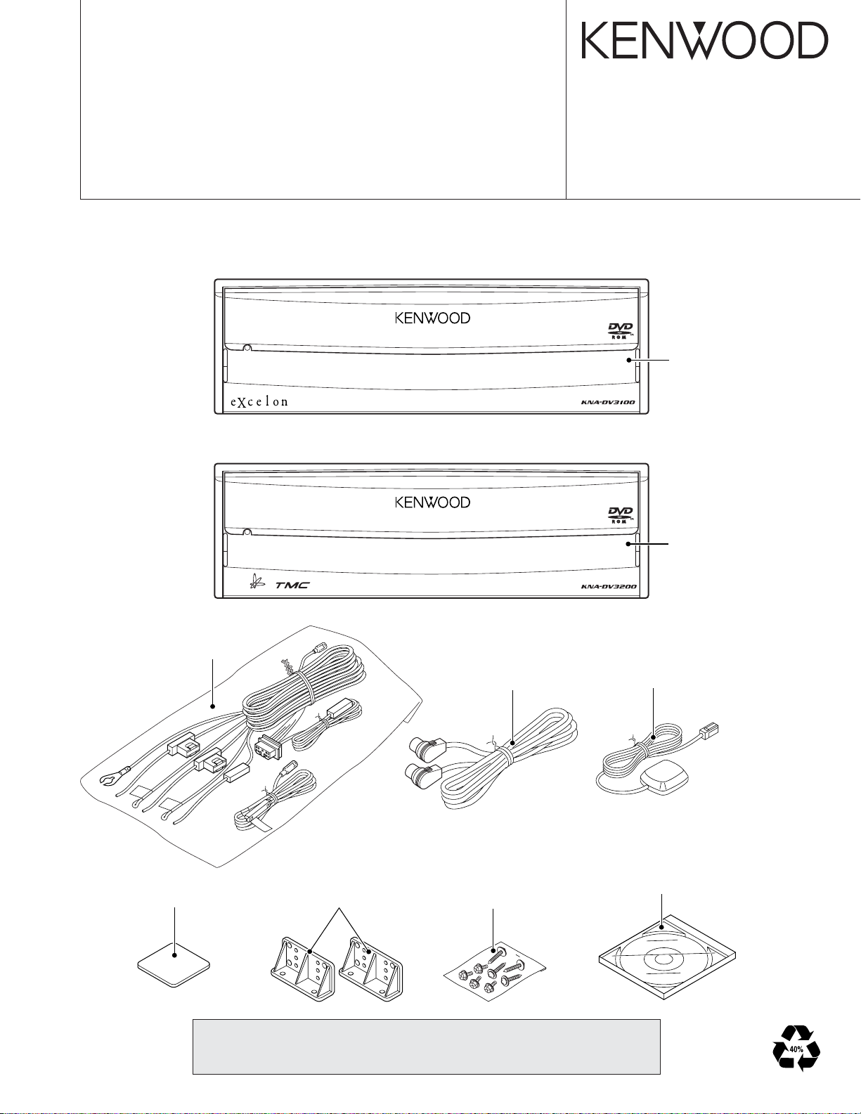
DVD NAVIGATION SYSTEM
KNA-DV3100
KNA-DV3200
SERVICE MANUAL
The DVD mechanism infomation is not in this sarvice manual.
Please, refer to sarvice manual X92-4740-00 (B53-0052-00).
KNA-DV3100
© 2003-4 PRINTED IN JAPAN
B53-0050-00 (N) 3100
Panel assy
(A64-3105-03)
KNA-DV3200
DC cord assy
(E30-4964-05)
Mounting hardware
(J21-9867-04)
Bracket
(J19-5246-04)
Connecting cord assy
(E30-6199-05)
Screw set
(N99-1713-05)
Panel assy
(A64-3106-03)
Electric circuit module (GPS ANT)
(W02-3261-05)
DVD
(W01-1618-05) : KNA-DV3100
(W01-1619-05) : KNA-DV3200
CAUTION (Repair of NAVI board )
You can not repair IC521 (GPS Receiver) and IC701 (CORE1).
If you can repair those parts please change to NAVI board assy(W02-3395-15).
Page 2

2
SDRAM
64MB
FLASH
2MB
SRAM
512kB
VEHICLE
GPS RF
SPD,REV,ILL,PKB
GPS
GYRO
CORE1
A351
IC251,254,255
IC521
IC701
SIGNAL I/F
IC752-755
IC781
IC784
DVD
MECHANISM
RECOGNITION I/F
VOICE
DISPLAY
COMMUNICATION
RGB
ENCODER
OUTPUT I/F
VOICE
CONTROL
REMOTE
I/F
RS-422
SW
MIC & SW
MONITOR
MONITOR
RCA
MONITOR
RCA
ASP
TMC
RESET SW
EJECT SW
REMOTE
CONTROL
9V,8V,5V,
POWER SUPPLY
3.3V,2.5V,1.5V
IC641
IC952-956
(DIGITAL)
NAVI RGB
BEEP
NAVIVOICE
NAVI RGB
NTSC
GYRO PCB
(X25-974)
NAVI UNIT (W02-3395-05)
SUB UNIT (X89-262)
SW PCB (X25-974)
KNA-DV3100/DV3200
BLOCK DIAGRAM
Page 3

KNA-DV3100/DV3200
COMPONENTS DESCRIPTION
● NAVI BOARD (W02-3395-15)
Ref. No. Application/Function Operation/Condition/Compatibility
IC101 Comparator Voltage detected
IC102 IC Voltage detected
IC103 SW regulator 8.3V power supply, 5V power source control
IC104 SW regulator 3.3V power supply, 1.5V power source control
IC105 3 terminal regulator Backup 3.3V power supply
IC106 Microcomputer Power supply, reset control
IC107 3 terminal regulator 9V power supply
IC108 3 terminal regulator 5V power supply
IC109 General purpose logic For voltage conversion from 3.3V to 5V
IC111 General purpose logic For mute signal generation
IC212 Point regulator 3V power supply
IC251 Non-inverter driver Vehicle-related signal generation
IC254 General purpose logic For SPD signal generation
IC255 Analog multiplexer For switching vehicle speed signal
IC256 General purpose logic For voltage conversion from 3.3V to 5V
IC301 Ope-amp For synthesizing voice signal
IC306 Ope-amp For voice signal for navigation system generation
IC309 General purpose logic For voltage conversion from 3.3V to 5V
IC310 Ope-amp For synthesizing voice signal
IC502 General purpose logic For voltage conversion from 3.3V to 5V
IC521 RF-IC GPS signal
IC522 Crystal oscillator For GPS signal
IC523 Comparator For GPS antenna detection
IC524~526 General purpose logic For GPS signal
IC551 General purpose logic For HDD/DVD control signal generation
IC561 General purpose logic For EJECT signal generation
IC641 D/A converter For video signal generation
IC642 General purpose logic For dot clock generation
IC684 Ope-amp For gyro sensor signal generation
IC701 Microcomputer CORE1
IC731 3 terminal regulator Backup 1.5V power supply
IC732,733 Point regulator 2.5V power supply
IC734 3 terminal regulator 1.5V power supply
IC751 Analog switch For CKE signal generation
IC752~755 128M-SDRAM 16MB
IC781 4M-SRAM 512MB
IC782,783 General purpose logic For generating CS signal
IC784 16M-FLASH 2MB
IC951 Line transceiver RS422/TMC transceiver
3
Page 4
KNA-DV3100/DV3200
COMPONENTS DESCRIPTION
Ref. No. Application/Function Operation/Condition/Compatibility
IC952 General purpose logic For generation of TMC control signal
IC954~956 General purpose logic For generation of TMC control signal
IC957 General purpose logic For mute signal generation
T101 Transistor Power ON/OFF control
T102 Power MOS FET Power ON/OFF control
T103,104 Transistor with resistor For T101&T102 control
T105,106 Transistor DC/DC switching
T107,108 Power MOS FET Power ON/OFF control
T109 Transistor with resistor For delayed ACC control
T110,111 Transistor DC/DC switching
T112,113 Transistor For backup 3.3V power supply control
T305 Transistor array For control navigation system voice mute
T306 Transistor array For control LMUTE
T307 Transistor with resistor For control beep volume
T309 Transistor with resistor For control beep volume
T319 Transistor with resistor For control T305
● DAUGHTER UNIT (X89-2622-71)
Ref. No. Application/Function Operation/Condition/Compatibility
IC1 Power supply IC 5V power supply for ACTIVE SP
IC2 AND gate Buffer for TV communicatioin (TX/RX) signal
IC3 MIC amplifier Isolation amplifier for external microphone
IC4 NAND gate For switching remote control signal (TV/Remoto control sensor)
Q1,2 Driver Mute driver
Q3 Buffer TV SYNC signal buffer
Q4 Buffer ACTIVE SP signal buffer
Q5 Mute switch RCA (Voice) Rch mute switch
Q6 Mute switch ASP (Voice) mute switch
Q7 Mute switch RCA (Voice) Lch mute switch
Q8 Mute switch TV (Voice) Lch mute switch
Q9 Mute switch TV (Voice) Rch mute switch
4
Page 5

KNA-DV3100/DV3200
MICROCOMPUTER’S TERMINAL DESCRIPTION
● MICROCOMPUTER : MB89935B (NAVI BOARD : IC106)
Pin No.
Pin Name
1 P04 O FRES output Lo : Flash ROM and CORE1 reset
2 P05 O RES output Lo : System reset
3 P06 O NMI output Interrupt output to CORE1
4 P07 I Not used (Pull down to GND line)
5 MODE0 I Mode input 0 Lo Fixed (Connect to GND Line)
6 MODE1 I Mode input 1 Lo Fixed (Connect to GND Line)
7 RST# I Reset input Lo : At the time when system is down and when panel reset SW is pressed
8X0-Clock oscillator terminal
9X1-Clock oscillator terminal
10 VSS - GND connection terminal Connect to GND line
11 P37 O P ON terminal Hi : Turning power ON for SW’s system power circuit
12 P36 I WDP input
13 P35 I ACC detection input Hi : ACC ON
14 P34 I BU detection input Hi : BU ON
15 P33 I SDRAM clock enable input Lo : Self-refresh of SDRAM, Hi : Normal operation of SDRAM
16 C - C connection terminal (0.1µF)
17 P32 I Not used (Pull down to GND line)
18 P31 I Delayed ACC input
19 P30 O ACC detection output Hi : Power ON, Lo : Power OFF (Output to CORE1 and system computer)
20 P50 O Backup operation complete notice Hi : SDRAM CKE core in control, Lo : Backup processing complete
21 AVSS - GND connection terminal Connect to GND line
22 P40 O V33D switching output Lo : Normal (ACC ON)
23 P41 O V33D switching output Lo : At the time of backup
24 P42 O Mute output Lo : Mute
25 P43 I V33 monitor input Lo : No Output
26 P00 I VMAIN monitor input Lo : No Output
27 P01 I BU monitor input Lo : No BU
28 P02 I V50 output monitor input Lo : No Output
29 P03 I V80 output monitor input Lo : No Output
30 VCC - Positive power supply terminal Connect to 3.3V line backup
I/O Function Processing Operation Description
Detection of watchdog pulse from CORE1
Normal operation : Logic is reversed within 300ms
Hi : CORE1 in operation and panel mechanism in operation when ACC is OFF
5
Page 6
KNA-DV3100/DV3200
Please insert a Map DVD.
The screen contents are to follow the HMI specifications.
Press for 5 seconds or
more on the top center
portion of the screen.
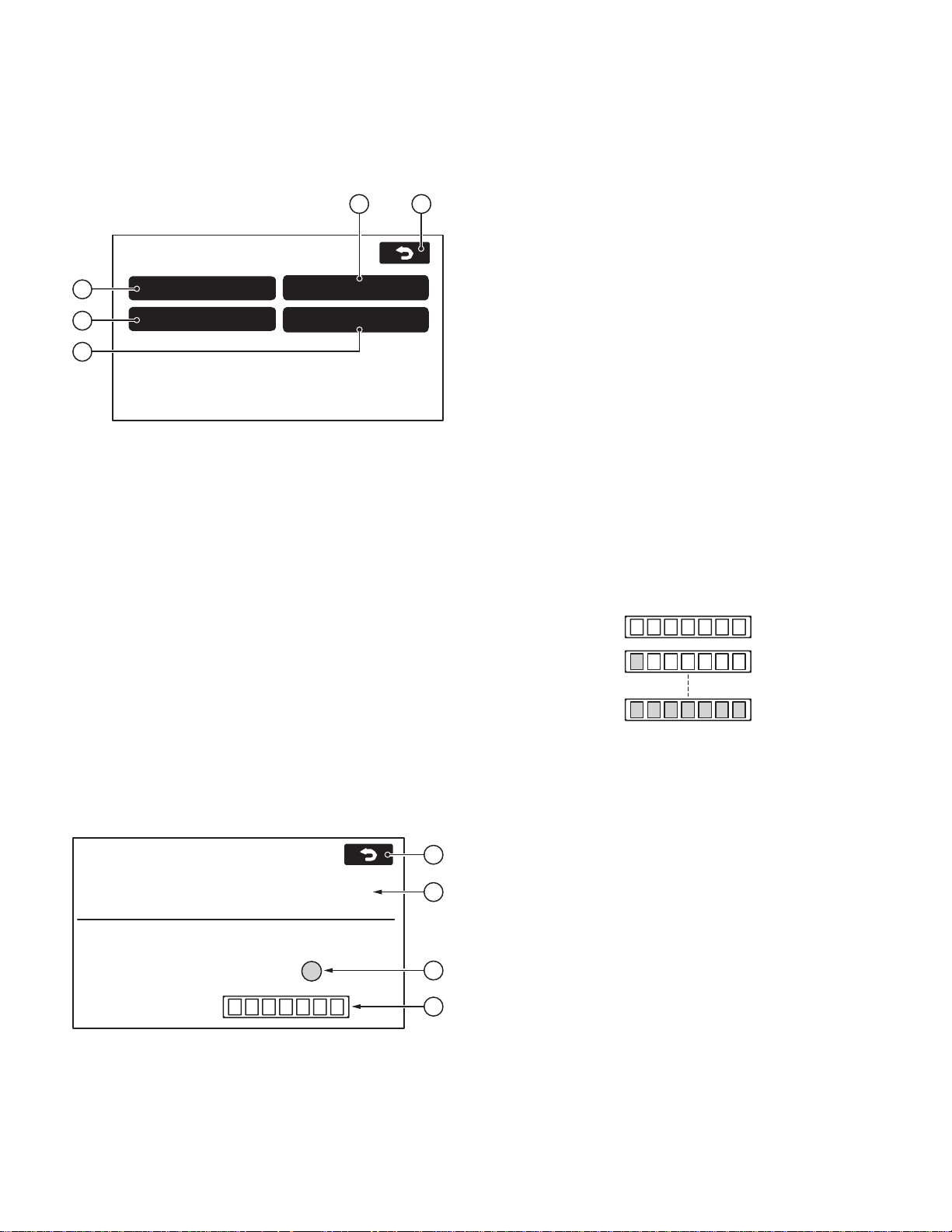
MENU
1/2
Destination
Entry
Volume
Stored
Location
Navigation
Set Up
Route Options
Language
The screen contents are to follow the HMI specifications.
Press for 5 seconds or
more on the top center
portion of the screen.
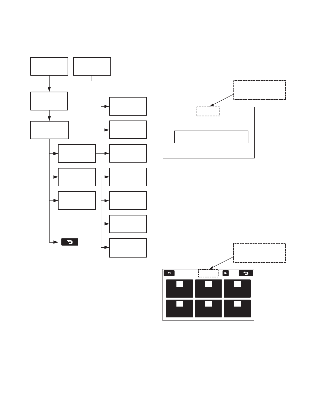
TEST MODE
Diagnostics (DIAG) Screen Flow Chart
CAUTION SCREEN
FOR NO DISK
Screen hiding
processing
ACCESS CODE
Code input
ON-SCREEN
DIAGNOSTICS
Return to a MENU
top screen
MENU SCREEN
NAVIGATION
INFORMATION
NAVI MANUAL
CHECK
PARTS
INFORMATION
GYRO, VEHICLE
SIGNALS
GPS
INFORMATION
RESET
POSITION
MICROPHONE
TEST
NAVI RGB
TEST
NAVI V OICE
OUTPUT TEST
REMOTE
CONTROL TEST
•How to move to the access code input screen using the remote controller
Press the right screen selection button for 5 seconds or
more. (No.12 b utton on the remote control test screen specification)
■ How to move to the Diag screen 2
Press for 5 seconds or more the position indicated below
while the MENU screen is displayed.
•How to move to the access code input screen using the remote controller (Overseas Market Version)
Press the right screen selection button for 5 seconds or
more. (No.12 b utton on the remote control test screen specification)
Moving to the Diagnostics (Diag) Screen
There are two ways to move to the input screen for the access code in order to move to the Diag screen. In other words ,
the access code input screen can be displayed from two different screens.
■ How to move to the Diag screen 1
Press the portion of the screen indicated below for 3 seconds or more when the Caution Screen for “No Map Disk”
is displayed.
6
Recovery from the Diag Screen
Recovery from the Diag screen can be made using the Back
swich.
Page 7
Manual Check
Navigation Info
ON-SCREEN DIAGNOSTICS
Parts Info
S/W ver : XXXX 01/29/03
Map ver : EU v99.99.99
Map ver : No MAP DVD
3
4
5
1
2
TEST MODE
KNA-DV3100/DV3200
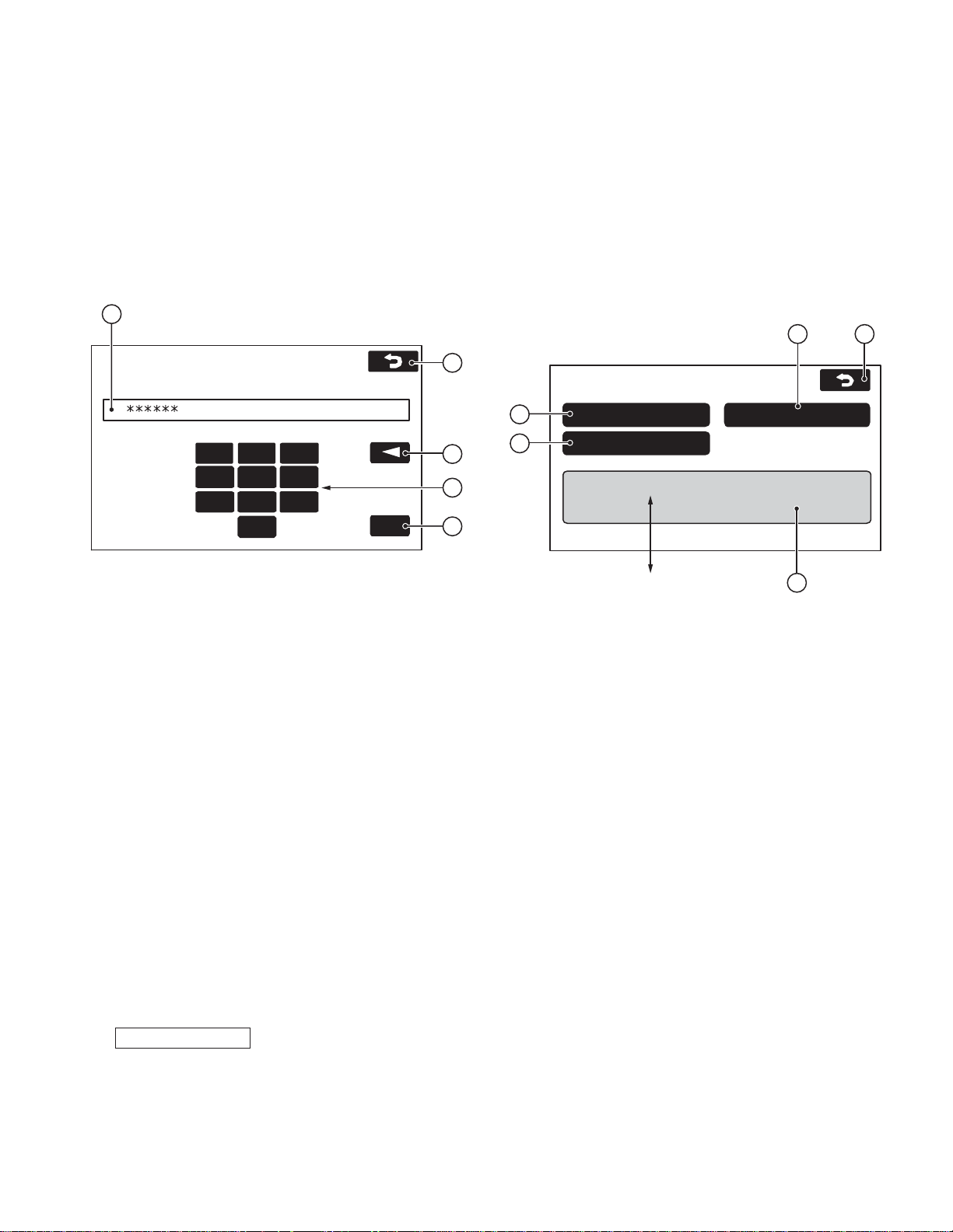
Screen Name : Access Code input screen
■ Functions outline
• This screen is displayed after Diag operation is conducted.
• Diag screen can be accessed by inputting the Diag PIN
code in this screen.
■ Screen appearance
1
Enter Diag PIN...
■ Display details
q Displays numbers input
• The number of maximum input characters is 6.
• The numbers input from the numeric pad is displayed by
[*].
w Numeric key pad
• When the maximum input characters are input, the numbers on the numeric key pad are tone-down displayed.
e Back space key
• When no input is made, the back space key is tone-down
displayed.
r OK button
• When no input is made, the OK key is tone-down displa y ed.
• The On-screen diagnostics screen is accessed when the
appropriate code in the access level table is input.
• If the code input is not appropriate, the previous screen to
the On-screen diagnostics screen is displayed.
t The screen returns to the previous screen to the On-screen
diagnostics screen.
The Diag PIN code is defined as follows:
Diag PIN : 014220
7 8 9
4 5 6
2 3
1
0
Screen Name : On-screen diagnostics menu screen
■ Functions outline
• On-screen diagnostics screen : This is the screen to be
displayed by Diag operation.
• Data is updated when the information to be displayed
changes.
■ Screen appearance
5
3
2
OK
4
■ Display details
q The Navigation Information screen is accessed next.
w Then, the Manual Check screen is accessed.
e The Parts Information screen is accessed.
r Display of detailed information
• The version and the release date of the navigation software are displayed.
The version of navigation software : Displayed in 4 digits.
The release date of the navigation software : Displayed in
MM/DD/YY.
• The area of the map disk and version are displayed.
The area of the map disk : The area of the maps on the disk
is displayed.
The version of the map : Management Frame for all data,
Data Volume, and Media Version are displayed. When it is
considered that the map disk is not inserted, the following
characters will be displayed. “No MAP DVD” (There will be
no Area/Version display.)
t On-screen diag is ended and the screen returns to normal
operation screen. (The screen before accessing Diag
screen is to be displayed.)
7
Page 8
KNA-DV3100/DV3200
Level 0 :
Level 1 :
Level 7 :
TEST MODE
Screen Name : NAVI Manual check screen
■ Screen appearance
3 5
NAVI MANUAL CHECK
1
2
4
NAVI RGB Test
Microphone T est
■ Display details
q The button is used to access the Navi RGB test screen.
w The button is used to access the Microphone test screen.
e The button is used to access the Navi Voice output test
screen.
r The button is used to access the Remote Control test
screen.
t The button is used to return to the On-screen diagnostics
screen.
Voice Output Test
Remote Control Test
■ Display details
q The PTT connection check is conducted.
• The appropriate character set is displayed under the following condition :
<OK> : When the PTT switch is pressed.
<Please Push switch> : Other than the above.
• When <OK> is displayed, the condition is maintained. When
a different screen is accessed, the condition is released.
w Test result indicator
• Once this screen is accessed, the Navi system samples
voice at all times and sampling results are reflected on the
indicator.
• After sampling a voice in A/D, the system compares it with
the threshold value with the maximum of 500ms delay. Then,
the system makes the following displays
: Makes displays in blue if the value is greater than the
threshold value.
: Makes displays in grey if the value is smaller than the
threshold value.
e The input level of the microphone is sampled every 200ms
and the results are displayed on 8 levels. The display update timing for the input level is 400ms.
Screen Name : Micr ophone inspection screen
■ Functions outline
• PTT connection conformation of the voice recognition microphone and microphone check.
■ Screen appearance
MICROPHONE TEST
PTT switch status:
Please Speak at a Normal Level into the Microphone.
Microphone input level judging.
Microphone level :
< Please Push switch >
4
1
2
3
r When terminated, the screen goes back to the NAVI Man ual
check screen.
8
Page 9
ON (Max)
ON (Normal)
NA VI VOICE OUTPUT TEST
ADPCM:
3
2
1
TEST MODE
KNA-DV3100/DV3200
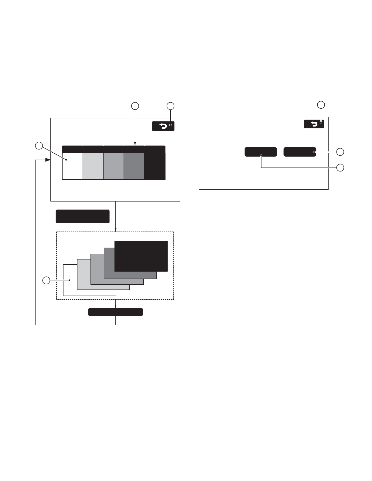
Screen Name : NAVI RGB test screen
■ Functions outline
•This is the screen for testing the NAVI color display.
■ Screen appearance
2
NAVI RGB TEST
1
3
White blackRed Green blue
A color buttons is
chosen.
The selected color is
displayed on the whole
screen.
Screen Name : NAVI Voice Output test screen
■ Functions outline
• In this screen, the ADPCM output is tested.
■ Screen appearance
4
■ Display details
q and w are ADPCM voice test buttons.
• The following ADPCM voices (sine w av e of 1kHz/maxim um
since wave of 1kHz) are output for five seconds.
NORMAL (q) Voice ID : 00020015
MAX (w) Voice ID : 00020014
Howev er , if no map disk is not inserted, the ADPCM voices
are not output.
e When terminated, the screen goes back to the NAVI Man ual
check screen.
■ Display details
q Color bar
• Bar display for the following colors : white, red, green, blue
and black.
w Selection button
• When a button corresponding to a color is pressed, the
selected color is displayed on the whole screen.
e Whole screen display
• The selected color is displayed on the whole screen.
• When other parts of the screen is pressed, the screen goes
back to the RGB test screen.
r When terminated, the screen goes back to the NAVI Man ual
check screen.
Touch screen
• In this screen, the beep is not sounded when q and w buttons are pressed.
9
Page 10
KNA-DV3100/DV3200
TEST MODE
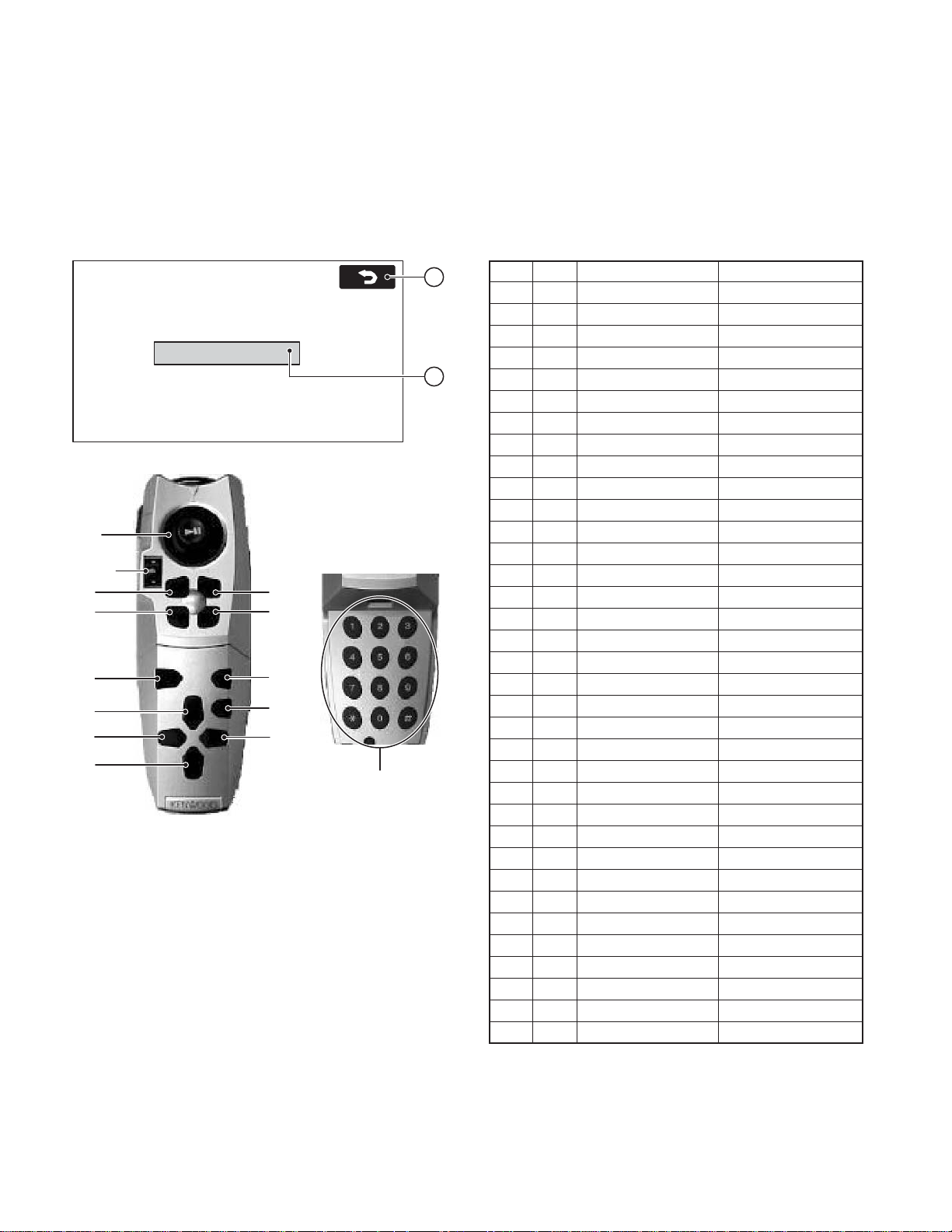
Screen Name : Remote control test screen
■ Functions outline
• In this screen, remote control buttons are tested.
■ Screen appearance
REMOTE CONTROL TEST
Please push the remote control buttons.
SW Name
When a back button is pushed,
returns to a previous screen.
1~9
10~12
16
13
29
33
35
38
■ Display details
q Names of button switches
• When a remote control button switch is pressed, the name
of the button is display ed within the frame . (Please refer to
the definition for the button names in the table right.)
• When this screen is first accessed, the display frame will
be blank. When the button is pressed and while it is depressed, the corresponding button name will be displayed.
When the button is released, the display disappears. (Blank)
• When the cancel button is pressed, the switch name will
not be displayed and the screen goes back to the NAVI
Manual Check screen.
• When a remote control button is pressed, a beep sounds.
w The screen goes back to the NAVI Manual Check screen.
is being pushed
14
15
31
34
37
17~28
2
1
■ Definitions of the Button Names
The table below is the correspondence table between the
remote control silk names and displayed names on the diag
screen. For detail, refer to the Car Navigation System Remote
Control Software specifications.
No. ID Function Display Name
14A0° (Up) UP
24B45° (Upper right) UPPER RIGHT
34C90° (Right) RIGHT
44D135° (Lower right) LOWER RIGHT
54E180° (Down) DOWN
64F225° (Lower lift) LOWER LEFT
750270° (Left) LEFT
851315° (Upper left) UPPER LEFT
95AENT ENT
10 82 ZOOM OUT
11 83 ZOOM IN
12 16 Right screen select RIGHT SELECT
13 84 Position POSITION
14 5D Menu MENU
15 80 Route ROUTE
16 D6 Cancel CANCEL
17 41 1 1
18 42 2 (ABC) 2
19 43 3 (DEF) 3
20 44 4 (GHI) 4
21 45 5 (JKL) 5
22 46 6 (MNO) 6
23 47 7 (PQRS) 7
24 48 8 (TUV) 8
25 49 9 (WXYZ) 9
26 40 0 (Space) 0
27 10 * (+) *
28 CB # (BS) #
29 17 Voice VOICE
31 C1 Short cut 1 SHORT CUT 1
33 D9 ↑ List UP LIST
34 C2 Shot cut 2 SHORT CUT 2
35 DA ← Text LEFT TEXT
37 DC → Text RIGHT TEXT
38 DD ↓ List DOWN LIST
No. 1~16 : Not related to whether the cover is open or closed.
No. 17~28 : Cover open
No. 29~40 : Cover closed
<>
10
Page 11

TEST MODE
KNA-DV3100/DV3200
Screen Name : Na vigation information screen
■ Screen appearance
2 4
NAVIGATION INFO
1
3
■ Display details
q VEHICLE/GYRO/SIGNALS screen is accessed.
w GPS information screen is accessed.
e Reset Position screen is accessed.
r The screen returns to the On-screen diagnostics screen.
Vehicle Signals
Reset Position
GPS Information
Screen Name : Vehicle signals screen
■ Functions outline
• In this screen, the vehicle signals input to the Navi ECU are
checked.
• The data is updated when the information changes.
■ Screen appearance
VEHICLE/GYRO SIGNALS
Vehicle Info.
ILL: ON
Speed (kph,mpk)
SPD Pulse Count
Distance Calibration (mm)
Gyro Info.
Voltage / Offset (mV)
Relative Bearing (° )
Gyro Sense
PKB: ON REV: OFF
: 160, 100
: XXXXX
: 200
: 2500, 2495
: 359.0
: 1.000
Reset
11
3
4
5
6
7
8
10
■ Display details
q When ILL signal is displayed :
• The condition of the PARK LAMP is displayed as : ON/OFF.
w When PKB signal is displayed :
• The condition of the parking brake signal is displayed as :
ON/OFF
e When REV signal is displayed :
• The condition of the REV signal is displayed as : ON/OFF.
r Vehicle speed condition
• The vehicle speed is displayed in kph/mph.
The speed is displayed in maximum of 3 digits in LSB 1.
t The count value of the SPD pulses is display ed. (The time
of access to the screen is set to 0. The count is displayed
in maximum of 5 digits in LSB 1 with the maximum of 65535
and when this is exceeded, the value is counted again from
0.)
y Distance adjustment information
• The obtained value is displayed.
The value is displayed in maximum of 3 digits in LSB 1.
u, i, o Gyro signal display
• Gyro output voltage value is displayed in mV.
The value is displayed in maximum of 4 digits in LSB with
1mV as the unit.
• Gyro output voltage value (left) and adjusted ref erence v oltage (right) are displayed in mV.
The value is displayed in maximum of 4 digits in LSB with
1mV as the unit.
• The relative direction is display ed. (The time when the Na vi
system is activated is set to 0.)
The value is displayed in maximum of 4 digits in LSB with
0.1 degree as the unit.
• The obtained value for the gyro sensitivity is displayed.
The value is displayed in maximum of 4 digits in LSB with
0.011 as the unit.
!0 Reset button for the gyro sensitivity obtained value
• This button is for resetting the gyro sensitivity obtained value .
!1 The screen returns to the Navigation Information screen.
2 91
11
Page 12

KNA-DV3100/DV3200
TEST MODE
Screen Name : GPS information screen
■ Functions outline
• This screen displays GPS-related information.
• The data is updated when the information displayed
changes.
■ Screen appearance
GPS INFORMATION
ID Elv/Azm St Lev
1 10° /010° P52
2 20° /020° T49
3 30° /030° –0
4 40° /040° P49
5 70° /300° –0
6 89° /359° –0
Data (GMT): 12/31/2002 09:46:59 HDOP: xx.x
Latitude Longitude Meas. Stat : 3D
N34° 59´ 5˝ E137° 30´ 11˝
32 4
■ Display details
q Satellite information
• The following information on the satellite as the search object is displayed : satellite number (ID); an angle of elevation (Elv); azimuth reading (Azm); signal level (Lev) and reception state (St).
• The display areas are secured for the maximum of 8 satellites.
•For the reception state, the appropriate letter is displayed
depending on the state.
[P] : When the satellite in question is used for positioning.
[T] : When the satellite in question is spotted but not used
for positioning.
[–] : When the satellite in question is spotted yet.
w Date and time information
• The date and time information obtained from the GPS receiver is displayed in : month; day; year; hour; minute; and
second.
e Position information
• The current latitude and longitude are displayed in : sign,
degree, minute, and second.
As for the sign, appropriate letter is displayed according to
the conditions that apply.
[N] : When the latitude is judged to be north latitude.
[S] : When the latitude is judged to be south latitude.
[W] : When the longitude is judged to be west longitude.
[E] : When the longitude is judged to be east longitude.
r Positioning condition information
•Positioning conditions are described in the following five
conditions :
12
ID Elv/Azm St Lev
20 53° /256° P50
15 11° /111° T49
[2D] : When positioning is made on two dimensions.
[3D] : When positioning is made on three dimensions.
[NG] : When positioning is not possible..
[error] : When reception error takes place.
[–] : When conditions other than the above occur.
t HDOP
• The HDOP value at the time of positioning (accuracy value
in the horizontal direction) is displayed in numbers.
6
1
LSB 01 display areas: 0.0~99.9
When exceeding 99.9 and when positioning is not conducted, [–] is displayed.
y The screen returns to the Navigation Information screen.
5
Screen Name : Adjust position screen
■ Functions outline
• This is the function for adjusting the position to the default
coordinate that is registered on the map disk.
■ Screen appearance
Reset Position
RESET POSITION
Map DVD is
inserted
No
Yes
Please press the ‘Reset’ button to reset the vehicle
position to the current map DVD default.
Reset
Adjust the current position.
Return to the Navigation
Information screen.
Map DVD is inserted
RESET POSITION
Please insert a map DVD to arrow vehicle position
be reset to the current map DVD default.
Reset
Reset
Make the direction of
the vehicle to 0 degree
(for east).
1
1
■ Display details
q The screen returns to the Navigation Information screen.
Page 13

TEST MODE
KNA-DV3100/DV3200
Screen Name : Parts information screen
■ Functions outline
• Displays the conditions of the parts comprising the navigation system.
• Displays the map software version of the navigation system.
• The data updates are conducted when the information
changes.
■ Screen appearance
PARTS INFORMATION
NAVI : XXXX
LODER : XXXX
DVD : XX.XX
Disc Information
FORMAT_VERSION_KIWI01-06-00
DATA_VERSION_01-00001
GPS :
Traffic system :
Fitted
None
5
2
1
3
4
■ Display details
q Displays the map software version of the softw are that com-
prise navigation system.
•NAVI : Displays the software version of the software that
comprise navigation system.
• LODER : Displays the kanji ROM version.
•DVD : Displays the revision level of the DVD player.
w Displays the conditions of the devices that comprise the
navigation system.
• GPS: The connection condition of the GPS system is displayed by appropr iate character sets that corresponds to
the condition :
[Fitted] : GPS antenna is connected.
[None] : Conditions other than the above.
• The type of traffic congestion information service is displayed by appropr iate character sets that corresponds to
the condition :
[TMC] : When a TMC tuner is connected.
[None] : Conditions other than the above.
e Format version number
• Displays the data stored in the “For mat Version Number”
item in the “Control Frame Data Volume for all data” on the
disk.
r Data V ersion Number
• Displays the data stored in the “Data Version Number” item
in the “Control F rame Data Volume for all data” on the disk.
t The screen returns to the On-screen diagnostics screen.
13
Page 14

A B C D E
R
R
4
A
0
C558
R
KNA-DV3100/DV3200
1
PC BOARD (COMPONENT SIDE VIEW)
NAVI BOARD (W02-3395-15)
C332
12
1
R726
R724
R650
C750
R736
R737
C767
R233
R234
C643
IC754
R719
R732
R733
IC256
C642
R647
C641
C644
R502
R648
R646
C779
R718
C233
D501
1
1
R196
R193
R194
R197
54
1
3
R651
C647
C648
X702
CN800
C502
R269
R267
C728
C232
C956
IC255
5
8
5
R641
8
R261
27
1
C723
C724
C721
C722
C719
C720
5
C953
CN110
TP518
4
1
TP517
C265
R268
TP516
4
1
IC254
TP515
R260
C252
C778
C760
28
R758
R752
3
4
5
1
IC751
RA757
R756
R755
R751
RA758
RA753
R716
R753
R717
C707
C702
C704
C716
C714
C712
IC232
135413
C231
R231
R232
RA951
232
131
R501
10
54
C717
4
RA714
1
IC954
54
IC408
C965
C955
C706
C709
C711
C708
C713
C710
C715
RA715
RA952
CN320
D502
IC752
C503
R504
R980
5
8
R505
R978
IC501
R951
R979
C752
C751
R953
C967
C770
C151
R958
C761
C762
R503
C759
C701
R517
C951
C780
RA764
RA763
C790
C703
R518
C952
C769
C705
C718
5
8
R237
C501
D103
CN130
C141
27
R668
C666
C774
RA756
1
IC952
4
5
R975
BE
T952
R960
R714 R715
C791
T951
BE
3
4
1
5
IC953
RA721
RA720
R964
4
R956
1
R952
R963
C964
C966
R244
16
30
C771
C754
R666
C753
RA755
R191
R712
R962
R957
354
1
IC106
R663
C551
R558
4
5
BE
3
1
R182
R973
R972
R974
5
1
IC955
R981
R961
IC410
C150
R557
R773
3
1
T113
BE
T112
R181
R552
R551
R976
R977
4
3
IC956
4
5
3
1
C149
R243
C552
R559
IC551
R187
5
1
D113
15
1
C55
C556
4
3
R
R
R
R
R
R
IC502
C152
L1
15
CN710
2
SW551
R652
C650
R653
R654
R655
C645
24 13
25
C649
C651
R573
C646
IC641
CN340
3
4
5
R540
R539
C523
C546
C542
C539
85
14
IC525
C537
C530
IC521
L523
C524
3
1
R535
8
R331
C212
D211
IC522
1
243
16
9
C525
C521
C522
T661
BE
1
IC307
8
C217
C213
C540
85
C543
R542
14
R541
C535
C534
C531
R530
C529
C528
2
C335
C214
C532
R534
C661
16
C216
IC526
R528
5
8
IC523
R522
R521
C664
C662
R601
R664
C328
C330
9
R529
R346
C327
R347
C842
C824
L806
C823
28
1
C843
6
714
C822
C835
IC809
4
5
C839
1
8
R834
R527
C841
1
C840
R833
R815
C804
7
R526
C807
4
C820
1
R816
R817
R525
IC601
4
123
CN140
13 4 10
IC211
C211
BAT101
5
D116
R190
C536
L522
R532
R533
24 17
C533
25
R531
C527
L521
32
6
C526
1
23
F521
14
D522
13
43
1
C844
R832
IC804
C810
R801
R804
C663
RA717
C607
2
C846
L805
IC807
14
8
C814
110
RA718
R612
IC806
F801
L803
3
X601
R603
C816
C811
C802
C819
C818
1
R602
C627
R610
C812
R691
1
4
L804
2
R611
R690
IC606
C803
C619
C684
C604
IC801
C801
36
37 48
5
1
C652
C622
C621
8
C620
5
L604
21
20
15
C806
C815
3
64
1
L802
L801
28
4
IC642
3
RA765
RA766
54
X701
C727
C681
C682
R722
R649
C725
C734
C786
43
IC731
12
C731
RA719
C845
IC231
13
64
R802
R236
R235
R238
R239
C805
220
119
CN400
7
CN300
14
Page 15

SWITCH UNIT
X25-9742-71 A/2 (J74-1507-22)
JIHGF
KNA-DV3100/DV3200
1
3
1
8
2
4
3
0
0
181
R976
5
R243
C552
R557
R773
3
1
IC551
R187
T112 T113
R552
R551
IC956
5
4
1
3
D113
C149
15
1
C554
C556
R559
4
3
C557
C555
RA559
RA557
RA556
RA558
RA555
RA554
RA553
RA552
RA551
C558
C145
IC502
C152
L101
IO
R266
X101
IC107
R265
D251
D253
C553
L104
G
D252
R188
C148
150
C162
C159
CN350
C153
R185
C107
R186
C157
X25 B/2
5
L105
C154
C108
C146
CN10
C10
10
6
D1
1
3
1
C112
C110
D101
R322
CN11
15
CN600
C135
L103
L102
C134
I
R4
R1
C119
IC105
C106C102
C561
C105
C101
EJECT
S1
23
154
CN700
15
R682
C125
O
G
C104
C103
7
1
R3
R2
R211
A10
1
31
1
31
D102
C260
C259
RESET
D901
CN510
CN500
R101
CN100
S2
2
32
2
32
C128
C160
R102
NAVI BOARD
IC T Address
105 6G
106 7E
107 5F
254 2D
255 2D
256 2D
502 5F
521 6B
522 6B
523 6B
525 5B
526 5B
551 4E
641 2C
642 3C
731 5C
751 3D
752 3E
754 3D
952 4E
954 6E
955 5E
956 5E
112 4E
113 4E
Refer to the schematic diagram f or the
values of resistors and capacitors.
2
3
4
5
6
7
15
Page 16

K L M N O
C
C
C470
C
R
C
T
C773
4
5
C
C
C
B
3
C
1
4
4
8
KNA-DV3100/DV3200
1
PC BOARD (FOIL SIDE VIEW)
SWITCH UNIT
NAVI BOARD (W02-3395-15)
X25-9742-71 A/2 (J74-1507-22)
C563
R273
R258
C255
TP751
8
C413
C254
C253
IC251
R279
R278
R277
IC405
R419
R410
C406
28
R255
RA769
RA770
54
R416
R415
C407
C408
D551
R574
R274
R275
TP701
7
1
R423
R411
C412
IC310
C256
R262
R271
TP703
IC403
851
R427
R417
C415
TP642
5
1
C301
5
IC301
1
R307
R308
R306
IC755
R778
C409
TP641
R361
4
C304
3
R310
R309
R311
4
C303
3
C308
C309
C307
C764
C763
TP734
TP702
TP705
TP731
TP601
IC402
514
8
4
R422
F402
R424
R401
R403
C402 C401
C410
R301
C787
C418
TP643
C337
R354
C311
R303
C312
R421
F401
R402
C310
R360
C336
R352
27
C788
C789
RA767
1
C795
R720
IC702
R711
R768
R767
R766
R769
C417
C766
C765
RA768
C74
C74
C794
C726
1
3
R774
T
1
3
IC309
5
8
1
3
I
C
5
4
RA711
RA713
1
Z8
TP1
TP2
TP3
R272
2
RA760
RA759
C776
EBEB
C775
C411
R425
R406
C414
16 9
18
C264
C756
C755
RA772
R757
R754
C757
RA771
RA752
RA754
RA751
C758
IC701
RA716
EB
T403
T404
14
EB
T402
T401
4
5
R408
R418
3
1
IC404
R409
R413
R405
C403
C416
C404
C405
X25 B/2
TP12
TP10
TP11
IC681
4
5
R686
8
3
R689
R683
R693
R688
R692
1
R681
R684
R685
IC108
C902
RA908
C904
C908
C155
C905
R904
RA906
RA907
14 8
4
5
IC904
17
C906
C907
R903
RA903
RA901
R902
RA904
RA902
RA905
C903
R901
R117
R118
D104
D108
R103
D107
6
TP106
IO
IC905
8
IC901
14
R156
TP109
D109
C132
R155
C136
R120
R114
IC101
R113
85
R111
D105
14
R107
R129
R104
C109
R142
TP111
TP132
TP103
TP105
TP102
G
5
1
IC902
3
4
7
1
TP110
C133
D110
85
T107
R152
R162
R158
R159
R109
EBEB
R115
R106
TP113
TP107
TP101
TP104
1
3
C124
R116
T103 T104
C262
C261
7
IC561
54
1
3
C562
IC682
1
3
R571
R572
R687
TP136
C137
R160
R161
C156
R139
R138
41
C683
TP135
5
4
D112
R153
C129
R150
R195
R146
C122
R141
R145
D781
R163
C144
R176
C130
R781
23
44
C121
T106
R151
1
53
9
16
2
T105
R147
T102
GS
C258
C257
D
R112
R105
EB
R108
D301
R148
T101
R144
C120
R140
R143
TP131
5
4
5
8
R136R110
R782
1
3
IC781
IC104
T108
R149
C781
R175
D111
9
16
C126
C111
IC783
5
4
IC103
R122
R132
R280
8
1
4
1
C143
D106
R281
R783
C117C123R137
C266
R131
C116
R125
C114
R170
R169
1
3
22
1
C140
8
1
C113
TP108
R119
TP134
IC782
C118
C139
R134
IC102
D115
TP120
C267
R210
5
4
TP133
36 25
37
IC661
C665
48
C782
1
C783
48 25
C784
C785
R135
C127
R127
R121
R133
1
5
R168
2
3
T111
R165
R167
1
T110
R166
5
312
R164
R130
C115
C147
R124
R123
R189
R183
R184
124
3
R126
TP127
TP121
TP119
R256
R263
R174
R173
C251 C263
R252
R251
D114
TP145
TP129
R254
R253
R669
12
TP137
16
TP125
TP114
R264
C131
TP662
IC784
9
TP139
TP152
R154
24
13
IC951
R741
R661
R662
R670
R713
R776
TP138
TP126
TP141
R259
R257
R203
R740
C667
TP124
TP149
R739
C668
24
8
1
14
R202
TP143
TP144
TP151
R738
R775
8
R516
R515
IC401
IC411
TP146
R192
R242
R241
R770
54
TP704
IC409
R177
28
RA761
RA762
TP142
TP706
TP707
5
IC406
1
1
3
R179
R180
C142
R172
1
3
IC111
R178
5
1
IC957
27
IC753
1
TP708
R207
R209
R777
R412
R414
C158
R204
C161
IC110
5
4
R208
R240
R771
R432
R407
R404
TP148
TP130
TP140
R905
R431
R428
R420
TP150
D401
7
D403
D402
1
IC407
85
4
R430
R429
3
14
5
1
3
4
5
1
3
4
R426
5
IC109
4
R205
T114
BE
R171
R206
5
4
1
3
4
R157
BE
3
T109
16
Page 17

TSRQP
R301
C787
KNA-DV3100/DV3200
1
1
0
8
9
7
02
05
31
01
R303
C312
11
4
2
F401
C401
TP643
C337
R354
C311
C310
R360
C336
R352
27
C788
C789
1
C795
R720
IC702
R768
R767
R766
R769
4
1
C417
R421
R402
C766
C765
RA768
C744
C745
RA767
C794
C726
1
3
R711
R774
T319
1
3
IC309
5
8
IC304
1
3
IC308
C732
C733
C736
C737
C738
C772
C746
43
12
R793
C466
5
4
R725
C748
C730
R729
RA711
RA713
C470
8
14
R808
Z801
TP801
EB
5
4
C773
C729
R721
R723
C747
9
16
IC453
D552
R364
C339
6
T305
1
5
IC734
RA712
R730
R749
IC805
R475
R332
4
3
4
1
4
1
3
IC732
IC733
1
3
TP732
C742
R465
TP212
R731
IC454
C468
C331
R305
R348
C334
R321
IC305
C735
L731
C741
C461
C962
R968
7
1
5
1
TP803
R341
IC311
5
C321
1
C302
R330
IC302
5
1
R344
1
3
5
4
5
4
C740
R967
C960
F802
C825
R819
C826
C828
L807
8
1
4
3
C329
R340
C323
R336
4
4
R313
R345
R460
R455
C743
C957
R965
R959
D801
R473
C847
3
3
5
4
C457
C454
R451
C739
C465R470
R810
C472
R474
C848
C333
R363
C306
R362
R314
R358
5
8
IC303
R955
C954
C827
C808
C471
C467
R838
C326
IC306
1
3
R317
C305
R312
R318
IC452
C451
R466
C463
TP733
C963
R970
R954
C959
R969
TP805
1
8
R812
IC802
851
C817
R472
C469
C821
R304
C318
R315
C317
R302
C315
C314
4
1
58
C458
R467
R971
TP804
IC808
R476
R809
41
R461
C958R966
C961
C813
R836
5
4
R316
C316
C313
C338
C319
C459
R463
C605
4
R813
TP807
C834
R825
R837
IC684
R359
C687
R468
R469
C831
R818
C836
C837
C838
TP802
1
3
R702
T309
R343
C320
R338
IC451
L808
10
9
R822
R830
C686
R814
5
5
4
8
R699
1
3
R324
T601
EB
EB
R342
R339
BE
T307
R456
58
C456
R667
41
C464
C547
4
5
1
R546
C545
R835
C829
R821
C830
C832
R824
C833
R823
R820
TP806
TP523
R827
R826
R828
TP524
R829
5
IC803
R831
8
BE
T801
IC455
R337
C453
R457
T306
463
3
L809
C685
R356
T313
6
1
C322
R605
IC527
C220
R524
R811
R805
R803
4
R694
1
R696
5
BE
4
R477
BE
T452
C222
R319
6
4
1
R353
3
T317
4
6
R333
3
1
4
6
T315
3
1
4
6
R335
R665
C617
14 8
IC603
1
C614
1
C611
C613
IC212
1
3
T802
BE
TP808
TP521
R543
C544
4
1
R807
R806
IC683
T451
C226
IC213
1
3
4
3
R350
3
1
C615
R523
C548
D521
C809
R701
T311
T302
C221
5
4
C218
R547
5
4
C225
6
R334
1
R320
C324
C624
7
L601
C219
R548
TP522
R549
R700
C223
C601
4
3
C325
C610
R537
R536
C549
C224
T301
TP661
C625
TP211
C538
C541
85
14
R698
C623
R550
R325
R355
R349
R351
R323
R357
C616
Z601
IC524
TP525
R697
TP213
R326
R328
R695
R327
R329
NAVI BOARD
IC T Address
101 5L
102 5M
103 5M
104 4L
108 3L
109 6N
111 7N
212 4Q
251 2O
301 2O
306 2P
309 2P
310 2O
524 5Q
561 3L
684 2P
701 5N
732 3P
733 3P
734 4P
753 3N
755 3O
781 4L
782 3M
783 3L
784 4M
951 5M
957 7N
101 6L
102 5L
103 5L
104 5L
105 5L
106 5L
107 5L
108 4L
109 7N
110 5M
111 4M
305 2P
306 4Q
307 3Q
309 2Q
319 2P
2
3
4
5
6
Refer to the schematic diagram f or the
values of resistors and capacitors.
7
17
Page 18

U V W X Y
KNA-DV3100/DV3200
1
PC BOARD
(COMPONENT SIDE VIEW) (FOIL SIDE VIEW)
DAUGHTER UNIT
X89-2622-71 (J74-1508-22)
8
5
J6
2
J5
R30
2
10
C56
5
C2
1
R10
2
34
R14
R63
R37
R9
R1
C16
1
R11
R6
9
R67
C3
R15
R7
R77
GREEN
3
C20
J3
R49
C45
4
W1
CP1
J2
D8
C1
13 10 6 2
159
R47
R61
EB
R55
5
2
1
D10
7
3711
C14
1
D5
D15
12 8 4
IC2
IO
5
C6
6
C18
Q8
EB
R62
Q9
BLACK
34
J4
7
IC3
4
1
15
C25
R46
R58
D12
R76
C57
1
CN2
5
C7
131
CN1
322
Q1
EB
Q2
EB
J1
C31
14 8
X89-2622-71
IC Q Address
16V
C60
R22C19
C59
26V
IC1
G
C39
32V
15V
25V
86U
DAUGHTER UNIT
X89-2622-71 (J74-1508-22)
C10
C28
C48
R74
R75
TP44
R45
C8
D6
TP45
C4
BE
Q5
TP46
TP63
TP42
C11
Q4
R34
R38
C43
R40 R36
TP38
TP39
TP40
TP1
TP33
L2
D11
TP53
R52
R8
R48
R23
C17
C27
R31
D3
TP6
TP43
TP41
W2
C55
C54
C13
TP22
C24
R43
TP36
L3
R28
Q6
R42
TP24
Q7
TP57
R26
TP13
TP26
C15
TP54
TP35
TP34
R57
R54
BE
EB
TP5
R4
TP49
C41
R50
C37
C30
TP11
R27
L1
R66
R35
R25
BE
TP56
TP3
R5
R2
R79
L4
R53
TP60
R64
C50
R65
TP9
TP62
TP2
TP8
D9
TP61
Q3
C22
C23
C53
C49
TP25
R12
R3
C26
TP12
TP14
TP7
TP4
TP48
R20
TP10
TP23
C34
TP58
TP15
C35
D1
C47
TP47
R41
TP37
EB
14 8
C61
D4
D2
R60
R59
C46
TP59
C29
TP18
R19
R18
TP51
TP50
TP52
D7
C21
R39
C5
R21
R68
R69
TP55
R73
R71
TP27
R56
TP29
TP31
C33
IC4
R72
R70
C32
TP30
C9
W3
C44
TP20
R29
R51
71
C58
R13
TP28
C38
TP32
TP21
C12
R24
X89-2622-71
C42
R44
IC Q Address
42X
36X
46X
66X
73X
Refer to the schematic diagram
for the values of resistors and
capacitors.
18
Page 19

A B C D E F G H I J
2
M
2
1
R531
KNA-DV3100/DV3200
1
V90
VMAIN
V50A
V15
V33
V80
V33S
V50
V33D
BV3S
V15S
V25
V25V
V25A
V15A
V50A
V90
NAVI BOARD UNIT (W02-3395-15)
13.5V
TP131
T111
2
1
5V DD
CHOPPER
DRIVER
T105
2
1
8.3V DD
CHOPPER
DRIVER
T110
2
1
1.5V DD
CHOPPER
DRIVER
T106
2
1
3.3V DD
CHOPPER
DRIVER
11
14
18
T109
4.7K
4.7K
13.5V
3
4
5
13.5V
3
4
5
3
4
5
3
4
5
7
FRES
RES
NMI
R173
100K
R165
R166
R147
R148
R164
R149
2.2K
1K
2.2K
1K
330
330
RST
10
10
7
10
7
TP139
TP129
TP126
X101
R168
C140
R150
C129
3
R167
C139
R151
C130
47
0.1
47
0.1
47
0.1
47
0.1
3
22K
R170
T108
(2/2)
14
22K
R152
T107
(1/2)
10K
R169
17
T108
(1/2)
14
35
10K
R153
T107
(2/2)
3
MICROPROCESSOR
1
2
3
4
100K
R203
5
6
7
8
TP119
9
10
11
12
13
14
15
TP141
TP138
4
2
2
4
IC106
P04
P05
P06
P07
MODE0
MODE1
RST#
X0
X1
VSS
P37
P36
P35
P34
P33
6
8
8
6
+
R122
24.9K
C112 220u35
2
IC103,104
BU DETECTER
IC102
1
OUT
VSS
2
VDD
NC
IC105
1
VSS
2
VIN
3
VOUT
3.3V AVR
R104
R103
34.8K17.8K
D104
C109 0.01
R263
22K
R264
22K
R265
D252
10K
R266
100K
2.7K
C253
WAVEFORM
SHAPING
R268 1M
(2/3)
SWITCHING
REGULATOR
CONTROLLER
4
3
R154
R111
150K
R107 8.06K
D105
R277
IC251
(5/6)
1
C255 1000P
C254 1000P
IC254
(3/3)
3526781
10K
22K
R113
24.9K
R114
8.66K
3
16
9
11
R269 1K
8
13.5V
R116
10K
26
R115
T102
10K
TP107
4.4V
R112
22K
L101
D101
TP104
13.5V
14.4V
TP102
T101
R105
C105
0.1
C101
0.1
TP101
10K
49.9K
C108
1000u25
+
C107
1000u25
+
D103
TP105
R108
10K
R106
22K
R109
R110
C106
C102
27
1
2
C110
47u35
D106
C111
0.01
C119
47u6.3
+
+
TP113
TP108
TP114
R119
100K
3.4V
R126
C125
TP103
100K
0.1
TP106
6.4V
13.2
3.4V
D102
R101
3.9K
180
0.1
0.1
3
4
CN100
1
REV
2
GND
3
+B
4
ILL
5
PKB
6
SPD
to DC CORD
7
NC
8
ACC
9
NC
10LMUTE
CN100
5
910 78
PIN No.
PIN NAME
1 REVERSE
2
GND
3
BU14V
4
ILLUMI
5
PARKING
6S.SENS
(NC)
7
8
ACC
(NC)
9
10 LMUTE#
12465 3
D251
R253
1.2K
R254
1.2K
R256
1.2K
R102
3.9K
6
2.7K
R259
0
R280
R251 10K
R278
220K
R279
R252 10K
0
54
IC251 (2/6)
C252
22u16
C263
4700P
C251
7
4700P
R257
4.7K
R258
R260 56K
R267
39K
IC254 IC254
(1/3)
R261 56K
4
R124
3
7
R121
R127
3
7
IC101
12
8
5
100K
R117
6
4
R120
150K
R118
46.4K
IC251
(1/6)
1
R272
2
10
12
IC251
(4/6)
R273 301
C265 0.1
IC255
1
COM
2
INH7CH0
VEE CH1
4
GND
100K
24.9K
100K
ACC/BU DET COMPARATOR
IC101
(2/2)
R132 24.9K
IC103
C113
470P
1
CT
R123
22.6K
2
RT
3
NBN1
4
INV1
C115
0.1
5
FB1
6
DT1
7
OUT1
8
GND
R130 R134 100K R137 100K
100K
R133 24.9K
IC104
C114
470P
1
CT
R125
18.2K
2
RT
3
NBN1
4
INV1
C116
0.1
5
FB1
6
DT1
7
OUT1
8
GND VCC
R131
24.9K
C118 1
3
PB14
REV
C406
IC251
(6/6)
2
C128
14 15
IC101
(1/2)
47u35
1
R142
+
0
7
200
C264 0.1
MPX
8
VCC
IC256
63
5
A
5
4
3
VREF
SCP
NBN2
INV2
FB2
DT2
OUT2
VCC
VREF
SCP
NBN2
INV2
FB2
DT2
T104
D108D107
R139 12.1KR135 15K
47K
47K
5.1V
C256
R271
1
2
16
15
14
13
12
11
10
9
C123 0.33C117 0.33
16
15
14
13
12
11
10
9
C124 1
R205
2.2K
47K
47K
TP111
T103
IC251
WAVEFORM
SHAPING
R274
0.01
10K
10K
C120
C122
0.1
0.1
R136
24.9K
R138
24.9K
C121
0.1
11
14
18
R146
24.9K
R144
100K
R275
100K
R143
24.9K
R140
10
R145
24.9K
R141
10OUT2
7
IC251
(3/6)
C126C127
100K
100K
67
0.1
14
0.1
14
5.1V
SPD
C503
C397
L105
5.2V
100uH
5
+
680P
C144
C146
C159 1
D112
TP109
71
D109
D111
TP110
D110
AVSS
1000u10
3.3
R176
L102
100uH
7.2V 7.2V
+
680P
C132
R155
1.7V
C143
R175
3.5V
C133
R156
VCC
P03
P02
P01
P00
P43
P42
P41
P40
P50
P30
P31
P32
C
R157 2.2K
R202 22K
3.3
680P
3.3
680P
3.3
30
29
28
27
26
25
24
23
22
21
20
19
18
17
16
L104
L103
100uH
3.4V
R182 16K
R187 330
C142
C134
C145
C135
R209
0.1
470u16
1500u6.3
1500u6.3
TP151
470
TP130
C160
+
+
R172
TP140
270u16
C147 0.1
C137 0.1
TP120
TP124
C141
0.01
TP152
TP121
TP146
47K
C162 1
+
C136
R183
5.90K
R184 24.9K
R160
22.1K
R161 13K
23
22
C148 0.1
0.1
R189 1K
R163
R241
3.01K
R244 1K
R177 1K
R178 1K
R180 1K
PC10
SDCKE
PC13
C460
TP133
R185
24.9K
R186 8.25K
R158
22.1K
R159
TP137
TP136
1K
R242
1K
27
26
R188
R162
4.75K
1K
TP132
2.2K
R240
0
R190
C149
C150
C155
BAT 101
4.7K
0.1
0.1
R207
TP134
D115
IC107
31
IN OUT
GND
2
9V
AVR
5V AVR
5.2V
IC108
13
IN OUT
GND
2
0.1
D116
SW
T112
R181
100K
C151
T113
22
23
D114
R243
1K
R179 1K
C489
0
TP150
C156
TP125
0.1
C153 0.1
0.1
R191
TP142
7.1V
TP135
C157
100K
C152
3.4V
+
C154
470u16
+
R195
100u16
3.5V
3.2V
D113
5.1V
0.1
100K
R192
IC109,111
LEVEL SHIFT
1K
3.5V
5
1
4
2
IC109
3
5
1
4
2
IC111
3
TP143
TP145
TP149
RES5
MUTES
5V3.3V
D211
4.3V
C221 1
C732 0.01
C772 0.01
3.5V
GPS
ANT
IC212
3V AVR
1
CNT
2
GND
3
NOISE OUT
0.01
C220
1.5V AVR
C731
2.5V AVR
2.5V AVR
IC731
14
VSS
2
VINNCVOUT
3.2V
0.1
IC732
1
CNT
2
GND
3
NOISE OUT
0.01
C733
IC733
1
CNT
2
GND
3
0.01
C773
IC734
1
VSS
CN400
GND
GPS-ANT
GND
VIN
C793
0.1
5
IN
4
1
C219
1.5V
3
1
C734
5
IN
4
2.5V
5
IN
4
OUTNOISE
C743
10u16
4
NC
1.5V
32
VOUT
1
2
3
R522
40.2K
R527
37.4K
R529
13K
C546
10P
C794
C521
1
TP523
0.01
C522
10P
R521
10K
R525
C218
C786
2.5V
+
TP734
C795
22K
IC523
TP211
TP731
(2/2)
0.01
4700P
C735 10u16
0.1
C744
1000P
D522
R526
10K
R528
10K
C216
R523
5.2V
R524
10u16
+
C745
30
30
C736 1
4700P
7.1V
3
2
5
6
3.1V
+
C737 470P
TP732
C746
C738 4700P
470P
IC523
(1/2)
8
1
7
4
V30G
L731
+
C740 0.1
C739 10u16
1
2
C523 10P
C524 10P
L523
0.039uH
GPS ANT
DET
C412
C413
TP733
C741 4700P
F521
IN
GND
C742 470P
GND
OUT
10P
C525
3.1V
C527
L521
10P
C526
10P
0.039uH
31
32
302928
1
2
3
4
5
6
7
8
9
C528
R534
00.0
10
0.01
IC5
RF A
11
C529
C53
12
0.047
4
3
2019
NAVI BOARD (1/4)
Page 20

K L M N O P Q R S T
/
T
3
2
0
R
R
R
1
C709 4700P
C710 4700P
C528
L521
KNA-DV3100/DV3200
3.1V
0.039uH
31
IC521
RF AMP
11
10
0.01
C529
R534
C532
00.01
47K
47K
R531
R532
273029
282526
12
16
15
13
14
120K
R530
0.047
IC526
(1/3)
17 62
TP524
IC524
3
(3/3)
R541
1M
24
23
C536 0.01
22
C530 0.047
L522 0.1uH
21
20
19
18
C531 1000P
17
IC522
XTAL OSC
16.368MHz
C540
0.01
IC526 (2/3)
8
IC525 IC526
5
(3/3)
0.01
C541
4
V33
PB14
3.5V
C437
IC561
4
SWITCH UNIT (X25-9742-71)
RESET
EJECT
R539
C533
0.047
IC525
(1/3)
0.01
C537
0
R535
TP525
3.1V
C535
C534
0.047
1000P
22
R548
R542
47P
1M
C548
R547
100
TP521
8
3
5
0.01
C542
4
RD5.6SD1 :
5
3
71M1
R536
4
(3/3)
1
2
C562
IC524
(1/3)
IC522
1
0.01
C539
0.01
GND
71M1
D521
RST
3
PA6
R571
4.7K
R572
C252
0.1
C561
C902
22K
R3
S2
1K
R4
S1
1K
R540
1M
6
IC525
(2/3)
C538
0.01
3
OUTVCC
2
GND
IC524-527
WAVEFORM
SHAPING
8
5
4
V80
6
7.2V
TP148
0.01
RA908
150x4
2
R537
1M
0.01
C543
TP3
2.3V
TP2
TP1
D1
R549
100
C54922R550
47P
2
IC524
(2/3)
1
C544
CN600
1
2
3
4
5
CN11
3
2
TP522
8V
HDDP-
SW
EJECTSW
RESETSW
GND
GND
RESET
EJECT1
C251
C250
C181
A1
A2
A3
2726242523
A1
A2
A3
VCC
A0
22
A0
BS1
A10
2019181716
21
BSI
A10
BS0
BSO
C182
C188
C183
C185
C189
C190
C184
RA772
150x4 150x4
C758
CS
M2
WE
CAS
RAS
14
15
CS
WE
RAS
CAS
DQ7
VCC
DQML
M3
4700P
121310911
VSSQ
RA771
M5
M6
M7
M4
10P
470P470P
C776
C757
C121
C122
C125
C120
18x4 18x4
8
DQ6
DQ5
DQ4
VCCQ
RA754 RA753
82x4
M1
M2
M0
C126
C127
5
6
DQ2
DQ3
VSSQ
C128
DQ1
C158
A3
C129
RA759RA760
3
C160
A5
274
VCCQ
DQ0
C172
C169
82x4 82x4
BS1
BS0
1
IC752IC753
VCC
C168
128M SDRAM
VSS
VCCQ
DQ8
NC
A6A4A5
VSS
283029
IC755 IC754
VCC
A8
A7
31
32
33
34
A8
A9
A6
A5
A7
A4
A1
A2
A0
A3
A10
BS1
2327252624
22
A1
A2
A0
A3
BSI
A10
DQMU
A11NCA9
CKE
CLK
41
CKE
17
CAS
CAS
CLK
42
403839
43
M3
C766
C789
4700P
M6
WE
12
13
15
14
WE
DQ7
VCC
VSSQ
DQML
35
36
37
A11
CS
BS0
RAS
1821192016
CS
RAS
BSO
DQ11
VSSQ
DQ9
DQ10
46
45
47
44
RA761
18x4 18x4
C118
C119
C117
C114
10P
10P
C765
C788
C221
C220
C219
C224
18x4 18x4
8
91110
DQ6
DQ5
DQ4
VCCQ
DQ12
48
3.5V
7
DQ3
VCCQ
495150
C113
C218
VSSQ
DQ15
DQ13
DQ14
VSSQ
VSS
52
53
54
RA762
C111
C112
C110
C213
C217
C214
RA767RA768
2
364
5
DQ2
DQ1
VCCQ
DQ0
1
VCC
128M SDRAM 128M SDRAM
A6
VSSA4A5
32
2829303133
A5
A6A7A9
A4
A7
A9
34
A8
A11NCA8
353638
37
A11
CKE
CKE
CLK
CLK
39
DQMU
40
M7
VSS
DQ9
DQ8
DQ10
VSSQ
VCCQ
NC
41
42
43
DQ11
46
45
47
44
RA769
18x4 18x4
C228
C226
C225
C227
DQ12
VCCQ
494850
C229
DQ13
51
C232
DQ14
C233
52
RA770
C234
VSSQ
53
DQ15
54
VSS
C161
A6
C771
C779
10P
10P
C162
RA752
A7
C753
27
VCC
C761
VCC
C153
A0
470P
C754
A3A1A0
25
26
A3
VSS
29
A4
470P
C762
A3
A3
A4
C164
A8
4700P
A2
24
A1
A2
A5
31
30A428
A5
4700P
A1
A2
2426252723
A1
A2
A5A4VSSA6A7
31
302928
A5
C165
A9
C774
A6A8A7
32
A6
C780
A0
A0
32
A6
10P
10P
C167
A11
22A023
33
A7
2218201921
33
A7
RA751
82x4
C755
A10
21
A10
A8
C763
A10
A10
A8
A8
1
BS1
20
BSI
A9NCA11
34
A9
1
BS1
BSI
34
A9
C166
C156
A1
A10
C756
4700P
CS
BS0
18
19
CS
BSO
36
35
A11
C764
4700P
CS
BS0
CS
BSO
NC
A11A9CKE
36
35
A11
RAS
RAS
37
RAS
RAS
37
C157
A2
C775
17
CKE
CKE
C787
17
CKE
10P
CAS
CAS
38
10P
CAS
CAS
C159
R753 0
A4
M0
WE
16
15
WE
DQML
128M SDRAM
DQMU
CLK
39
40
M1
CLK
3.5V
M4
WE
1612141315
WE
DQML
DQMU
CLK
403938
M5
CLK
3.5V
C175
C174CLK
R754 82
CS
C770
141112
13
DQ7
VCC
VSS
NC
41
42
C778
DQ7
VCC
VSSNCVCCQ
41
42
R755 82
10P
VSSQ
DQ8
43
10P
VSSQ
DQ8
43
C176
WE
VCCQ
C179
R756 82
R757 82
CAS
C142
C143
DQ6
44
C141
C199
C200
11
DQ6
44
C203
C180
RAS
1089
DQ9
C138
106879
DQ9
C204
CKE
C147
DQ5
454746
C198
DQ5
45
DQ10
C137
DQ10
46
C205
TP751
C148
VCCQ
VSSQ
RA757
18x4
C136
C197
RA764
18x4
VCCQ
VSSQ
47
RA765
18x4
C206
R758
DQ4
DQ11
DQ4
DQ11
C177
R751
0
R752
765
DQ3
VSSQ
DQ12
VCCQ
484950
DQ3
VSSQ
DQ12
VCCQ
48
49
0
2.2K
C752
C760
4700P
C149
C135
4700P
C196
5
50
C207
IC751
1
A
2
B
3
GND OE
C751
C150
4
DQ2
DQ13
51
C134
C759
C193
4
DQ2
DQ13
51
C210
1
C151
DQ1DQ14
C133
1
C192
DQ1
DQ14
C211
SW
C152C130
RA755RA756
18x418x4
RA758
18x4
C191
RA763
18x4
52
RA766
18x4
C212
VCC
VCCQ
VSSQ
53
213
VCCQ
VSSQ
53
5
4
12352
DQ0
VCC
DQ1554VSS
DQ0
VCC
VSS
DQ15
54
V33V33
V33D
PC10
V33S
3.2V
0.01
C782
C783
1000P
4M SDRAM
IC781
1
A05
3.5V
RES
FRES
A04
A03
A02
A01
D00
D01
D02
D03
D04
D05
D06
D07
WE0
C55
C540
16M FLASH
MEMORY
A16
A15
A14
A13
A12
A11
A10
A09
A20
A21
A19
A18
A08
A07
A06
A05
A04
A03
A02
3.5V3.5V
A4
2
A3
3
A2
4
A1
5
A0
6
CS
7
I/O1
8
I/O2
9
I/O3
10
I/O4
11 34
VDD
12
VSS
13
I/O5
I/O6
15
I/O7
16
I/O8
17
WE
18
A15
A16
19
A14
A15
20
A13
A14
21
A12
A13
22
A16
A17
D781
R781 10K
R782
IC784
1
A15
2
A14
3
A13
4
A12
5
A11
6
A10
7
A9
8
A8
9
A19
10
NC
11
WE#
12
RESET#
13
14
NC
15
RY/BY#
16
A18
17
A17
18
A7
19
A6
20
A5
21
A4
22
23
24
A1
100K
C781
1
2
1000P
I/O16
I/O15
I/O14
I/O13
VSS
VDD
I/O12
I/O11
I/O10
5
3
BYTE#
GND
DQ15
DQ7
DQ14
DQ6
DQ13
DQ5
DQ12
DQ4
VCC
DQ11NC
DQ3
DQ10
DQ2
DQ9
DQ8
DQ0
OE#
GNDA3
CE#A2
I/O9
A10
A11
A17
A16
DQ1
A5
A6
A7
OE
UB
LB
S2
A8
A9
IC782
A0
4
R783
C784
44
43
42
41
40
39
38
37
36
35
33
32
3114
30
29
28
27
26
25
24
23
10K
0.01
48
47
46
45
44
43
42
41
40
39
38
37
36
35
34
33
32
31
30
29
28
27
26
25
1
2
C785
1000P
C551
A06
A07
A08
RD
WE1
WE0
D15
D14
D13
D12
D11
D10
D09
D08
A09
A10
A11
A12
A18
5
4
IC783
3
A17
A01
D15
D07
D14
D06
D13
D05
D12
D04
D11
D03
D10
D02
D09
D01
D08
D00
RD
2.5V
1.7V
V25
V33
V15
0
0
R711
R712
3.5V
+
C790
10u16
C703 0.1
C705 0.1
C701 10P
C707 470P
+
C791
R714
22K
C55
D00
D01
D02
D03
D04
D05
D06
A01
A02
A03
A04
A05
A06
A07
A08
A09
A10
A11
A12
A13
A14
A15
A16
A17
A18
A19
A20
A21
WE0
WE1
RD
R713
10u16
22
C702 0.01
C704 4700P
IC701 (1
1
F6 VSS
2
E5 VDDE
3
D4 VDDI
4
C3 UA00
5
B2 UA01
6
A1 DVM
7
E6 DVDD2
8
F7 DVSS
9
D5 UA02
10
C4 UA03
11
A2 UA04
12
B3 UA05
13
E7 A032#
14
D6 DVDD1
15
C5 UA06
16
F8 VSS
17
E8 VDDE
18
A3 UA07
19
B4 UA08
20
D7 UA09
21
A4 UA10
22
C6 UA11
23
D8 UA12
24
F9 DVSS
25
E9 DVDD1
26
B5 UA13
27
A5 UA14
28
C7 UA15
29
B6 UA16
30
C8 UA17
31
D9 UA18
32
F10 VSS
33
E10 VDDE
34
A6 VDDI
35
B7 UA19
36
A7 UA20
37
B8 UA21
38
C9 UA22
39
D10 UA23
40
F11 DVSS
41
E11 DVDD
42
A8 UA24
43
B9 UA25
44
A9 UCK
45
C10 USD
46
D11 USD
47
B10 USD
48
F12 VSS
49
E12 VDDE
50
A10 UWE
51
C11 UWE1
52
B11 UWE
53
A11 UWE
54
D12 URD
55
C12 UR V
56
F13 DVSS
57
E13 DVDD
58
B12 VDDI
59
A12 UVAI
60
D13 UBS
61
C13 UD00
62
B13 UD01
63
F14 VSS
64
E14 VDDE
65
A13 UD02
66
D14 UD03
67
C14 UD04
68
B14 UD05
69
A14 UD06
C708 0.1
C706 4700P
NAVI BOARD (2/4)
2221
Page 21

ADACABAAZYXWVU
3
2
R
2
R
5
KNA-DV3100/DV3200
C703 0.1
C705 0.1
C706 4700P
C704 4700P
IC701 (1/4)
1
F6 VSS
2
E5 VDDE
3
D4 VDDI
4
C3 UA00
5
B2 UA01
6
A1 DVM
7
E6 DVDD2,5
8
F7 DVSS
9
D5 UA02
10
C4 UA03
11
A2 UA04
12
B3 UA05
13
E7 A032# 16
14
D6 DVDD1,5
15
C5 UA06
16
F8 VSS
17
E8 VDDE
A3 UA07
19
B4 UA08
20
D7 UA09
21
A4 UA10
22
C6 UA11
23
D8 UA12
24
F9 DVSS
25
E9 DVDD1.5
26
B5 UA13
27
A5 UA14
28
C7 UA15
29
B6 UA16
30
C8 UA17
31
D9 UA18
32
F10 VSS
33
E10 VDDE
34
A6 VDDI
35
B7 UA19
36
A7 UA20
37
B8 UA21
38
C9 UA22
39
D10 UA23
40
F11 DVSS
41
E11 DVDD1,5
42
A8 UA24
43
44
A9 UCK
45
C10 USDRAMCKE
46
D11 USDRAMRAS
47
B10 USDRAMCS
48
F12 VSS
49
E12 VDDE
50
A10 UWE0
51
C11 UWE1
52
B11 UWE2
53
A11 UWE3
54
D12 URD
55
C12 UR V
56
F13 DVSS
57
E13 DVDD1,5
58
B12 VDDI
59
A12 UVAIT
60
D13 UBS
61
C13 UD00
62
B13 UD01
63
F14 VSS
64
E14 VDDE
65
A13 UD02
66
D14 UD03
67
C14 UD04
68
69
A14 UD06
C707 470P
C709 4700P
C708 0.1
C710 4700P
C713 0.1
C711 10P
C712 0.01
C714 4700P
CORE1
A28 SDRAMD09
C26 SDRAMD10
D25 SDRAMD11
E24 SDRAMD12
B27 SDRAMD13
A27 SDRAMD14
D24 SDRAMD15
C25 SDRAMD16
B26 SDRAMD17
A26 SDRAMD18
D23 SDRAMD19
C24 SDRAMD20
A25 SDRAMD22
D22 SDRAMD23
C23 SDRAMD24
B24 SDRAMD25
A24 SDRAMD26
D21 SDRAMD27
C22 SDRAMD28
B23 SDRAMD29
A23 SDRAMD30
C717 470P
C715 4700P
C719 4700P
C720 10P
C718 10P
C716 470P
F23 VSS
E23 VDDI
F22 VSS
E22 VDDE
B25 SDRAMD21
F21 VSS
E21 VDDI
B22 SDRAMD31
C21 UBREQ
F20 VSS
E20 VDDE
D20 UBACK
A22 PCIOIS16
B21 UD31
C20 UD30
A21 UD29
B20 UD28
F19 VSS
E19 VDDI
D19 UD27
C19 UD26
A20 UD25B9 UA25
B19 UD24
A19 UD23
E18 VDDE
F18 VSS
D18 UD22
C18 UD21
B18 UD20
A18 UD19
C17 UD18
D17 UD17
E17 VDDI
F17 VSS
B17 UD16
A17 UD15
B16 UD14
C16 UD13
D16 UD12
E16 VDDE
F16 VSS
A16 UD11
A15 UD10
B15 UD09
C15 UD08
D15 UD07
E15 VDDIB14 UD05
F15 VSS
C721 4700P
C722 0.1
C724 0.1
138
137
136
135
134
133
132
131
130
129
128
127
126
125
124
123
122
12118
120
119
118
117
116
115
114
113
112
111
110
109
108
107
106
105
104
103
102
101
100
99
98
97
96
95
94
93
92
91
90
89
88
87
86
85
84
83
82
81
80
79
78
77
76
75
74
73
72
71
70
C723 10P
V25
V15A
SDCKE
3.5V
2.5V
V25A
2.5V
1.5V
V25V
2.5V
1.7V
IC701 (2/4)
139
F24 VSS
140
E25 VDDE
141
C141
C142
C143
C147
C138
C137
C136
C135
C134
C133
C130
C129
C128
C127
C126
C125
C122
C121
C120
C119
C118
C117
C114
C113
C112
C111
C110
D15
D14
D13
D12
D11
D10
D09
D08
D07
C148
C149
C150
C151
C152
C153
C156
C157
C158
C159
C160
C161
C162
C164
C165
C166
C167
C168
C169
C172
C174
C175
C176
C177
C179
C180
C181
C182
C183
C184
C185
C188
C189
C190
C191
C192
C193
C196
C197
C198
C199
C200
C203
C204
C205
C206
C207
R716
R717
22
0
D26 SDRAMD08
142
C27 SDRAMD07
143
B28 SDRAMD06
144
A29 JTAGIGN
145
F25 VDDI
146
G24 VSS
147
E26 SDRAMD05
148
D27 SDRAMD04
149
B29 SDRAMD03
150
C28 SDRAMD02
151
G25 SDRAMD01
152
F26 SDRAMD00
153
E27 SDRAMA00
154
M24 VSS
155
H25 VDDE
156
C29 SDRAMA01
157
D28 SDRAMA02
158
G26 SDRAMA03
159
D29 SDRAMA04
160
F27 SDRAMA05
161
H26 SDRAMA06
162
J24 SDRAMA07
163
J25 VDDI
164
E28 SDRAMA08
165
E29 SDRAMA09
166
G27 SDRAMA10
167
F28 SDRAMA11
168
H27 SDRAMA12
169
J26 SDRAMA13
170
K24 VSS
171
K25 VDDE
172
F29 SDRAMA14
173
G28 SDRAMCLKI
174
G29 SDRAMCLKO
175
H28 SDRAMCS
176
J27 SDRAMVE
177
K26 SDRAMCKE
178
L24 VDDI
179
L25 SDRAMCAS
180
H29 SDRAMRAS
181
J28 SDRAMDQM0
182
J29 SDRAMDQM1
183
K27 SDRAMDQM2
184
K26 SDRAMDQM3
185
K28 SDRAMDQM4
186
H24 VSS
187
H25 VDDE
188
K29 SDRAMDQM5
189
L27 SDRAMDQM6
190
L28 SDRAMDQM7
191
L29 SDRAMD32
192
M26 SDRAMD33
193
M27 SDRAMD34
194
N24 VSS
195
N25 VDDI
196
M28 SDRAMD35
197
M29 SDRAMD36
198
N26 SDRAMD37
199
N27 SDRAMD38
200
N28 SDRAMD39
201
P24 VSS
202
P25 VDDE
203
N29 SDRAMD40
204
P26 SDRAMD41
205
P27 SDRAMD42
206
P28 SDRAMD43
207
P29 SDRAMD44
CORE1
AD25 COMVREF
AC24 AMP1VSS
AC25 AMP1VDD
AD27 AMP12O
AB24 ADCVSS
AB25 ADCVDD
AA24 GPSVSS
AA25 GPSVDD
AA26 CARCLK
AC29 AMPAGND
Y29 SDRAMD63
Y28 SDRAMD62
V29 SDRAMD61
V26 SDRAMD60
V27 SDRAMD59
V28 SDRAMD58
V29 SDRAMD57
U27 SDRAMD56
U26 SDRAMD55
U28 SDRAMD54
U29 SDRAMD53
T28 SDRAMD52
T27 SDRAMD51
T26 SDRAMD50
T29 SDRAMD49
R29 SDRAMD48
R28 SDRAMD47
R27 SDRAMD46
R26 SDRAMD45
AM29 AMP01-
AF27 AMP00O
AE26 AMP00+
AG28 AMP00AG29 AMP10-
AD26 AMP10+
AE27 AMP10O
AF28 AMP11-
AF29 AMP11O
AC26 AMP12-
AE28 AIN2
AE29 AIN3
AD26 AIN4
AC27 AIN5
AD28 AIN6
AD29 AIN7
AB27 STDCLK
AC28 GPSSIG
AD28 JPCST4
AA27 JPCST3
Y24 VSS
Y25 VDDI
Y26 JPCST2
AB29 JPCST1
AA28 JPCST0
Y27 NMI
AA29 EXTAL
Y28 XTAL
V24 APLLVSS
V25 APLLVDD
V26 BE2
V27 BE3
V25 VDDI
Y24 VSS
U25 VDDI
U24 VSS
T25 VDDE
T24 VSS
R25 VDDI
R24 VSS
276
C276
275
C275
274
C274
C725 0.1
273
272
C272
271
270
269
268
C268
267
266
265
R465
47.5K
264
263
262
261
260
C260
R692 0
259
258
257
256
255
254
253
252
251
250
249
248
247
246
245
244
243
242
241
240
239
238
237
236
235
234
233
232
231
230
229
228
227
226
225
224
223
222
221
220
219
218
217
216
215
214
213
212
211
210
209
208
R611 0
R693 0
R835 0
TP701
R718
C255
C252
C251
C250
C726
R719
330
1M
X701
12.080964MHz
C234
C233
C232
C229
C228
C227
C226
C225
C224
C221
C220
C219
C218
C217
C214
C213
C212
C211
C210
C727
10P
C728
10P
0.1
R740 1K
R770 1K
R739 1K
R729
22K
R778
2.2K
NMI
RES
C749
1000P
FRES
C279
C280
C281
C285
R741
C341
C342
C343
C344
C345
1K
R730
R731
277
AD24 AMP0VSS
278
AE25 AMP0VDD
279
AF26 AMP01O
280
AG27 AMP02-
281
AM28 AMP02O
282
AJ29 NC
283
AE24 DACVDD
284
AD23 DACVSS
285
AF25 DOUT0
286
AG26 DOUT1
287
AJ28 RVBS
288
AH27 RFSADJ
289
AE23 RAVDD
290
C730
AF24 RAOUT
0.1
291
AG25 VVREF
292
AD22 RAVSS
293
AE22 GAVDD
294
AJ27 GFSADJ
295
AH26 GVBS
296
AF23 GAOUT
297
AJ26 GAVSS
298
AG24 VVDD
299
AF22 NC
300
AD21 VVSS
301
AE21 BAVDD
302
AH25 BFSADJ
303
AJ25 BVBS
304
AG23 BAOUT
305
AH24 BAVSS
306
AG22 JTMS
307
AF21 JTRST
308
AD20 FETCH DATA
309
AE20 BUSMON
310
AJ24 JTDI
311
AH23 JTDO TPC
312
AJ23 JTCK
313
AH22 JPCST5
314
AG21 JPCST6
315
AF20 JDCLK
316
AD19 BE1
317
AE19 BE0
318
AJ22 GCK
319
AH21 TDO
320
AJ21 TRST
321
AG20 TMS
322
AF19 TDI
R720
323
AH20 RESET
0
12K
10K
324
AD18 VSS
325
AE18 VDDE
326
AJ20 GCLK
327
AG19 CLKEN
328
AH19 PLLOFF
329
AJ19 JTPC1
330
AF18 JTPC2
331
AG18 JTPC3
332
AD17 VSS
333
AE17 VDDI
334
AH18 JPCST7
335
AJ18 JPCST8
336
AF17 MD
337
AG17 VD
338
AH17 HREF
339
AD16 BUSENSD
340
AE16 BUSENUB
341
AJ17 R7
342
AF16 R6
343
AG16 R5
344
AH16 R4 AE15 VDDI
345
AJ16 R3
CORE1 CORE1
414
AJ2 PIOD4
AG4 PIOD5
AF5 PIOD6
AE6 PIOD7
AH3 PIOD8
AJ3 PIOD9
AD7 VSS
AE7 VDD1
AF6 PIOB15
AG5 PIOB14
AH4 PIOB13
AJ4 PIOB12
AF7 PIOB11
AG6 PIOB10
AD8 VSS
AE8 VDDE
AH5 PIOB9
AJ5 PIOB8
AF8 PIOB7
AG7 PIOB6
AH6 PIOB5
AJ6 PIOB4
AD9 VSS
AE9 VDD1
AF9 PIOB3
AG8 PIOB2
AH7 PIOB1
AJ7 PIOB0
AH8 PIOA11
AG9 PIOA10
AD10 VSS
AE10 VDDE
AF10 VDDI
AJ8 PIOA9
AH9 PIOA8
AG10 PIOA7
AJ9 PIOA6
AH10 PIOA5
AD11 PIOA4
AE11 PIOA3
AF11 PIOA15
AG11 PIOA14
AJ10 PIOA13
AM11 PIOA12
AJ11 PIOA0
AE12 PIOA1
AD12 PIOA2
AF12 WIDE NOR
AG12 N V
AH12 VSYNC
AJ12 HSYNC
AG13 DCK
AF13 VDDI
AE13 VDDE
AD13 VSS
AH13 B7
AJ13 B6
AH14 B5
AG14 B4
AF14 B3
AE14 B2
AD14 G2
AJ14 G3
AJ15 G4
AH15 G5
AG15 G6
AF15 G7
AD15 R2
413
412
411
410
409
408
407
406
405
404
403
402
401
400
399
398
397
396
395
394
393
392
391
390
389
388
387
386
385
384
383
382
381
380
379
378
377
376
375
374
373
372
371
370
369
368
367
366
365
364
363
362
361
360
359
358
357
356
355
354
353
352
351
350
349
348
347
346
R775 0
R774 0
R773 0
TP702
PB14
REV
R776 0
TP706
TP705
TP704
C406
C406
C405
C404
C403
C402
C401
TP707
C413
C412
C397
SPD
C387
C367
C389
C388
C386
C381
C379
C373
C370
C368
C414
C413
C412
C398
C395
C393
C385
C381
PA6
C376
C374
C373
WIDE
C363
C359
C358
C357
C356
C355
C354
C353
C352
C351
C350
C349
C348
C346
SPD
PA6
C437
V25
V15S
1.5V
3.5V2.5V
2.5V
V25
3.5V
V50
V80
V33
7.2V
5.2V
RES5
1.7V
10u16
47u25
R
LEVEL
5V
5
4
IC551
3
C551
220P
RA55
22x4
RA55
22x4
+
0.01
100P
C556
C554
0.01
+
100P
C555
C557
R733 0
C767
10P
C750
10P
32.768kHz
C428
C429
C435
C442
C442
C448
C449
C451
C452
PC10
PC13
C460
C461
C474
C475
C477
C480
C481
C482
C483
REV
X702
C435
C437
C457
R239
R737
4.7K
IC701 (4/4)IC701 (3/4)
415
AD6 VSS
416
AE5 VDDE
417
AF4 VDDI
418
AC3 DP
419
420
AJ1 SDFETCH DATA
22K
22K
R238
R756
R777
TP708
TP703
10M
0
421
AD5 VDDI
422
AC6 VSS
423
AE4 BACKUP
424
AF3 SRAMVDD
425
AM1 RXOUT
426
AG2 RXIN
427
AC5 RTCVDD
428
AD4 PIOD3
429
AE3 PIOD2
430
AB6 VSS
431
AB5 VDDE
432
AG1 PIOD1
433
AF2 PIOD0
434
AC4 PIOD15
435
AF1 PIOD14
436
AD3 PIOD13
437
AB4 PIOD12
438
AA6 VSS
439
AA5 VDDI
440
AE2 PIOD11
441
AE1 PIOD10
442
AC3 PIOC0
443
AD2 PIOC1
444
AB3 PIOC2
445
AA4 PIOC3
446
Y6 VSS
447
V5 VDDI
448
AD1 PIOC4
449
AC2 PIOC5
450
AC1 PIOC6
451
AB2 PIOC7
452
AA3 PIOC8
453
Y4 PIOC9
454
V6 DVSS
455
V5 DVDD1,5
456
AB1 PIOC10
457
AA2 PIOC11
458
AA1 PIOC12
459
Y3 PIOC13
460
Y4 PIOC14
461
Y2 PIOC15
462
V6 VSS
463
V5 VDDE
464
Y1 DVDD1,5
465
V3 DVSS
466
V2 DVDD1,5
467
V1 DVSS
468
V4 DVDD1,5
469
V3 DVSS
470
U6 DVSS
471
U5 DVDD2,5
472
V2 PIOF15
473
V1 PIOF0
474
U4 PIOF1
475
U3 PIOF2
476
U2 PIOF3
477
T6 PIOF4
478
T5 PIOF5
479
U1 PIOF6
480
T4 PIOF7
481
T3 PIOF8
482
T2 PIOF11
483
T1 PIOF12
B1 UCS1
D3 UCS0
E4 UCS6A
F5 UCS6B
C2 UCS5BAM2 DM
C1 UCS5A
G6 DVSS
G5 UCS4B
F4 UCS4A
E3 UCS2D
D2 UCS2C
D1 UCS2B
G4 UCS2A
F3 UCS3B
H6 VSS
H5 VDDE
E2 UCS3A
E1 DD15
N4 DD14
G3 DD13
F2 DD12
F1 DD11
J6 VSS
J5 VDDI
J4 DD10
H3 DD09
G2 DD08
G1 DD07
H2 DD06
J3 DD05
K6 VSS
K5 VDDE
K4 DD04
H1 DD03
J2 DD02
K3 DD01
J1 DD00
K2 DA2
L6 DVSS
L5 DVDD2,5
L4 DA1
L3 DA0
K1 DIOR
L2 DIOV
L1 DIORDY
M5 VDDE
M6 VSS
M4 PIOE0
M3 PIOE1
M2 PIOE2
M1 PIOE3
N3 PIOE4
N4 PIOE5
N5 PIOE6
N6 PIOE7
N2 PIOE8
N1 PIOE9
P2 PIOE10
P3 PIOE11
P4 PIOE12
P5 VDDE
P6 VSS
P1 PIOE13
R1 PIOE14
R2 PIOE15
R3 PIOF10
R4 PIOF9
R5 PIOF14
R6 PIOF13
552
C552
551
550
C550
549
C549
548
C548
547
C547
546
545
544
543
C543
542
C542
541
540
539
538
537
536
535
534
533
532
531
530
529
528
527
526
525
524
523
522
521
520
519
518
517
516
515
514
513
512
511
510
509
508
507
506
505
504
503
502
501
500
499
498
497
496
TP517
TP516
495
494
493
492
491
490
489
488
487
486
485
TP144
484
C487
C486
C539
C536
C535
C534
C533
C532
C531
C528
C527
C526
C525
C524
C523
C520
C519
C518
C517
C516
C515
C512
C511
C510
C509
C508
C495
C494
C489
C488
C487
C540
C504
C503
PE6
PE7
C551
C489
C493
C490
C381
C370
C368
C457
C429
C435
C393
C367
C494
C437
C483
C489
C401
C403
C402
C398
C389
C385
C373
C376
C387
C388
C386
C379
C474
C477
C487
C482
C442
C481
C480
C488
C495
C406
C405
C404
C475
C412
C413
C461
C552
C547
C548
C542
C543
C550
C549
RA712
2.2Kx4
RA714
2.2Kx4
RA716
2.2Kx4
R771 2.2K
R767 2.2K
R769 1K
R768 47K
R766 1K
RA711
22Kx4
RA713
22Kx4
RA715
22Kx4
RA717
22Kx4
RA718
22Kx4
RA719
22Kx4
RA720
22Kx4
RA721
22Kx4
R517
22K
C525
C526
C524
C527
C523
C528
C520
C531
C519
C532
C518
C533
C517
C534
C516
C535
C373
C509
C510
C435
C512
C374
C508
R557
4.7K
C511
C515
C539
C536
C552
C553
2423
NAVI BOARD (3/4)
Page 22

KNA-DV3100/DV3200
+
+
RES5
R552
0
RA552
22x4
RA554
22x4
LEVEL SHIFT
3.3V
5V
5
4
IC551
3
RA555
22x4
C551
220P
RA558
22x4
RA556
22x4
0.01
100P
C556
C554
0.01
100P
C555
C557
NAVI BOARD (4/4)
RA551
22x4
RA553
22x4
1
2
TP515
R559
TP518
R558
10K
10K
CN350
50 VRST#
49 LOUT
48 ACOM
47 ROUT
46 GND
45 VD7
44 VD8
43 VD6
42 VD9
41 VD5
40 VD10
39 VD4
38 VD11
37 VD3
36 VD12
35 VD2
34 VD13
33 VD1
32 VD14
31 VD0
30 VD15
29 GND
VDMARQ28
27 GND
26 VIOW#
25 GND
24 VIOR#
23 VIORDY
22 VDMACK#
21 INTRQ
20 HA1
19 PDIAG
18 HA0
17 HA2
16 VCS1#
15 VCS3#
14 DASP
13 DISCDET
12 GND
11 S PDIF
10 5V
95V
8 PGND
7 PGND
6 PGND
5 PGND
47V
37V
217V
7V
SWITCH UNIT (GYRO)
(X25-9742-71)
to
DVD MECHANISM ASSY
(X92-4740-00 : DVS-3020)
GND1
GND2
GYRO UNIT
VCC
TP10
TP11
1
VS
5
NC
C10 0.1
TP12
A10
2
34
1
5
CN10
VCC2
GYRO3
GND4
CN710
VOG1
VCC
GYRO
GND
VOG2
V25A
2.5V
1
5.2V
2
R700
47K
3
4
5
CN110
1
3
47K
R701
R344
301
C285
C332
10u16
+
C395
C414
C486
0
R505
100
R502
12345678910
CC
TX-
EGND1
R691
C684
301
IC684
5
4
2
C331
0.1
0.1
C333
R343
8.2K
T309 T307
4.7K
R504
R501
TX
RX
CD
R702
1K
4.7K
0
100
0.01
R342
TX+
C687
R341
13K
1.2K
IC502
4
CJ
3.5V
C363
1
470
2
IC642
0.01
C652
VREF
TESTR
AGND1
IC641
RGB ENCODER
SYNCIN
15
14
TP643
2.2K
1K
R649
CSYNC
5.2V
C307
R306
0.1
8.2K
C310
R309
0.1
8.2K
C309
R308
0.1
C312
R311
0.1
T306
465
3
D301
C272
R971
22K
R969
47.5K
C961 0.1
R954
15K
19
18
RCA L
RCA R
AUD OUT L
AUD OUT R
V33
5
4
3
CLK
VSET
DGND
SCINR7R6R5R4
1617181920
WIDE
C341
C342
C343
56K
56K
C268
C962
R968 22.1KR959 15K
R967
R965
C957
R955
21
IC957
100
R980
GND
B1
B0
DVCCR3R2R1R0
21
C344
IC301
3
1
IC310
3
1
R322
1K
C281
150P
C280
C960
0.01
22.1K
22.1K
C279
1500P
C276
C954
15K
6800P
543
MUTE S
C354
B2
C345
37
22
C346
C355
B3
23
R301 16K
C303 220P
5
2
5
2
10
C967
0.1
R958 0
ETC TX+
B4
B5
B6
B7
G0
G1
G2
G3
G4
G5
G6
G7
24
4
0.1
C301
C304
220P
R303
4
ETC TX-
36
35
34
33
32
31
30
29
28
27
26
25
R360
16K
R361
MUTES
3.5V
V33
V50A
5.2V
+
0.1
C648
C644
10u16
R652 10
R653 10
R654 10
R655 10
R647
0
0
2
5
3
0
C642
27P
4
IC309
PE7
DISP TX
6
1
T319
4.7K
PE6
DISP RX
1
TESTB
2
AGND2
3
ROUT
4
GOUT
5
BOUT
6
YOUT
7
COUT
8
CVOUT
9
AVCC2
10
YTRAP
11
POWER DOWN2
12
POWER DOWN1
100K
R348
4.7K
0.1
C965
PA6
C442
REMO
C647
10u16
+
1
2
3
7
R646
IC306
3900P
GND
4
R972
5
3
SYNC
5
R359
C320
0
1
2
1K
3900P
GND
0
0.1
C641
C3211R330
T305(1/2)
R332
10K
1
2
C452
C451
C385
R975
RA951
150x4
7
GND
NTSC
340
R690
C255
C260
0.01
13K
C323
R336
1000P
C329
NC
3900P
4.7K
C428
R340
13K
5
3
EGND2
5
3
1
2
0.1
C326
R3371KR333
2.2K
0
R339
C322
R338 27K
4.7K
C487
IC952
1
4
2
0
R962
1
325
12345678 91011 121314151617181920 21 2223 242526272829303132
RED
BLUE
GREEN
R650
4847464544434241403938
AVCC1
TESTG
NPIN1
13
C643
47P
C645
0.01
R648
C646
0.1
2.2K
R651
1
200
C334
R345
1
2
C275
C274
C963
100P
R970
68K
C959
0.047
C958
0.047
RA952
150x4
MIC
GND
V50A
PTT SW
C356
C357
C358
C359
C353
C352
C351
C350
C349
C348
1K
19
1K
25
R960 47K
26
27
30
28
252628
TX+
ANAMALAKAJAIAHAGAFAE
IC101 : TC75W56FU
IC102 : S-80818ANNP
IC103,104 : BA9743AFV
IC105 : S-81233SGUP
V50
V33
V80
IC106 : MB89935B
IC107 : UPC2409AHF
IC108 : UPC2905T
IC109,256,309,502,952
955,956
IC111,406,551,642,
782,783
IC212 : TAR5S30-TE85L
IC251 : TD62604F
IC254,524-526 : TC7WU04FU
IC255 : TC7W53FU
IC301,306,310 : TA75S01F
IC521 : MB15H205
IC522 : L78-0885-08
IC523 : TA75W393FU
IC561 : TC7SH08FU
IC641 : CXA2106R
IC684 : TC75S51FU
IC701 : T5BE7TB
IC731,734 : S-817A15ANB
IC732,733 : TAR5S25
IC751 : TC7SB66FU
IC752-755 : HY57V281620HC
IC781 : M5M5V416BTP70H
IC784 : MBM29LV160BE90
IC951 : SN65C1168NS
IC954,957 : TC7SET00FU
D101 : 30D4
D102,211,251 : EP05DA40
D103 : U5ZA27C(TE24L)
D104,105 : RD16S
D106 : RD16FM
D107,252,301,521,781
D108,113,114,116
D109-112,115 : EC20QS06
D522 : 1SS362
T101,112 : 2SA1576
T102 : 2SJ327Z
T103,104 : DTC144EUA
T105,106,110,111
T107,108 : HAT1038RJ
T109,307,309 : DTC143EUA
T113 : 2SB1690K
T305 UMX18N:
T306 : UMD3N
3.5V
5.2V
7.2V
: TC7SET08FU
: TC7SH00FU
: 1SS352
: 1SS357
: FMY6
DTA143EU:T319
VIDEO LINE
AUDIO LINE
GND LINE
B LINE
DTA143EU
DTC143TUA
2SA1576
2SA1576A
2SC4081
DTA114EUA
DTC143EUA
DTC144EUA
DAN202U
TC7SET08FU
TC7WU04FU
TC7W53FU
TA75S01F
UMD3N
1
2
3
4
TC7SH08FU
18
CAUTION : For continued safety, replace safety critical
5
components only with manufacturer's recommended parts
IC951
(1/2)
12
10
9
30
RTS
5
IC955
V80
C490
5
C493
IC954
R977
4
4
0
1
2
CN320
V50
11
6
7
47K
R961
1
2
3
5.2V
27
TX-
CTS
DTR
DCD
4
2
1
8
5
1
2
C504
3
C381
0.1
C964
5
4
3
IC956
0.1
C966
KNA-DV3100 (1/2)
KNA-DV3200 (1/2)
IC951
(2/2)
15
16
C448
SUB
UNITCN1
2/2
A
(refer to parts list).
Indicates safety critical components. To reduce the
risk of electric shock, leakage-current or resistance measurements shall be carried out (exposed parts are acceptably insulated from the supply circuit) before the
appliance is returned to the customer.
• DC voltages are as measured with a high impedance
voltmeter. Values may vary slightly due to variations
between individual instruments or/and units.
6
7
2625
Page 23

AO AP AQ AR AS AT AU AV AW AX
KNA-DV3100/DV3200
SUB UNIT (X89-2622-71)
1
2
to
NAVI
BOARDCN320
1/2
3
A
RED
GREEN
BLUE
GND
SYNC
GND
NTSC
GND
DISP-TX
DISP-RX
REMO
V50A
PTT SW
MIC
GND
AUDOUT-L
AUDOUT-R
GND
MUTES
CN1
32
30
28
26
24
22
20
18
NC
16
NC
14
12
TP33
TP34
31
TP35
TP36
29
TP37
TP38
TP39
TP40
TP41
TP42
TP43
TP44
TP45
TP46
TP11
TP10
TP63
28
26
CP1
120
24
23
22
20
+
C1
47u16
19
17
W1
16
15
14
27
25
23
21
19
17
15
13
D4
DTR(R/T)
RTS(R/T)
NC
TX+(R/T)
TP9
11
10
8
TP8
9
TP7
11
10
D3
4
5
TX-(R/T)
RX+(R/T)
CTS(R/T)
DCD(R/T)
RX-(R/T)
V80
V50
TP6
7
6
4
TP5
TP4
5
TP3
D2
D1
TP2
3
2
TP1
1
5.2V
TP61
7
6
5
4
3
C11
1
Q4
MIX
AMP
4.7K
4.7K
Q1
Q1,2
MUTING
SW
D15
+
C59
C60
0.33
10u16
6
220P
7
11
10
1K
1K
R3
R7
C9
TP32
TP15 TP31 TP14
RTS(R/T)
DTR(R/T)
97
10
C15 220P
C29 220P
3
R6 2K
R35
120
RX-(R/T)
6
R2 2K
C3
220P
C26
220P
RX+(R/T)
8
5
R5 22K
TP30
C38 220P
ETC UNIT I/F
28
26
17
16
D6
15
D5
14
R28
6.8K
7.2V
C5
R67 22K
L2
120
L3
120
L4
120
150
SYNC
CLAMP
Q4
CTS(R/T)
R20
Q3
R21
22P
3.9K
C7
220u6.3
+
D8
R31
C8
1
R43
C22
2.2
22K
R47
47K
R25
C13
1
22K
R38
R34 1K R27 47K
5.2V
+5V AVR
IC1
IN OUT
GND
7
4
C2
220P
22K
R30
R10 22K
C20 220P
TP13 TP29 TP12
DCD(R/T)
5
6
D9 D11
D7
10K
R48
470
22K
R61
470
R42
680
10K
10K
C35 220P
TX+(R/T)
220u6.3
+
+
220u6.3
+
D10
R40
62
C39
C31
R57
10K
R50
C14 R41
10K
R39
C6
R29
10K
R24
C18
220u6.3
+
10K
R44
47P
C27
Q7
4.7K
Q8
4.7K
Q6
4.7K
Q5-9
Q2
5.2V
+
0.01
C43
10u16
R1 100
R4 100
R37
68
TX-(R/T)
3
4
62
C41
100P
62220u6.3
C21
100P
62
C12
100P
R51
75
C42
R65
220
R68
220
C53 C54
MUTING
L1
50
R56 22K
C16 220P
EVCC
100P
C49
4700P
4700P
0.1
TP28
EGND1
1
2
MONITOR
34
78
1112
CN2
V-GND
NTSC
RCA-L
AUD-GND
NC
VIDEO/AUDIO
OUTPUT
J5
REMO-SW
1
REMO-GND
2
REMO-5V
4
REMO-DATA
3
REMOCON I/F
VOICE CONTROL
MIC I/F
J6
NC
GND
PTT-SWG
MIC-IN1
J4
ASP
3
ASP-5V
4
2
ASP-GND
ASP-GND
1
ACTIVE
SPEAKER I/F
21
6
10 9
13
J1
5
VIDEO
AUDIO
BA05FP
IC1
:
IC2
:
TC74VHCT08AFT
IC3
: NJM2118V
:
TC74HC132AFE
IC4
DTC143EUA
Q1
:
DTA114EUA
:
Q2
: 2SA1576A
Q3
2SC4081
:
Q4
DTC143TUA
:
Q6-8
RD6.8MW
:
D1-6
RD5.6S
:
D7-12
DAN202U
:
D15
VIDEO LINE
AUDIO LINE
GND LINE
B LINE
4.7K
0.01
22K
R64
C50
R
TL
13
G
B
2
RL
4.7K220P
D12
R70
150
R77
150
R71
150
R76
100
TP47
TP53
TP54
TP52
TP50
TP51
TP57
TP25
C58
C57
TP48
W2
TP26
TP58
TP59
TP27
TP60
0.1
TP56
TP24
2200P
TP22
TP23
TP55
R
TP49
G
IC2
1
2
3
4
5
6
7
IC4
1
2
3
4
5
6
7
IC3
5
6
7
8
GND
GND
C1
C2
AMPOUT
V+
R54
22K
VCC
AND GATE
R72 22K
NAND
SCHMITT
TRIGGER
VCC
MIC AMP
GND
AMPIN
MICOUT
C37
220P
R52
14
13
22K
12
11
10
9
R53
470
8
C47
220P
C45
C56
220P
1000P
22K
R49
14
13
12
11
10
9
8
4
3
2
C3
1
C25
C24
0.1
C34
220P
R73
22K
R60
22K
1000P
R46
1K
R45
10K
C46 R59
R58
C30
470P
B
13
2
RL
TL
C48
0.1
R75
R74
5.2V
22K
4.7K
C19
0.01
20
23
24
C61
0.01
22
C10
0.33
R8
470
19
0.1
C28
TP20
TP21
RED
D-GND
TV-REMO
V-GND
A-GND
TV-L
TV-L
TV-RX
SYNC
TV-TX
GREEN
BLUE
1
2
3
4
5
5
4
3
2
1
1
2
3 PTT-SW#
4
5
1
2
3
4
5
KNA-DV3100/3200 (2/2)
CAUTION : For continued safety, replace safety critical components
only with manufacturer's recommended parts (refer to parts list).
Indicates safety critical components. To reduce the risk of electric
shock, leakage-current or resistance measurements shall be carried
out (exposed parts are acceptably insulated from the supply circuit)
before the appliance is returned to the customer.
J3
• DC voltages are as measured with a high impedance voltmeter.
Values may vary slightly due to variations between individual
instruments or/and units.
2827
X89-2622-71 (1/1)
Page 24

KNA-DV3100/DV3200
EXPLODED VIEW (UNIT)
BA
210
DC1
233
F
201
232
224
1
231
x2
F
225
F
φ1.7x3.5
A
M3x3
B
M2.6x3
C
φ2x5
D
M2.6x5
E
M3x5 (BLK)
F
M2x4
G
φ2x4
H
φ2x6
J
M2x2
L
: N09-1890-05
: N09-6099-05
: N09-6124-05
: N09-6129-05
: N35-2605-48
: N35-3005-45
: N64-2004-46
: N80-2004-46
: N82-2006-48
: N09-6132-05
221
K
727
F
C
718
F
C
x2
211
(X89-)
737
x2
x2
VME1
F
x2
FC1
740
2
3
726
705
B
214
C
E
x3
C
E
F
235
FC2
728
(X25-)
(A/2)
A
736
J
G
222
H
x2
G
(W02-3395-05)
720
215
F
204
736
706
708
723
D
D
725
217
721
E
E
(X25-)
(B/2)
F
L
L
721
F
707
709
PA1
Parts with the exploded numbers larger than 700 are not supplied.
702
29
Page 25

KNA-DV3100/DV3200
PARTS LIST
✽ New parts
Parts without Parts No. are not supplied.
Les articles non mentionnes dans le Parts No. ne sont pas fournis.
Teile ohne Parts No. werden nicht geliefert.
A
Ref. No.
N
d
d
Parts No. Description
e
w
KNA-DV3100/DV3200
201 1B✽A01-2816-02 METALLIC CABINET K
201 1B
204 3A
PA1 3A
PA1 3A
- B46-0100-50 WARRANTY CARD
-
-
-
-
✽
A01-2821-02 METALLIC CABINET E1
✽
A21-4296-03 DRESSING PANEL ASSY
✽
A64-3105-03 PANEL ASSY K
✽
A64-3106-03 PANEL ASSY E1
✽
B46-0648-13 USER CARD K
✽
B54-4407-00
✽
B54-4408-00
✽
B54-4408-00
INSTALLATION MANUAL (ENG.FRE.)
INSTALLATION MANU (ENG.FRE.GER.)
INSTALLATION MANU (DUT.ITA.SPA.)
Desti-
nation
K
E1
E1
A
Ref. No.
235 2B✽W02-3395-15
VME1 2A✽X92-4740-00
N
d
d
Parts No. Description
e
w
ELECTRIC CIRCUIT MODULE (NAVI-B)
DVD MECHANISM ASSY DVS-3020
SWITCH UNIT (X25-9742-71)
C10 CK73GB1C104K CHIP C 0.10UF K
CN10 E41-0362-05 PIN ASSY 5P
CN11 E40-5168-05 PIN ASSY 3P
R3,4 RK73GB2A102J CHIP R 1.0K J 1/10W
S1,2 S70-0884-05 TACT SWITCH
Desti-
nation
-
-
-
210 1A E30-6199-05 CONNECTING CORD ASSY
211 2B
214 2A
215 3B
DC1 1A E30-4964-05 DC CORD ASSY
FC1 2B E39-0513-05 FLAT CABLE
FC2 2A
217 2B F09-1234-05 CAP
221 1B F29-0049-05 INSULATING COVER
F1 1A
F2 1A F52-0004-05 FUSE (5A)
222 3A
- H02-0829-13 INNER CARTON CASE
-
-
- H25-0338-04
- H25-1110-04
- H25-1115-04 PROTECTION BAG E1
-
224 1A
225 1A J21-9867-04 MOUNTING HARDWARE
231 1A N99-1713-05 SCREW SET
A3AN09-1890-05 TAPTITE SCREW 1.7X3.5
B2BN09-6099-05 MACHINE SCREW M3X3
C2A
D3A
E2B
F1BN35-3005-45
G3AN64-2004-46 PAN HEAD SEMS SCREW
H3AN80-2004-46 PAN HEAD TAPTITE SCREW
J3AN82-2006-48
L2B
232 1A
232 1A
233 1A W02-3261-05
K : KNA-DV3100 E1 : KNA-DV3200
(K : North America E : Europe)
✽
B64-2615-00
✽
B64-2616-00
✽
B64-2617-00
✽
B64-2618-00
✽
E30-6252-05 AUDIO CORD
✽
E39-0552-05 WIRING HARNESS 3PIN
✽
E39-0553-15 WIRING HARNESS 5PIN
✽
E39-0551-15 FLAT CABLE 50PIN
✽
F52-0003-05 FUSE (3A)
✽
G09-2055-04 FORMED WIRE
✽
H10-4879-02
✽
H13-2045-04 CARTON BOARD
✽
H54-2918-13 ITEM CARTON CASE K
✽
H54-2919-03 ITEM CARTON CASE E1
✽
J19-5246-04 BRACKET
✽
N09-6124-05 MACHINE SCREW M2.6X 3
✽
N09-6129-05 TAPTITE SCREW
✽
N35-2605-48
✽
N09-6132-05 MACHINE SCREW M3X3
✽
W01-1618-05 DVD K
✽
W01-1619-05 DVD E1
INSTRUCTION MANUAL (ENG.FRE.)
INSTRUCTION MANUAL (ENG.FRE.)
INSTRUCTION MANUAL (GER.DUT.)
INSTRUCTION MANUAL (ITA.SPA.)
POLYSTYRENE FOAMED FIXTURE
PROTECTION BAG
PROTECTION BAG 300X450X0.5
BINDING HEAD MACHINE SCREW
BINDING HEAD MACHINE SCREW
BINDING HEAD TAPTITE SCREW
ELECTRIC CIRCUIT MODULE (G-ANT)
250X350X0.03
30
K
E1
E1
E1
K
D1 RD5.6S ZENER DIODE
A10 W02-3382-05
ELECTRIC CIRCUIT MODULE (GYRO)
DAUGHTER UNIT (X89-2622-71)
C1 C92-0040-05 CHIP-ELE 47UF 16WV
C2,3 CC73GCH1H221J CHIP C 220PF J
C5 CC73GCH1H220J CHIP C 22PF J
C6,7 C92-1791-05 ELECTRO 220UF 6.3WV
C8 CK73FB1C105K CHIP C 1.0UF K
C9 CC73GCH1H221J CHIP C 220PF J
C10 CK73FB1C334K CHIP C 0.33UF K
C11 CK73FB1C105K CHIP C 1.0UF K
C12 CC73GCH1H101J CHIP C 100PF J
C13 CK73FB1C105K CHIP C 1.0UF K
C14 C92-1791-05 ELECTRO 220UF 6.3WV
C15,16 CC73GCH1H221J CHIP C 220PF J
C18 C92-1791-05 ELECTRO 220UF 6.3WV
C19 CK73GB1H103K CHIP C 0.010UF K
C20 CC73GCH1H221J CHIP C 220PF J
C21 CC73GCH1H101J CHIP C 100PF J
C22 CK73FB1A225K CHIP C 2.2UF K
C24 CK73GB1C104K CHIP C 0.10UF K
C25,26 CC73GCH1H221J CHIP C 220PF J
C27 CC73GCH1H470J CHIP C 47PF J
C28 CK73GB1C104K CHIP C 0.10UF K
C29 CC73GCH1H221J CHIP C 220PF J
C30 CC73GCH1H471J CHIP C 470PF J
C31 C92-1791-05 ELECTRO 220UF 6.3WV
C34 CK73GB1H102K CHIP C 1000PF K
C35 CC73GCH1H221J CHIP C 220PF J
C37,38 CC73GCH1H221J CHIP C 220PF J
C39 C92-0671-05 ELECTRO 10UF 16WV
C41,42 CC73GCH1H101J CHIP C 100PF J
C43 CK73GB1H103K CHIP C 0.010UF K
C45 CK73GB1H102K CHIP C 1000PF K
C46 CK73GB1H103K CHIP C 0.010UF K
C47 CC73GCH1H221J CHIP C 220PF J
C48 CK73GB1C104K CHIP C 0.10UF K
C49 CK73GB1H472K CHIP C 4700PF K
C50 CC73GCH1H221J CHIP C 220PF J
C53 CK73GB1C104K CHIP C 0.10UF K
C54 CK73GB1H472K CHIP C 4700PF K
C56 CC73GCH1H221J CHIP C 220PF J
Indicates safety critical components.
Page 26

PARTS LIST
✽ New parts
Parts without Parts No. are not supplied.
Les articles non mentionnes dans le Parts No. ne sont pas fournis.
Teile ohne Parts No. werden nicht geliefert.
A
Ref. No.
C57 CK73GB1H222K CHIP C 2200PF K
C58 CK73GB1C104K CHIP C 0.10UF K
C59 C92-0671-05 ELECTRO 10UF 16WV
C60 CK73FB1C334K CHIP C 0.33UF K
C61 CK73GB1H103K CHIP C 0.010UF K
N
d
d
Parts No. Description
e
w
Desti-
nation
KNA-DV3100/DV3200
DAUGHTER UNIT (X89-2622-71)
A
Ref. No.
R58 RK73GB2A223J CHIP R 22K J 1/10W
R59 RK73GB2A472J CHIP R 4.7K J 1/10W
R60 RK73EB2E223J CHIP R 22K J 1/4W
R61 RK73GB2A471J CHIP R 470 J 1/10W
R64 RK73GB2A472J CHIP R 4.7K J 1/10W
N
d
d
Parts No. Description
e
w
Destination
CN1 E41-0401-05
CN2 E40-3240-05 PIN ASSY 5P
J1 E56-0843-05
J3 E58-0867-15 RECTANGULAR RECEPTACLE
J4 E11-0635-05 MINIATURE PHONE JACK
J5 E11-0634-05 MINIATURE PHONE JACK
J6 E58-0906-05 RECTANGULAR RECEPTACLE
L1 L92-0315-05 CHIP FERRITE
L2-4 L92-0340-05 CHIP FERRITE
K2BN83-3005-41 PAN HEAD TAPTITE SCREW
CP1 R90-0727-05 MULTI-COMP 120 X4
R1 RK73EB2E101J CHIP R 100 J 1/4W
R2
R3 RK73EB2E102J CHIP R 1.0K J 1/4W
R4 RK73EB2E101J CHIP R 100 J 1/4W
R5 RK73EB2E223J CHIP R 22K J 1/4W
R6
R7 RK73EB2E102J CHIP R 1.0K J 1/4W
R8 RK73GB2A471J CHIP R 470 J 1/10W
R10 RK73EB2E223J CHIP R 22K J 1/4W
R20 RK73EB2E151J CHIP R 150 J 1/4W
R21 RK73GB2A392J CHIP R 3.9K J 1/10W
R24 RK73GB2A103J CHIP R 10K J 1/10W
R25 RK73GB2A473J CHIP R 47K J 1/10W
R27 RK73GB2A473J CHIP R 47K J 1/10W
R28 RK73GB2A682J CHIP R 6.8K J 1/10W
R29 RK73EB2E620J CHIP R 62 J 1/4W
R30 RK73GB2A223J CHIP R 22K J 1/10W
R31 RK73GB2A103J CHIP R 10K J 1/10W
R34 RK73GB2A102J CHIP R 1.0K J 1/10W
R35 RK73EB2E121J CHIP R 120 J 1/4W
R38 RK73GB2A223J CHIP R 22K J 1/10W
R39 RK73GB2A103J CHIP R 10K J 1/10W
R40,41 RK73EB2E620J CHIP R 62 J 1/4W
R42 RK73EB2E681J CHIP R 680 J 1/4W
R43 RK73GB2A223J CHIP R 22K J 1/10W
R44,45 RK73GB2A103J CHIP R 10K J 1/10W
R46 RK73GB2A102J CHIP R 1.0K J 1/10W
R47 RK73GB2A223J CHIP R 22K J 1/10W
R48 RK73GB2A471J CHIP R 470 J 1/10W
R49 RK73GB2A223J CHIP R 22K J 1/10W
R50 RK73GB2A103J CHIP R 10K J 1/10W
R51 RK73EB2E750J CHIP R 75 J 1/4W
R52 RK73EB2E223J CHIP R 22K J 1/4W
R53 RK73EB2E471J CHIP R 470 J 1/4W
R54 RK73EB2E223J CHIP R 22K J 1/4W
R56 RK73GB2A223J CHIP R 22K J 1/10W
R57 RK73EB2E620J CHIP R 62 J 1/4W
K : KNA-DV3100 E1 : KNA-DV3200
(K : North America E : Europe)
✽
RK73EB2E202J CHIP R 2.0K J 1/4W
✽
RK73EB2E202J CHIP R 2.0K J 1/4W
FLAT CABLE CONNECTOR 32PIN
CYLINDRICAL RECEPTACLE 13P
R65 RK73EB2E221J CHIP R 220 J 1/4W
R67 RK73EB2E223J CHIP R 22K J 1/4W
R68 RK73EB2E221J CHIP R 220 J 1/4W
R70,71 RK73EB2E151J CHIP R 150 J 1/4W
R72,73 RK73EB2E223J CHIP R 22K J 1/4W
R74 RK73GB2A472J CHIP R 4.7K J 1/10W
R75 RK73EB2E223J CHIP R 22K J 1/4W
R76 RK73EB2E101J CHIP R 100 J 1/4W
R77 RK73EB2E151J CHIP R 150 J 1/4W
W1,2 R92-1252-05 CHIP R 0 OHM J 1/16W
D1-6 RD6.8MW ZENER DIODE 6.8V
D7-12 RD5.6S ZENER DIODE 5.6V
D15 DAN202U DIODE
IC1 BA05FP ANALOGUE IC
IC2 TC74VHCT08AFT MOS-IC 14P
IC3 NJM2118V ANALOGUE IC
IC4 TC74HC132AFE MOS-IC
Q1 DTC143EUA DIGIT AL TRANSIST OR
Q2 DT A114EUA DIGIT AL TRANSIST OR
Q3 2SA1576A TRANSISTOR
Q4 2SC4081 TRANSISTOR
Q6-8 DTC143TU A DIGITAL TRANSIST OR
ELECTRIC CIRCUIT MODULE (NAVI UNIT W02-3395-15)
C101,102 CK73GB1H104K CHIP C 0.10UF K
C105,106 CK73GB1H104K CHIP C 0.10UF K
C107,108
C109 CK73GB1H103K CHIP C 0.010UF K
C110
C111 CK73GB1H103K CHIP C 0.010UF K
C112
C113,114 CC73GCH1H471J CHIP C 470PF J
C115,116 CK73GB1H104K CHIP C 0.10UF K
C117 CK73FB1C334K CHIP C 0.33UF K
C118
C119
C120-122 CK73GB1H104K CHIP C 0.10UF K
C123 CK73FB1C334K CHIP C 0.33UF K
C124
C125-127 CK73GB1H104K CHIP C 0.10UF K
C128
C129,130 CK73GB1H104K CHIP C 0.10UF K
C132,133 CC73GCH1H681J CHIP C 680PF J
C134 C92-1776-05 ELECTRO 470UF 16WV
C135
C136,137 CK73GB1H104K CHIP C 0.10UF K
C139,140 CK73GB1H104K CHIP C 0.10UF K
C141 CK73GB1H103K CHIP C 0.010UF K
C142 CK73GB1H104K CHIP C 0.10UF K
C143,144 CC73GCH1H681J CHIP C 680PF J
✽
C90-5512-08 ELECTRO 1000UF 25WV
✽
C92-1811-08 ELECTRO 47UF 35WV
✽
C92-1807-08 ELECTRO 220UF 35WV
✽
C93-1325-08 CHIP C 1UF K
✽
C92-1810-08 ELECTRO 47UF 6.3WV
✽
C93-1325-08 CHIP C 1UF K
✽
C92-1811-08 ELECTRO 47UF 35WV
✽
C92-1808-08 ELECTRO 1500UF 6.3WV
Indicates safety critical components.
31
Page 27

KNA-DV3100/DV3200
PARTS LIST
✽ New parts
Parts without Parts No. are not supplied.
Les articles non mentionnes dans le Parts No. ne sont pas fournis.
Teile ohne Parts No. werden nicht geliefert.
A
Ref. No.
C145
C146
C147-153 CK73GB1H104K CHIP C 0.10UF K
C154 C92-1776-05 ELECTRO 470UF 16WV
C155,156 CK73GB1H104K CHIP C 0.10UF K
C157
C159
C160
C162
C216
N
d
d
Parts No. Description
e
w
✽
C92-1808-08 ELECTRO 1500UF 6.3WV
✽
C92-1806-08 ELECTRO 1000UF 10WV
✽
C92-1809-08 ELECTRO 100UF 16WV
✽
C93-1325-08 CHIP C 1UF K
✽
C90-5511-08 ELECTRO 270UF 16WV
✽
C93-1325-08 CHIP C 1UF K
✽
C93-1327-08 CHIP C 10UF 16WV
Desti-
nation
ELECTRIC CIRCUIT MODULE (NAVI UNIT W02-3395-15)
A
Ref. No.
C562 CK73GB1H103K CHIP C 0.010UF K
C641 CK73GB1H104K CHIP C 0.10UF K
C642 CC73GCH1H270J CHIP C 27PF J
C643 CC73GCH1H470J CHIP C 47PF J
C644 CK73GB1H104K CHIP C 0.10UF K
C645 CK73GB1H103K CHIP C 0.010UF K
C646 CK73GB1H104K CHIP C 0.10UF K
C647,648
C652 CK73GB1H103K CHIP C 0.010UF K
C684 CK73GB1H103K CHIP C 0.010UF K
N
d
d
Parts No. Description
e
w
✽
C93-1327-08 CHIP C 10UF 16WV
Desti-
nation
C218 CK73GB1H103K CHIP C 0.010UF K
C219
C220 CK73GB1H103K CHIP C 0.010UF K
C221
C251 CK73GB1H472K CHIP C 4700PF K
C252
C253
C254,255 CK73GB1H102K CHIP C 1000PF K
C256 CK73GB1H103K CHIP C 0.010UF K
C263 CK73GB1H472K CHIP C 4700PF K
C264,265 CK73GB1H104K CHIP C 0.10UF K
C301 CK73GB1H104K CHIP C 0.10UF K
C303,304 CC73GCH1H221J CHIP C 220PF J
C307 CK73GB1H104K CHIP C 0.10UF K
C309,310 CK73GB1H104K CHIP C 0.10UF K
C312 CK73GB1H104K CHIP C 0.10UF K
C320 CK73GB1H392K CHIP C 3900PF K
C321
C322 CK73GB1H392K CHIP C 3900PF K
C323 CK73GB1H102K CHIP C 1000PF K
C326 CK73GB1H104K CHIP C 0.10UF K
C329 CK73GB1H392K CHIP C 3900PF K
C331 CK73GB1H104K CHIP C 0.10UF K
C332
C333 CK73GB1H104K CHIP C 0.10UF K
C334
C521 CK73HB1C103K CHIP C 0.010UF K
C522-527 CC73HCH1H100D CHIP C 10PF D
C528 CK73HB1C103K CHIP C 0.010UF K
C529,530 CK73HB1A473K CHIP C 0.047UF K
✽
C93-1325-08 CHIP C 1UF K
✽
C93-1325-08 CHIP C 1UF K
✽
C92-1805-08 ELECTRO 22UF 16WV
✽
C93-1325-08 CHIP C 1UF K
✽
C93-1325-08 CHIP C 1UF K
✽
C93-1327-08 CHIP C 10UF 16WV
✽
C93-1325-08 CHIP C 1UF K
C687 CK73GB1H103K CHIP C 0.010UF K
C701 CC73GCH1H100D CHIP C 10PF D
C702 CK73GB1H103K CHIP C 0.010UF K
C703 CC73GCH1H470J CHIP C 47PF J
C704 CK73GB1H472K CHIP C 4700PF K
C705 CC73GCH1H100D CHIP C 10PF D
C706 CK73GB1H472K CHIP C 4700PF K
C707,708 CC73GCH1H471J CHIP C 470PF J
C709,710 CK73GB1H472K CHIP C 4700PF K
C711-713 CC73GCH1H100D CHIP C 10PF D
C714 CC73GCH1H471J CHIP C 470PF J
C715,716 CK73GB1H472K CHIP C 4700PF K
C717 CC73GCH1H471J CHIP C 470PF J
C718 CK73GB1H103K CHIP C 0.010UF K
C719 CK73GB1H472K CHIP C 4700PF K
C720 CC73GCH1H100D CHIP C 10PF D
C721 CK73GB1H472K CHIP C 4700PF K
C722 CC73GCH1H471J CHIP C 470PF J
C723 CK73GB1H103K CHIP C 0.010UF K
C724 CC73GCH1H100D CHIP C 10PF D
C725,726 CK73GB1H104K CHIP C 0.10UF K
C727,728 CC73GCH1H100D CHIP C 10PF D
C730,731 CK73GB1H104K CHIP C 0.10UF K
C732,733 CK73GB1H103K CHIP C 0.010UF K
C734
C735
C736
C737 CC73GCH1H471J CHIP C 470PF J
C738 CK73GB1H472K CHIP C 4700PF K
C739
✽
C93-1325-08 CHIP C 1UF K
✽
C93-1327-08 CHIP C 10UF 16WV
✽
C93-1325-08 CHIP C 1UF K
✽
C93-1327-08 CHIP C 10UF 16WV
C531 CK73HB1H102K CHIP C 1000PF K
C532 CK73HB1C103K CHIP C 0.010UF K
C533 CK73HB1A473K CHIP C 0.047UF K
C534 CK73HB1H102K CHIP C 1000PF K
C535 CK73HB1A473K CHIP C 0.047UF K
C536-543 CK73HB1C103K CHIP C 0.010UF K
C544
C546 CC73HCH1H100D CHIP C 10PF D
C548,549 CC73GCH1H470J CHIP C 47PF J
C551 CC73GCH1H221J CHIP C 220PF J
C552
C553
C554,555 CK73GB1H103K CHIP C 0.010UF K
C556,557 CC73GCH1H101J CHIP C 100PF J
C561 CK73GB1H104K CHIP C 0.10UF K
K : KNA-DV3100 E1 : KNA-DV3200
(K : North America E : Europe)
✽
C93-1325-08 CHIP C 1UF K
✽
C93-1327-08 CHIP C 10UF 16WV
✽
C92-1825-08
TANTALUM C
4.7UF 25WV
32
C740 CK73GB1H104K CHIP C 0.10UF K
C741 CK73GB1H472K CHIP C 4700PF K
C742 CC73GCH1H471J CHIP C 470PF J
C743
C744 CK73GB1H104K CHIP C 0.10UF K
C745 CK73GB1H472K CHIP C 4700PF K
C746 CC73GCH1H471J CHIP C 470PF J
C749 CK73GB1H102K CHIP C 1000PF K
C750 CC73GCH1H100D CHIP C 10PF D
C751
C752 CK73GB1H472K CHIP C 4700PF K
C753 CC73GCH1H471J CHIP C 470PF J
C754 CK73GB1H472K CHIP C 4700PF K
C755
C756 CK73GB1H472K CHIP C 4700PF K
✽
C93-1327-08 CHIP C 10UF 16WV
✽
C93-1325-08 CHIP C 1UF K
✽
C93-1325-08 CHIP C 1UF K
Indicates safety critical components.
Page 28

PARTS LIST
✽ New parts
Parts without Parts No. are not supplied.
Les articles non mentionnes dans le Parts No. ne sont pas fournis.
Teile ohne Parts No. werden nicht geliefert.
A
Ref. No.
C757 CC73GCH1H471J CHIP C 470PF J
C758 CK73GB1H472K CHIP C 4700PF K
C759
C760 CK73GB1H472K CHIP C 4700PF K
C761 CC73GCH1H471J CHIP C 470PF J
C762 CK73GB1H472K CHIP C 4700PF K
C763
C764 CK73GB1H472K CHIP C 4700PF K
C765 CC73GCH1H471J CHIP C 470PF J
C766 CK73GB1H472K CHIP C 4700PF K
N
d
d
Parts No. Description
e
w
✽
C93-1325-08 CHIP C 1UF K
✽
C93-1325-08 CHIP C 1UF K
Desti-
nation
KNA-DV3100/DV3200
ELECTRIC CIRCUIT MODULE (NAVI UNIT W02-3395-15)
A
Ref. No.
R101,102 RK73EB2E392J CHIP R 3.9K J 1/4W
R103 R92-3207-05 CHIP R 17.8K J 1/4W
R104
R105 RK73EB2E103J CHIP R 10K J 1/4W
R106 RK73EB2E223J CHIP R 22K J 1/4W
R107
R108
R109
R110
R111
N
d
d
Parts No. Description
e
w
✽
R92-3437-08 CHIP R 34.8K J 1/10W
✽
R92-3446-08 CHIP R 8.06K J 1/10W
✽
R92-3424-08 CHIP R 10K J 1/10W
✽
R92-3443-08 CHIP R 49.9K J 1/10W
✽
R92-3452-08 CHIP R 180 J 1W
✽
R92-3429-08 CHIP R 150K J 1/10W
Destination
C767 CC73GCH1H100D CHIP C 10PF D
C770,771 CC73HCH1H100D CHIP C 10PF D
C772,773 CK73GB1H103K CHIP C 0.010UF K
C774-776 CC73HCH1H100D CHIP C 10PF D
C778-780 CC73HCH1H100D CHIP C 10PF D
C781 CK73GB1H102K CHIP C 1000PF K
C782 CK73GB1H103K CHIP C 0.010UF K
C783 CK73GB1H102K CHIP C 1000PF K
C784 CK73GB1H103K CHIP C 0.010UF K
C785 CK73GB1H102K CHIP C 1000PF K
C786 CK73GB1H472K CHIP C 4700PF K
C787-789 CC73HCH1H100D CHIP C 10PF D
C790,791
C793 CK73GB1H104K CHIP C 0.10UF K
C794
C795 CK73HB1H102K CHIP C 1000PF K
C902 CK73GB1H103K CHIP C 0.010UF K
C954 CK73GB1H682K CHIP C 6800PF K
C957 CK73GB1H152K CHIP C 1500PF K
C958,959 CK73GB1H473K CHIP C 0.047UF K
C960 CK73GB1H103K CHIP C 0.010UF K
C961 CK73GB1H104K CHIP C 0.10UF K
C962 CC73GCH1H151J CHIP C 150PF J
C963 CC73GCH1H101J CHIP C 100PF J
C964-967 CK73GB1H104K CHIP C 0.10UF K
CN100
CN110 E40-5751-05 PIN ASSY
CN320
CN350
CN400 E58-0921-08 RECTANGULAR RECEPTACLE
✽
C93-1327-08 CHIP C 10UF 16WV
✽
C93-1325-08 CHIP C 1UF K
✽
E58-0976-08 RECTANGULAR RECEPTACLE
✽
E41-2006-08 FLAT CABLE CONNECTOR
✽
E41-2003-08 FLAT CABLE CONNECTOR
R112 RK73EB2E223J CHIP R 22K J 1/4W
R113
R114
R115 RK73EB2E103J CHIP R 10K J 1/4W
R116
R117
R118
R119
R120
R121,122
R123
R124 RK73GB2A104J CHIP R 100K J 1/10W
R125
R126
R127 RK73GB2A104J CHIP R 100K J 1/10W
R130 RK73GB2A104J CHIP R 100K J 1/10W
R131-133
R134 RK73GB2A104J CHIP R 100K J 1/10W
R135
R136
R137 RK73GB2A104J CHIP R 100K J 1/10W
R138
R139
R140,141 RK73GB2A104J CHIP R 100K J 1/10W
R142
R143
R144 RK73GB2A104J CHIP R 100K J 1/10W
R145,146
R147 RK73EB2E222J CHIP R 2.2K J 1/4W
R148 RK73EB2E102J CHIP R 1.0K J 1/4W
✽
R92-3434-08 CHIP R 24.9K J 1/10W
✽
R92-3448-08 CHIP R 8.66K J 1/10W
✽
R92-3424-08 CHIP R 10K J 1/10W
✽
R92-3425-08 CHIP R 100K J 1/10W
✽
R92-3441-08 CHIP R 46.4K J 1/10W
✽
R92-3425-08 CHIP R 100K J 1/10W
✽
R92-3429-08 CHIP R 150K J 1/10W
✽
R92-3434-08 CHIP R 24.9K J 1/10W
✽
R92-3433-08 CHIP R 22.6K J 1/10W
✽
R92-3430-08 CHIP R 18.2K J 1/10W
✽
R92-3425-08 CHIP R 100K J 1/10W
✽
R92-3434-08 CHIP R 24.9K J 1/10W
✽
R92-3428-08 CHIP R 15K J 1/10W
✽
R92-3434-08 CHIP R 24.9K J 1/10W
✽
R92-3434-08 CHIP R 24.9K J 1/10W
✽
R92-3426-08 CHIP R 12.1K J 1/10W
✽
RK73HB1J000J CHIP R 0.0 J 1/16W
✽
R92-3434-08 CHIP R 24.9K J 1/10W
✽
R92-3434-08 CHIP R 24.9K J 1/10W
✽
CN600
CN710
F521
L101 L33-1171-08 CHOKE COIL
L102,103
L104
L105
L521
L522
L523
L731 L92-0330-05 CHIP FERRITE
X101 L78-0823-08 RESONATOR 4MHz
X701
X702
K : KNA-DV3100 E1 : KNA-DV3200
(K : North America E : Europe)
E41-2004-08 PIN ASSY
✽
E41-0362-05 PIN ASSY
✽
L78-0887-08 FILTER
✽
L33-1855-05 CHOKE COIL 100UH
✽
L33-1955-08 CHOKE COIL
✽
L33-1855-05 CHOKE COIL 100UH
✽
L33-1951-08 CHOKE COIL 39nH
✽
L33-1952-08 CHOKE COIL 100nH
✽
L33-1951-08 CHOKE COIL 39nH
✽
L78-0884-08 RESONATOR 12.080964MHz
✽
L78-0886-08 RESONATOR 32.768kHz
R149 RK73EB2E331J CHIP R 330 J 1/4W
R150,151 RK73HB1J470J CHIP R 47 J 1/16W
R152 RK73HB1J223J CHIP R 22K J 1/16W
R153 RK73HB1J103J CHIP R 10K J 1/16W
R154 RK73HB1J223J CHIP R 22K J 1/16W
✽
R155,156
R157 RK73HB1J222J CHIP R 2.2K J 1/16W
R158
R159
R160
R161
R162 RK73HB1J222J CHIP R 2.2K J 1/16W
R163 RK73HB1J102J CHIP R 1.0K J 1/16W
R164 RK73EB2E331J CHIP R 330 J 1/4W
R165 RK73EB2E222J CHIP R 2.2K J 1/4W
R92-3451-08 CHIP R 3.3 J 1/10W
✽
R92-3432-08 CHIP R 22.1K J 1/10W
✽
R92-3476-08 CHIP R 4.75K J 1/10W
✽
R92-3432-08 CHIP R 22.1K J 1/10W
✽
R92-3427-08 CHIP R 13K J 1/10W
Indicates safety critical components.
33
Page 29

KNA-DV3100/DV3200
PARTS LIST
✽ New parts
Parts without Parts No. are not supplied.
Les articles non mentionnes dans le Parts No. ne sont pas fournis.
Teile ohne Parts No. werden nicht geliefert.
A
Ref. No.
R166 RK73EB2E102J CHIP R 1.0K J 1/4W
R167,168 RK73HB1J470J CHIP R 47 J 1/16W
R169 RK73HB1J103J CHIP R 10K J 1/16W
R170 RK73HB1J223J CHIP R 22K J 1/16W
R172 RK73HB1J473J CHIP R 47K J 1/16W
N
d
d
Parts No. Description
e
w
Desti-
nation
ELECTRIC CIRCUIT MODULE (NAVI UNIT W02-3395-15)
A
Ref. No.
R322 RK73EB2E102J CHIP R 1.0K J 1/4W
R330
R332 RK73HB1J103J CHIP R 10K J 1/16W
R333 RK73HB1J102J CHIP R 1.0K J 1/16W
R336
N
d
d
Parts No. Description
e
w
✽
RK73HB1J000J CHIP R 0.0 J 1/16W
✽
R92-3460-08 CHIP R 13K J 1/16W
Desti-
nation
R173 RK73HB1J104J CHIP R 100K J 1/16W
R175,176
R177-180
R181 RK73HB1J104J CHIP R 100K J 1/16W
R182
R183
R184,185
R186
R187 RK73HB1J331J CHIP R 330 J 1/16W
R188,189 RK73HB1J102J CHIP R 1.0K J 1/16W
R190 RK73HB1J472J CHIP R 4.7K J 1/16W
R191,192 RK73HB1J104J CHIP R 100K J 1/16W
R195 RK73HB1J102J CHIP R 1.0K J 1/16W
R202 RK73HB1J223J CHIP R 22K J 1/16W
R203 RK73HB1J104J CHIP R 100K J 1/16W
R205 RK73HB1J222J CHIP R 2.2K J 1/16W
R207
R209 RK73HB1J471J CHIP R 470 J 1/16W
R238,239 RK73HB1J223J CHIP R 22K J 1/16W
R240
R241
R242-244
R251,252 RK73EB2E103J CHIP R 10K J 1/4W
R253,254 RK73EB2E122J CHIP R 1.2K J 1/4W
R256 RK73EB2E122J CHIP R 1.2K J 1/4W
R257 RK73EB2E272J CHIP R 2.7K J 1/4W
R258 RK73HB1J472J CHIP R 4.7K J 1/16W
R259 RK73EB2E272J CHIP R 2.7K J 1/4W
R260,261 RK73HB1J563J CHIP R 56K J 1/16W
R263 RK73EB2E223J CHIP R 22K J 1/4W
✽
R92-3451-08 CHIP R 3.3 J 1/10W
✽
R92-3423-08 CHIP R 1K J 1/10W
✽
R92-3461-08 CHIP R 16K J 1/16W
✽
R92-3445-08 CHIP R 5.90K J 1/10W
✽
R92-3434-08 CHIP R 24.9K J 1/10W
✽
R92-3447-08 CHIP R 8.25K J 1/10W
✽
RK73HB1J000J CHIP R 0.0 J 1/16W
✽
RK73HB1J000J CHIP R 0.0 J 1/16W
✽
R92-3436-08 CHIP R 3.01K J 1/10W
✽
R92-3423-08 CHIP R 1K J 1/10W
R337 RK73HB1J222J CHIP R 2.2K J 1/16W
R338 RK73HB1J273J CHIP R 27K J 1/16W
R339
R340,341
R342 RK73HB1J122J CHIP R 1.2K J 1/16W
R343 RK73HB1J822J CHIP R 8.2K J 1/16W
R344
R345
R348 RK73HB1J104J CHIP R 100K J 1/16W
R359-361 RK73HB1J102J CHIP R 1.0K J 1/16W
R465
R501,502 RK73EB2E101J CHIP R 100 J 1/4W
R504,505
R517 RK73HB1J223J CHIP R 22K J 1/16W
R521
R522
R523,524 R92-3210-05 CHIP R 30 J 1W
R525 RK73HB1J223J CHIP R 22K J 1/16W
R526
R527
R528
R529
R530 RK73HB1J124J CHIP R 120K J 1/16W
R531,532 RK73HB1J473J CHIP R 47K J 1/16W
R534,535
R536,537 RK73HB1J105J CHIP R 1.0M J 1/16W
R539-542 RK73HB1J105J CHIP R 1.0M J 1/16W
R547 RK73HB1J472J CHIP R 4.7K J 1/16W
R548,549 RK73HB1J103J CHIP R 10K J 1/16W
R550 RK73HB1J220J CHIP R 22 J 1/16W
✽
RK73HB1J000J CHIP R 0.0 J 1/16W
✽
R92-3460-08 CHIP R 13K J 1/16W
✽
R92-3435-08 CHIP R 301 J 1/10W
✽
R92-3431-08 CHIP R 200 J 1/10W
✽
R92-3442-08 CHIP R 47.5K J 1/10W
✽
RK73HB1J000J CHIP R 0.0 J 1/16W
✽
R92-3424-08 CHIP R 10K J 1/10W
✽
R92-3439-08 CHIP R 40.2K J 1/10W
✽
R92-3424-08 CHIP R 10K J 1/10W
✽
R92-3438-08 CHIP R 37.4K J 1/10W
✽
R92-3424-08 CHIP R 10K J 1/10W
✽
R92-3427-08 CHIP R 13K J 1/10W
✽
RK73HB1J000J CHIP R 0.0 J 1/16W
R264 RK73HB1J223J CHIP R 22K J 1/16W
R265 RK73HB1J103J CHIP R 10K J 1/16W
R266 RK73HB1J104J CHIP R 100K J 1/16W
R267 RK73HB1J393J CHIP R 39K J 1/16W
R268 RK73HB1J105J CHIP R 1.0M J 1/16W
R269 RK73HB1J102J CHIP R 1.0K J 1/16W
R271 RK73HB1J103J CHIP R 10K J 1/16W
R272
R273
R274 RK73HB1J103J CHIP R 10K J 1/16W
R275 RK73HB1J104J CHIP R 100K J 1/16W
R277 RK73HB1J103J CHIP R 10K J 1/16W
R278 RK73HB1J224J CHIP R 220K J 1/16W
R279,280
R301
R303
R306 RK73HB1J822J CHIP R 8.2K J 1/16W
R308 RK73HB1J563J CHIP R 56K J 1/16W
R309 RK73HB1J822J CHIP R 8.2K J 1/16W
R311 RK73HB1J563J CHIP R 56K J 1/16W
K : KNA-DV3100 E1 : KNA-DV3200
(K : North America E : Europe)
✽
R92-3431-08 CHIP R 200 J 1/10W
✽
R92-3435-08 CHIP R 301 J 1/10W
✽
RK73HB1J000J CHIP R 0.0 J 1/16W
✽
R92-3461-08 CHIP R 16K J 1/16W
✽
R92-3461-08 CHIP R 16K J 1/16W
34
✽
R552
R557 RK73HB1J472J CHIP R 4.7K J 1/16W
R558,559 RK73HB1J103J CHIP R 10K J 1/16W
R571 RK73HB1J472J CHIP R 4.7K J 1/16W
R572 RK73HB1J223J CHIP R 22K J 1/16W
R611 RK73HB1J102J CHIP R 1.0K J 1/16W
R646,647
R648 RK73HB1J222J CHIP R 2.2K J 1/16W
R649,650 RK73HB1J100J CHIP R 10 J 1/16W
R651 RK73HB1J222J CHIP R 2.2K J 1/16W
R652-655 RK73HB1J100J CHIP R 10 J 1/16W
R690
R691
R692,693
R700,701 RK73HB1J473J CHIP R 47K J 1/16W
R702 RK73HB1J102J CHIP R 1.0K J 1/16W
R711,712 R92-2052-05 CHIP R 0 OHM J 1/10W
R713 RK73HB1J220J CHIP R 22 J 1/16W
R714 RK73HB1J223J CHIP R 22K J 1/16W
R716 RK73HB1J220J CHIP R 22 J 1/16W
RK73HB1J000J CHIP R 0.0 J 1/16W
✽
RK73HB1J000J CHIP R 0.0 J 1/16W
✽
R92-3479-08 CHIP R 340 J 1/10W
✽
R92-3435-08 CHIP R 301 J 1/10W
✽
RK73HB1J000J CHIP R 0.0 J 1/16W
Indicates safety critical components.
Page 30

PARTS LIST
✽ New parts
Parts without Parts No. are not supplied.
Les articles non mentionnes dans le Parts No. ne sont pas fournis.
Teile ohne Parts No. werden nicht geliefert.
A
Ref. No.
R717
R718 RK73HB1J105J CHIP R 1.0M J 1/16W
R719 RK73HB1J331J CHIP R 330 J 1/16W
R720
R729 RK73HB1J223J CHIP R 22K J 1/16W
N
d
d
Parts No. Description
e
w
✽
RK73HB1J000J CHIP R 0.0 J 1/16W
✽
RK73HB1J000J CHIP R 0.0 J 1/16W
Desti-
nation
KNA-DV3100/DV3200
ELECTRIC CIRCUIT MODULE (NAVI UNIT W02-3395-15)
A
Ref. No.
D101
D102
D103 U5ZA27C(TE24L) ZENER DIODE
D104,105 RD16S ZENER DIODE
D106
N
d
d
Parts No. Description
e
w
✽
30D4 DIODE
✽
EP05DA40 DIODE
✽
RD16FM ZENER DIODE
Destination
R730 RK73HB1J123J CHIP R 12K J 1/16W
R731 RK73HB1J103J CHIP R 10K J 1/16W
R733
R736
R737 RK73HB1J472J CHIP R 4.7K J 1/16W
R739-741 RK73HB1J102J CHIP R 1.0K J 1/16W
R751
R752 RK73HB1J222J CHIP R 2.2K J 1/16W
R753
R754-757 RK73HB1J820J CHIP R 82 J 1/16W
R758
R766 RK73HB1J102J CHIP R 1.0K J 1/16W
R767 RK73HB1J222J CHIP R 2.2K J 1/16W
R768 RK73HB1J473J CHIP R 47K J 1/16W
R769,770 RK73HB1J102J CHIP R 1.0K J 1/16W
R771 RK73HB1J222J CHIP R 2.2K J 1/16W
R773-777
R778 RK73HB1J222J CHIP R 2.2K J 1/16W
R781 RK73HB1J103J CHIP R 10K J 1/16W
R782 RK73HB1J104J CHIP R 100K J 1/16W
R783 RK73HB1J103J CHIP R 10K J 1/16W
R835
R954,955
R958
R959
R960,961 RK73HB1J473J CHIP R 47K J 1/16W
R962
R965
R967,968
R969
✽
RK73HB1J000J CHIP R 0.0 J 1/16W
✽
R92-3459-08 CHIP R 10M J 1/10W
✽
RK73HB1J000J CHIP R 0.0 J 1/16W
✽
RK73HB1J000J CHIP R 0.0 J 1/16W
✽
RK73HB1J000J CHIP R 0.0 J 1/16W
✽
RK73HB1J000J CHIP R 0.0 J 1/16W
✽
RK73HB1J000J CHIP R 0.0 J 1/16W
✽
R92-3428-08 CHIP R 15K J 1/10W
✽
RK73HB1J000J CHIP R 0.0 J 1/16W
✽
R92-3428-08 CHIP R 15K J 1/10W
✽
R92-3481-08 CHIP R 0 J 1/4W
✽
R92-3432-08 CHIP R 22.1K J 1/10W
✽
R92-3432-08 CHIP R 22.1K J 1/10W
✽
R92-3442-08 CHIP R 47.5K J 1/10W
D107 1SS352 DIODE
D108 1SS357 DIODE
D109-112 EC20QS06 DIODE
D113,114 1SS357 DIODE
D115 EC20QS06 DIODE
D116 1SS357 DIODE
D211
D251
D252 1SS352 DIODE
D301 1SS352 DIODE
D521 1SS352 DIODE
D522
D781 1SS352 DIODE
IC101 TC75W56FU IC
IC102
IC103,104 BA9743AFV IC
IC105 S-81233SGUP IC
IC106
IC107
IC108 UPC2905T IC (5V VOLTAGE REGULATOR)
IC109 TC7SET08FU IC (IC)
IC111
IC212
IC251 TD62604F IC
IC254 TC7WU04FU IC (INVERTOR)
IC255 TC7W53FU IC (2-CHANNEL MULTIPLEXER)
IC256 TC7SET08FU IC (IC)
IC301 TA75S01F IC (OP AMP)
IC306 TA75S01F IC (OP AMP)
IC309 TC7SET08FU IC (IC)
✽
EP05DA40 DIODE
✽
EP05DA40 DIODE
✽
1SS362 DIODE
✽
S-80818ANNP IC
✽
MB89935B IC
✽
UPC2409AHF IC
✽
TC7SH00FU IC
✽
TAR5S30-TE85L IC
R970 RK73HB1J683J CHIP R 68K J 1/16W
R971 RK73HB1J223J CHIP R 22K J 1/16W
R972
R975
R977
R980 RK73HB1J101J CHIP R 100 J 1/16W
RA551-556
RA558
RA711
RA712
RA713
RA714
RA715
RA716
RA717-721
RA751-754
RA755-770
RA771,772
RA908
RA951,952
K : KNA-DV3100 E1 : KNA-DV3200
(K : North America E : Europe)
✽
RK73HB1J000J CHIP R 0.0 J 1/16W
✽
RK73HB1J000J CHIP R 0.0 J 1/16W
✽
RK73HB1J000J CHIP R 0.0 J 1/16W
✽
R90-1536-08 CHIP R 22 J 1/32W
✽
R90-1536-08 CHIP R 22 J 1/32W
✽
R90-1540-08 CHIP R 22K J 1/32W
✽
R90-1539-08 CHIP R 2.2K J 1/32W
✽
R90-1540-08 CHIP R 22K J 1/32W
✽
R90-1539-08 CHIP R 2.2K J 1/32W
✽
R90-1540-08 CHIP R 22K J 1/32W
✽
R90-1539-08 CHIP R 2.2K J 1/32W
✽
R90-1540-08 CHIP R 22K J 1/32W
✽
R90-1537-08 CHIP R 82 J 1/32W
✽
R90-1535-08 CHIP R 18 J 1/32W
✽
R90-1538-08 CHIP R 150 J 1/32W
✽
R90-1538-08 CHIP R 150 J 1/32W
✽
R90-1538-08 CHIP R 150 J 1/32W
IC310 TA75S01F IC (OP AMP)
IC502 TC7SET08FU IC (IC)
IC521 - Exchange is impossible
IC522
IC523 TA75W393FU IC
IC524-526 TC7WU04FU IC (INVERTOR)
IC551
IC561 TC7SH08FU IC (2ch AND GATE)
IC641 CXA2106R IC
IC642
IC684
IC701 - Exchange is impossible
IC731
IC732,733
IC734
IC751
IC752-755 HY57V281620HC IC
IC781
IC782,783
IC784
✽
L78-0885-08 IC
✽
TC7SH00FU IC
✽
TC7SH00FU IC
✽
TC75S51FU IC
✽
S-817A15ANB IC
✽
TAR5S25 IC
✽
S-817A15ANB IC
✽
TC7SB66FU IC
✽
M5M5V416BTP70H IC
✽
TC7SH00FU IC
✽
MBM29LV160BE90 IC
Indicates safety critical components.
35
Page 31

KNA-DV3100/DV3200
PARTS LIST
✽ New parts
Parts without Parts No. are not supplied.
Les articles non mentionnes dans le Parts No. ne sont pas fournis.
Teile ohne Parts No. werden nicht geliefert.
A
Ref. No.
IC951 SN65C1168NS IC
IC952 TC7SET08FU IC (IC)
IC954 TC7SET00FU IC
IC955,956 TC7SET08FU IC (IC)
IC957 TC7SET00FU IC
T101 2SA1576 TRANSISTOR
T102 2SJ327Z FET
T103,104 DTC144EUA DIGITAL TRANSIST OR
T105,106 FMY6 TRANSISTOR
T107,108
T109 DTC143EUA DIGITAL TRANSISTOR
T110,111 FMY6 TRANSISTOR
T112 2SA1576 TRANSISTOR
T113
T305
T306 UMD3N TRANSISTOR
T307 DTC143EUA DIGITAL TRANSISTOR
T309 DTC143EUA DIGITAL TRANSISTOR
T319 DTA143EU DIGITAL TRANSIST OR
N
d
d
Parts No. Description
e
w
✽
HAT1038RJ FET
✽
2SB1690K TRANSISTOR
✽
UMX18N TRANSISTOR
Desti-
nation
ELECTRIC CIRCUIT MODULE (NAVI UNIT W02-3395-15)
A
Ref. No.
N
d
d
Parts No. Description
e
w
Desti-
nation
BAT10 W09-0741-08 BATTERY
K : KNA-DV3100 E1 : KNA-DV3200
(K : North America E : Europe)
36
Indicates safety critical components.
Page 32

PARTS LIST
CAPACITORS
C C 4 5 T H 1 H 2 2 0 J
1234 56
1 = Type ... ceramic, electrolytic, etc. 4 = Voltage rating
2 = Shape ... round, square, etc. 5 = Value
3 = Temp. coefficient 6 = Tolerance
• Temperature coefficient
1st Word C L P R S T U
Color* Black Red Orange Yellow Green Blue Violet
ppm/°C0–80 –150 –220 –330 –470 –750
KNA-DV3100/DV3200
CC45
Color*
2nd Word G H J K L
ppm/°C ±30 ±60 ±120 ±250 ±500
Example : CC45TH = –470±60ppm/°C
• Capacitor value
010 = 1pF 2 2 0 = 22pF
100 = 10pF
101 = 100pF Multiplier
102 = 1000pF = 0.001µF 2nd number
103 = 0.01µF 1st number
• Tolerance (More than 10pF)
Code C D G J K M X Z P No code
(%) ±0.25 ±0.5 ±2 ±5 ±10 ±20 +40 +80 +100 More than 10µF : –10~+50
–20 –20 –0 Less than 4.7µF : –10~+75
• Voltage rating
2nd word
1st word
0 1.0 1.25 1.6 2.0 2.5 3.15 4.0 5.0 6.3 8.0 –
11012.5 16 20 25 31.5 40 50 63 80 35
2 100 125 160 200 250 315 400 500 630 800 –
3 1000 1250 1600 2000 2500 2150 4000 5000 6300 8000 –
ABCDEFGHJKV
CHIP CAPACITORS
(EX) C C 7 3 F S L 1 H 0 0 0 J Refer to the table above.
12345 67 1 = Type
(Chip) (CH, RH, UJ, SL) 2 = Shape
3 = Dimension
(EX) C K 7 3 F F 1 H 0 0 0 Z 4 = Temp. coefficient
12345 67 5 = Voltage rating
(Chip) (B, F) 6 = Value
7 = Tolerance
RESISTORS
• Chip resistor (Carbon)
(EX) R D 7 3 E B 2 B 0 0 0 J
12345 67
(Chip) (B, F)
• Carbon resistor (Normal type)
(EX) R D 1 4 B B 2 C 0 0 0 J
12345 67
(Chip) (B, F)
1 = Type ... ceramic, electrolytic, etc. 5 = Voltage rating
2 = Shape ... round, square, etc. 6 = Value
3 = Dimension 7 = Tolerance
4 = Temp. coefficient
(Less than 10pF)
Code B C D F G
(pF) ±0.1 ±0.25 ±0.5 ±1 ±2
• Dimension
L
T
W
Chip capacitor
Code L W T
Empty 5.6±0.5 5.0±0.5 Less than 2.0
A 4.5±0.5 3.2±0.4 Less than 2.0
B 4.5±0.5 2.0±0.3 Less than 2.0
C 4.5±0.5 1.25±0.2 Less than 1.25
D 3.2±0.4 2.5±0.3 Less than 1.5
E 3.2±0.2 1.6±0.2 Less than 1.25
F 2.0±0.3 1.25±0.2 Less than 1.25
G 1.6±0.2 0.8±0.2 Less than 1.0
H 1.0±0.05 0.5±0.05 0.5±0.05
Chip resistor
Code L W T
E 3.2±0.2 1.6±0.2 1.0
F 2.0±0.3 1.25±0.2 1.0
G 1.6±0.2 0.8±0.2 0.5±0.1
H 1.0±0.05 0.5±0.05 0.35±0.05
• Rating wattage
Code Wattage Code Wattage Code Wattage
1J 1/16W 2C 1/6W 3A 1W
2A 1/10W 2E 1/4W 3D 2W
2B 1/8W 2H 1/2W
37
Page 33

KNA-DV3100/DV3200
SPECIFICATIONS
Navigation Section
Antenna..................................................................................... Micro-strip patched antenna
Receiver channel ........................................................................... Digital 8-channels parallel
Receiving frequency ....................................................................... 1575.42MHz (C/A code)
Receiving sensitivity................................................................................. Less than -130dBm
Positioning method............................................. Hybrid (GPS + Wheel Pulse + Gyro Sensor)
General
Operating voltage ............................................................................. 14.4V DC (11V to 16V)
Consumed current.......................................................................................... Less than 2.5A
Operational temperature range ....................................................................... -10°C to +55°C
Storage temperature range ............................................................................. -30°C to +85°C
Video output level (75Ω)..................................... 1Vp-p (Composite) / 0.7Vp-p (Analog RGB)
Audio output level (10kΩ) ........................................................................................... 1.2Vrms
Size
Navigation unit ............................................................. 164.5 (W) x 50 (H) x 176.0 (D) mm
Antenna unit ........................................................................ 34 (W) x 13.2 (H) x 38 (D) mm
Mass
Navigation unit......................................................................................... 1174g (2.59 LBS)
Antenna unit .............................................................................................. 25g (0.055 LBS)
6-1/2 (W) x 1-15/16 (H) x 6-15/16 (D) in.
1-5/16 (W) x 1/2 (H) x 1-1/2 (D) in.
follows a policy of continuous advancements in development.
For this reason specifications may be changed without notice.
KENWOOD CORPORATION
2967-3, Ishikawa-machi, Hachioji-shi, Tokyo 192-8525, Japan
KENWOOD USA CORPORATION
P.O. BOX 22745, 2201 East Dominguez Street, Long Beach, CA90801-5745, U.S.A.
KENWOOD ELECTRONICS CANADA INC.
6070 Kestrel Road, Mississauga, Ontario, Canada L5T 1S8
KENWOOD ELECTRONICS LATIN AMERICA S.A.
P.O. Box 55-2791 Paitilla, Plaza Credicorp Bank Panama,
Piso 9, Oficina 901, Calle 50, Panama, Rep. de Panama
KENWOOD ELECTRONICS BRASIL LTDA.
Alameda Ministro Rocha Azevedo No. 456,
Edificio Jaú, 10o Andar, Cerqueira César, Cep 0140-001,
São Paulo-SP-Brasil
KENWOOD ELECTRONICS UK LIMITED
Kenwood House, Dwight Road, Watford, Herts, WD18 9EB, United Kingdom
KENWOOD ELECTRONICS DEUTSCHLAND GMBH
Rembrücker-Str. 15, 63150 Heusenstamm, Germany
KENWOOD ELECTRONICS FRANCE S.A.
13, Boulevard Ney, 75018 Paris, France
KENWOOD ELECTRONICS BELGIUM N.V.
Leuvensesteenweg 248 J, 1800 Vilvoorde, Belgium
KENWOOD ELECTRONICS ITALIA S.p.A.
Via G. Sirtori 7/9, 20129 Milano, Italy
KENWOOD IBÉRICA S.A.
Bolivia, 239-08020 Barcelona, Spain
KENWOOD ELECTRONICS AUSTRALIA PTY. LTD. (A.C.N. 001 499 074)
16 Giffnock Avenue, Centrecourt Estate, North Ryde,
N.S.W. 2113, Australia
KENWOOD ELECTRONICS (HONG KONG) LTD.
Unit 3712-3724, Level 37, Tower 1, Metroplaza, 223 Hing Fong Road, Kwai Fong, N.T.,
Hong Kong
KENWOOD ELECTRONICS GULF FZE
P.O. Box 61318, Jebel Ali, Dubai, U.A.E.
KENWOOD ELECTRONICS (THAILAND) CO., LTD.
2019 New Pechburi Road, Bangkapi, Huaykwang, Bangkok, 10320 Thailand
KENWOOD ELECTRONICS SINGAPORE PTE. LTD.
1 Genting Lane, #07-00, Kenwood Building, Singapore, 349544
KENWOOD ELECTRONICS (MALAYSIA) SDN BHD
#4.01 Level 4, Wisma Academy Lot 4A, Jalan 19/1, 46300 Petaling Jaya, Selangor Darul Ehsan,
Malaysia
 Loading...