

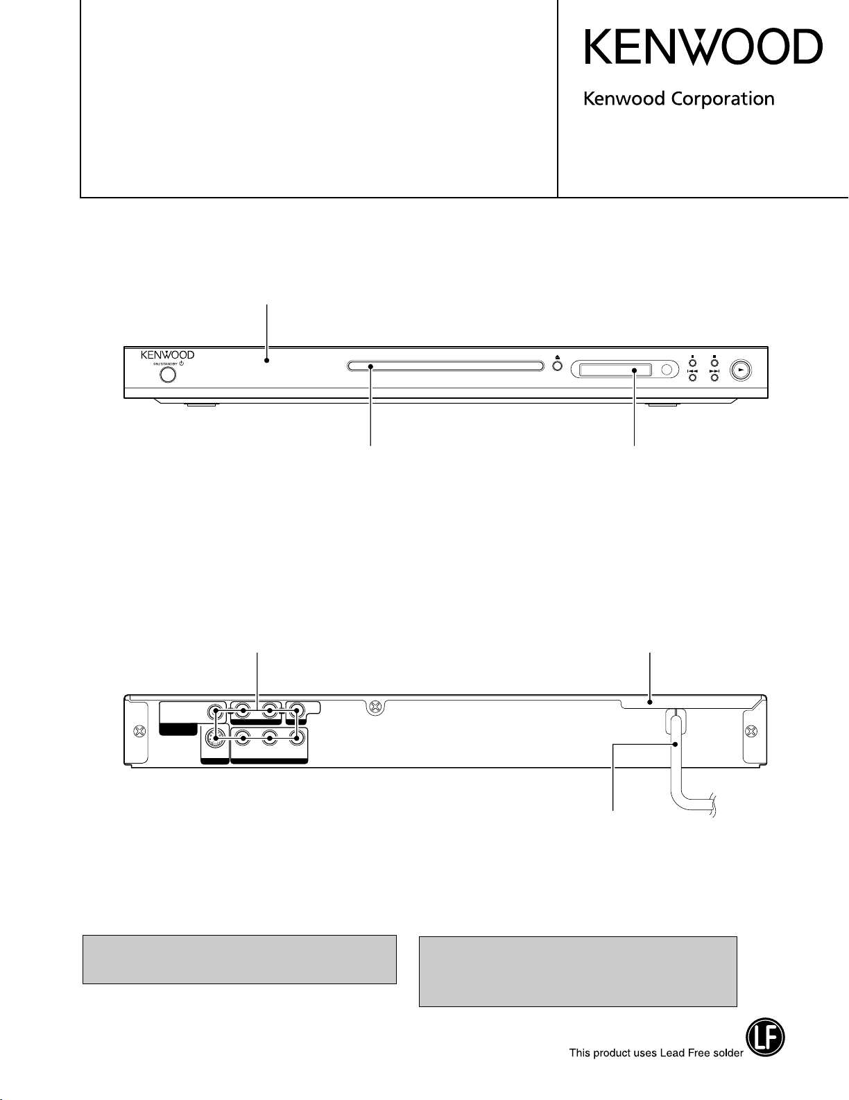
DVD/VCD/CD PLAYER
.
OUT
OUT
OUTOUT
YC
B CR
COMPONENT VIDEO
AUDIO
VIDEO
R
L
DIGITAL OUT
(PCM/BIT STREAM)
COAXIAL
S VIDEO
DVF-3200-S/3250-B
DVF-3250-S
SERVICE MANUAL
Panel ass’y*
(A60-)
Door *
(A29-)
© 2005-3 PRINTED IN KOREA
B51-5944-00 (K/K) 1010
Window, deco
(B11-1620-08)
Jack, RCA *
(E63-)
In compliance with Federal Regulations, following are reproduction of labels on, or inside the product relating to laser
product safety.
Case *
(A09-)
AC cord *
(E30-)
* Refer to parts list on page 14.
KENWOOD Corp. certifies this equipment conforms to DHHS
Regulations No.21 CFR 1040. 10, Chapter 1, subchapter J.
DANGER : Laser radiation when open and interlock defeated.
AVOID DIRECT EXPOSURE TO BEAM.
DVF-3200
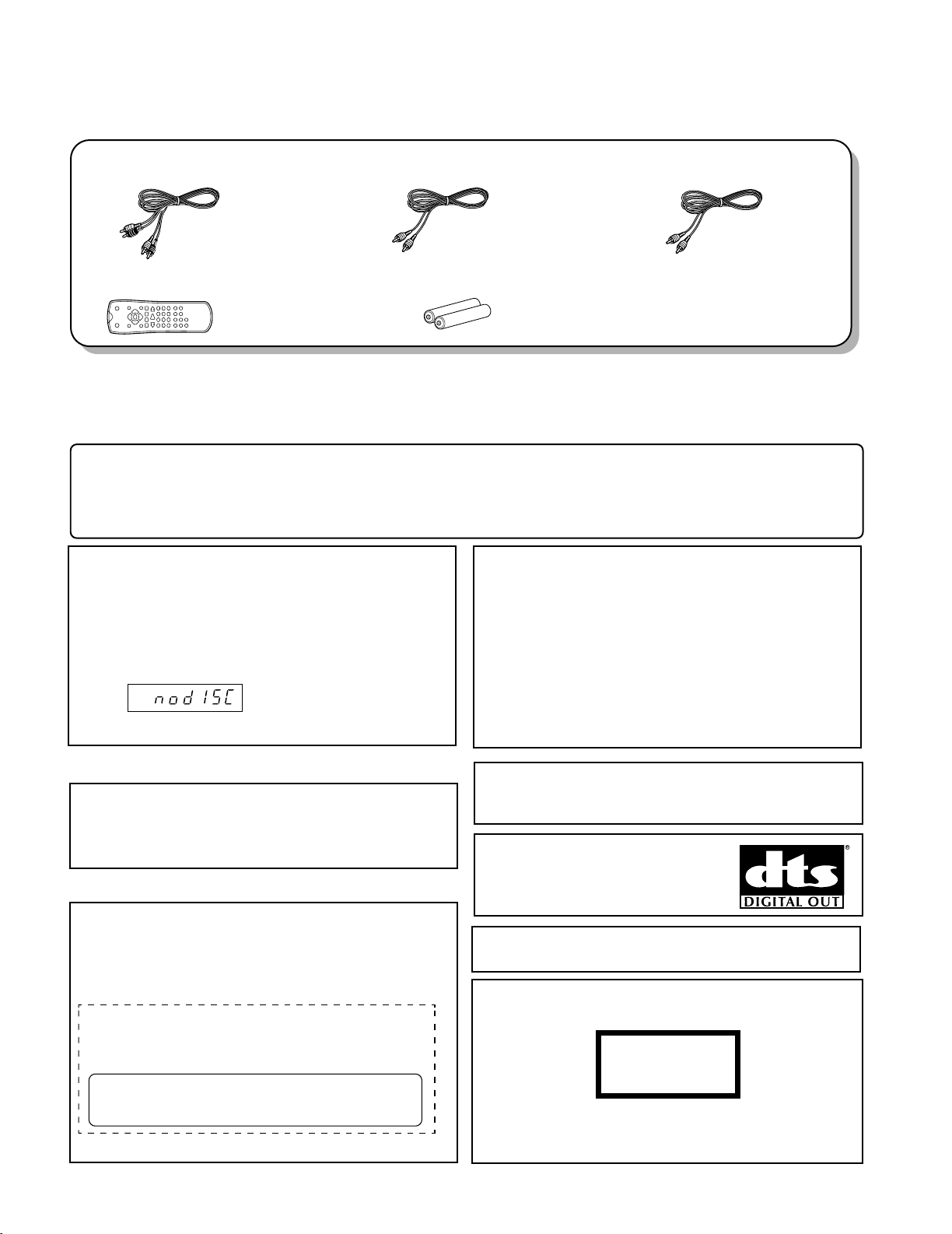
Audio cord (Red, White) ...(1)
(E30-0505-05)
Batteries (R03/"AAA" -size) ...(2)Remote control unit ...(1)
(A70-1660-08)
Video cable(Yellow) ...(1)
(E30-7318-05)
Coaxial cable (Black) ...(1)
(E30-7317-05)
The marking of products using lasers
(For countries other than U.S.A. and U.S.-Military)
The marking this product has been classified as Class 1. It
means that there is no danger of hazardous radiation outside
the product.
Location: Back panel
CLASS 1
LASER PRODUCT
CAUTION:
Use of controls or adjustments or performance of procedures
other than those specified herein may result in hazardous radiation exposure.
In compliance with Federal Regulations, the following are reproductions of labels on, or inside the product relating to laser product safety.
KENWOOD CORPORATION
2967-3, ISHIKAWA-CHO,
HACHIOJI-SHI,
TOKYO, JAPAN
KENWOOD CORP. CERTIFIES THIS EQUIPMENT
CONFORMS TO DHHS REGULATIONS NO. 21 CFR
1040.10, CHAPTER 1, SUBCHAPTER J.
Location: Back Panel
For the U.S.A.
Screen saver
The screen saver appears when you leave the DVD
player in stop mode for about 5 minutes.
If the Screen saver is displayed for 5 minutes, the
DVD player automatically turns itself off.
Caution on condensation
Before transporting or moving this unit, carry out the
following operations.
1. Set the POWER ON/OFF switch to the ON
without loading a disc.
2. Wait a few seconds and verify that the display
shown appears.
(no disc)
3. Set the POWER ON/OFF switch to OFF.
Note related to transportation and movement
Condensation (of dew) may occur inside the unit when there is a great
difference in temperature between this unit and the outside. This unit
may not function properly if condensation occurs. In this case, leave
the unit for a few hours and restart the operation after the condensation has dried up.
Be specially cautious against condensation in the following circum-
stances:
When this unit is carried from one place to another across a large
difference in temperature, when the humidity in the room where
this unit is installed increases, etc.
Operation to reset
The microprocessor may fall into malfunction (impossibility to operate erroneous display, etc.) when the power
cord is unplugged while power is ON or due to an external factor.
In this case, switch off the power, wait for several seconds, and then switch the power on again.
"DTS" and "DTS Digital Out" are registered trademarks of Digital Theater
Systems, Inc.
Manufactured under license from Dolby Laboratories.
"Dolby" and the double-D symbol are trademarks of Dolby
Laboratories.
DivX, DivX Certified, and associated logos are trademarks
of DivXNetworks, Inc. and are used under license.
ACCESSORIES / CAUTIONS
ACCESSORIES
CAUTIONS
2
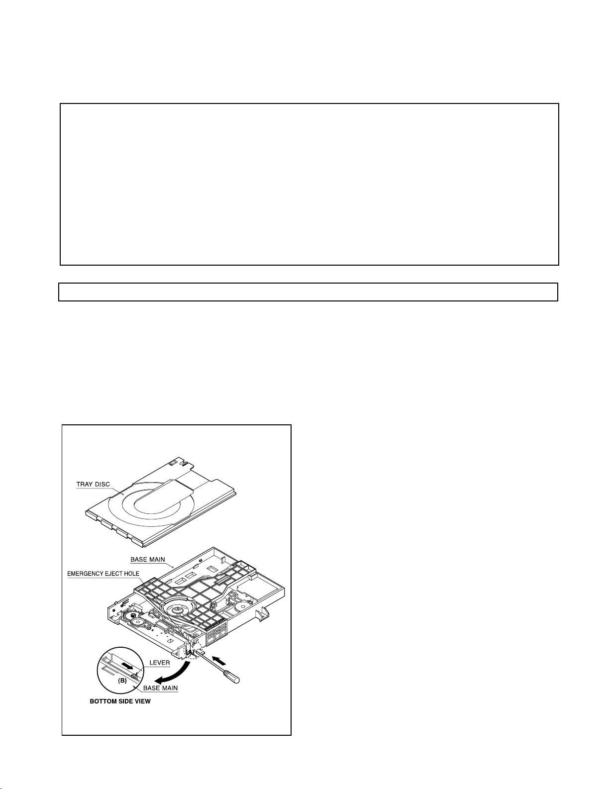
1) Insert and push a Driver in the emergency eject
hole(A) at the right side, or put the Driver on the
Lever(B) of the Gear Emergency and pull the Lever(B)
in direction of arrow so that the Tray Disc is ejected
about 15~20mm.
2) Pull the Tray Disc until it is separated from the Base
Main completely.
Fig.
CAUTIONS
FCC WARNING
This equipment may generate or use radio frequency energy. Changes or modifications to this equipment may cause harmful interfe rence unless the
modifications are expressly approved in the instruction manual. The user could lose the authority to operate this equipment if an unauthorized change
or modification is made.
NOTE:
This equipment has been tested and found to comply with the limits for a Class B digital device, pursuant to Part 15 of the FCC Rules. These limits
are designed to provide reasonable protection against harmful interference in a residential installation. This equipment may cause harmful interference to radio communications, if it is not installed and used in accordance with the instructions. However, there is no guar antee that interference will not occur in a particular installation. If this equipment does cause harmful interference to radio or television rece ption, which can be
determined by turning the equipment off and on, the user is encouraged to try to correct the interference by one or more of the following measures:
— — Reorient or relocate the receiving antenna.
— — Increase the separation between the equipment and receiver.
— — Connect the equipment into an outlet on a circuit different from that to which the receiver is connected.
— — Consult the dealer or an experienced radio / TV technician for help.
For the U.S.A.
For Canada
NOTICE: This Class B digital apparatus complies with Canadian ICES-003.
DVF-3200
CAUTIONS / DISASSEMBLY FOR REPAIR
DISASSEMBLY FOR REPAIR
How to Reset Parental Lock.
1. Connect the TV set to DVF-3200 or 3250.
2. Push the power switch of DVF-3200 or 3250 to be on.
3. Check the display of DVF-3200 or 3250 shown “NO DISC”.
4. Push the “SETUP” key of remote control and TV has “set up
menu”
5. Select the “16:9” on TV.
6. Push #key 1 3 9 7 1 3 9 and ENTER.
Push #key again if mistype.
7. Push the power switch of DVF-3200 or 3250 to be off.
3
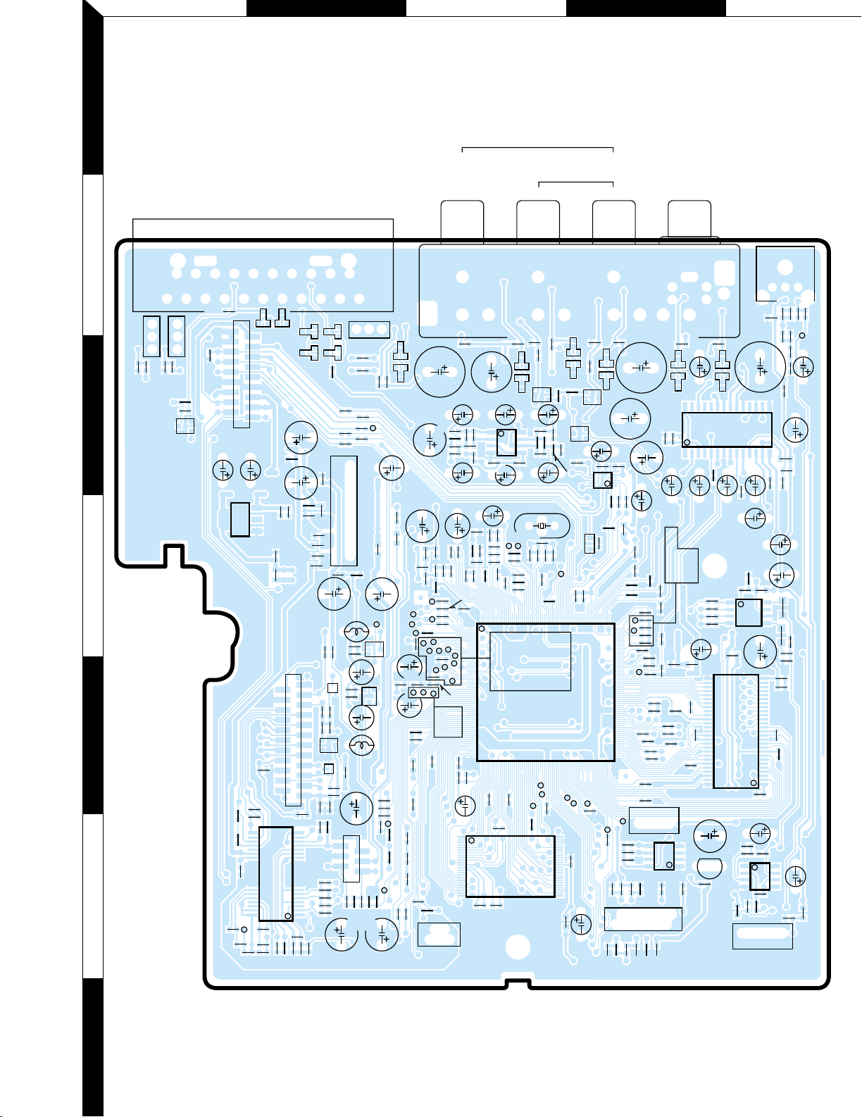
A BDCE
IC901
TIMER (SIDE A)
TIMER (SIDE B)
KEY
RC901
SW901
LED901
CN903
SW902
SW904
SW905
SW903
SW907
SW906
CN902
DIG901
CN901
Q901
C901
C902
POWER
13
STOP
REW
FF
PAUSE
PLAY
OPEN/CLOSE
R901
111
212
13
1
31
116
16
3217
C908
C903
R902
R903
C904
C909
C905
C906
R905
R904
R907
L901
R910
R909
R908
C907
R906
EB
PC BOARD
1
2
3
4
5
6
7
4
Refer to the schematic diagram for the value of resistors and capacitors.
ZD6A3
ZD6A4
ZD605
F6A3
ZD606
JK6A1
OUT L
AUDIO OUT
R
CR CB
COMPONENT VIDEO
Y
COAXIAL
VIDEO DIGITAL OUT
AV
MAIN (SIDE A)
JK601
ZD609
CN602
Q6A1
IC506
Q600
IC601
CN502
ZD603
ZD610
ZD607
ZD608
ZD611
ZD612
Q603
IC602
IC604
JK602
Q206
CN201
IC201
CN202
Q207
Q604
Q201
IC503
IC505
CN503
IC512
IC509
IC508
IC502
CN203
CN501
CN505
Q202
IC501
Q205
ZD604
ZD601
ZD602
ZD6A1
ZD6A2
ZD6A5
ZD6A6
R6A7
R6A5
R6A8
R6A6
C596
C597
L503
R233
R219
C5B4
IGO
L512
R650
R668
R627
C6W4
R6W4
R6W2
R6W3
R662
C633
R646
R647
R603
C604
R601
R645
R604
R602
L601
C610
C624
R616
C614
C635
C630
R661
C634
C629
TP594
TP595
C628
C6W6
TP5A6
R6W1
C6W1
C6W3
C6W5
R6W5
R608
C611
R525
R236
L208
L504
C5B7
C594
R523
R524
C593
F600
C552
R533
C543
R644
R643
R640
C5K3
R5K4
R527
C569
C575
C570
C565
C564
C561
C555
C554
C506
R209
R238
R511
TP558
TP556
TP557
C218
C203
R216
C232
C226R262
R232
R244
R261
TP555
C229
C219
R223
C221
C228
R263
R212
C230
C511 R501 R502
R213
R210
C236
C217
R505
R504
L505
C5C1
C599
R553
R550
C537
C536
C535
C577
R530
C522
C521
C520
C5A6
R510
C519
C515
L501
R503
C518
R571
TP571
TP573
R521
TP577
R586
R641
C581
C583
C585
C598
R562
R551
C595
C534
C587
R519
L5K2
C5K8
R5K9
C5K6
L5K3
R208
C568
C567
TP5A7
TP5A8
C563
R526
L206
C560
C558
R621
R6A4
R6A9
C5B6
R6A3
R6A1
C5B3
C5B8
C5B5
R518
C562
C573
C516
C556
R566
TP5A4
C549
C557
C553
C606
C541
C540
C572
C571
C559
C5B2
L690
C5B1
R659
TP5C1
C202
TP550
TP534
TP536
TP537
R660
C651
R657
R666
R667
R624
R607
R613
R605
R612
C609
C623
R619
R622
C603
C5A1
C618
C601
R609
R615
R620
C620
C621
R606
C639
C619
R532
C582
C584
C612
C607
C5A7
C643
C642
C632
C631
C5K7
C5A8
X501
R623
R669
R649
R648
R663
L602
C6W2
R656
R655
R6A2
1
1
2
21
20
1
10
22
23
2
1
1
1
31
24
48
1
8
5
1
4
41
54
28
1
4
1
1
1
148
5
5
10
6
14
28 15
5
192
129
1
256 193
65 128
64
8
27
15
1
4
8
5
11
212
25
6
2
5
1
15
42
14
28
15
2
17
18
R665
R664
R658
L204
C201
TP535
C204
C505
C501
TP533
C574
C502
C503
C504
C576
C509
C507
TP553
TP551
TP552
TP544
TP543
TP542
TP541
TP540
TP539
TP538
C508
C510
C5A5
C207
R565
R585
L202
R206
L207
R507
R225
R226
R231
C517
C512
R227
R222
R581
TP560
TP559
R582
R569
R528
C523
TP570
TP569
TP568
TP564
TP565
TP563
R529
C231
R214
R215
C524
C578
C525
C580
R517
R516
R514
C586
C589
C5C3
L509
L5K1
C5K5
R5K5
C5K4
R5K7
R5K6
R520
L502
C5A2
C5K1
R5K1
R5K2
R5K3
R580
C591
R522
C532
C533
C531
C530
C5D1
C529
C528
C527
R515
C526
R512
R513
C5K9
R5F3
R5F1
R5F2
R559
R558
C579
R5K8
C513
C514
R509
R243
C233
R211
C220
R260
C227
C235
R202
R235
R201
C205
R639
F6A2
F6A1
BE
BE
BE
GSD
GSD
BE
BE
BE
BE
C641
R626
C640
C644
C650
L205
C5B9
C605
C5A9
C5B0
C636
C5K2
R234
C206
C5A4
C5C2
R205
C622
L201
C588
FHJGI
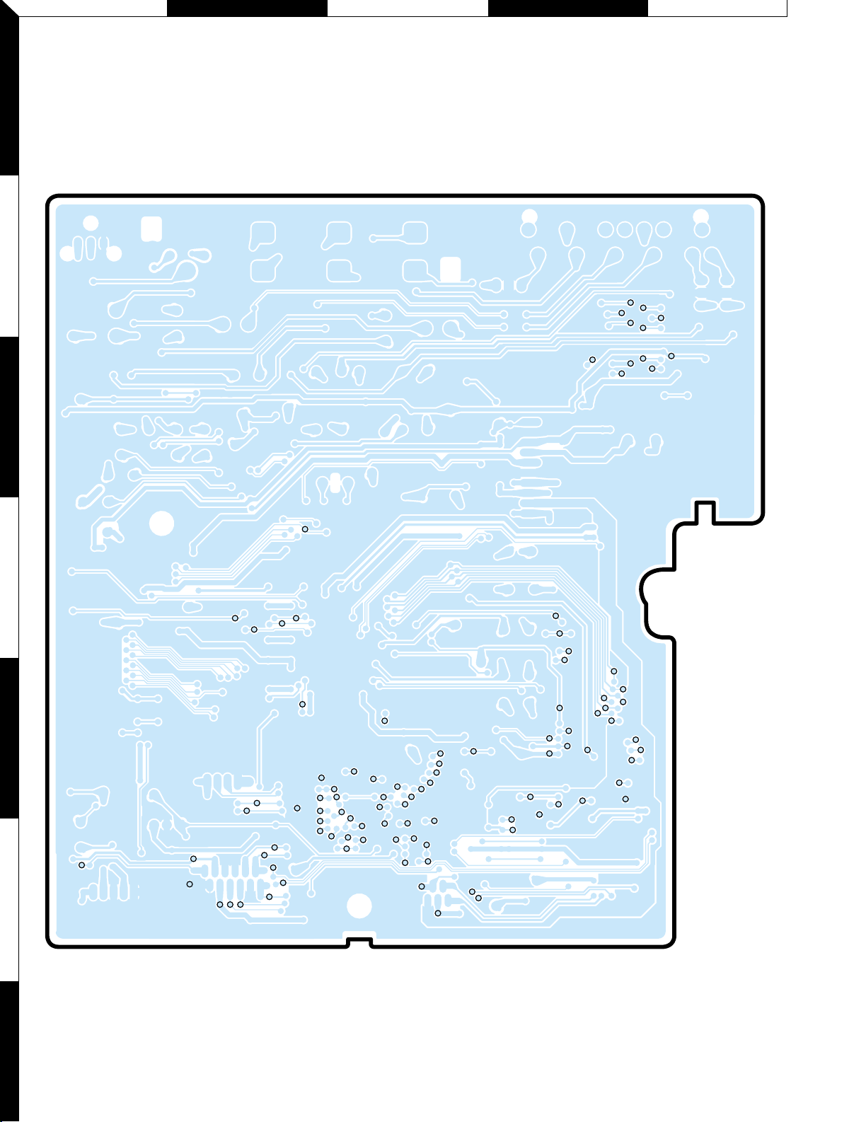
PC BOARD
1
2
3
4
5
6
7
Refer to the schematic diagram for the value of resistors and capacitors.
5
K LNMO
MAIN (SIDE B)
JIG604
JIG605
JIG607
JIG609
JIG608
JIG606
JIG615
JIG613
JIG617
JIG618
TP5A5
TP583
TP578
TP582
TP584
TP574
JIG540
JIG539
JIG541
JIG538
JIG537
JIG536
JIG533
TP521
TP517
TP519
JIG224
JIG226
JIG227
JIG229
JIG228
JIG225
JIG234
JIG217
JIG218
JIG203
JIG202
JIG208
JIG209
JIG210
JIG211
JIG212
JIG213
JIG205
JIG207
JIG222
JIG223
JIG221
JIG219
JIG214
JIG204
JIG201
JIG216
JIG215
JIG233
JIG232
JIG230
JIG231
TP518
TP515
TP509
TP561
TP514
TP513
TP512
TP511
TP501
TP503
TP505
TP502
TP506
TP507
TP528
TP530
TP5A9
TP510
TP508
TP516
TP520
TP523
TP524
TP522
TP525
TP526
TP527
TP529
TP531
TP532
TP5B8
TP5B7
JIG206
TP5C2
TP5C4
JIG534
JIG535
TP5B9
TP5C3
TP504
JIG616
JIG610
PC BOARD
1
2
3
4
5
6
7
6
Refer to the schematic diagram for the value of resistors and capacitors.
 Loading...