

Kenwood DVF-3080-S Service manual
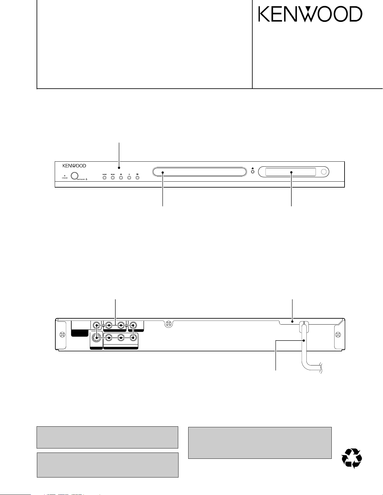
DVD/VCD/CD PLAYER
70%70%
POWRE
OUT
OUT
OUTOUT
YC
B CR
COMPONENT VIDEO
AUDIO VIDEO
R
L
DIGITAL OUT
(PCM/BIT STREAM)
COAXIAL
S VIDEO
DVF-3080-S/8100
SERVICE MANUAL
© 2004-7 PRINTED IN KOREA
B51-5894-00 (K/K) PDF
Panel *
(A60-)
Jack, RCA *
(E63-)
Tray panel *
(A29)
Front glass
(B03-3945-08)
Case
(A01-3925-08)
Power cord *
(E30-)
In compliance with Federal Regulations, following are reproduction of labels on, or inside the product relating to laser
product safety.
Caution : No connection of ground line if disassemble
the unit. Please connect the ground line on
rear panel, PCBs, Chassis and some others.
* Refer to parts list on page 31.
KENWOOD Corp. certifies this equipment conforms to DHHS
Regulations No.21 CFR 1040. 10, Chapter 1, subchapter J.
DANGER : Laser radiation when open and interlock defeated.
AVOID DIRECT EXPOSURE TO BEAM.
DVF-3080-S/8100
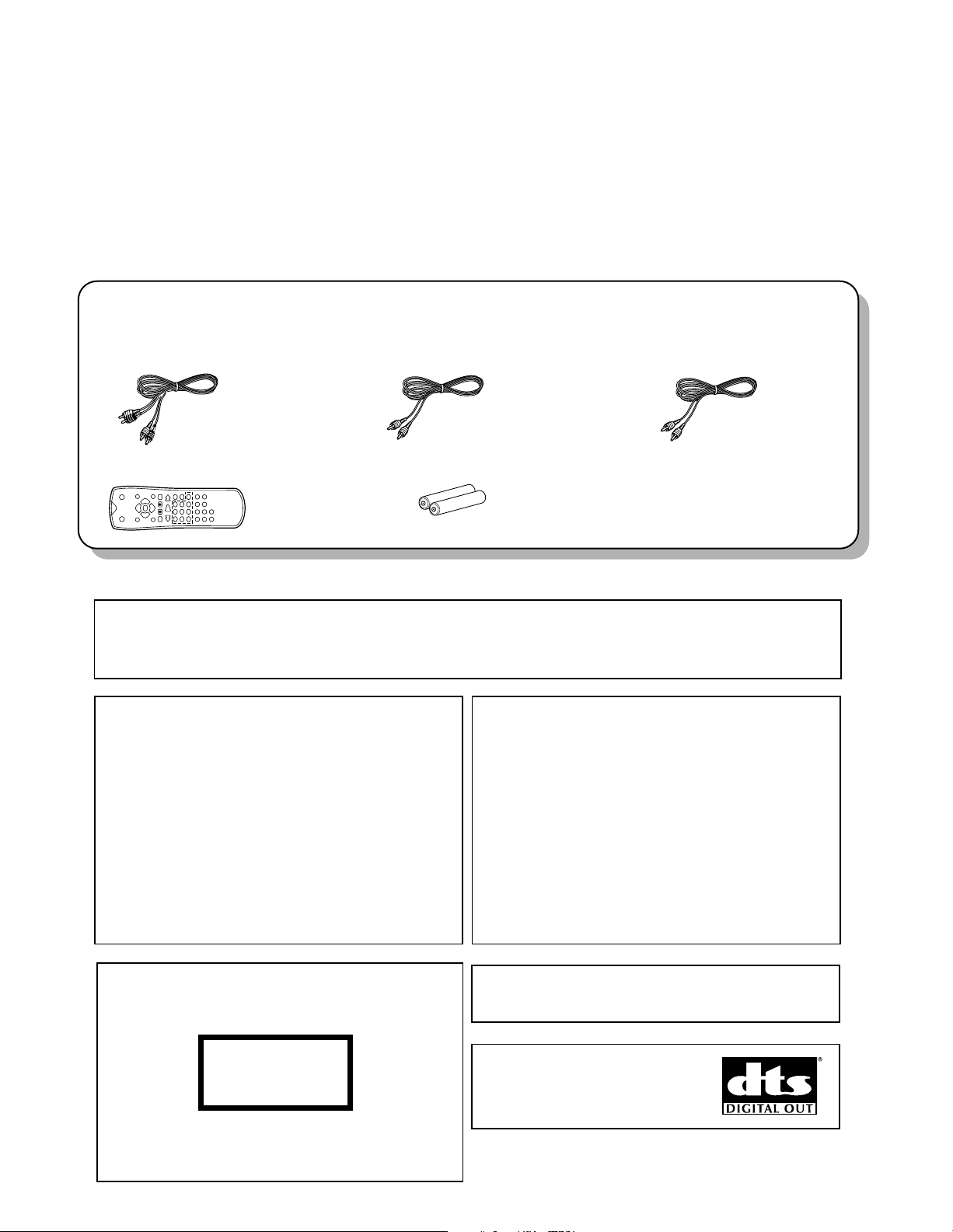
Please confirm that the following accessories are present.
Audio cord (Red, White) ...(1)
(E30-7334-08) : K,P,Y
(E30-7335-08) : E,X
Batteries (R03/"AAA" -size) ...(2)Remote control unit ...(1)
(A70-1660-08)
Video cable(Yellow) ...(1)
(E30-7332-08) : K,P,Y
(E30-7333-08) : E,X
Coaxial cable (Black) ...(1)
(E30-7336-08) : E,X
(E30-7337-08) : K,P,Y
The marking of products using lasers
(For countries other than U.S.A. and U.S.-Military)
The marking this product has been classified as Class 1. It
means that there is no danger of hazardous radiation outside
the product.
Location: Back panel
CLASS 1
LASER PRODUCT
Caution on condensation
Before transporting or moving this unit, carry out the
following operations.
1. Set the POWER ON/OFF switch to the ON
without loading a disc.
2. Wait a few seconds and verify that the display
shown appears.
"NO DISC"
3. Set the POWER ON/OFF switch to OFF.
Note related to transportation and movement
Condensation (of dew) may occur inside the unit when there is a great
difference in temperature between this unit and the outside. This unit
may not function properly if condensation occurs. In this case, leave
the unit for a few hours and restart the operation after the condensa-
tion has dried up.
Be specially cautious against condensation in the following circumstances:
When this unit is carried from one place to another across a large
difference in temperature, when the humidity in the room where
this unit is installed increases, etc.
"DTS" and "DTS Digital Out" are registered trademarks of Digital Theater
Systems, Inc.
Manufactured under license from Dolby Laboratories.
"Dolby" and the double-D symbol are trademarks of Dolby
Laboratories.
The microprocessor may fall into malfunction (impossibility to operate erroneous display, etc.) when the power cord is
unplugged while power is ON or due to an external factor.
In this case, switch off the power, wait for several seconds, and then switch the power on again.
Operation to reset
CONTENTS / ACCESSORIES / CAUTIONS
CONTENTS
CONTENTS / ACCESSORIES / CAUTIONS...............2
DISASSEMBLY FOR REPAIR.....................................3
BLOCK DIAGRAM .......................................................4
DECK MECHANISM ....................................................7
ELECTRICAL TROUBLESHOOTING GUIDE ...........11
WAVEFORMS............................................................15
ACCESSORIES
PC BOARD ................................................................19
CIRCUIT VOLTAGE CHART .....................................21
SCHEMATIC DIAGRAM ............................................23
EXPLODED VIEW .....................................................30
PARTS LIST...............................................................31
SPECIFICATIONS..................................BACK COVER
CAUTIONS
2
DVF-3080-S/8100
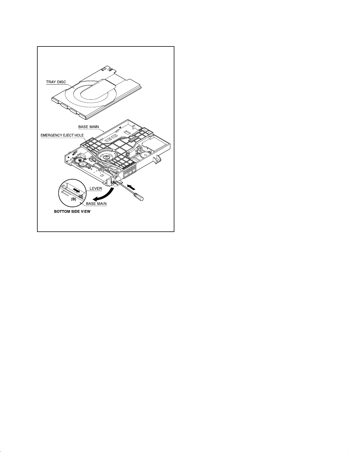
1) Insert and push a Driver in the emergency eject
hole(A) at the right side, or put the Driver on the
Lever(B) of the Gear Emergency and pull the Lever(B)
in direction of arrow so that the Tray Disc is ejected
about 15~20mm.
2) Pull the Tray Disc until it is separated from the Base
Main completely.
Fig.
DISASSEMBLY FOR REPAIR
How to Reset Parental Lock.
1. Connect the TV set to DVF-3080.
2. Push the power switch of DVF-3080 to be on.
3. Check the display of DVF-3080 shown “NO DISC”.
4. Push the “SETUP” key of remote control and TV has “set up menu”
5. Select the “16:9” on TV.
6. Push #key 1 3 9 7 1 3 9 and ENTER.
Push #key again if mistype.
7. Push the power switch of DVF-3080 to be off.
3
4
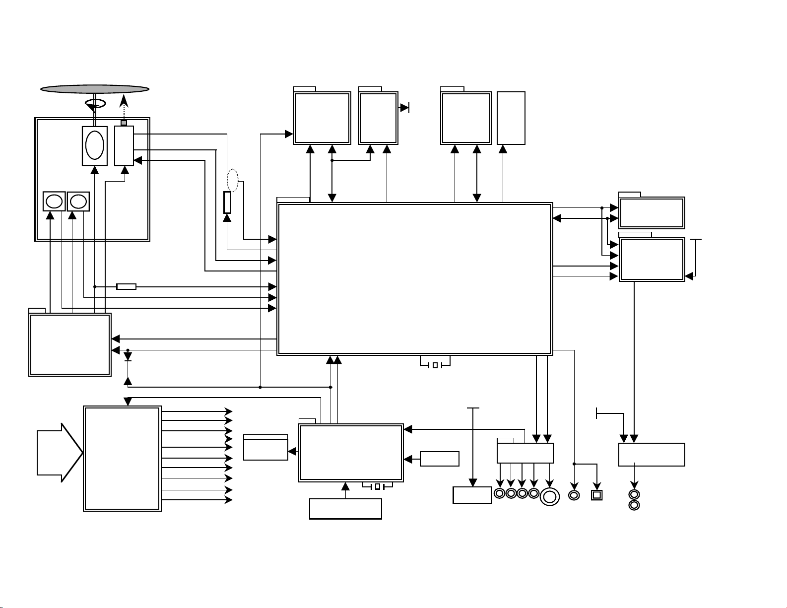
M
M
DISC
SPINDLE
MOTOR
LOADING
MOTOR
DVD : A,B,C,D,RF0
CD : A,B,C,D,E,F,RF0
CDMDI,DVDMDI
PICK
UP
KEY Input
6MHz
B/Pb
IC502
KV802....
KV852....
1M
8BIT
FLASH ROM
M-RESET
ROMAD[0:19]
ROMRD
ROMWR
MD[00:15]
L/R
CVBS
R/Pr
G/Y
TV_DAC[0:3]
Y
C
VF+
AC 90V~240V
50HZ/60Hz
VF-
-27VA
5V
VD33,VD33D
12V
27MHz
PWRCTL
1.8V
IC504
AT24C02A
EEPROM
IC602
OP-AMP
RC901
R/C
LOAD[+,-]
FOCUS[+,-]
TRACK[+,-]
SPINDLE[+,-]
SLED
(FEEDING)
MOTOR
SLED[+,-]
M
VD33D
VD33D
VD18/VD33
VD33D/5V
BCLK
LRCLK
DACCLK
IC604
MM1623XFBE
VIDEO BUFFER
IECDAOUT
COAXIAL
SPDI
D2_T[1:3]
SCART_16:9
RGB_SEL
3V3M
CDLD,DVDLD,SVREF21
5V/8V
HOMESW
INSW,OUTSW
ROMDATA[0:7]
5.2VA
IC901
GMS81C2012(Hynix)
Front Micom
POWER
BOARD
VFD_RXD
S_REQ
5.2VA
8V
DMUTE
IIC/VFD/DAC_SCK
IC503
1M
16BIT
4Bank
SDRAM
VD33D
IIC/VFD/DAC_TXD
+12V
5V
YC_MIX
VIDEO_SW
SER3,DAC_ML0
OPEN,CLOSE,SLEGP,SPINDLE,FOCUS,TRACK,SVREF
IC506
74LCX373
VD33D
GPOPALE
DAC_RST
DMUTE
D2_T[1:3]
SCART_16:9
RGB_SEL
DAC_RST
CD_DVD, VR_CD,VR_DVD
CD_DVD_CT
XSFGN,XSFGP
CN505
EJTAG
TRST
TDI
TDO
TMS
TCK
3.3V1
3.3V2
VD18
IC601
CS4391
2DAC
IC201
IP4504
DRVSB
OPU_SEL
JACK
-27VA/VF+/VF-
DIG901
FLD DISPLAY
MA[00:11]
DMCLK
CSJ
BA0
BA1
DQM
WEJ
CASJ
RASJ
IC501
ALi M3355
DVF-3080-S/8100
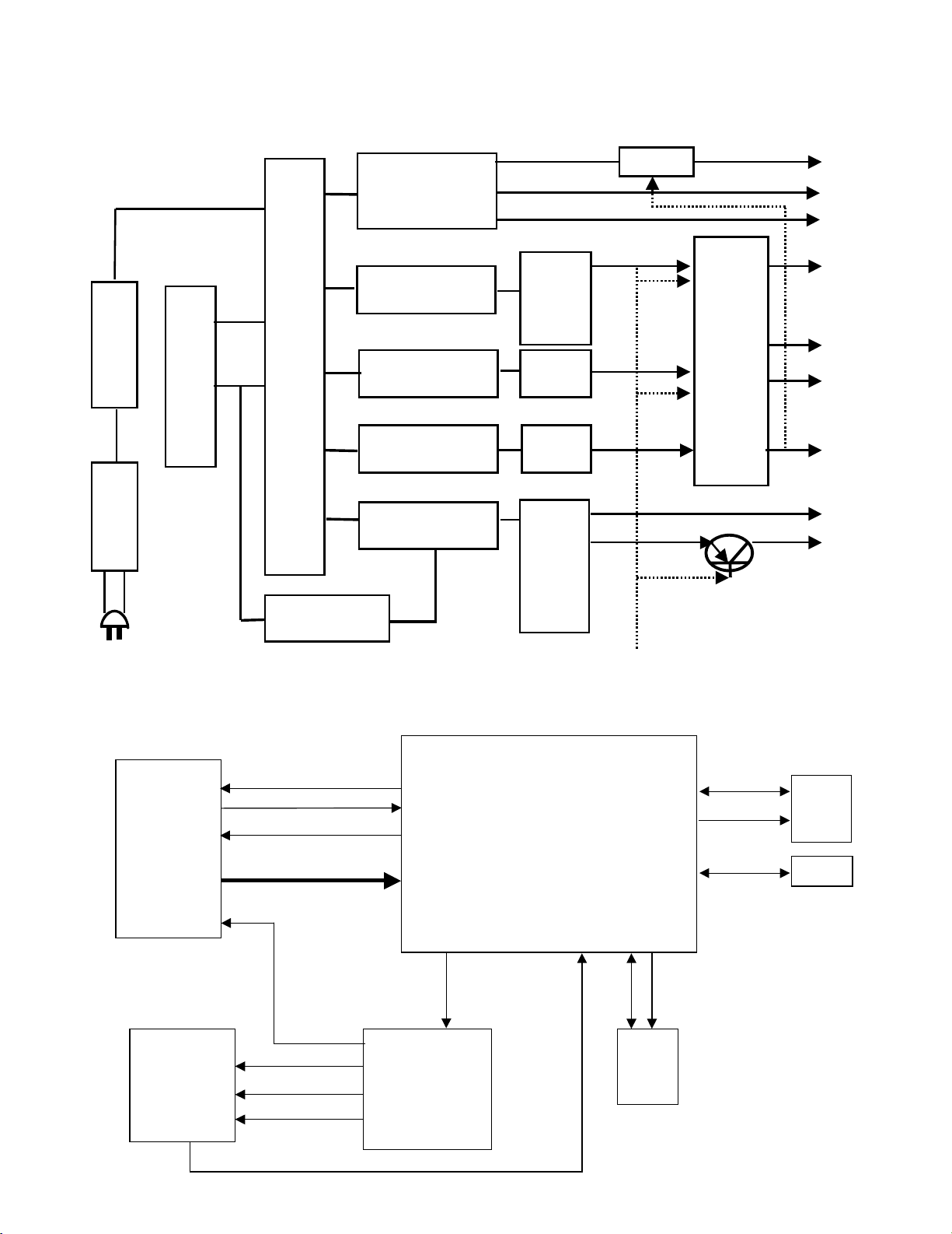
1. Overall Block Diagram
BLOCK DIAGRAM
8VT
5VD
-23VA
VF+
RECTIFIER
LINE FILTER
SWITCHING IC
TRANS
FEED B.
5.2VA
VF-
RECTIFIER(FLD)
RECTIFIER(3.8V)
RECTIFIER(10V)
LPF
LPF
RECTIFIER(14V)
LPF
12V
PWR CTL
MULTI
REG.
1.8V
3.3V
RECTIFIER(5.2V)
LPF
AC100~240V
ON/OFF
PICK
UP
IC501
ALI M3355
DVDPLAYER
COMBO
CHIP
MD
IC201
IP4504
Motor Driver
IC503
64M
SDRAM
FLASH
ROM
EEP
ROM
DVDLD,CDLD,CD_DVD
DVDMDI.CDMDI
SVREF21
DVD:A,B,C,D,RFO
CD:A,B,C,D,E,F,RFO
SLEGP,SPINDLE
FOCUS,TRACK
DRVSB,CLOSE
OPEN,SVREF15
FOCUS+,FOCUSTRACK+,TRACK-
SPINDLE+,SPINDLE-
SLED+,SLED-
LOAD+,LOAD-
OPENSW,CLOSESW,LIMITSW
MA[0:11]
DQM
CLK
CS
CAS
RAS
WE
MD[0:15]
IIC/VFD/DAC_SCK
IIC/VFD/DAC_TXD
ROMAD[0:21]
ROMRD
ROMWR
ROMDATA[0:7]
2. Power(SMPS) Block Diagram
DVF-3080-S/8100
BLOCK DIAGRAM
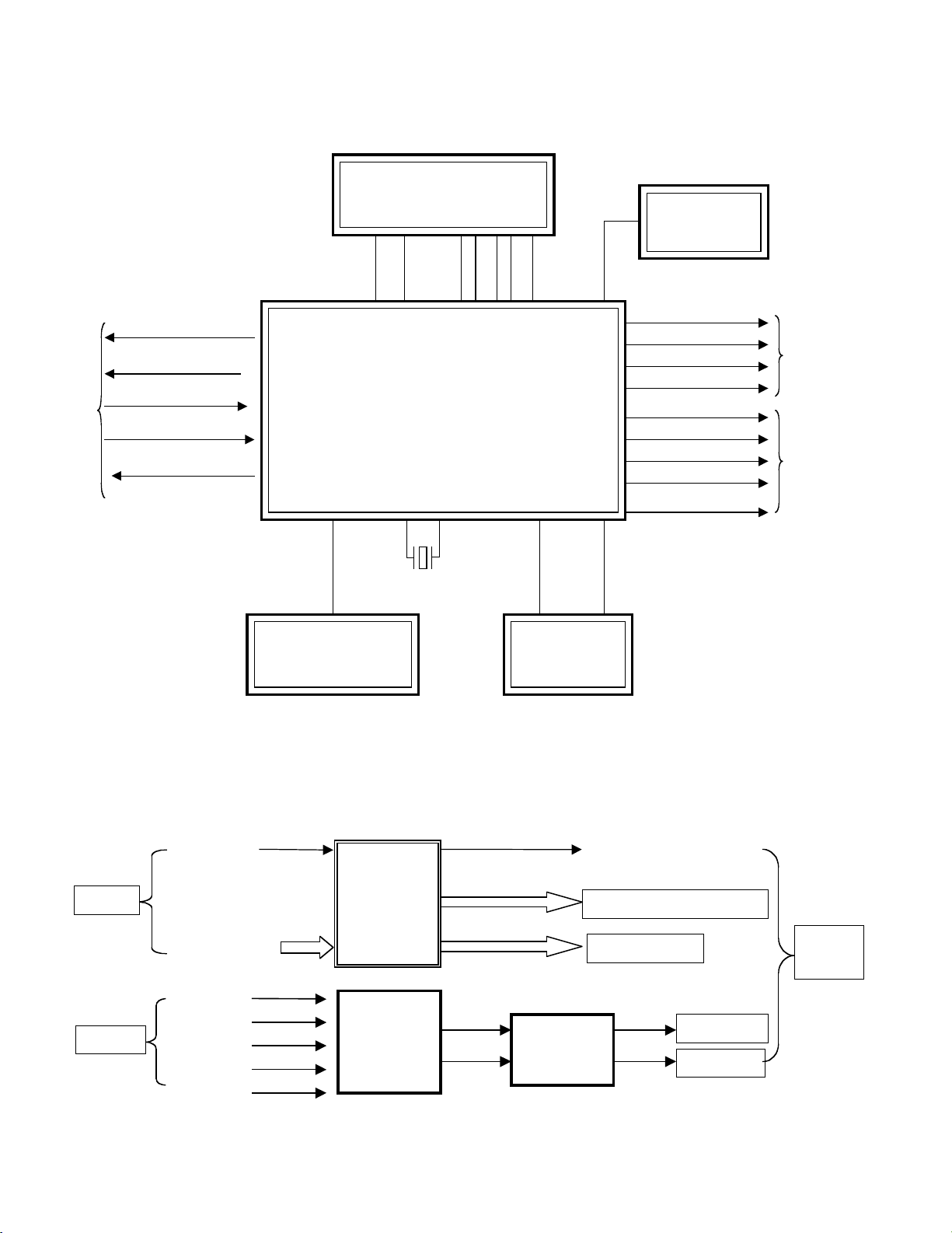
3. SERVO Block Diagram
5
DVF-3080-S/8100
IC501(MPEG+DSP+RF)
ALiM3355
IC503
SDRAM
64M
IC504
EEPROM
FRONT PANNEL
IC502
KV802...
KV852...
CPURST,
ROMWR,
ROMRD
ROMAD(0:19)
TV_DAC0
TV_DAC1
TV_DAC2
TV_DAC3
BCLK,LRCLK,DACCLK
DAC_RST
SER(0:3)
DAC_ML0
VIDEO
Interface
AUDIO
Interface
Pickup
DVD-MD1 , CD-MDI
SVREF21,
DVD:A,B,C,D,RFO
CD:A,B,C,D,E ,F ,RFO
F+, F-, T+, T-, CD_DVD
DVDLD CDLD,
IIC/VFD/DAC_CLK
IIC/VFD/DAC_TXD
MRESET
,S_REQ
VFD_RXD
X501
27MHz
BA1,BA0 ,
CSJ,RASJ,
CASJ,WEJ
,DGM,
DMCLK
MD0:15 ,
MA0:11 ,
MPEG
(RGB)/(YPbPr)
CVBS
COMPONENT(Y.Pb.Pr)
SCART(RGB)
CVBS
IC604
VIDEO 6dB
Amp
IC601
AUDIO DAC
(2CH)
IC602
(OP Amp)
LPF&Buffer
AUDIO 'R'
AUDIO 'L'
MPEG
DAC_RST
DACCLK
BCLK
LRCLK
SER3
A/V
JACK
BLOCK DIAGRAM
4. MPEG & MEMORY Block Diagram
6
5. VIDEO & AUDIO Block Diagram
DVF-3080-S/8100
Starting No.
1
1, 2
1, 2, 3
1, 2, 3, 4
1
1, 6
1, 2, 6
1, 2, 6, 8
1, 2, 6, 8,
9
1, 2, 7
1, 2, 7
1, 2
1, 2 ,13
1, 2, 13, 14
1, 2, 7, 12,
13, 14
1, 2, 13
1, 2, 7, 12,
13, 14, 15,
16, 17
1
2
3
4
5
6
7
8
9
10
11
12
13
14
15
16
17
18
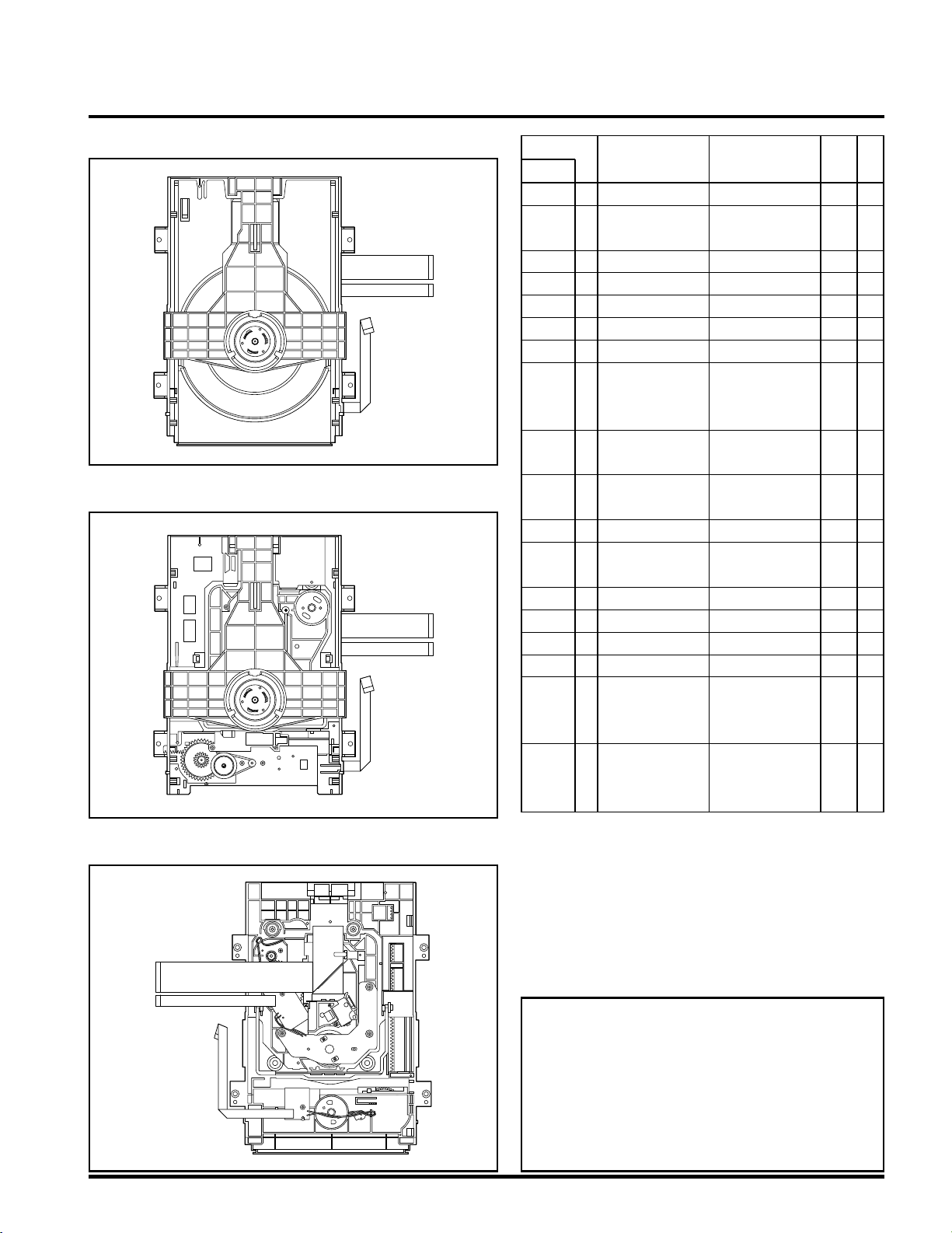
Main Base
Clamp Assembly
Disc
Plate Clamp
Magnet Clamp
Clamp Upper
Tray Disc
Base Assembly Sled
Gear Feed
Gear
Middle
Gear Rack
Rubber Rear
Frame Assembly
Up/Down
Belt Loading
Gear Pulley
Gear Loading
Guide Up/Down
PWB Assembly
Loading
Base Main
4 Screws,
1 Connector
1 Locking Tabs
1 Screw
1 Screw
1 Locking Tab
1 Locking Tab
1 Locking Tab
1 Hook
2Screw
2 Locking Tabs
4-1
4-1
4-1
4-1
4-1
4-2
4-3
4-3
4-3
4-3
4-3
4-4
4-4
4-4
4-4
4-4
4-4
4-4
Bottom
Bottom
Procedure
Parts Fixing Type
Figure
Disass
embly
Note
When reassembling, perform the procedure in
reverse order.
The “Bottom” on Disassembly column of above
Table indicates the part should be disassembled
at the Bottom side.
• Top View (Without Tray)
• Bottom View
• Top View (With Tray)
DECK MECHANISM PARTS LOCATION
7
DVF-3080-S/8100
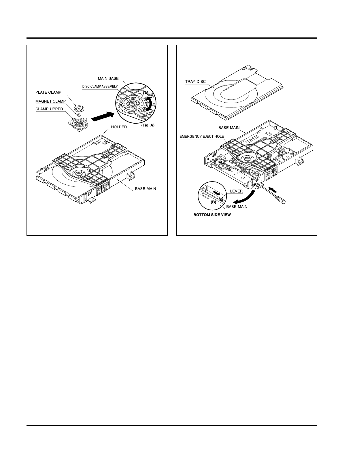
1.Main Base (Fig. 4-1)
1-1. Clamp Assembly Disc
1) Place the Clamp Assembly Disc as Fig. (A)
2) Lift up the Clamp Assembly Disc in direction of
arrow(A).
3) Separate the Clamp Assembly Disc from the Holder
Clamp.
1-1-1. Plate Clamp
1) Turn the Plate Clamp to counterclockwise direction and
then lift up the Plate Clamp.
1-1-2. Magnet Clamp
1-1-3. Clamp Upper
2. Tray Disc (Fig. 4-2)
1) Insert and push a Driver in the emergency eject
hole(A) at the right side, or put the Driver on the
Lever(B) of the Gear Emergency and pull the Lever(B)
in direction of arrow so that the Tray Disc is ejected
about 15~20mm.
2) Pull the Tray Disc until it is separated from the Base
Main completely.
Fig. 4-1 Fig. 4-2
DECK MECHANISM DISASSEMBLY
8
DVF-3080-S/8100
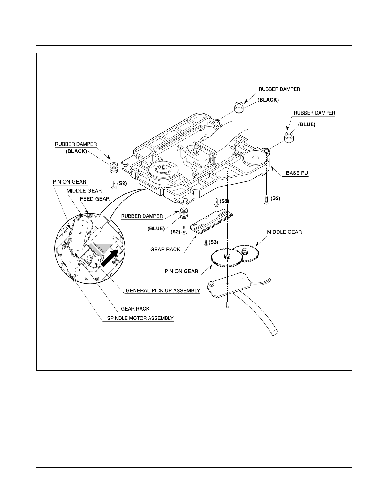
3.Base Assembly Sled (Fig. 4-3)
1) Release 4 Screw(S2).
2) Disconnect the FFC Connector(C1)
3-1. Gear Feed
3-2. Gear Middle
3-3. Gear Rack
1) Release the Scerw(S3)
4. Rubber Rear (Fig. 4-3)
Fig. 4-3
DECK MECHANISM DISASSEMBLY
9
DVF-3080-S/8100
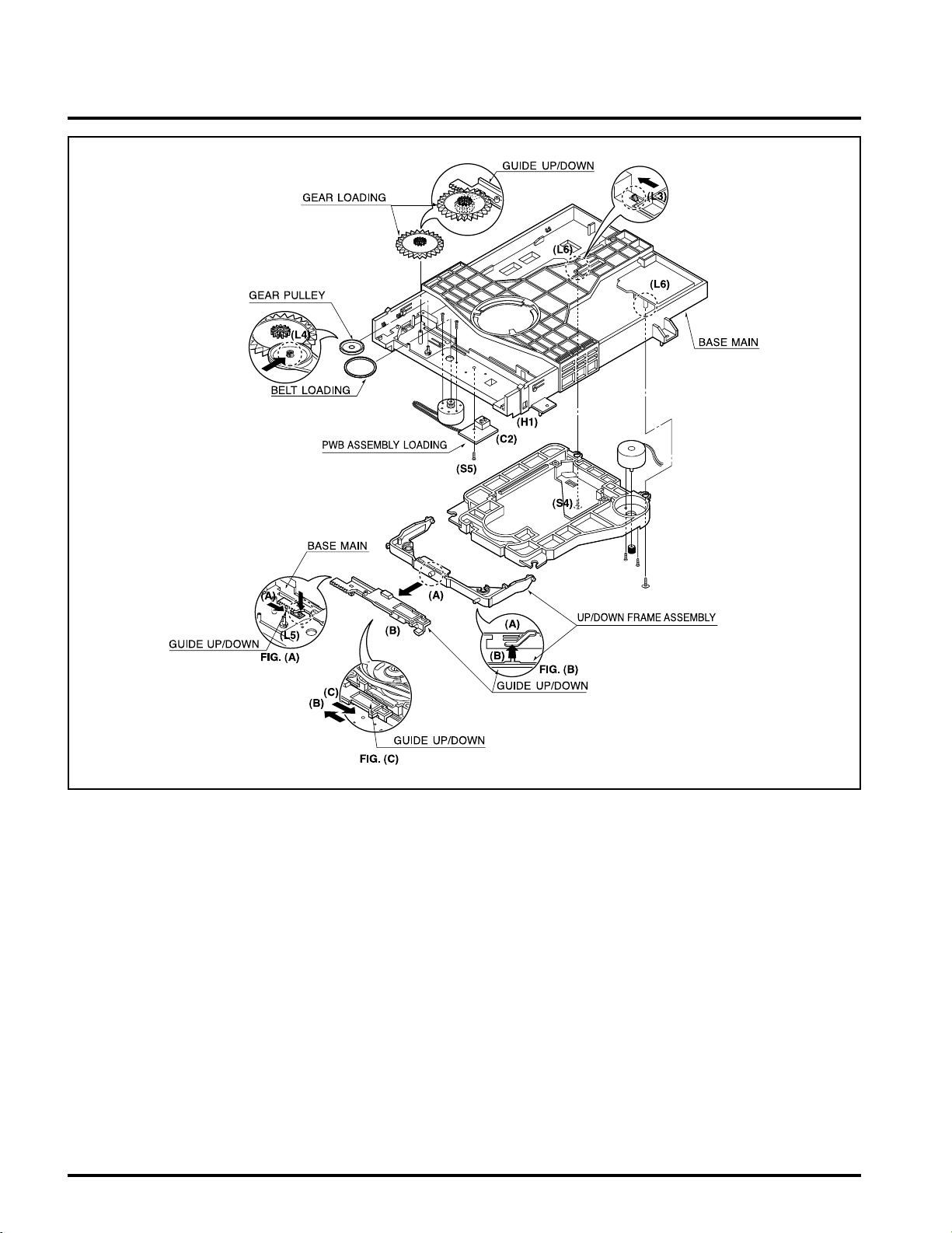
5. Frame Assembly Up/Down (Fig. 4-4)
Put the Base Main face down(Bottom Side)
1) Release the screw(S4)
2) Unlock the Locking Tab(L3) in direction of arrow and
then lift up the Frame Assembly Up/Down to separate
it from the Base Main.
• When reassembling move the Guide Up/Down in direction
of arrow(C) until it is positioned as Fig.(C).
• When reassembling insert (A) portion of the Frame
Assembly Up/Down in the (B) portion of the Guide
Up/Down as Fig.(B)
6. Belt Loading(Fig. 4-4)
Put the Base Main on original position(Top Side)
7. Gear pulley (Fig. 4-4)
1) Unlock the Locking Tab(L4) in direction of arrow(B) and
then separate the Gear Pulley from the Base Main.
8. Gear Loading (Fig. 4-4)
9. Guide Up/Down (Fig. 4-4)
1) Move the Guide Up/Down in direction of arrow(A) as
Fig.(A)
2) Push the Locking Tab(L5) down and then lift up the
Guide Up/Down to separate it from the Base Main.
When reassembling place the Guide Up/Down as Fig.(C)
and move it in direction arrow(B) until it is locked by the
Locking Tab(L5). And confirm the Guide Up/Down as Fig.(A)
10. PWB Assembly Loading (Fig. 4-4)
Put the Base Main face down(Bottom Side)
1) Release 1 Screws(S5)
2) Unlock the Loading Motor (C2) from the Hook (H1) on
the Base Main.
3) Unlock 2 Locking Tabs(L6) and separate the PWB
Assembly Loading from the Base Main.
11. Base Main(Fig. 4-4)
Note
Note
Note
Note
Note
Fig. 4-4
DECK MECHANISM DISASSEMBLY
10
 Loading...