


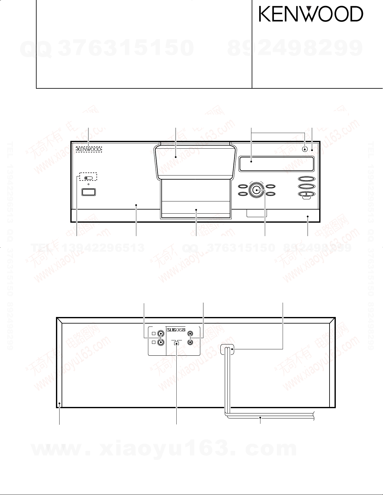
MULTIPLE COMPACT DISC PLAYER
MULTIPLE COMPACT DISC PLAYER
STANDBY
POWER
DISPLAY
DISC SKIP
0
PUSH OPEN
RANDOM
CONFIRM
REPEAT
6
7
4 ¢
200 DISC LOADING WITH TWIN PICK UP MECHANISM
TIMER PLAY
OFF ON
L
R
OUTPUT SYSTEM
CONTROL
SL16 XS8
CD-223M/DPF-J3010
Q
Q
CD-224M/DPF-J5010
3
7
6
3
1
5
1
5
0
SERVICE MANUAL
KENWOOD badge
(B43-0302-04)
TEL 13942296513 QQ 376315150 892498299
Front glass (DOOR) *
(B10-)
9
8
Front glass (FL)
(B10-2396-08)
4
2
© 1998-2/B51-5409-00 (K/K) 3430
9
2
8
Dressing panel *
(A21-)
9
9
TEL 13942296513 QQ 376315150 892498299
TEL
Knob (TIMER REC)
(K29-6885-08)
Dressing panel *
(A21-)
13942296513
Phono jack
(E63-0122-05)
Panel (FRONT, LID)
(A29-0886-18)
Q
Q
Mini phone jack
(E11-0293-05)
3
7
9
Panel *
(A60-)
2
4
9
8
2
Knob (DISC SKIP)
(K29-6824-08)
5
1
5
1
3
6
Illustration is CD-224M/DPF-J5010.
8
0
Power cord bushing
(J42-0083-05)
9
9
Metallic cabinet
(A01-3501-08)
w
w
w
.
xia
Slide switch
(S31-2132-05)
o
y
u
1
6
3
AC power cord *
(E30-)
* Refer to parts list on page 19.
.
c
o
m
CD-223M/224M/DPF-J3010/J5010
REMOTE CONTROL UNIT
RC-P0306
BEST
SELECTION
ABC
2
DEF
3
JKL
5
GHI
4
MNO
6
CONFIRM
1
REPEAT
TUV
8
PRS
7
WXY
9
RANDOM
QZ
0
& ( ) – /
+100
SPACE/
CHECK
CHARACTER/SEARCH
CURSOR
DELETE/
CLEAR
CHARACTER/
P.MODE
' , : ? !
+10
DOWN UP
L R
DISPLAY
MODE
SET
INSERT
ENTER
DISC
SELECTOR
∞ DISC SKIP 5
7 6
4 ¢
1 ¡
POWER
MULTIPLE COMPACT DISC PLAYER
STANDBY
POWER
BEST SELECTION
DISC SKIP
RANDOM
MODE
CONFIRM
REPEAT
DISPLAY/INSERT
6
7
4 ¢
1
¡
P.MODE/CHARA.
ENTER
CHECK/
SPACE
CLEAR/
DELETE
SET
200 DISC LOADING WITH TWIN PICK UP MECHANISM
TIMER PLAY
OFF ON
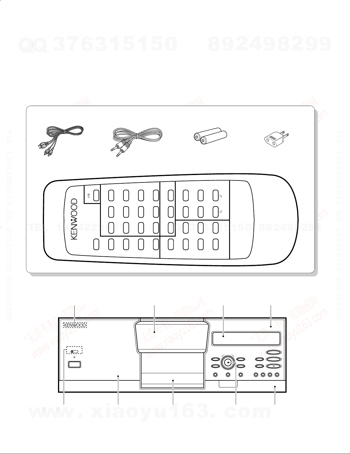
CONTENTS/ACCESSORIES/EXTERNAL VIEW
Contents
Q
Q
CONTENTS/ACCESSORIES/EXTERNAL VIEW.......2
MECHANISM OPERATION DESCRIPTION ..............3
DISASSEMBLY FOR REPAIR....................................4
CIRCUIT DESCRIPTION............................................5
ADJUSTMENT..........................................................10
Accessories
Audio cord (1)
(E30-0505-05)
TEL 13942296513 QQ 376315150 892498299
Remote control unit (1)
(A70-1175-08) : CD-224M/DPF-J5010
3
7
6
1
3
5
System control cord (1)
(E30-2816-05)
1
5
0
PC BOARD ...............................................................11
SCHEMATIC DIAGRAM...........................................13
EXPLODED VIEW ....................................................17
PARTS LIST..............................................................19
SPECIFICATIONS ......................................Back cover
Batteries (R6/AA) (2)
8
4
2
9
Battery cover : (A09-0374-08)
9
AC Plug adaptor (1)
(E03-0115-05) M type only
8
2
9
9
TEL 13942296513 QQ 376315150 892498299
TEL
External view
Knob (TIMER REC)
w
2
(K29-6885-08)
w
13942296513
KENWOOD badge
(B43-0302-04)
w
.
xia
Dressing panel *
(A21-)
o
9
9
2
8
9
4
2
9
8
0
5
1
5
1
3
6
7
3
Q
Q
Front glass (DOOR) *
(B10-)
6
Panel (FRONT, LID)
(A29-0886-18)
y
u
1
Front glass (FL)
(B10-2456-08)
o
Knob (DISC SKIP)
3
.
Illustration is CD-223M/DPF-J3010.
(K29-6824-08)
c
* Refer to parts list on page 19.
m
Dressing panel *
(A21-)
Panel *
(A60-)
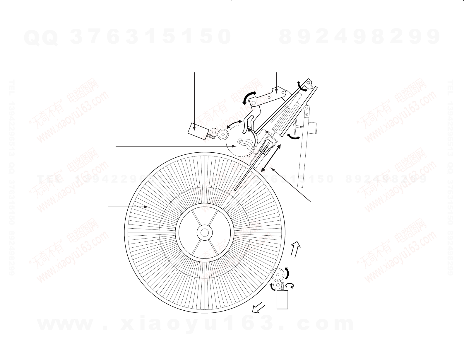
There is the motor
above the big gear.
The pin drawn the dot
line travels with the big
gear to the arm.
The turning direction
of the shortest route
is choosed by the
rotary motor.
<DISC LOADING>
The Holder M(Stocker Rotary)
stops to turn at the choosed
disc number. The turning force
of the loading motor(LM) is to
carry the disc to the holder
and the disc is clamped.
This holder clamps
and loads the disc.
The slider travels by
the turning force of
the big gear. The force
is linked to the holder.
The disc clamp is done
by the arm movement.
Q
Q
3
7
6
3
1
5
1
5
0
8
9
2
4
9
8
2
9
9
TEL 13942296513 QQ 376315150 892498299
TEL
139
4229651
3
3
6
7
Q
Q
3
1
0
5
1
5
8
9
2
4
9
8
2
9
TEL 13942296513 QQ 376315150 892498299
MECHANISM OPERATION DESCRIPTION
9
CD-223M/224M/DPF-J3010/J5010
w
3
w
w
.
x
i
a
o
y
u
1
6
3
.
c
o
m
4
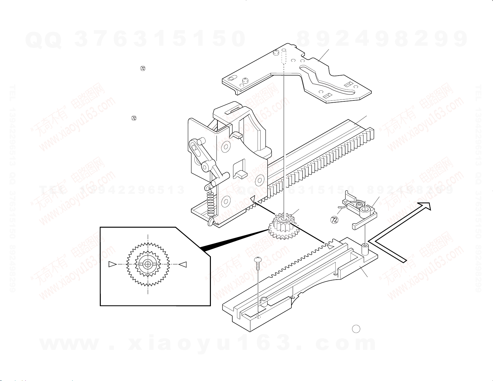
: Ref. No. in exploded view
How to Assemble Mechanism.
1. Remove the lever(ª) with the spring ( ).
2. Slide the actuator assy(1+9) to the
fully frontward.
3. Set the gear(•) to meet with the mark of
its and the actuator assy(1+9).
4. Set the guide(≠) to meet the mark of its
and the gear(•).
5. Load the lever(ª) with the spring ( )
to the guide(≠) after sliding the actuator
assy(1+9) slightly backwards.
1
9
≠
•
ª
CD-223M/224M/DPF-J3010/J5010
Q
TEL 13942296513 QQ 376315150 892498299
Q
TEL
3
7
139
6
4229651
3
1
5
3
1
5
0
Q
Q
3
7
6
8
3
1
9
5
1
2
5
0
4
8
9
9
2
8
4
9
2
8
2
9
9
9
TEL 13942296513 QQ 376315150 892498299
DISASSEMBLY FOR REPAIR
9
w
w
w
.
x
i
a
o
y
u
1
6
3
.
c
o
m

CD-223M/224M/DPF-J3010/J5010
LOAD_P1
UNLOAD_SW1SQCK
75
SQCK
LOADM+1
LOADM-1
LOADM+2
LOADM-2
LOAD_P2
LOAD_M1
SO
SI
DOT/QDATA
72
67
X32, IC14
X32, IC15
LOAD_M2
LOAD_SW2
UNLOAD_SW2
STB1
STB2
74
71
46
63
62
58
59
47
55
56
uPD784215GF509
uPD784214GF501
PERIPHERY IC RESET
JOG
IC RESET
ENCODE_B
ENCODE_A
X32, IC10
X32, IC9
14~21
(D7~D0)
SI
CLK
uPD17215GT
-737
(REMOCON
uCOM)
D0~D7
STB
RxDO
TxDO
RTREN
RWRREQ
RTREN 11
RWRREQ 13
LDC
70
LASER ON/OFF
RWR
RWR 12
MON
RMUTE
31
48
ANALOG MUTE
SPINDLE MOTOR ON/OFF
84~91
(AD0~AD7)
76~83, 92~99
1~2
(A0~A17)
8/16
TYPE53
54
8BIT/16BIT
MODEL DISCRIMINATION
X25, IC3
CS
CE
SERIAL
COMMUNICATION
CD-2280M/DPF-J9010 only
CD-2260M/DPF-J7010 only
CD-2280M/DPF-J9010
CD-2260M/2280M/DPF-J7010/J9010 (M5M5108BFP-70LL)
CD-223M/224M/DPF-J3010/J5010 (HM62256BLFP-8T)
WE
OE
IC2 X32, IC8
S1_SW
CLOCK
34
CDM-31
MECHA
3
4
7
S3_SW
S2_SW
S1_SW
S3_SW
S2_SW
DATA
XLAT
36
35
DATA
XLAT
CLOK
CLK
SO
SI
STB
7P
4P
5P 6P
CXD2587Q
(DSP)
uPD780204
(DOT
DRIVER)
uPD780204
(DOT
DRIVER)
uPD780024
(SUB uCOM)
LED_A
ON/
STANDBY
LED_B
POWER ON
PLAY ON/OFF
DISC SW
D_PWM
ROTARY+
23
10
D_SENS
24
25
28
29
26
27
D_PWM
SCLK
SENS
MUTEG
33
45
32
SCLK
SYSM
SENS
ROTARY-
LOAD SW1
UNLOAD_SW1
LOAD SW1
UNLOAD_SW2
DLE_SW2
ROTALY_CW
ROTALY_CCW
SCOR
SUBQ
73
44
SQSO
SCOR
A1 SW A2 SW
P2
P1
8
5
6
30
RxD1
TxD1
68
69
49
50
SBUSY
SDATA
TxD2
RxD2
66
65
VR-2090 or
VR-2080
ASTB
RD
WR
CS
CIRCUIT DESCRIPTION
7
1. Main microprocessor : uPD784215GF509 (IC8) CD-2260M/2280M/DPF-J7010/J9010
Q
Q
1-1 Microprocessor periphery block diagram
TEL 13942296513 QQ 376315150 892498299
3
6
1
5
1
3
: uPD784214GF501 (IC8) CD-223M/224M/DPF-J3010/J5010
5
0
TEL
13942296513
Q
Q
3
4
2
9
8
3
6
7
0
5
1
5
1
9
2
9
8
8
4
2
9
8
9
2
9
9
TEL 13942296513 QQ 376315150 892498299
9
w
w
w
.
xia
o
y
u
1
6
3
.
c
o
m
5

CD-223M/224M/DPF-J3010/J5010
CIRCUIT DESCRIPTION
7
1-2 Pin description
Q
Q
Pin No. Pin Name I/O Description
TEL 13942296513 QQ 376315150 892498299
TEL
w
* CD-223M/224M/DPF-J3010/J5010
3
1* A16 O No connection.
1 A2 O Address buss of SRAM.
2* A17 O No connection.
2 NC – No connection.
3 S3-SW I Mechanism address detector switch.
4 S2-SW I Mechanism address detector switch.
5 RD O SRAM read strobe.
6 WR O SRAM write strobe
7 S1-SW I Mechanism address detector switch.
8 ASTB O No connection.
9 VDD – Power supply (+5V).
10 +5VPUL O Disc sensor PWM output.
11* RTRN O No connection.
11 RTRN I TX permission data to remote control microprocessor.
12* RWR O No connection.
12 RWR I Reading data of remote control microprocessor.
13* RWRR O No connection.
13 RWRR O TX request data to remote control microprocessor.
14-21* L-D0-D7 O No connection.
14-21 L-D7-D0 O Data output to remote control microprocessor.
22 TEST – GND.
23 DISC-SW I Disc sensor.
13942296513
24 ROTARY-CW O Mechanism rotary motor (+). H : CCW
25 ROTARY-CCW O Mechanism rotary motor (-). H : CW
26 LOADM+1 O Loading motor (+) for main pickup.
27 LOADM-1 O Loading motor (-) for main pickup.
28 LOAD-SW1 I Loading switch for main pickup.
29 UNLOAD-SW1 I Unloading switch for main pickup.
30 CE/CS O Chip selector
31 MON O Control port of poor focus works.
32 SCLK O Sens serial data read clock.
33 SENS I SENS signal input.
34 CLOCK O Serial data clock.
35 XLAT O CXD2587Q latch.
36 DATA O Serial data output.
37 VDD – Power supply (+5V).
38, 39 X1, 2 – Main system clock (12.5MHz).
40 VSS – GND.
41 XT2 – No connection.
42 XT1 I GND.
43 RESET I System reset signal input.
44 SCOR I Sub code synchro detection.
45 MUTEG O Muting control output. H : MUTE ON.
46 STB2 O Strobe signal output to dot driver2 (DPF-J9010 only).
47 IC RESET O IC reset.
48 RMUTE O Analog mute. L : MUTE ON.
w
w
6
.
xia
3
1
5
o
1
y
5
u
0
Q
Q
1
3
6
7
3
6
8
3
.
9
1
1
5
c
2
5
o
4
0
m
9
8
9
8
2
4
2
9
8
9
2
9
9
TEL 13942296513 QQ 376315150 892498299
9
6
CD-223M/224M/DPF-J3010/J5010
CIRCUIT DESCRIPTION
7
Q
Q
TEL 13942296513 QQ 376315150 892498299
%
%
TEL
3
Pin No. Pin Name I/O Description
49 SDATA I/O Serial data signal I/O.
50 SBUSY I/O Serial busy signal I/O.
51 AVDD – Power supply(+5V).
52 AVREF – A/D reference power supply.
53 A/D0 I Model selector.
54 8/16 I 8/16 bit selector. H:16bit.
55 JOG2 I Encoder signal A input.
56 JOG1 I Encoder signal B input.
57 DOOR-SW I Door open/close detector switch.
58 LOAD-SW2 I Load switch2 for sub pickup(DPF-J9010 only).
59 UNLOAD-SW2 I Unload switch2 for sub pickup(DPF-J9010 only).
60 DISC-SW2 I Disc2 sensor(DPF-J7010/J9010 only).
61 VSS – GND.
62 LOADM-2 O Load motor(-) for sub pickup(DPF-J9010 only).
63 LOADM+2 O Load motor(+) for sub pickup(DPF-J9010 only).
64 AVREF1 – D/A reference power supply.
65 RXD2 I UART communication input(DPF-J7010/J9010 only)
66 TXD2 O UART communication output(DPF-J7010/J9010 only)
67 SQCK/SCK-SW O “SQCK,SCK(DOT/DSP clock) selector. L:DSP.”
68 RXD1 I UART communication input(sub u-com)(DPF-J9010 only).
69 TXD1 O UART communication output(sub u-com)(DPF-J9010 only).
70 LDC O Laser on/off.
13942296513
71 STB1 O Strobe signal output to dot driver.
72 S0 I Data input from dot driver.
73 SQS1 I Sub code read data input.
74 S1 O Data output to dot driver.
75 SCK/SQCK O Dot driver/sub code read clock.
76-83* A14-7 O Address output to SRAM.
76-83 A16,14,12,7-3 O Address output to SRAM.
84-91 D0-7 I/O SRAM data buss.
92-99* A1-6,15 O Address output to SRAM.
92-99 A0,1,8-11,13,15 O Address output to SRAM.
100 VSS – GND.
* CD-223M/224M/DPF-J3010/J5010
% I/O port : O (when no used this port)
6
3
1
5
1
5
0
Q
Q
3
7
6
8
3
9
1
5
1
2
5
4
0
9
8
9
8
2
4
2
9
8
9
2
9
9
TEL 13942296513 QQ 376315150 892498299
9
1-3 Key matrix
VOLTAGE KEY PETURN 0 (33) KEY RETURN 1 (32) KEY RETURN 2 (31)
w
w
( ) : IC14 Pin No.
223M/J3010 BEST SEL.
4.166V
3.333V 223M/J3010 CLEAR/DELETE 223M/J3010 SET RANDOM
2.5V 223M/J3010 FB 223M/J3010 ENTER CONFIRM
1.666V 223M/J3010 FF REPEAT
0.833V DOWN PLAY/PAUSE
w
0V UP POWER STOP
223M/J3010 CHECK/SPACE
.
xia
o
y
223M/J3010 MODE
223M/J3010 P.MODE/CHARA
u
1
6
3
2280M/J9010 DISPLAY
.
c
224M/2260M/J5010/J7010
2280M/J9010 OPERATION
223M/J3010 DISP/INS
2280M/J9010 CONT. PLAY
o
m
DISPLAY
7