

Page 1
2- Din CAW-1035-01
APPL ICA TIO NS
Dodge Charger 2005-2006
Dodge Durango 2004-2006
Dodge Magnum 2005-2006
Dodge Ram 2006
Chrysler 300 2005-2006
Chrysler Aspen 2007
Jeep Grand Cherokee 2005-2006
Jeep Commander 2006
For Veh icl es Wit h F act ory Na vig ati on Rad ios
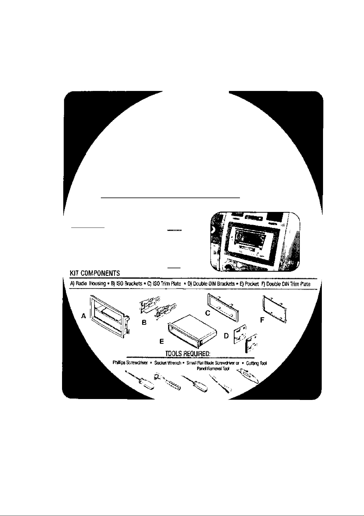
Km hbAiUHfcii
• OIN Radio Provision with Pochat
• ISO DiN Radio Provision with Pocket
• DouhJe DIN Radio Provision
• Stacked ISO Units Provision
Page 2

TABLE OF COIMTEIXITS
Dash Di sass em bly
• Chrysler Aspen 2007
• Dodg e D ura ngo 20 04- 200 6
■
Dodg e C har ger 20 05- 200 6
-
Dodg e M agn um 200 5-2 00 6
- Chrysle r 3 00 20 05-2 00 6
- D odg e R am 200 6 ( Wit hout Cent er Co nsol e}
-
Dodg e R am 200 6 ( Wit h M ini Ce nte r C ons ole )
-
Dodg e R am 200 6 ( Wit h F ull Ce nte r Cons ole )
• Jeep Gr and Ch ero kee 20 05- 200 6
-
Jeep Co mma nde r 2 006
Kit Ass embl y
-
DIM Rad io Pro vis ion wi th Poc ket
.................................
..........................................
...........................................
....................................
...............................................
...................................
...............................................
....................................
..................
...................
...
................
.1
1
2
...2
3
4
5
6
7
^
9
- I SO Rad io Pro vis ion wi th Poc ket
-
Doub ie DiH Ra dio Pr ovis io n
•
Stac ked IS O U nit s P rov isi on
Final A sse mbi v
..........................................................
..
....................
..
............................ ./2
....
..............................
10
13
Page 3
CHRYSLER ASPEIM gOD7
DODGE DURAIMGO B004-B00G
1
Disco nn ect th e n ega tiv e b att ery te rmi nal
to pr ev ent an ac cid ent al sho rt cir cuit .
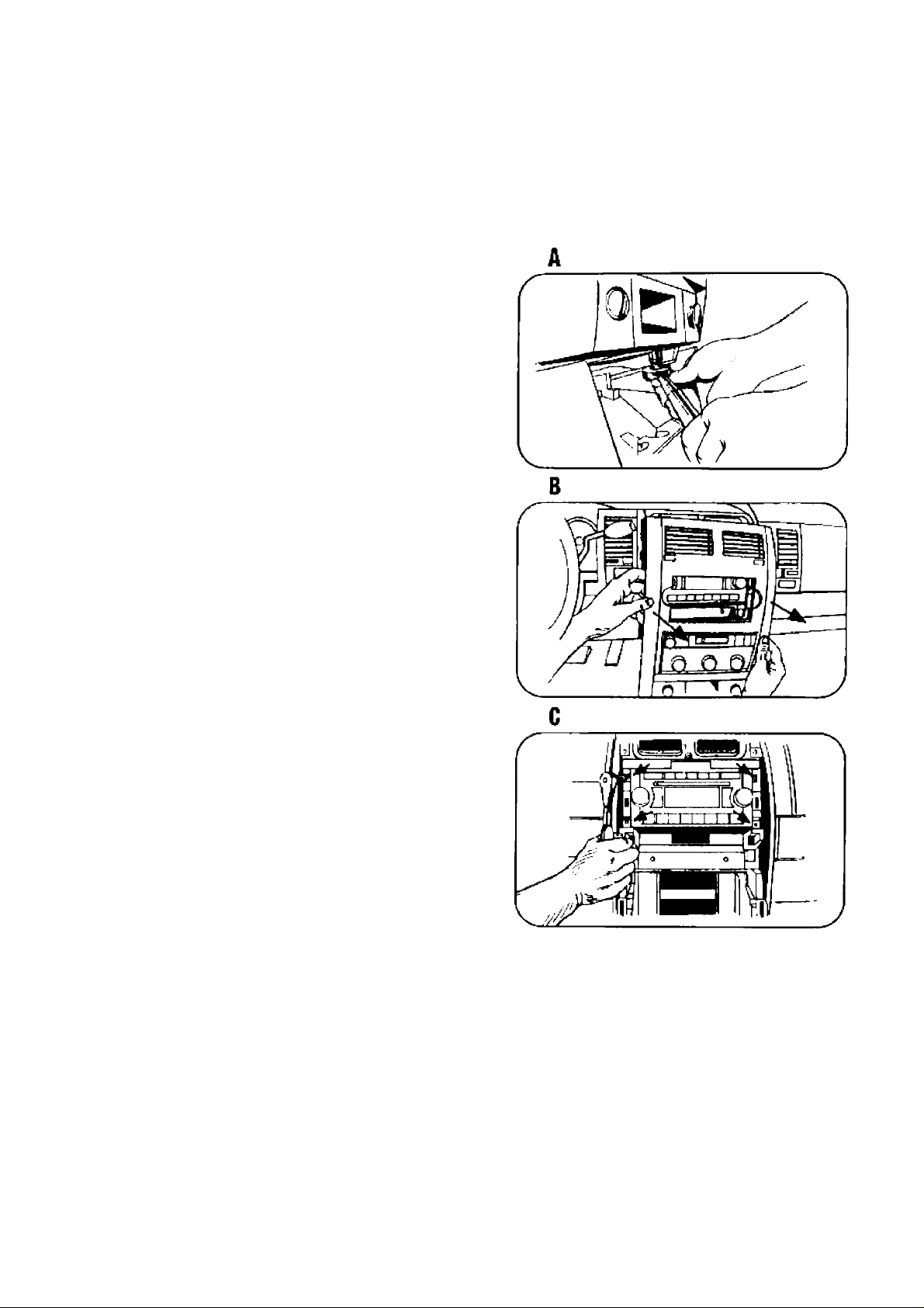
2
Remov e (2) 7M M s crew s fro m t he ins ide
of th e poc ket fac in g u pwa rd. (F igu re A)
3 Uncli p a nd re mov e t he ent ire tr im pan ei
surr oun din g t he r ad io a nd cl ima te con tro ls,
(Figu re 8)
4
Remov e (4) 7M M s crew s sec uri ng rad io
to da sh an d r emo ve r adi o. (F igu re C}
5 Conti nu e t o k it ass emb ly.
1
Page 4

DODGE CHARGER
DODGE fVIAGIMUIVI gQOS-gPDG
1
Disco nn ect th e n ega tiv e b att ery te rmi nal
to pr ev ent an ac cid ent al sho rt cir cuit ,
2
Uncli p a nd re mov e en ti re pan el sur rou ndi ng
radi o a nd cli mat e c ont rol s, Inc lud ing a/ c
vents . (Fig ure A )
3 Rem ove (4 ) 7MM sc rew s s ecu rin g r adio
to da sh an d r emo ve r adi o. (F igu re B)
4
Conti nu e t o k it ass emb ly.
g005-e006
Page 5

CHRYSLER 300 B005-e00B
1
Disco nn ect the negativ e battery termin al
to pr ev ent an ac cid ent al sho rt cir cuit .
2 Unclip and re mov e ent ire panel sur rou nd
ing radio and climat e contro ls, includ ing
a/c vent s a nd cl ock , ( Fig ure A)
3 Remov e (4) 7MM screw s secu rin g radio
to da sh an d r emo ve r adi o. (F igu re B)
4
Conti nu e t o k it ass emb ly.
Page 6

DODGE RAM 8006
WITHOUT CEIXITER COI^SOLE
1 Disco nn ect th e n ega tiv e b att ery te rmi nal
to pr ev ent an ac cid ent al sho rt cir cuit .
2 Open cu p h old er and re mov e ( 2) Phil li ps
screw s fac ing up on fr ont ed ge of
radi o/c lim ate con tr ol pan el. (F igu re A )
3 Uncli p a nd re mov e en ti re pan el sur
roun din g r adi o a nd clim at e c ont rols ,
incl udi ng a/c ve nts . ( Fig ure B)
4
Remov e (4) 7M M s crew s sec uri ng rad io
to da sh an d r emo ve r adi o.
5
Con ti nue to kit a sse mbly .
Page 7

DODGE RAM SOOB
WITH IVIIIMI CEIMTER CDIMSDLE
1 Disconnect the negative battery terminal
to prevent an accidental short circuit.
2 If vehicle has floor shifter, remove shifter
knob.
3 Remove center console inserts, if present,
(Figure A)
4 Remove screws securing the rear center
console to the floor panel. Lift up on the
rear center console to clear the gear shift
lever, if present. (Figure B)
5 Remove screws securing the front center
console to the floor panel. Unclip and
remove the front center console.
(Figure C)
6 Remove two phillips head screws at bottom
of dash, Unsnap and remove lower panel.
7 Remove (2) Phillips screws facing up on
front edge of radio/climate control panel.
(Figure D)
8 Unclip and remove entire panel sur
rounding radio and climate controls,
including a/c vents, (Figure E)
9 Remove (4) 7MM screws securing radio
to dash and remove radio.
10 (Continue to kit assembly.
Page 8

DODGE HAM BOOB
WITH FULL CE1\TER COiXiSDLE
Disconnect the negative battery terminal
to prevent an accidental short circuit.
If vehicle has floor shifter, remove shifter
knob,
I Unsnap and remove console front top
cover (closest to the dash}. (Figure A)
t Remove two 8 mm screws from under
consofe cover (previously removed).
Remove front section of console.
(Figure B)
5 Loosen two 8 mm screws at t>ottom of
dash. Unsnap lower panel.
6 Remove (2) Phillips screws facing up on
front edge of radio/climate control panel
(Figure D)
7 Unclip and remove entire panel surrounding
radio and climate controls, including a/c
vents. (Figure £)
8 Remove (4) 7MM screws securing radio
to dash and remove radio.
9 Continue to kit assembly.
Page 9

JEEP GRA1\1D CHEROKEE g005-gD0B
t Disconnect the negative battery terminal
to prevent an accidental short circuit.
2 Unsnap and remove panel from around
radio including the vent on each side.
(Figure A)
3 Remove (4) 7MM screws securing radio
to dash and remove radio. (Figure B)
4 Continue to kit assembly.
Page 10

JEEP COIVIIVIAMOER BOOB
Disconnect the negative battery terminal
to prevent an accidental short circuit.
! Remove the (16) screws securing the
radio trim panel, (Figure A)
3 Unclip and remove the entire radio trim
panel. (Figure B)
B
4 Remove (4) 7MM screws securing radio to dash and remove radio.
5 Continue to kit assembly.
8
Page 11

DIIM RADIO PROVISIOIM WITH POCKET
1 Slide the DIN cage into the radio
housing and secure by bending the
metal locking tabs down. (Figure A)
2 Slide the aftermarket radio into the
cage until secure. (Figure 8]
3 Snap the pocket into the radio
housing. (Figure C)
4 Continue to final assembly.
Page 12

ISO RADIO PROVISIOIM WITH POCKET
1 Mount the ISO Brackets to the radio
with the screws supplied with the
unit. (Figure A)
2
Slide the radio into the radio opening
until the side clips engage. (Figure B)
3 Snap the ISO Trim Plate into the
radio housing. (Figure C)
4 Snap the pocket into the radio housing.
(Figure C)
5 (kintinue to final assembly.
10
Page 13

DOUBLE Olivi RADIO PROVISIOIM
1 Cut and remove center divider in
radio housing. (Figure A)
2 Snap the DDIN brackets to the inside
edge of the radio housing. (Figure B)
Slide the DDIN radio unit into the
DDIN bracket/radio housing assem
bly and secure the radio unit to the
kit using the screws supplied with
the radio unit. (Figure C)
4 Snap the ODIN trim-plate onto the
housing/radio assembly. (Figure D)
5 Continue to final assembly.
11
Page 14

STACKED ISO UIXIITS PROVISIDIM
1 Cut and remove center divider in
radio housing. (Figure A}
2 Snap the ODIN brackets to the inside
edge of the radio housing. (Figure B)
3 Slide the stacked ISO DIN radio units
into the ODIN bracket/radio housing
assembly and secure the unit to the
kit using the screws supplied with
the units. (Figure C)
4 Snap the ODIN trim-piate onto the
housing/radio assembly. (Figure 0)
5 Continue to final assembly.
IB
 Loading...